JP3745461B2 - Pressurizing means fixing method and pressurizing means fixing tool - Google Patents
Pressurizing means fixing method and pressurizing means fixing tool Download PDFInfo
- Publication number
- JP3745461B2 JP3745461B2 JP19908796A JP19908796A JP3745461B2 JP 3745461 B2 JP3745461 B2 JP 3745461B2 JP 19908796 A JP19908796 A JP 19908796A JP 19908796 A JP19908796 A JP 19908796A JP 3745461 B2 JP3745461 B2 JP 3745461B2
- Authority
- JP
- Japan
- Prior art keywords
- gas cylinder
- sleeve body
- small gas
- pressurizing means
- inner diameter
- Prior art date
- Legal status (The legal status is an assumption and is not a legal conclusion. Google has not performed a legal analysis and makes no representation as to the accuracy of the status listed.)
- Expired - Fee Related
Links
- 238000000034 method Methods 0.000 title claims description 9
- 230000000149 penetrating effect Effects 0.000 claims description 7
- 238000009751 slip forming Methods 0.000 claims description 7
- 238000000605 extraction Methods 0.000 claims description 5
- 238000009834 vaporization Methods 0.000 claims description 4
- 230000008016 vaporization Effects 0.000 claims description 4
- 230000008014 freezing Effects 0.000 claims description 2
- 238000007710 freezing Methods 0.000 claims description 2
- XLYOFNOQVPJJNP-UHFFFAOYSA-N water Substances O XLYOFNOQVPJJNP-UHFFFAOYSA-N 0.000 claims 1
- CURLTUGMZLYLDI-UHFFFAOYSA-N Carbon dioxide Chemical compound O=C=O CURLTUGMZLYLDI-UHFFFAOYSA-N 0.000 description 14
- 235000013405 beer Nutrition 0.000 description 8
- 229910002092 carbon dioxide Inorganic materials 0.000 description 7
- 239000001569 carbon dioxide Substances 0.000 description 7
- 239000011347 resin Substances 0.000 description 5
- 229920005989 resin Polymers 0.000 description 5
- 238000000465 moulding Methods 0.000 description 3
- 239000007788 liquid Substances 0.000 description 2
- 238000004140 cleaning Methods 0.000 description 1
- 238000004891 communication Methods 0.000 description 1
- 238000010586 diagram Methods 0.000 description 1
- 230000000694 effects Effects 0.000 description 1
- 238000002347 injection Methods 0.000 description 1
- 239000007924 injection Substances 0.000 description 1
- 238000001746 injection moulding Methods 0.000 description 1
- 230000009191 jumping Effects 0.000 description 1
- 239000000463 material Substances 0.000 description 1
- 230000035515 penetration Effects 0.000 description 1
- 238000007789 sealing Methods 0.000 description 1
Images

Landscapes
- Devices For Dispensing Beverages (AREA)
- Closures For Containers (AREA)
- Filling Or Discharging Of Gas Storage Vessels (AREA)
Description
【0001】
【発明の属する技術分野】
本発明は、加圧手段の固定方法及び加圧手段の固定具に係り、特に加圧式ビア樽の専用栓に固定される注出器具に対して着脱自在に設けられる(炭酸ガス用)小型ガスボンベを交換のために取り外す際に、注出器具に凍結している小型ガスボンベが不用意に飛び出すことを防止して安全性を確保する技術に関するものである。
【0002】
【従来の技術】
加圧式ビア樽用の専用栓は、工場等においてビールを注入する機能と、店内等において注出器具を接続して加圧用の炭酸ガスを樽内に導入する機能と、小型ガスボンベから導入された炭酸ガスの加圧によりビールを樽の外部に注出する機能と、工場等においてビア樽の内面の洗浄を行うための少なくとも4つの機能が要求される。
【0003】
一方、加圧式ビア樽用の専用栓には注出器具が固定される。また、この注出器具には液化炭酸ガスが充填された小型ガスボンベが着脱可能に設けられ、気化した炭酸ガスを専用栓を介してビア樽内に導入することにより、樽内のビール液面を加圧して、注出器具側に設けられているレバーを操作することによりビールを注ぐようにしている。
【0004】
このように注出器具に対して小型ガスボンベを固定する様子を、添付の図面を参照して述べると、図4は従来の小型ガスボンベを固定する様子を破断して示した断面図(a)、要部破断図(b)である。
【0005】
本図において、小型ガスボンべ1は図示のような形状を有しており、胴部2から連続する肩部4と、この肩部4から連続形成される首部5と、この首部5の端部において樹脂からなる栓体7を設けた口金部6が形成されている。この栓体7は、特殊樹脂からなり、小型ガスボンベ1の口金部6に予め穿設されている開口部を液化ガスを充填した後に完全に封印するように構成されている。
【0006】
そして、この封印状態を保持した状態で提供されるものであり、注出器具30に対して小型ガスボンべ1を新たに固定した状態で、炭酸ガスをビア樽内(不図示)に供給可能にし、略空の状態になってから新品に交換されるようにして使用される。
【0007】
このように交換可能にするために、小型ガスボンベ1は固定具であるスリーブ体120の内径部124中に挿入してから、このスリーブ体120の内ネジ部122を加圧式ビア樽用の注出器具30側の外ネジ部10に対する螺合状態にするとともに、この螺合動作にともない小型ガスボンベ1の底部3をスリーブ体120の底部121で押圧して、図示の矢印方向に移動するようにして口金部6が完全に支持体9の表面に突き当たるまで移動して固定する。
【0008】
一方、注出器具30側の外ネジ部10の内部には支持体9を介して栓体7を穿通して、注出器具30内に液化ガスを供給可能にする先端部8bと連通路8aを設けた穿通体8が固定されており、図4(b)に示すように小型ガスボンベ内との間を連通するように構成されている。
【0009】
【発明が解決しようとする課題】
上記のようにスリーブ体120を使用して、小型ガスボンベ1を注出器具30に固定して、使用するものであるが、このとき液化ガスの気化熱で大気中の水分の温度が奪われることで凍結して、注出器具30の支持体9と口金部6の間が氷塊Kにより結合する状態になる。この氷塊Kは次第に成長することで、両者は完全に凍結して結合する場合もある。
【0010】
このように、注出器具30と小型ガスボンベの口金部6の間が氷塊Kにより結合する状態において、ガスボンベの交換のためにスリーブ体120の螺合を解除することによりそのまま取り外すと、凍結力により小型ガスボンベ1が注出器具30に固定された状態に留まり、やがて溶解して、ガスボンベ1の残圧の作用により突然ガスボンベが飛び出すことがある。このように突然飛び出すガスボンベは速度が大きい場合があるので、直に衝突すると危険である。
【0011】
従って、本発明は上述した問題点に鑑みてなされたものであり、その目的は、注出器具と小型ボンベの口金部の間が氷塊Kにより結合する状態であっても、小型ガスボンベの交換のために固定具の螺合を解除して取り出すときに、小型ガスボンべの凍結状態を分離するようにして突然飛び出すことを防止した安全性に優れる加圧手段の固定方法及び加圧手段の固定具の提供することにある。
【課題を解決するための手段】
上述した課題を解決し、目的を達成するために、本発明によれば、胴部から連続形成される肩部と、栓体を設けた口金部を有する小型ガスボンベ中に液化ガスを内蔵した加圧手段を、スリーブ体の内径部に挿入し、前記スリーブ体の内ネジ部を加圧式ビア樽用の注出器具側の外ネジ部に対する螺合状態にすることで、前記小型ガスボンベを長手方向に移動して、前記栓体を穿通し、前記注出器具に前記液化ガスを供給可能にする加圧手段の固定方法であって、前記肩部に対して当接することで前記小型ガスボンベの長手方向に略直交する分力を発生させるために、前記スリーブ体の前記内径部の内壁との間の距離Lが、前記小型ガスボンベの前記胴部の直径Dより大きく設定される上面を有する形状部を設けておき、前記スリーブ体の前記螺合状態の解除の初期段階における前記分力により、前記液化ガスの気化熱で大気中の水分が凍結して互いに凍結状態となっている前記注出器具と前記口金部を確実に分離することを特徴としている。
【0012】
また、好ましくは、胴部から連続形成される肩部と、栓体を設けた口金部を有する小型ガスボンベ中に液化ガスを内蔵した加圧手段を、固定具であるスリーブ体の内径部に挿入し、前記スリーブ体の内ネジ部を加圧式ビア樽用の注出器具側の外ネジ部に対する螺合状態にすることで、前記小型ガスボンベを長手方向に移動して、前記栓体を穿通し、前記注出器具に前記液化ガスを供給可能にする加圧手段の固定具であって、前記スリーブ体の前記螺合状態の解除の初期段階において、前記肩部に対して当接することで前記小型ガスボンベの長手方向に略直交する分力を発生させるために、前記スリーブ体の前記内径部の内壁面との間の距離Lが、前記小型ガスボンベの前記胴部の直径Dより大きく設定される上面を有する形状部を前記内径部に設けておき、前記分力により、前記液化ガスの気化熱で互いに凍結状態となっている前記注出器具と前記口金部を分離するように構成することを特徴としている。
【0013】
そして、好ましくは、前記スリーブ体の底部において貫通孔を設けるか、または前記スリーブ体の胴部において長手方向に開口する一対の開口孔部を設けることにより、前記内径部中の前記小型ガスボンベを前記スリーブ体の外部から容易に取り外せるように構成したことを特徴としている。
【0014】
【発明の実施の形態】
以下、図面を参照して実施形態を詳細に説明する。
【0015】
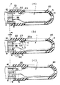
図1(a)は実施形態を示した小型ガスボンベを固定する様子を破断して示した断面図であり、(b)は(a)のA‐A矢視断面図、(c)は(a)のB‐B矢視断面図である。
【0016】
先ず、図1(a)において、図4で既に説明済みの構成には同一符号を付して説明を割愛して、未説明部分について述べると、小型ガスボンベ1は図示のような形状を有しており、胴部2の直径Dは約22mmであり、全長は約90mmである。この種の小型ガスボンベは近年になり自動車のパンク修理用としても多く提供されるようになっているので、比較的に入手が容易であるし、また液体炭酸ガスが内蔵されているので、人体に一切無害である。
【0017】
この小型ガスボンべ1の胴部2からは図示のように次第に直径を少なくするように連続形成された肩部4と、この肩部4から連続形成される首部5と樹脂からなる栓体を設けた口金部6が形成されている。
【0018】
また、この小型ガスボンベ1は固定具であるスリーブ体20の内径部24中に形状部23を介して図示のように挿入される。このために、図1(b)に示したように形状部23の上面23bと内径部24の間の距離Lは胴部2の直径Dより大きくなるように設定される。
【0019】
次に、このスリーブ体20の内ネジ部22を加圧式ビア樽(不図示)用の専用栓に固定された状態となっている注出器具30側の外ネジ部10に対する螺合状態にするとともに、この螺合動作にともない小型ガスボンベ1の底部3をスリーブ体20の底部21により押圧することで、図4で述べたように穿通体8を穿通する状態にする。
【0020】
スリーブ体20は、例えば所定樹脂材料から射出樹脂成形されるものであって、注出器具30側の外ネジ部10に螺合する内ネジ部22と、内径部24と形状部23とを少なくとも備えている。また、図1(c)に示すように、胴部2と内径部24の間には若干の隙間が設けられている。
【0021】
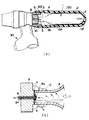
図1に示した状態において、ガスボンベが空になり、新品に交換するときの動作について、図2(a)から(c)の動作説明図で述べる。
【0022】
先ず、図2(a)において、スリーブ体20を矢印D1方向に回転することで、注出器具30側の外ネジ部10に螺合して固定することで、破線Pの位置でそれ以上の移動ができない状態となる。この位置において、注出器具30側の外ネジ部10の内部の支持体9の穿通体8を介して、注出器具30内に液化ガスを供給可能にし、連続使用により氷塊Kが成長する。この氷塊Kは次第に成長することで、両者は完全に凍結して結合する場合もある。
【0023】
このように、注出器具30と小型ガスボンベの口金部6の間が氷塊Kにより結合する状態において、図2(b)に示したように、小型ガスボンベ1の交換のためにスリーブ体20の螺合を解除するために矢印D2方向に回動して、破線Pの位置からP1の距離移動する、このときに形状部23の当接面23aがボンベ1の肩部4に当接することで、当接力Fを与えるようになる。
【0024】
この当接力Fは図示のように長手方向の分力F1と略垂直の分力F2となって肩部4に作用するが、このとき、ガスボンベ1に残圧があってもスリーブ体20は螺合している状態なので、ガスボンベがスリーブ体20の内径部の内部に留まるようにできるので、飛び出すことが防止される。
【0025】
また、分力F2の作用により、氷塊Kが完全に分断されることで凍結力により小型ガスボンベ1が注出器具30に固定された状態が完全に解消される。
【0026】
続いて、図2(c)に示すように、引く続きスリーブ体20を回転して完全に取り外す。この後に、ガスボンベをスリーブ体から取出して再度使用する。
【0027】
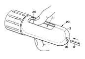
最後に、図3は、スリーブ体20の外観斜視図であり、氷塊Kが成長して、ガスボンベ1がスリーブ体20に固く留まる様子を示したものであり、このようにガスボンベ1がスリーブ体20内にあるときは、スリーブ体20の底部の貫通孔26に箸Wを入れるようにして出すようにするか、または長手方向に開口する一対の開口孔部25から指先を入れることにより、内径部24中の小型ガスボンベ1を容易に取り外せるように構成している。
【0028】
尚、上記の実施形態に限定されず、種々の構成が可能であることは勿論であって、例えばスリーブ体20を射出成形するための成形金型において、形状部23は所謂アンダー部となるので、成形金型においてスライド駒を設けた高額のものとなることから、この形状部23を別部品として個別に固定するようにしても良い。
【0029】
【発明の効果】
以上説明したように、本発明によれば、注出器具と小型ボンベの口金部の間が氷塊Kにより結合する状態でも、固定具であるスリーブ体の内径部に挿入される小型ガスボンベの交換のために固定具の螺合を解除して取り出すときに、小型ガスボンべの凍結状態を分離するようにして突然飛び出すことを防止した安全性に優れる加圧手段の固定方法及び加圧手段の固定具を提供することができる。
【0030】
【図面の簡単な説明】
【図1】(a)は実施形態を示した小型ガスボンベを固定する様子を破断して示した断面図であり、(b)は(a)のA‐A矢視断面図、(c)は(a)のB‐B矢視断面図である。
【図2】(a)から(c)は小型ガスボンベの着脱の際の動作説明図である。
【図3】スリーブ体20の外観斜視図である。
【図4】 (a)は従来の小型ガスボンベを固定する様子を破断して示した断面図、(b)は要部破断図(b)である。
【符号の説明】
1…小型ガスボンベ
2…胴部
3…底部
4…肩部
5…首部
6…口金部
7…栓体
8…穿通体
9…支持体
10…外ネジ部
20…スリーブ体
21…底部
22…内ネジ部
23…形状部
24…内径部
25…開口部
30…注出器具[0001]
BACKGROUND OF THE INVENTION
The present invention relates to a method for fixing a pressurizing means and a fixture for the pressurizing means, and in particular, a small gas cylinder (for carbon dioxide gas) that is detachably provided to a pouring tool fixed to a dedicated stopper of a pressurizing beer barrel. The present invention relates to a technique for ensuring safety by preventing a small gas cylinder frozen in a pouring tool from inadvertently popping out when removing for replacement.
[0002]
[Prior art]
Dedicated stoppers for pressurized beer barrels were introduced from small gas cylinders, functions for injecting beer in factories, etc., functions for connecting extraction devices in shops, etc., and introducing pressurized carbon dioxide into barrels. A function of pouring beer out of the barrel by pressurization of carbon dioxide and at least four functions for cleaning the inner surface of the beer barrel in a factory or the like are required.
[0003]
On the other hand, a pouring tool is fixed to a dedicated stopper for the pressurized beer barrel. In addition, a small gas cylinder filled with liquefied carbon dioxide gas is detachably provided in this pouring device, and the beer liquid level in the barrel is changed by introducing the vaporized carbon dioxide gas into the via barrel through a dedicated stopper. The beer is poured by operating the lever provided on the pouring device side under pressure.
[0004]
The manner in which the small gas cylinder is fixed to the dispensing device in this way will be described with reference to the accompanying drawings. FIG. 4 is a sectional view (a) showing a state in which the conventional small gas cylinder is fixed. It is a principal part broken view (b).
[0005]
In this figure, the
[0006]
And it is provided in the state which hold | maintained this sealing state, and enables carbon dioxide gas to be supplied in a via barrel (not shown) in the state where the
[0007]
In order to enable exchange in this way, the
[0008]
On the other hand, the
[0009]
[Problems to be solved by the invention]
The
[0010]
In this manner, in the state in which the
[0011]
Therefore, the present invention has been made in view of the above-described problems, and the object of the present invention is to replace a small gas cylinder even when the pouring tool and the base of the small cylinder are coupled by the ice block K. Therefore, when the screwing of the fixing tool is released and taken out, the fixing method of the pressurizing means and the fixing means of the pressurizing means excellent in safety, which prevents the small gas cylinder from being frozen out by separating it from being frozen. Is to provide.
[Means for Solving the Problems]
In order to solve the above-described problems and achieve the object, according to the present invention, a process is performed in which a liquefied gas is incorporated in a small gas cylinder having a shoulder portion continuously formed from the trunk portion and a base portion provided with a plug. A pressure means is inserted into the inner diameter portion of the sleeve body, and the inner screw portion of the sleeve body is screwed to the outer screw portion on the side of the dispensing device for the pressure-type via barrel, whereby the small gas cylinder is moved in the longitudinal direction. A pressurizing means fixing method that allows the liquefied gas to be supplied to the dispensing device by penetrating the plug body, and is in contact with the shoulder so that the length of the small gas cylinder In order to generate a component force substantially orthogonal to the direction, the shape portion having an upper surface in which the distance L between the inner diameter portion of the sleeve body and the inner wall of the small gas cylinder is set larger than the diameter D of the body portion. And providing a screw for the sleeve body. By the component force in the initial stage of the release of the state, the moisture in the atmosphere is frozen by the heat of vaporization of the liquefied gas, and the pouring device and the base part that are in a frozen state are reliably separated from each other. It is said.
[0012]
Preferably, a pressurizing means containing liquefied gas in a small gas cylinder having a shoulder part continuously formed from the body part and a base part provided with a plug is inserted into the inner diameter part of the sleeve body as a fixture. Then, the small gas cylinder is moved in the longitudinal direction by penetrating the plug body by bringing the inner thread portion of the sleeve body into a screwed state with respect to the outer thread portion on the side of the pouring device for the pressure-type via barrel. A fixing means for pressurizing means that enables supply of the liquefied gas to the dispensing device, wherein the sleeve body abuts against the shoulder portion in an initial stage of releasing the screwed state. In order to generate a component force substantially orthogonal to the longitudinal direction of the small gas cylinder, a distance L between the inner diameter portion of the sleeve body and the inner wall surface of the small gas cylinder is set to be larger than a diameter D of the body portion of the small gas cylinder. the inner diameter portion of the shaped portion having a top surface Provided advance, by the component force is characterized by configured to separate the cap portion and the spout instrument has a frozen state from each other in the heat of vaporization of the liquefied gas.
[0013]
Preferably, the small gas cylinder in the inner diameter portion is provided by providing a through hole in the bottom of the sleeve body or by providing a pair of opening holes that open in the longitudinal direction in the body of the sleeve body. It is characterized in that it can be easily removed from the outside of the sleeve body.
[0014]
DETAILED DESCRIPTION OF THE INVENTION
Hereinafter, embodiments will be described in detail with reference to the drawings.
[0015]
FIG. 1A is a cross-sectional view showing a state in which the small gas cylinder according to the embodiment is fixed. FIG. 1B is a cross-sectional view taken along the line AA in FIG. It is a BB arrow sectional view of).
[0016]
First, in FIG. 1 (a), the components already described in FIG. 4 are denoted by the same reference numerals and description thereof is omitted, and unexplained portions are described. The
[0017]
The body 2 of the
[0018]
The
[0019]
Next, the
[0020]
The
[0021]
The operation when the gas cylinder is empty and replaced with a new one in the state shown in FIG. 1 will be described with reference to the operation explanatory diagrams of FIGS.
[0022]
First, in FIG. 2 (a), the
[0023]
In this way, in a state where the pouring
[0024]
This contact force F acts on the
[0025]
Further, the state in which the
[0026]
Subsequently, as shown in FIG. 2 (c), the
[0027]
Finally, FIG. 3 is an external perspective view of the
[0028]
It should be noted that the present invention is not limited to the above embodiment, and various configurations are possible. Of course, in the molding die for injection molding the
[0029]
【The invention's effect】
As described above, according to the present invention, the small gas cylinder to be inserted into the inner diameter portion of the sleeve body, which is a fixture, can be replaced even when the pouring tool and the base portion of the small cylinder are coupled by the ice block K. Therefore, when the screwing of the fixing tool is released and taken out, the fixing method of the pressurizing means and the fixing means of the pressurizing means excellent in safety, which prevents the small gas cylinder from being frozen out by separating it from being frozen. Can be provided.
[0030]
[Brief description of the drawings]
FIG. 1A is a cross-sectional view showing a state in which a small gas cylinder according to an embodiment is fixed; FIG. 1B is a cross-sectional view taken along the line AA in FIG. It is BB arrow sectional drawing of (a).
FIGS. 2A to 2C are operation explanatory views when a small gas cylinder is attached and detached.
FIG. 3 is an external perspective view of a
4A is a cross-sectional view showing a state in which a conventional small gas cylinder is fixed, and FIG. 4B is a main part cut-away view (b).
[Explanation of symbols]
DESCRIPTION OF
Claims (3)
前記肩部に対して当接することで前記小型ガスボンベの長手方向に略直交する分力を発生させるために、前記スリーブ体の前記内径部の内壁面との間の距離Lが、前記小型ガスボンベの前記胴部の直径Dより大きく設定される上面を有する形状部を設けておき、前記スリーブ体の前記螺合状態の解除の初期段階における前記分力により、前記液化ガスの気化熱で大気中の水分が凍結して互いに凍結状態となっている前記注出器具と前記口金部を確実に分離することを特徴とする加圧手段の固定方法。A pressurizing means containing a liquefied gas in a small gas cylinder having a shoulder part continuously formed from the body part and a base part provided with a plug is inserted into the inner diameter part of the sleeve body, and the inner thread part of the sleeve body In a screwed state with respect to the external thread portion on the side of the dispensing tool for the pressurized via barrel, the small gas cylinder is moved in the longitudinal direction, the plug body is pierced, and the liquefied gas is passed through the dispensing tool. A method of fixing the pressurizing means that makes it possible to supply
In order to generate a component force substantially perpendicular to the longitudinal direction of the small gas cylinder by abutting against the shoulder portion, a distance L between the inner wall surface of the inner diameter portion of the sleeve body is set to A shape portion having an upper surface set larger than the diameter D of the body portion is provided, and the component force in the initial stage of releasing the screwed state of the sleeve body causes the heat of vaporization of the liquefied gas to occur in the atmosphere. A method of fixing a pressurizing means, wherein the pouring device and the base part, which are in a frozen state due to freezing of water, are reliably separated.
前記スリーブ体の前記螺合状態の解除の初期段階において、前記肩部に対して当接することで前記小型ガスボンベの長手方向に略直交する分力を発生させるために、前記スリーブ体の前記内径部の内壁面との間の距離Lが、前記小型ガスボンベの前記胴部の直径Dより大きく設定される上面を有する形状部を前記内径部に設けておき、前記分力により、前記液化ガスの気化熱で互いに凍結状態となっている前記注出器具と前記口金部を分離するように構成することを特徴とする加圧手段の固定具。A pressurizing means containing a liquefied gas in a small gas cylinder having a shoulder part continuously formed from the body part and a base part provided with a plug is inserted into the inner diameter part of the sleeve body which is a fixture, and the sleeve body The internal screw portion of the pressure-type via barrel is screwed to the external screw portion on the side of the extraction tool for the pressure-type via barrel, thereby moving the small gas cylinder in the longitudinal direction and penetrating the plug body. A pressurizing means fixing device capable of supplying the liquefied gas,
In the initial stage of releasing the screwed state of the sleeve body, the inner diameter portion of the sleeve body is generated to generate a component force substantially perpendicular to the longitudinal direction of the small gas cylinder by contacting the shoulder portion. A shape portion having an upper surface in which a distance L between the inner wall surface of the small gas cylinder is set larger than a diameter D of the body portion of the small gas cylinder is provided in the inner diameter portion, and the liquefied gas is vaporized by the component force. A fixing tool for pressurizing means, wherein the pouring tool and the base part, which are in a frozen state due to heat, are separated from each other.
Priority Applications (1)
| Application Number | Priority Date | Filing Date | Title |
|---|---|---|---|
| JP19908796A JP3745461B2 (en) | 1996-07-29 | 1996-07-29 | Pressurizing means fixing method and pressurizing means fixing tool |
Applications Claiming Priority (1)
| Application Number | Priority Date | Filing Date | Title |
|---|---|---|---|
| JP19908796A JP3745461B2 (en) | 1996-07-29 | 1996-07-29 | Pressurizing means fixing method and pressurizing means fixing tool |
Publications (2)
| Publication Number | Publication Date |
|---|---|
| JPH1035790A JPH1035790A (en) | 1998-02-10 |
| JP3745461B2 true JP3745461B2 (en) | 2006-02-15 |
Family
ID=16401895
Family Applications (1)
| Application Number | Title | Priority Date | Filing Date |
|---|---|---|---|
| JP19908796A Expired - Fee Related JP3745461B2 (en) | 1996-07-29 | 1996-07-29 | Pressurizing means fixing method and pressurizing means fixing tool |
Country Status (1)
| Country | Link |
|---|---|
| JP (1) | JP3745461B2 (en) |
Families Citing this family (1)
| Publication number | Priority date | Publication date | Assignee | Title |
|---|---|---|---|---|
| US6432102B2 (en) | 1999-03-15 | 2002-08-13 | Cryovascular Systems, Inc. | Cryosurgical fluid supply |
-
1996
- 1996-07-29 JP JP19908796A patent/JP3745461B2/en not_active Expired - Fee Related
Also Published As
| Publication number | Publication date |
|---|---|
| JPH1035790A (en) | 1998-02-10 |
Similar Documents
| Publication | Publication Date | Title |
|---|---|---|
| CN108025268B (en) | Coupling of gas cartridges to gas distributors | |
| HUP9900222A2 (en) | Cryogen fluid cylinder filling system | |
| FR2804666B1 (en) | DISPENSER FOR STORING AT LEAST TWO COMPONENTS AND SELECTIVE DISPENSING EITHER OF A SINGLE CONSTITUENT, EITHER OF THEIR MIXTURE, AND METHOD FOR THE IMPLEMENTATION THEREOF | |
| CA2173823A1 (en) | Apparatus for combining a first liquid component and a second solid or liquid component by means of reduced pressure under sterile conditions | |
| KR900002132B1 (en) | Liquid filling device | |
| JP3745461B2 (en) | Pressurizing means fixing method and pressurizing means fixing tool | |
| NO822924L (en) | PROCEDURE FOR THE PREPARATION OF A PLASTIC TUBE WITH THE ACCESSORIES CLOSED CAPS, AND THE IMPLEMENTATION PROCEDURE | |
| US20180106431A1 (en) | Cylinder exclusive connection | |
| US2921711A (en) | Pressure applicator | |
| US5884789A (en) | Cork removal apparatus | |
| GB9607794D0 (en) | Valve apparatus | |
| US10000320B2 (en) | Wine cork with built-in gas activated mini-corkscrew | |
| JP2773856B2 (en) | Air cylinder connection device for air brush | |
| WO2002101221A3 (en) | A method and apparatus for the preparation and usage of a cryogenic propellant or explosive system | |
| US2839221A (en) | Device for tapping under pressure a gas containing liquid from a bottle or a can, for instance beer | |
| PL361046A1 (en) | Safety valve for tank containing a pressurised liquid fluid such as lpg | |
| US20110265909A1 (en) | Device for filling air tires with a tire sealing fluid | |
| JPH05180439A (en) | Method for filling gas for disposable gas lighter and disposable gas lighter | |
| JP4964510B2 (en) | Residual gas discharge structure of aerosol container | |
| KR200313958Y1 (en) | An ink bottle | |
| KR19980031678U (en) | Gas bottle cap with residual gas discharge function of waste gas bottle | |
| JP2002264994A (en) | Beer server | |
| JP3983683B2 (en) | Simple air blow device | |
| JPH07112775A (en) | Aerosol spray container with heavy bob for fixing to flexible pipe and heavy bob to flexible liquid supply pipe, aerosol spray container capable of filling at high speed under pressure and method for filling at high speed under pressure by this container | |
| EP0822369B1 (en) | Distribution system for gas |
Legal Events
| Date | Code | Title | Description |
|---|---|---|---|
| A977 | Report on retrieval |
Free format text: JAPANESE INTERMEDIATE CODE: A971007 Effective date: 20050610 |
|
| A131 | Notification of reasons for refusal |
Free format text: JAPANESE INTERMEDIATE CODE: A131 Effective date: 20050614 |
|
| RD04 | Notification of resignation of power of attorney |
Free format text: JAPANESE INTERMEDIATE CODE: A7424 Effective date: 20050714 |
|
| A521 | Written amendment |
Free format text: JAPANESE INTERMEDIATE CODE: A523 Effective date: 20050815 |
|
| TRDD | Decision of grant or rejection written | ||
| A01 | Written decision to grant a patent or to grant a registration (utility model) |
Free format text: JAPANESE INTERMEDIATE CODE: A01 Effective date: 20051021 |
|
| A61 | First payment of annual fees (during grant procedure) |
Free format text: JAPANESE INTERMEDIATE CODE: A61 Effective date: 20051117 |
|
| R150 | Certificate of patent or registration of utility model |
Free format text: JAPANESE INTERMEDIATE CODE: R150 |
|
| FPAY | Renewal fee payment (event date is renewal date of database) |
Free format text: PAYMENT UNTIL: 20111202 Year of fee payment: 6 |
|
| LAPS | Cancellation because of no payment of annual fees |