JP3736282B2 - Vibration type linear actuator - Google Patents
Vibration type linear actuator Download PDFInfo
- Publication number
- JP3736282B2 JP3736282B2 JP2000124541A JP2000124541A JP3736282B2 JP 3736282 B2 JP3736282 B2 JP 3736282B2 JP 2000124541 A JP2000124541 A JP 2000124541A JP 2000124541 A JP2000124541 A JP 2000124541A JP 3736282 B2 JP3736282 B2 JP 3736282B2
- Authority
- JP
- Japan
- Prior art keywords
- mover
- movers
- permanent magnet
- linear actuator
- type linear
- Prior art date
- Legal status (The legal status is an assumption and is not a legal conclusion. Google has not performed a legal analysis and makes no representation as to the accuracy of the status listed.)
- Expired - Fee Related
Links
- 230000008878 coupling Effects 0.000 claims description 2
- 238000010168 coupling process Methods 0.000 claims description 2
- 238000005859 coupling reaction Methods 0.000 claims description 2
- 230000005484 gravity Effects 0.000 description 6
- 230000004907 flux Effects 0.000 description 5
- 230000001141 propulsive effect Effects 0.000 description 4
- 239000000696 magnetic material Substances 0.000 description 3
- XEEYBQQBJWHFJM-UHFFFAOYSA-N Iron Chemical compound [Fe] XEEYBQQBJWHFJM-UHFFFAOYSA-N 0.000 description 2
- 238000010586 diagram Methods 0.000 description 2
- 239000000463 material Substances 0.000 description 2
- 238000003466 welding Methods 0.000 description 2
- 230000002411 adverse Effects 0.000 description 1
- 238000005452 bending Methods 0.000 description 1
- 230000006835 compression Effects 0.000 description 1
- 238000007906 compression Methods 0.000 description 1
- 230000000694 effects Effects 0.000 description 1
- 229910052742 iron Inorganic materials 0.000 description 1
- 229920003002 synthetic resin Polymers 0.000 description 1
- 239000000057 synthetic resin Substances 0.000 description 1
Images


Landscapes
- Dry Shavers And Clippers (AREA)
- Reciprocating, Oscillating Or Vibrating Motors (AREA)
Description
【0001】
【発明の属する技術分野】
本発明は往復振動を得るための振動型リニアアクチュエータに関するものである。
【0002】
【従来の技術】
従来、この種の振動型リニアアクチュエータとしては特開平11−285226号公報等に開示されるものがある。これは、電磁石からなる固定子と、永久磁石を備えている複数の可動子と、固定子が固着されていると共に板ばね状の連結体を介して可動子を往復動自在に支持しているフレームからなり、複数の可動子が駆動の振動方向にばねにて連結されている。そして電磁石に供給する電流の向きを交互に変えることより夫々永久磁石を備えた可動子を互いに逆位相で駆動させるようになっている。
【0003】
【発明が解決しようとする課題】
ところで、上記従来例では複数の可動子に夫々永久磁石を配設してあるが、このようにしてあると、複数の可動子の夫々の永久磁石同士に吸引力が発生し、その吸引力が磁気回路を構成する上で損失になり、磁気回路の効率に悪影響を与えているという問題があった。また隣り合う可動子に永久磁石を配設する際には、隣り合う永久磁石間に一定以上の隙間を設ける必要があるため、隙間の分だけアクチュエータの寸法が大きくなるという問題がある。
【0004】
本発明は叙述の点に鑑みてなされたものであって、従来の永久磁石間に働く吸引力成分をなくして磁気回路の効率を向上できる振動型リニアアクチュエータを提供することを課題とする。
【0005】
【課題を解決するための手段】
上記課題を解決するため本発明の請求項1の振動型リニアアクチュエータは、電磁石からなる固定子と、永久磁石を備えている可動子と、固定子が固着されていると共に板ばね状の連結体を介して可動子を往復動自在に支持しているフレームからなり、複数の可動子が駆動の振動方向にばねにて連結され、複数の可動子の質量は略同一で隣り合う可動子の片方のみに永久磁石が設けられ、唯一の電磁石に供給する電流の向きを交互に変えることで振動系の固有振動数付近で可動子を互いに逆位相で駆動させるようにしたことを特徴とする。片方の可動子に永久磁石を設ける構造で複数の可動子を逆位相で駆動することができる。このため従来のように隣り合う可動子に永久磁石がないために隣り合う永久磁石同士の吸引力が発生しないため、磁気回路に用いる磁束の損失がなくなり、磁気回路の効率が向上する。
【0006】
また本発明の請求項2の振動型リニアアクチュエータは、請求項1において、電磁石と対向している永久磁石の面積はすべての可動子が永久磁石を有している時の面積と同等であることを特徴とする。電磁石と対向する永久磁石の総面積が従来と同等でも従来のように永久磁石同士の吸引力が生じないため、出力が従来と同等以上で、従来のように隣り合う永久磁石間に隙間を設けなくてもよい分だけアクチュエータを薄型化できる。
【0007】
また本発明の請求項3の振動型リニアアクチュエータは、請求項1において、唯一の可動子のみが複数の駆動子を有したことを特徴とする。駆動子を持たない可動子の形状自由度及び材質の自由度が大きくなり、出力は同等でもアクチュエータの設計自由度が大きくなる。
【0008】
また本発明の請求項4の振動型リニアアクチュエータは、請求項1において、磁気回路を構成する永久磁石を有する可動子には駆動子を配設しないことを特徴とする。各々の可動子が駆動子と永久磁石を別々に有しているために、可動子間の質量バランス設計が容易になる。
【0009】
また本発明の請求項5の振動型リニアアクチュエータは、請求項1において、可動体を2個連結して箱状にした可動子と、その可動子内に配設される中央の可動子からなり、どちらか一方の可動子のみが奥行き方向の中心を中心として対称に配置された2つの駆動子を有したことを特徴とする。各々の可動子が駆動方向と垂直方向で中心軸に対して対称形状をしているため、駆動方向と垂直方向の各可動子の重心位置が略一致し、アクチュエータの振動が低減できる。
【0010】
また本発明の請求項6の振動型リニアアクチュエータは、請求項4において、可動体を2個連結して箱状にした可動子と、その可動子内に配設される中央の可動子からなり、箱状の可動子のみが磁気回路を構成している永久磁石を有し、中央の可動子のみが駆動子を有したことを特徴とする。各々の可動子が駆動子と永久磁石を別々に有しているため、可動子間の質量バランス設計が容易になると共に、各々の可動子が駆動方向と垂直方向で中心軸に対して対称形状をしているため、駆動方向と垂直方向の各可動子の重心位置が略一致し、アクチュエータの振動が低減できる。
【0011】
また本発明の請求項7の振動型リニアアクチュエータは、請求項4において、
可動体を2個連結して箱状にした可動子と、その可動子内に配設される中央の可動子からなり、中央の可動子のみが磁気回路を構成している永久磁石を有し、箱状の可動子のみが駆動子を有したことを特徴とする。各々の可動子が駆動子と永久磁石を別々に有しているため、可動子間の質量バランス設計が容易になると共に、各々の可動子が駆動方向と垂直方向で中心軸に対して対称形状をしているため、駆動方向と垂直方向の各可動子の重心位置が略一致し、アクチュエータの振動が低減できる。
【0012】
【発明の実施の形態】
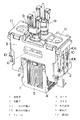
以下、本発明を添付図面に示す例に基づいて詳述する。図示例の振動型リニアアクチュエータは、往復式電気かみそり用のもので、固定子1と可動子2(図示例では2つの可動子2a,2b)、そしてフレーム3から構成されている。固定子1は、磁性材料の燒結体や磁性材料の鉄板を積層したE字形のヨーク4と、このヨーク4の中央片に巻回されたコイル5からなる電磁石となっており、断面略U字状のフレーム3に溶接またはねじにより固定されている。
【0013】
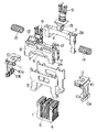
2種類の可動子2a,2bはいずれも合成樹脂よりなる骨組部材6にて主体が構成されており、一方の可動子2aの骨組部材6には磁性材料のバックヨーク7を介して永久磁石8が設けられている(他方の可動子2bにはバックヨーク7や永久磁石8は設けられていない)。勿論、可動子2bにバックヨーク7や永久磁石8を設け、可動子2aにこれらを設けなくてもよい。一方の可動子2aの骨組部材6は平面形状が略ロ字形の箱状に形成されており、他方の可動子2bが一方の可動子2aの両側片間に配設されている。可動子2a,2bには電気かみそりの可動刃に連結するための駆動子9が上方に突設されている。
【0014】
そして上記両可動子2a,2bは、その両端が前記フレーム3に板ばね状の連結体10を介して連結されている。ここにおける連結体10は可動子2bに連結される中央の板ばね部10bと、可動子2aに下端が連結される左右一対の板ばね部10aとからなり、連結体10の上端が支持板11を介してフレーム3に溶接、ねじ等で固定されている。つまり、上記可動子2a,2bが板ばね状の連結体10にてフレーム3から吊り下げられた形態となっている。上記支持板11は振動型リニアアクチュエータと他部品とを固定する基台となっている。また可動子2aの内面のばね受け部12と可動子2bの駆動子9のばね受け部13との間には、可動子2a,2bの往復動方向において、圧縮コイルばねからなるばね14が配設されている。
【0015】
このように構成された振動型リニアアクチュエータにおいて可動子2aに設けられた永久磁石8は、前記固定子1にギャップを介して上下方向に対向するとともに、可動子2aの往復動方向に着磁されていることから、固定子1のコイル5に流す電流の方向に応じて連結体10を撓ませつつ左右に移動する。コイル5に流す電流の方向を適宜なタイミングで切り換えることよって可動子2aを往復運動させることができる。
【0016】
上記可動子2a,2bの質量は、振動型リニアアクチュエータの振動系の共振の固有振動数で駆動するように設定され、夫々の質量は略同一になっている。そのため、夫々の可動子2a,2bはばね14を介して互いに往復運動の左右逆方向に運動を行う。つまり、逆位相で運動を行う。
【0017】
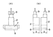
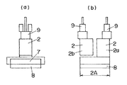
図3(a)(b)には従来例の可動子2の概略正面図及び概略側面図を示し、図4(a)(b)には本発明の可動子2の概略正面図及び概略側面図を示してある。本発明では可動子2a,2bはばね14により振動方向に連結されており、電磁石よりなる固定子1と面対向して永久磁石8の面積が従来の全ての可動子2が永久磁石8を有しているときの面積と同等である。つまり、従来の固定子1と面対向している2つの永久磁石8の総面積と、本発明の固定子1と面対向している1つの永久磁石8の面積とは同等である(A+A=2A)。本発明の振動型リニアアクチュエータは永久磁石8の面積に比例して推進力が得られる。この推進力Fの理論式を示すと次の数式1の通りとなる。
【0018】
【数1】
数式1でBr:磁束密度、aL:磁石厚、Z:厚み方向の磁石幅、E:総ギャップ、n:コイル巻数、I:電流である。
このように推進力Fは磁石の面積に比例する。このため本発明のものも従来例のものも略同等の推進力が得られるが、本発明のものは従来のように隣り合う永久磁石8間で磁束の流れがなくなり、磁束により発生する推力が推進力成分にのみ作用するため、磁気回路の効率が向上する。さらに、本発明の場合、従来のように隣り合う可動子2同士の永久磁石8の吸引力を考慮した隙間をあける必要がない。その結果、従来と同等の出力を得るのに隙間分だけ寸法の小さい振動型リニアアクチュエータが設計できる。
【0020】
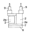
図5は他の例を示す。上記例の場合、2つの可動子2a,2bに夫々駆動子9を配設してあるが、本例の場合、1つの可動子2aのみに駆動子9を配設してある。この例の場合、駆動子9を持たない可動子2bが存在し、可動子2bの設計の形状自由度が向上する。
【0021】
図6は他の例を示す。本例の場合、永久磁石8とバックヨーク7を持たない可動子2bにのみに駆動子9が配設されている。可動子2の質量は永久磁石8、バックヨーク7及び駆動子9が大半を占めている。本例では永久磁石8及びバックヨーク7とを持ち、駆動子9を持たない可動子2aと、駆動子9を持ち、永久磁石8及びバックヨーク7を持たない可動子2bに分かれるため、片方の可動子2のみの質量が極端に大きくなりにくい。その結果、相互の可動子2a,2b間の質量設計が容易になると共に、質量を略同一にするために可動子2を重くするよな設計の必要がなくなる。
【0022】
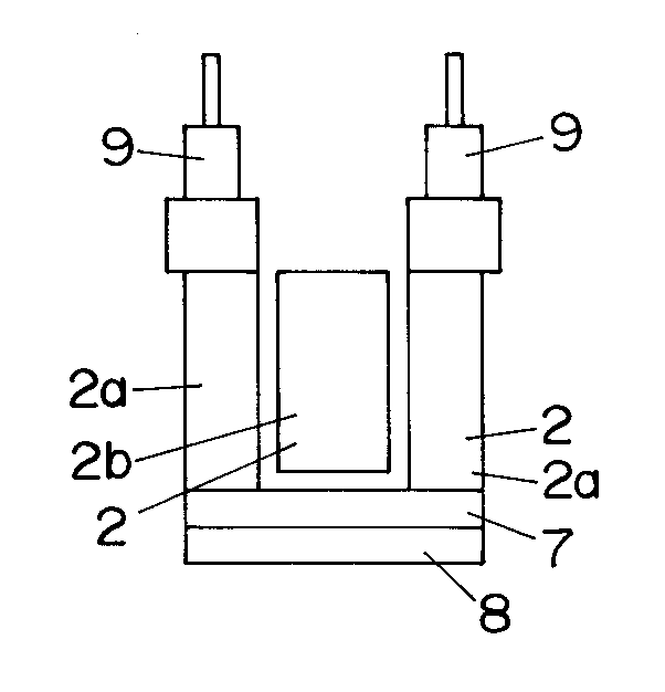
図7は他の例を示す。可動子2が、2個の可動体を2個連結して箱状にした可動子2aと、その箱状の可動子2aの中に配置される中央の可動子2bとからなっている。上記可動子2a,2bのどちらか一方のみが奥行き方向(駆動方向と直交する方向)の中心を中心として対称に配設された駆動子9を有している。図の例の場合、可動子2aの方に対称に駆動子9を有している。その結果、可動子2a,2bの振動方向と垂直方向の重心位置が可動子2a,2bの略中心となる。つまり、各々の可動子2a,2bの重心が可動子2a,2bの振動の作用線上にあり、振動型リニアアクチュエータの振動の低減が図れる。
【0023】
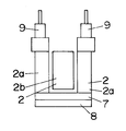
図8は他の例を示す。図8(a)は中央の可動子2bのみが奥行き方向の中心を中心として対称に配設された2つの駆動子9を有し、可動体を2個連結して箱状にした可動子2aが永久磁石8及びバックヨーク7を有している。図8(b)は可動体を2個連結して箱状にした可動子2aのみが奥行き方向の中心を中心として対称に配置された2つの駆動子9を有し、中央の可動子2bが永久磁石8及びバックヨーク7を有している。上記のように構成することにより、図8に示すものでは、相互の可動子2a,2b間の質量設計が容易になると共に質量を略同一にするために可動子2を重くするような設計が必要なくなる。
【0024】
【発明の効果】
本発明の請求項1の発明は、電磁石からなる固定子と、永久磁石を備えている可動子と、固定子が固着されていると共に板ばね状の連結体を介して可動子を往復動自在に支持しているフレームからなり、複数の可動子が駆動の振動方向にばねにて連結され、複数の可動子の質量は略同一で隣り合う可動子の片方のみに永久磁石が設けられ、唯一の電磁石に供給する電流の向きを交互に変えることで振動系の固有振動数付近で可動子を互いに逆位相で駆動させるようにしたので、片方の可動子に永久磁石を設ける構造で複数の可動子を逆位相で駆動することができるものであって、従来のように隣り合う可動子に永久磁石がないために隣り合う永久磁石同士の吸引力が発生しなく、磁気回路に用いる磁束の損失がなくなり、磁気回路の効率が向上するものである。
【0025】
また本発明の請求項2の発明は、請求項1において、電磁石と対向している永久磁石の面積はすべての可動子が永久磁石を有している時の面積と同等であるので、電磁石と対向する永久磁石の総面積が従来と同等でも従来のように永久磁石同士の吸引力が生じなく、出力が従来と同等以上で、従来のように隣り合う永久磁石間に隙間を設けなくてもよい分だけアクチュエータを薄型化できるものである。
【0026】
また本発明の請求項3の発明は、請求項1において、唯一の可動子のみが複数の駆動子を有したので、駆動子を持たない可動子の形状自由度及び材質の自由度が大きくなり、出力は同等でもアクチュエータの設計自由度が大きくなるものである。
【0027】
また本発明の請求項4の発明は、請求項1において、磁気回路を構成する永久磁石を有する可動子には駆動子を配設しないので、各々の可動子が駆動子と永久磁石を別々に有していることとなり、可動子間の質量バランス設計が容易になるものである。
【0028】
また本発明の請求項5の発明は、請求項1において、可動体を2個連結して箱状にした可動子と、その可動子内に配設される中央の可動子からなり、どちらか一方の可動子のみが奥行き方向の中心を中心として対称に配置された2つの駆動子を有したので、各々の可動子が駆動方向と垂直方向で中心軸に対して対称形状となり、駆動方向と垂直方向の各可動子の重心位置が略一致し、アクチュエータぼ振動が低減できるものである。
【0029】
また本発明の請求項6の発明は、請求項4において、可動体を2個連結して箱状にした可動子と、その可動子内に配設される中央の可動子からなり、箱状の可動子のみが磁気回路を構成して永久磁石を有し、中央の可動子のみが駆動子を有したので、各々の可動子が駆動子と永久磁石を別々に有していることとなり、可動子間の質量バランス設計が容易になると共に、各々の可動子が駆動方向と垂直方向で中心軸に対して対称形状をしているため、駆動方向と垂直方向の各可動子の重心位置が略一致し、アクチュエータの振動が低減できるものである。
【0030】
また本発明の請求項7の発明は、請求項4において、可動体を2個連結して箱状にした可動子と、その可動子内に配設される中央の可動子からなり、中央の可動子のみが磁気回路を構成している永久磁石を有し、箱状の可動子のみが駆動子を有したので、各々の可動子が駆動子と永久磁石を別々に有していることとなり、可動子間の質量バランス設計が容易になると共に、各々の可動子が駆動方向と垂直方向で中心軸に対して対称形状をしているため、駆動方向と垂直方向の各可動子の重心位置が略一致し、アクチュエータの振動が低減できるものである。
【図面の簡単な説明】
【図1】本発明の実施の形態の一例の振動型アクチュエータを示す斜視図である。
【図2】同上の分解斜視図である。
【図3】同上の動作を説明するためのもので、(a)は従来の可動子の概略正面図、(b)は従来の可動子の概略側面図である。
【図4】同上の動作を説明するためのもので、(a)は本発明の可動子の概略正面図、(b)は概略側面図である。
【図5】同上の他の例の可動子の概略側面図である。
【図6】同上の他の例の可動子の概略側面図である。
【図7】同上の他の例の可動子の概略側面図である。
【図8】(a)(b)は同上の他の例の概略側面図である。
【符号の説明】
1 固定子
2 可動子
2a 一方の可動子
2b 他方の可動子
3 フレーム
4 ヨーク
5 コイル
7 バックヨーク
8 永久磁石
9 駆動子
10 連結体
14 ばね[0001]
BACKGROUND OF THE INVENTION
The present invention relates to a vibration type linear actuator for obtaining reciprocating vibration.
[0002]
[Prior art]
Conventionally, as this type of vibration type linear actuator, there is one disclosed in JP-A-11-285226. This includes a stator made of an electromagnet, a plurality of movers provided with permanent magnets, a stator fixed thereto, and a reciprocating support for the mover supported via a leaf spring-like connecting body. It consists of a frame, and a plurality of movers are connected by a spring in the driving vibration direction. By alternately changing the direction of the current supplied to the electromagnet, the movers each having a permanent magnet are driven in opposite phases.
[0003]
[Problems to be solved by the invention]
By the way, in the above conventional example, the permanent magnets are arranged on the plurality of movable elements, respectively. However, if this is done, an attractive force is generated between the permanent magnets of the plurality of movable elements. There is a problem that a loss occurs in configuring the magnetic circuit, which adversely affects the efficiency of the magnetic circuit. Further, when the permanent magnets are disposed on the adjacent movable elements, it is necessary to provide a certain gap or more between the adjacent permanent magnets, and there is a problem that the size of the actuator is increased by the gap.
[0004]
The present invention has been made in view of the description, and it is an object of the present invention to provide a vibration type linear actuator capable of improving the efficiency of a magnetic circuit by eliminating an attractive force component acting between conventional permanent magnets.
[0005]
[Means for Solving the Problems]
In order to solve the above-mentioned problems, a vibration type linear actuator according to a first aspect of the present invention includes a stator composed of an electromagnet, a mover provided with a permanent magnet, a stator and a leaf spring-like coupling body. A plurality of movers connected by springs in the vibration direction of the drive, and the masses of the plurality of movers are substantially the same and one of the adjacent movers Only the permanent magnet is provided, and the direction of the current supplied to the only electromagnet is alternately changed to drive the mover in the opposite phase in the vicinity of the natural frequency of the vibration system. A plurality of movers can be driven in opposite phases with a structure in which a permanent magnet is provided on one of the movers. For this reason, since there is no permanent magnet in the adjacent mover as in the prior art, the attractive force between the adjacent permanent magnets is not generated, so that the loss of magnetic flux used in the magnetic circuit is eliminated and the efficiency of the magnetic circuit is improved.
[0006]
Further, in the vibration type linear actuator according to
[0007]
The vibration type linear actuator according to
[0008]
According to a fourth aspect of the present invention, there is provided the vibration type linear actuator according to the first aspect, wherein no drive element is provided on the movable element having a permanent magnet constituting the magnetic circuit. Since each mover has a driver and a permanent magnet separately, the mass balance design between the movers becomes easy.
[0009]
According to a fifth aspect of the present invention, there is provided a vibration type linear actuator according to the first aspect, comprising: a movable element formed by connecting two movable bodies into a box shape; and a central movable element disposed in the movable element. Only one of the movable elements has two drive elements arranged symmetrically about the center in the depth direction. Since each movable element has a symmetrical shape with respect to the central axis in the direction perpendicular to the driving direction, the center of gravity of each movable element in the driving direction and the vertical direction substantially coincide with each other, and the vibration of the actuator can be reduced.
[0010]
According to a sixth aspect of the present invention, there is provided a vibration type linear actuator according to the fourth aspect, comprising: a movable element formed by connecting two movable bodies into a box shape; and a central movable element disposed in the movable element. Only the box-shaped movable element has a permanent magnet constituting a magnetic circuit, and only the central movable element has a driving element. Since each mover has a driver and a permanent magnet separately, mass balance design between the movers is facilitated, and each mover is symmetrical with respect to the central axis in the direction perpendicular to the drive direction. Therefore, the position of the center of gravity of each mover in the driving direction and the vertical direction substantially coincide with each other, and the vibration of the actuator can be reduced.
[0011]
A vibration type linear actuator according to a seventh aspect of the present invention is the fourth aspect according to the fourth aspect,
It consists of a mover in the form of a box formed by connecting two movers, and a center mover disposed in the mover, and only the center mover has a permanent magnet constituting a magnetic circuit. Only the box-like movable element has a driving element. Since each mover has a driver and a permanent magnet separately, mass balance design between the movers is facilitated, and each mover is symmetrical with respect to the central axis in the direction perpendicular to the drive direction. Therefore, the position of the center of gravity of each mover in the driving direction and the vertical direction substantially coincide with each other, and the vibration of the actuator can be reduced.
[0012]
DETAILED DESCRIPTION OF THE INVENTION
Hereinafter, the present invention will be described in detail based on examples shown in the accompanying drawings. The vibration type linear actuator of the illustrated example is for a reciprocating electric razor, and includes a stator 1, a movable element 2 (two
[0013]
The two types of
[0014]
Both ends of the
[0015]
In the vibration type linear actuator configured as described above, the
[0016]
The masses of the
[0017]
3A and 3B show a schematic front view and a schematic side view of a
[0018]
[Expression 1]
In Equation 1, Br: magnetic flux density, aL: magnet thickness, Z: thickness of magnet in thickness direction, E: total gap, n: number of coil turns, I: current.
Thus, the driving force F is proportional to the area of the magnet. For this reason, although the thing of this invention and the thing of a prior art example can obtain a substantially equivalent propulsive force, the thing of this invention loses the flow of magnetic flux between the adjacent
[0020]
FIG. 5 shows another example. In the case of the above example, the
[0021]
FIG. 6 shows another example. In the case of this example, the
[0022]
FIG. 7 shows another example. The
[0023]
FIG. 8 shows another example. FIG. 8A shows a
[0024]
【The invention's effect】
According to the first aspect of the present invention, a stator composed of an electromagnet, a mover provided with a permanent magnet, a stator is fixed, and the mover can reciprocate through a leaf spring-like connecting body. A plurality of movers are connected by springs in the driving vibration direction, the mass of the plurality of movers is substantially the same, and a permanent magnet is provided only on one of the adjacent movers. By alternately changing the direction of the current supplied to the electromagnet, the mover is driven in the opposite phase near the natural frequency of the vibration system. The element can be driven in an opposite phase, and since there is no permanent magnet in the adjacent mover as in the prior art, the attraction force between the adjacent permanent magnets does not occur, and the loss of magnetic flux used in the magnetic circuit And the efficiency of the magnetic circuit is improved. It is intended to.
[0025]
The invention of
[0026]
Further, in the invention of
[0027]
According to a fourth aspect of the present invention, in the first aspect, since the mover having the permanent magnets constituting the magnetic circuit is not provided with a drive element, each mover has a separate drive element and permanent magnet. Therefore, the mass balance design between the movers is facilitated.
[0028]
The invention according to
[0029]
According to a sixth aspect of the present invention, in the fourth aspect of the present invention, there is provided a box-shaped device comprising a movable element in which two movable bodies are connected to form a box, and a central movable element disposed in the movable element. Since only the movable element of the magnetic circuit constitutes a magnetic circuit and has a permanent magnet, and only the central movable element has a driving element, each moving element has a driving element and a permanent magnet separately. The design of mass balance between the movers is facilitated, and each mover is symmetrical with respect to the central axis in the direction perpendicular to the drive direction. The vibrations of the actuators can be reduced.
[0030]
The invention according to
[Brief description of the drawings]
FIG. 1 is a perspective view showing a vibration type actuator according to an example of an embodiment of the present invention.
FIG. 2 is an exploded perspective view of the above.
3A and 3B are diagrams for explaining the operation of the above, wherein FIG. 3A is a schematic front view of a conventional mover, and FIG. 3B is a schematic side view of a conventional mover.
4A and 4B are diagrams for explaining the operation of the above, wherein FIG. 4A is a schematic front view of the mover of the present invention, and FIG. 4B is a schematic side view.
FIG. 5 is a schematic side view of another example of the mover according to the embodiment.
FIG. 6 is a schematic side view of another example of the mover.
FIG. 7 is a schematic side view of another example of the mover according to the embodiment.
FIGS. 8A and 8B are schematic side views of another example of the same.
[Explanation of symbols]
DESCRIPTION OF SYMBOLS 1
Claims (7)
Priority Applications (1)
| Application Number | Priority Date | Filing Date | Title |
|---|---|---|---|
| JP2000124541A JP3736282B2 (en) | 2000-04-25 | 2000-04-25 | Vibration type linear actuator |
Applications Claiming Priority (1)
| Application Number | Priority Date | Filing Date | Title |
|---|---|---|---|
| JP2000124541A JP3736282B2 (en) | 2000-04-25 | 2000-04-25 | Vibration type linear actuator |
Publications (2)
| Publication Number | Publication Date |
|---|---|
| JP2001309632A JP2001309632A (en) | 2001-11-02 |
| JP3736282B2 true JP3736282B2 (en) | 2006-01-18 |
Family
ID=18634658
Family Applications (1)
| Application Number | Title | Priority Date | Filing Date |
|---|---|---|---|
| JP2000124541A Expired - Fee Related JP3736282B2 (en) | 2000-04-25 | 2000-04-25 | Vibration type linear actuator |
Country Status (1)
| Country | Link |
|---|---|
| JP (1) | JP3736282B2 (en) |
Cited By (1)
| Publication number | Priority date | Publication date | Assignee | Title |
|---|---|---|---|---|
| CN102958652A (en) * | 2010-07-08 | 2013-03-06 | 松下电器产业株式会社 | Reciprocating electric shaver |
Families Citing this family (3)
| Publication number | Priority date | Publication date | Assignee | Title |
|---|---|---|---|---|
| JP2005185067A (en) | 2003-12-22 | 2005-07-07 | Matsushita Electric Works Ltd | Vibration-type linear actuator and hair cutter provided with the same |
| JP2009081920A (en) * | 2007-09-25 | 2009-04-16 | Panasonic Electric Works Co Ltd | Vibration type linear actuator |
| JP7030558B2 (en) * | 2018-02-27 | 2022-03-07 | マクセルイズミ株式会社 | Reciprocating electric shaver |
-
2000
- 2000-04-25 JP JP2000124541A patent/JP3736282B2/en not_active Expired - Fee Related
Cited By (1)
| Publication number | Priority date | Publication date | Assignee | Title |
|---|---|---|---|---|
| CN102958652A (en) * | 2010-07-08 | 2013-03-06 | 松下电器产业株式会社 | Reciprocating electric shaver |
Also Published As
| Publication number | Publication date |
|---|---|
| JP2001309632A (en) | 2001-11-02 |
Similar Documents
| Publication | Publication Date | Title |
|---|---|---|
| TW507047B (en) | Magnetic actuator | |
| JP4503673B2 (en) | Electromagnetic actuator with two moving parts in opposite phase | |
| JP3304977B2 (en) | Electromagnetic actuator with two antiphase moving parts | |
| JP5624417B2 (en) | Vibration type linear actuator | |
| JP2005185067A (en) | Vibration-type linear actuator and hair cutter provided with the same | |
| JP2002011676A (en) | Hand-held tool device with electromagnetic impact mechanism | |
| JP2004023909A (en) | Vibration-type linear actuator | |
| JP2019201486A (en) | Linear vibration motor and electronic equipment | |
| CN1926750B (en) | Linear drive with an armature body having a magnet carrier | |
| CN102545526B (en) | Actuator | |
| JP3736381B2 (en) | Vibration type linear actuator | |
| JP3736282B2 (en) | Vibration type linear actuator | |
| KR100543098B1 (en) | Linear Oscillating Actuator | |
| JP2020184841A (en) | Vibration actuators and tactile devices | |
| JP3841021B2 (en) | Vibration type linear actuator | |
| WO2024234860A1 (en) | Linear motor apparatus | |
| JPH11285226A (en) | Oscillation type linear actuator | |
| JP5555110B2 (en) | Vibration type linear actuator | |
| JP3661370B2 (en) | Vibration type linear actuator | |
| JP2002112519A (en) | Electromagnetially reciprocating driver | |
| JP3750479B2 (en) | Vibration type linear actuator | |
| CN223414772U (en) | Linear actuator and hair cutting device | |
| CN223798098U (en) | A linear actuator and hair-cutting device | |
| JP2004229345A (en) | Linear motor | |
| JP2012023794A (en) | Movable magnet type linear actuator |
Legal Events
| Date | Code | Title | Description |
|---|---|---|---|
| A131 | Notification of reasons for refusal |
Free format text: JAPANESE INTERMEDIATE CODE: A131 Effective date: 20050628 |
|
| TRDD | Decision of grant or rejection written | ||
| A01 | Written decision to grant a patent or to grant a registration (utility model) |
Free format text: JAPANESE INTERMEDIATE CODE: A01 Effective date: 20051004 |
|
| A61 | First payment of annual fees (during grant procedure) |
Free format text: JAPANESE INTERMEDIATE CODE: A61 Effective date: 20051017 |
|
| FPAY | Renewal fee payment (event date is renewal date of database) |
Free format text: PAYMENT UNTIL: 20081104 Year of fee payment: 3 |
|
| S533 | Written request for registration of change of name |
Free format text: JAPANESE INTERMEDIATE CODE: R313533 |
|
| R350 | Written notification of registration of transfer |
Free format text: JAPANESE INTERMEDIATE CODE: R350 |
|
| FPAY | Renewal fee payment (event date is renewal date of database) |
Free format text: PAYMENT UNTIL: 20091104 Year of fee payment: 4 |
|
| FPAY | Renewal fee payment (event date is renewal date of database) |
Free format text: PAYMENT UNTIL: 20091104 Year of fee payment: 4 |
|
| FPAY | Renewal fee payment (event date is renewal date of database) |
Free format text: PAYMENT UNTIL: 20101104 Year of fee payment: 5 |
|
| FPAY | Renewal fee payment (event date is renewal date of database) |
Free format text: PAYMENT UNTIL: 20111104 Year of fee payment: 6 |
|
| FPAY | Renewal fee payment (event date is renewal date of database) |
Free format text: PAYMENT UNTIL: 20121104 Year of fee payment: 7 |
|
| FPAY | Renewal fee payment (event date is renewal date of database) |
Free format text: PAYMENT UNTIL: 20131104 Year of fee payment: 8 |
|
| LAPS | Cancellation because of no payment of annual fees |