JP3736205B2 - Battery power storage device - Google Patents
Battery power storage device Download PDFInfo
- Publication number
- JP3736205B2 JP3736205B2 JP15779799A JP15779799A JP3736205B2 JP 3736205 B2 JP3736205 B2 JP 3736205B2 JP 15779799 A JP15779799 A JP 15779799A JP 15779799 A JP15779799 A JP 15779799A JP 3736205 B2 JP3736205 B2 JP 3736205B2
- Authority
- JP
- Japan
- Prior art keywords
- storage battery
- voltage
- charging
- cell
- charging current
- Prior art date
- Legal status (The legal status is an assumption and is not a legal conclusion. Google has not performed a legal analysis and makes no representation as to the accuracy of the status listed.)
- Expired - Fee Related
Links
Images


Classifications
-
- H—ELECTRICITY
- H02—GENERATION; CONVERSION OR DISTRIBUTION OF ELECTRIC POWER
- H02J—CIRCUIT ARRANGEMENTS OR SYSTEMS FOR SUPPLYING OR DISTRIBUTING ELECTRIC POWER; SYSTEMS FOR STORING ELECTRIC ENERGY
- H02J7/00—Circuit arrangements for charging or depolarising batteries or for supplying loads from batteries
- H02J7/0013—Circuit arrangements for charging or depolarising batteries or for supplying loads from batteries acting upon several batteries simultaneously or sequentially
-
- H—ELECTRICITY
- H02—GENERATION; CONVERSION OR DISTRIBUTION OF ELECTRIC POWER
- H02J—CIRCUIT ARRANGEMENTS OR SYSTEMS FOR SUPPLYING OR DISTRIBUTING ELECTRIC POWER; SYSTEMS FOR STORING ELECTRIC ENERGY
- H02J7/00—Circuit arrangements for charging or depolarising batteries or for supplying loads from batteries
- H02J7/34—Parallel operation in networks using both storage and other dc sources, e.g. providing buffering
- H02J7/35—Parallel operation in networks using both storage and other dc sources, e.g. providing buffering with light sensitive cells
-
- Y—GENERAL TAGGING OF NEW TECHNOLOGICAL DEVELOPMENTS; GENERAL TAGGING OF CROSS-SECTIONAL TECHNOLOGIES SPANNING OVER SEVERAL SECTIONS OF THE IPC; TECHNICAL SUBJECTS COVERED BY FORMER USPC CROSS-REFERENCE ART COLLECTIONS [XRACs] AND DIGESTS
- Y02—TECHNOLOGIES OR APPLICATIONS FOR MITIGATION OR ADAPTATION AGAINST CLIMATE CHANGE
- Y02E—REDUCTION OF GREENHOUSE GAS [GHG] EMISSIONS, RELATED TO ENERGY GENERATION, TRANSMISSION OR DISTRIBUTION
- Y02E10/00—Energy generation through renewable energy sources
- Y02E10/50—Photovoltaic [PV] energy
- Y02E10/56—Power conversion systems, e.g. maximum power point trackers
-
- Y—GENERAL TAGGING OF NEW TECHNOLOGICAL DEVELOPMENTS; GENERAL TAGGING OF CROSS-SECTIONAL TECHNOLOGIES SPANNING OVER SEVERAL SECTIONS OF THE IPC; TECHNICAL SUBJECTS COVERED BY FORMER USPC CROSS-REFERENCE ART COLLECTIONS [XRACs] AND DIGESTS
- Y02—TECHNOLOGIES OR APPLICATIONS FOR MITIGATION OR ADAPTATION AGAINST CLIMATE CHANGE
- Y02T—CLIMATE CHANGE MITIGATION TECHNOLOGIES RELATED TO TRANSPORTATION
- Y02T10/00—Road transport of goods or passengers
- Y02T10/60—Other road transportation technologies with climate change mitigation effect
- Y02T10/70—Energy storage systems for electromobility, e.g. batteries
Description
【0001】
【発明の属する技術分野】
この発明は、例えば低高度衛星用電源装置及び電気自動車用電源装置等に使用されるバッテリ蓄電装置に関するものである。
なおここでは説明の便宜上、低高度衛星用電源装置について説明する。
【0002】
図6は、従来のNiCd(ニッケルカドミウム)バッテリ等の蓄電池を使用した低高度衛星用電源装置の構成図であり、図6において、1は太陽電池、2は太陽電池1で発生した余剰電力を消費するシャント装置、3は太陽電池1の電流をシャント装置2を介して入力し、充電制御器4aと負荷6へ電流を供給するとともに太陽電池1の発生電力が低下した場合には、蓄電池5の放電により負荷6へ電流を供給するように充電制御器4aを制御する電力制御器である。充電制御器4aは、電力制御器3の出力を受けて、蓄電池5へ電流を供給して充電させ、また太陽電池1の発生電力が低下した場合の信号で蓄電池5を放電させるための充電制御器である。7は逆流防止ダイオードである。
【0003】
従来の低高度衛星用電源装置の動作を以下に説明する。
太陽電池1からの電流は逆流防止ダイオード7、シャント装置2を介して電力制御器3に入力される。電力制御器3は日照時において得られる太陽電池1からの電流を負荷6と充電制御器4aに供給する。充電制御器4aでは電力制御器3からの電力により図7(c)に示す一定の電流I0を生成し、この電流I0を蓄電池5に供給して、蓄電池5を充電する。蓄電池5の電圧は充電の進行に伴い図7(b)に示すように上昇する。蓄電池5の電圧が図7(a)に示すように予め設定してある温度補償された電圧値(これをV−Tカーブと呼び、要求により1本からn本設定する)に達したことを充電制御器4aで検出すると充電制御器4はそれまでの定電流充電から定電圧充電へ移行する。これにより充電電流は図7(c)に示すようにテーパ状に減少し、蓄電池5への過充電を防止する。
一方、日陰時において太陽電池1の発生電力が低下した場合、上記充電制御器4aは電力制御器3の出力により蓄電池5を放電し、負荷6へ電力を供給する。
【0004】
【発明が解決しょうとする課題】
従来の低高度衛星用電源装置における蓄電池の充電は、上記のように行われているが、上記のような定電圧/定電流充電はn個の蓄電池セルを直列に縦続接続した蓄電池全体に対して行われるため、蓄電池を構成する各セルの充電特性のアンバランスにより蓄電池内の特定のセルが過充電されるという問題点があった。特にLi(リチウム)系電極で構成されるLi-Ion(リチウム・イオン)セルは、エネルギー密度、充電電圧、放電電圧等がNiCdセルに比べて高く、蓄電池への使用が期待されているが、 Li-Ionセルの場合、規定電圧を越えて過充電状態になると電極劣化が促進され、寿命が短くなってしまう問題点がある。例えば、温度To°Cの時のV−Tカーブにおける定電圧動作電圧は、n個のセル電圧の和を蓄電池電圧として検出し、設定電圧と比較動作するが、m個目のセル電圧が他のセル電圧よりもセルの内部抵抗の関係で高くなっている場合、セルの上限電圧を超えてしまい、その結果当該セルを劣化させてしまうことがあった。
【0005】
この発明は、かかる課題を解決するためになされたものであり、蓄電池を構成する個々のセルが過充電とならず適切な充電量が確保できるバッテリ蓄電装置を得ることを目的とするものである。
【0006】
【課題を解決するための手段】
第1の発明によるバッテリ蓄電装置は、蓄電池セルが縦続接続された蓄電池と、電源出力から上記蓄電池を充電するための異なる複数の充電電流を生成し、異なる規定電圧値になるまで上記蓄電池に異なる複数の充電電流を供給する手段を有する充電電流生成手段とを備えたものである。
【0007】
第2の発明によるバッテリ蓄電装置は、第1の発明において充電電流生成手段に、異なる複数の充電電流を生成し、かつ上記充電電流は、最初高いレベルで供給した後、低いレベルで供給するように充電電流を変化させる手段を設けたものである。
【0008】
第3の発明によるバッテリ蓄電装置は、第1、第2の発明において充電電流生成手段に、各蓄電池セルの電圧のいずれかが規定の電圧に達したとき充電電流を高いレベルから低いレベルに変化させる手段を設けたものである。
【0009】
第4の発明によるバッテリ蓄電装置は、第1〜第3の発明において 各蓄電池セルにそれぞれシャント回路を接続し、蓄電池への最低レベルの充電電流供給状態でいずれかの蓄電池セルの電圧が規定の電圧に達した場合、当該蓄電池セルに流れる充電電流を当該蓄電池セルに接続されたシャント回路へバイパスするようにしたものである。
【0010】
第5の発明によるバッテリ蓄電装置は、第1〜第4の発明において 電源と蓄電池との間に設けられ、通常はONし、かつ上記蓄電池セルの電圧のいずれかが規定電圧に達したとき、上記充電電流生成手段によりOFFされ、放電によりONに復帰するスイッチを設けたものである。
【0011】
第6の発明によるバッテリ蓄電装置は、第1〜第5の発明において上記充電電流生成手段に、上記蓄電池セル全体の電圧を検出し、その検出した電圧が規定電圧に達したときに定電圧充電制御に移行する手段を設けたものである。
【0012】
第7の発明によるバッテリ蓄電装置は、第1〜第6の発明において上記充電電流生成手段に、上記複数の蓄電池セル電圧がアンバランスになったとき定電圧充電制御を解除し、低レベルの充電電流で規定電圧に達するまで充電する手段を設けたものである。
【0013】
第8の発明によるバッテリ蓄電装置は、第1〜第7の発明において上記蓄電池セルとしてLi(リチウム)系電極で構成されるLi-Ion(リチウムイオン)蓄電池セルを用いたものである。
【0014】
【発明の実施の形態】
実施の形態1.
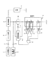
図1は、この発明の実施の形態1を示す低高度衛星用電源装置の構成図である。図1において、1、2、3、5、6、7は図6と同様である。4bは充電用太陽電池9の出力に基づき複数の充電電流を生成し、蓄電池セルが縦続接続された蓄電池5へ異なる複数の充電電流を供給する充電制御器、8は充電用太陽電池9と蓄電池5との間に接続され逆流防止ダイオード、10は蓄電池5と逆流防止ダイオード8との間に接続されたスイッチで、充電開始時はONの状態であり、充電用太陽電池9から直接蓄電池5へ充電が行われる。11は制御用ダイオードである。
なお、充電制御器4bは、充電用太陽電池9の出力に基づく充電電流I1よりレベルの低い充電電流I2、I3(I2>I3)を生成する電流制御部を有している。
12は各蓄電池セルにそれぞれ対応して設けられ、各蓄電池セルの電圧を検出し、かつ当該検出した蓄電池セルの電圧が規定電圧に達した場合、所定の信号を出力する複数のセル電圧検出器、13は上記複数のセル電圧検出器12の出力端に接続され、セル電圧検出器12からの所定信号を上記充電制御器4bへ出力するOR回路である。
【0015】
次にこの発明の動作を以下に説明する。
充電用太陽電池9からの充電電流I1(例えば30A)が図2(a)のI1に示すようにスイッチ10を介して蓄電池5に供給されると、蓄電池5の各蓄電池セルが充電されて各蓄電池セルの電圧が図2(b)のアに示すように上昇する。セル電圧検出器12は蓄電池セルの電圧をそれぞれ検出するが、複数の蓄電池セルのいずれかのセル電圧が規定電圧(例えば3.98V)に達したとき当該セル電圧を検出しているセル電圧検出器12から例えばHighレベルの信号をOR回路13へ出力する。充電制御器4bは上記セル電圧検出器12から出力されたHighレベルの信号をOR回路13を介して入力したときON状態のスイッチ10をOFFに切替える信号を制御用ダイオード11を介してスイッチ10へ出力し、スイッチ10をOFFとする。また充電制御器4bは、全体の蓄電池セル電圧が規定電圧(例えば3.95V×蓄電池セル数)に達したときスイッチ10をOFFにして定電圧充電に移行させるようになっている。
さらに充電制御器4bは、上記充電用太陽電池9からの出力に基づき充電電流I1より低いレベルの充電電流I2、I3( I2>I3)を生成する機能(充電電流I1を充電電流I2、I3に切替える機能)を有し、スイッチ10のOFFと同時に例えば5Aの充電電流I2(図2(a)のI2参照)を蓄電池5に供給し、各蓄電池セルを充電する。この時、各蓄電池セルの充電電圧は、図2(b)のイに示すように初めは減少するが、やがて上昇する。I2の充電電流により各蓄電池セルが充電され、複数の蓄電池セルのうちいずれかのセル電圧が規定電圧(例えば3.98V)に達した場合、これをセル電圧検出器12により検出され、その信号がOR回路13を介して充電制御器4bに入力される。充電制御器4bはセル電圧検出器12からの信号を受けて上記I2をI3の充電電流に切替えて蓄電池5へ図2(a)に示すI3の充電電流(例えば1A)を供給し、各蓄電池セルを充電する(図2(b)のウ参照)。
なお、充電制御器4bは、蓄電池5の放電時にスイッチ10をONに復帰させる信号を制御用ダイオード11を介してスイッチ10へ出力するようになっている。
【0016】
以上のように この発明は、蓄電池に異なる複数の充電電流を供給し、当該充電電流は、最初高いレベルで供給した後、次に低いレベルで供給するようにした多段充電機能を設けたので、充電制御器は充電用太陽電池の電力より低いレベルの充電電流を制御すればよく充電効率が向上するとともに、小型、軽量化できるという効果がある。
また、さらに低レベルの充電電流を設定することにより木目細かく充電制御できる。
【0017】
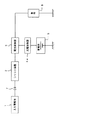
実施の形態2.
図3はこの発明の実施の形態2を示す低高度衛星用電源装置の構成図である。この実施の形態2は、上記実施の形態2の構成のものにシャント回路14を各蓄電池セルに並列に接続し、蓄電池セルの電圧が規定電圧に達した場合、充電電流を規定電圧に達した蓄電池セルに並列接続したシャント回路14にバイパスさせて当該蓄電池セルの電圧上昇を抑えるように構成したところに特徴を有する。
充電電流I3により充電されている場合においてセル電圧検出器12は蓄電池セルの電圧が規定電圧に達していない場合Lowレベルの信号を出力する。シャント回路14はこのLowレベルの信号が出力されている場合はOFF状態となっていて蓄電池セルに充電電流I3が流れる。一方セル電圧検出器12は蓄電池セルの電圧が規定電圧に達した場合Highレベルの信号を出力する。シャント回路14はこのHighレベルの信号によりONとなる。これにより充電電流は規定電圧に達した蓄電池セルに並列接続されたシャント回路14にバイパスされて消費するため、当該蓄電池セルに充電電流I3が流れなくなり電圧上昇を抑制することができる。
【0018】
以上のように この発明は、各蓄電池セル毎に上限電圧制御ができるので、蓄電池セルのサイクル寿命劣化を最小に抑えることができる。
【0019】
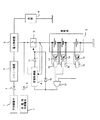
実施の形態3.
図4はこの発明の実施の形態3を示す低高度衛星用電源装置の構成図である。この実施の形態3では、基本的には実施の形態2と同じであるが、実施の形態2と異なるところはOR回路19の出力に基づきスイッチ10をオフする信号を出力する信号ダイオード19と、充電電流I3により充電されている場合において蓄電池全体の電圧をモニターし、当該電圧が規定電圧(充電電流を切替えるための規定電圧より低く設定する)に達した場合は、定電流充電から定電圧充電に移行(切替え)させる機能を有する充電制御器4cを設けたものである。
なお定電圧充電は各蓄電池セル電圧がバランスしているときに生じ、バッテリ動作として理想的な状態である。
【0020】
以上のように この発明は、充電電流I1により充電されている場合の蓄電池全体の電圧をモニターし、当該電圧が規定の電圧(例えば3.95V×蓄電池数)に達したとき、定電流充電から定電圧充電へ切替える機能を充電制御器に持たせ、この機能を多段充電と併用することにより蓄電池セルの電圧特性がバランスしているときにできるだけシャント回路を動作させないで充電制御するようにしたので
規定電圧を低く抑えることができ、蓄電池セルのサイクル寿命劣化を低く抑えることができる。。
【0021】
実施の形態4.
図5はこの発明の実施の形態4を示す低高度衛星用電源装置の構成図である。この実施の形態4では、基本的には実施の形態3と同じであるが、実施の形態3と異なるところは定電流充電から定電圧充電に移行した後、各蓄電池セル電圧にアンバランスが生じた場合、定電圧充電制御を解除し、各蓄電池セル電圧を強制的にシャント回路12が動作するまで(シャント電圧まで)充電電流I3で充電させて各蓄電池セル電圧のバランスをとる機能を有する充電制御器4dを設けたものである。
なお上記各蓄電池セルの電圧はセル電圧検出器12により検出され、OR回路13を介して充電制御器4dに入力され、充電制御器4dにおいて各蓄電池セル電圧にアンバランス(規定電圧に対する各蓄電池セル相互間の電圧のばらつき)の有無を検出するようになっているが、各蓄電池セルの電圧を地上局側でモニターし、上記アンバランスが生じた場合に上記充電制御器4dに対し定電圧充電制御を解除し、各蓄電池セル電圧を強制的にシャント回路12が動作するまで充電電流I3で充電させるためのコマンドを発生するようにしても良い。
【0022】
以上のように、この発明は、定電流充電から定電圧充電に移行した後、各蓄電池セル電圧にアンバランスが生じた場合、定電圧充電制御を解除し、各蓄電池セルを充電電流I3によりシャント動作電圧まで充電することにより、充電のサイクルの進行に伴って生じる各蓄電池セル電圧のアンバランスを是正することができる。
【0023】
なお上記各実施の形態は、低高度衛星用電源装置を例に上げて説明したが、この発明は、他の衛星、電気自動車、地上用太陽発電などにも適用できるものである。
【0024】
【発明の効果】
この発明によれば、異なる充電電流により縦続接続された複数の蓄電池セルを充電(多段充電)することにより蓄電池セルの過充電を抑制することができる。
【0025】
またこの発明は、蓄電池への最低レベルの充電電流供給状態でいずれかの蓄電池セルの電圧が規定の電圧に達した場合、当該蓄電池セルに流れる充電電流を当該蓄電池セルに接続されたシャント回路へバイパスするようにしたので、蓄電池セルの過充電を抑制することができる。
【0026】
この発明は、各蓄電池セルの電圧がバランスしている状態における蓄電池全体の電圧をモニターし、当該電圧が規定電圧に達した場合は、定電流充電から定電圧充電に切替えるようにしたので、サイクル寿命劣化を抑える上でバッテリ動作を理想的な状態にすることができる。
【0027】
またこの発明は、定電流充電から定電圧充電に移行した後、各蓄電池セル電圧にアンバランスが生じた場合、定電圧充電制御を解除し、各蓄電池セルをシャント動作電圧まで充電することにより、各蓄電池セル電圧のアンバランスを是正することができる。
【図面の簡単な説明】
【図1】 この発明の実施の形態1を示す低高度衛星用電源装置の構成図である。
【図2】 この発明の実施の形態1を示す低高度衛星用電源装置の電流、電圧特性を説明するための図である。
【図3】 この発明の実施の形態2を示す低高度衛星用電源装置の構成図である。
【図4】 この発明の実施の形態3を示す低高度衛星用電源装置の構成図である。
【図5】 この発明の実施の形態4を示す低高度衛星用電源装置の構成図である。
【図6】 従来の低高度衛星用電源装置の構成図である。
【図7】 従来の低高度衛星用電源装置の電流、電圧特性を説明するための図である。
【符号の説明】
4 充電制御器 5 蓄電池 9 充電用太陽電池 10 スイッチ 11 制御用ダイオード 12 セル電圧検出器 13 OR回路 14シャント回路 16 信号用ダイオード。[0001]
BACKGROUND OF THE INVENTION
The present invention relates to a battery power storage device used in, for example, a low-altitude satellite power supply device and an electric vehicle power supply device.
Here, for convenience of explanation, a power supply device for a low altitude satellite will be described.
[0002]
FIG. 6 is a configuration diagram of a low-altitude satellite power supply device using a storage battery such as a conventional NiCd (nickel cadmium) battery. In FIG. 6, 1 is a solar cell, 2 is a surplus power generated by the
[0003]
The operation of the conventional low-altitude satellite power supply device will be described below.
The current from the
On the other hand, when the generated power of the
[0004]
[Problems to be solved by the invention]
The charging of the storage battery in the conventional low-altitude satellite power supply device is performed as described above. However, the constant voltage / constant current charging as described above is performed for the entire storage battery in which n storage battery cells are connected in series. Therefore, there has been a problem that a specific cell in the storage battery is overcharged due to an imbalance of charging characteristics of each cell constituting the storage battery. In particular, Li-Ion (lithium ion) cells composed of Li (lithium) electrodes have higher energy density, charging voltage, discharge voltage, etc. than NiCd cells and are expected to be used for storage batteries. In the case of a Li-Ion cell, there is a problem that when the battery is overcharged beyond the specified voltage, the electrode deterioration is promoted and the life is shortened. For example, the constant voltage operating voltage on the VT curve at the temperature To ° C is detected by adding the n cell voltages as the storage battery voltage and comparing with the set voltage. If the cell voltage is higher than the cell voltage due to the internal resistance of the cell, the upper limit voltage of the cell may be exceeded, resulting in deterioration of the cell.
[0005]
This invention is made in order to solve this subject, and it aims at obtaining the battery electrical storage apparatus which can ensure appropriate charge amount without the individual cell which comprises a storage battery being overcharged. .
[0006]
[Means for Solving the Problems]
The battery power storage device according to the first aspect of the invention is different from the storage battery in which the storage battery cells are cascade-connected to the storage battery until a plurality of different charging currents for charging the storage battery are generated from a power supply output, and different specified voltage values are obtained. Charging current generating means having means for supplying a plurality of charging currents.
[0007]
A battery power storage device according to a second invention generates a plurality of different charging currents in the charging current generating means in the first invention, and supplies the charging current at a low level after first supplying the charging current at a high level. Is provided with means for changing the charging current.
[0008]
According to a third aspect of the present invention, in the first and second aspects, the charging current generating means changes the charging current from a high level to a low level when one of the voltages of each storage battery cell reaches a specified voltage. Means are provided.
[0009]
A battery power storage device according to a fourth aspect of the present invention is the first to third aspects of the invention, wherein a shunt circuit is connected to each storage battery cell, and the voltage of any storage battery cell is defined in a state where a minimum charge current is supplied to the storage battery When the voltage is reached, the charging current flowing through the storage battery cell is bypassed to the shunt circuit connected to the storage battery cell.
[0010]
A battery power storage device according to a fifth invention is provided between the power source and the storage battery in the first to fourth inventions, and is normally turned on, and when any of the voltages of the storage battery cells reaches a specified voltage, A switch that is turned off by the charging current generating means and is turned on by discharging is provided.
[0011]
A battery power storage device according to a sixth aspect of the present invention is the first to fifth aspects of the invention, wherein the charging current generating means detects the voltage of the entire storage battery cell, and is charged at a constant voltage when the detected voltage reaches a specified voltage. Means for shifting to control is provided.
[0012]
A battery power storage device according to a seventh aspect of the present invention is the first to sixth aspects of the present invention, wherein the charging current generating means cancels the constant voltage charging control when the plurality of storage battery cell voltages are unbalanced, and the low level charging is performed. Means for charging until a specified voltage is reached with a current is provided.
[0013]
A battery power storage device according to an eighth invention uses a Li-Ion storage battery cell composed of a Li (lithium) electrode as the storage battery cell in the first to seventh inventions.
[0014]
DETAILED DESCRIPTION OF THE INVENTION
FIG. 1 is a configuration diagram of a low-altitude satellite power supply apparatus according to
The charge controller 4b includes a current control unit that generates charging currents I2 and I3 (I2> I3) that are lower in level than the charging current I1 based on the output of the charging solar cell 9.
A plurality of
[0015]
Next, the operation of the present invention will be described below.
When a charging current I1 (for example, 30 A) from the charging solar battery 9 is supplied to the
Further, the charging controller 4b generates a charging current I2, I3 (I2> I3) at a level lower than the charging current I1 based on the output from the charging solar cell 9 (the charging current I1 is changed to the charging currents I2, I3). For example, 5 A of charging current I2 (see I2 in FIG. 2A) is supplied to the
The charging controller 4 b outputs a signal for returning the
[0016]
As described above, the present invention provides a multi-stage charging function in which a plurality of different charging currents are supplied to a storage battery, and the charging current is supplied at the first high level and then at the next lower level. The charging controller only needs to control a charging current at a level lower than the power of the charging solar cell, and the charging efficiency is improved, and there is an effect that it can be reduced in size and weight.
In addition, finer charge control can be performed by setting a lower level charge current.
[0017]
FIG. 3 is a configuration diagram of a low-altitude satellite power supply
In the case where the battery is charged with the charging current I3, the
[0018]
As described above, according to the present invention, the upper limit voltage can be controlled for each storage battery cell, so that the cycle life deterioration of the storage battery cell can be minimized.
[0019]
FIG. 4 is a configuration diagram of a low-altitude satellite power supply
The constant voltage charging occurs when the storage battery cell voltages are balanced, and is an ideal state for battery operation.
[0020]
As described above, the present invention monitors the voltage of the entire storage battery when it is charged with the charging current I1, and from the constant current charging when the voltage reaches a specified voltage (eg, 3.95V × the number of storage batteries). Since the charge controller has a function to switch to constant voltage charging, and this function is used in combination with multistage charging, charging control is performed without operating the shunt circuit as much as possible when the voltage characteristics of the storage battery cells are balanced. The specified voltage can be kept low, and the cycle life deterioration of the storage battery cell can be kept low. .
[0021]
FIG. 5 is a configuration diagram of a low-altitude satellite power supply
The voltage of each storage battery cell is detected by the
[0022]
As described above, the present invention cancels the constant voltage charging control when each storage battery cell voltage is unbalanced after shifting from constant current charging to constant voltage charging, and shunts each storage battery cell with the charging current I3. By charging up to the operating voltage, it is possible to correct the imbalance of each battery cell voltage that occurs as the charging cycle progresses.
[0023]
Each of the above embodiments has been described by taking the power supply device for a low altitude satellite as an example, but the present invention can also be applied to other satellites, electric vehicles, terrestrial solar power generation, and the like.
[0024]
【The invention's effect】
According to this invention, the overcharge of a storage battery cell can be suppressed by charging the several storage battery cell cascade-connected by different charging current (multistage charging).
[0025]
Further, according to the present invention, when the voltage of any of the storage battery cells reaches a specified voltage in a state where the charging current is supplied to the storage battery at the lowest level, the charging current flowing through the storage battery cell is transferred to the shunt circuit connected to the storage battery cell. Since it bypasses, the overcharge of a storage battery cell can be suppressed.
[0026]
The present invention monitors the voltage of the entire storage battery in a state where the voltages of the storage battery cells are balanced, and when the voltage reaches a specified voltage, the constant current charging is switched to the constant voltage charging. The battery operation can be brought into an ideal state in order to suppress the life deterioration.
[0027]
Moreover, this invention, after shifting from constant current charging to constant voltage charging, when an imbalance occurs in each storage battery cell voltage, by releasing the constant voltage charging control and charging each storage battery cell to the shunt operating voltage, Unbalance of each battery cell voltage can be corrected.
[Brief description of the drawings]
FIG. 1 is a configuration diagram of a low-altitude satellite power supply apparatus according to
FIG. 2 is a diagram for explaining current and voltage characteristics of a low-altitude satellite power supply device according to
FIG. 3 is a configuration diagram of a low-altitude satellite power supply apparatus according to
FIG. 4 is a configuration diagram of a low-altitude satellite power supply apparatus according to
FIG. 5 is a configuration diagram of a low-altitude satellite power supply apparatus according to
FIG. 6 is a configuration diagram of a conventional low-altitude satellite power supply device.
FIG. 7 is a diagram for explaining current and voltage characteristics of a conventional low-altitude satellite power supply device.
[Explanation of symbols]
4
Claims (6)
電源の出力電流に基づいて上記蓄電池を充電するための充電電流を生成する充電制御手段と、
上記電源と蓄電池の間に接続されたスイッチと、を備え、
上記充電制御手段は、
上記スイッチの接続がON状態にて、上記各蓄電池セルの電圧のいずれかが規定電圧に達したときに上記スイッチの接続をOFF状態とした後、
上記いずれかの蓄電池セルの電圧が規定電圧に達した場合、生成する充電電流を高いレベルから低いレベルに変化させて上記蓄電池に供給し、
上記蓄電池全体の電圧が規定電圧に達したときに上記蓄電池を定電圧充電制御する、
ことを特徴とするバッテリ蓄電装置。A storage battery in which a plurality of storage battery cells are connected in cascade;
Charging control means for generating a charging current for charging the storage battery based on an output current of a power source;
A switch connected between the power source and the storage battery,
The charge control means includes
After the switch connection is turned on, when any of the voltages of the storage battery cells reaches a specified voltage, the switch connection is turned off .
When the voltage of any one of the storage battery cells reaches a specified voltage, the charging current to be generated is changed from a high level to a low level and supplied to the storage battery ,
When the voltage of the entire storage battery reaches a specified voltage, the storage battery is controlled at a constant voltage,
A battery power storage device.
上記充電制御手段は、上記電源を構成する充電用電源の出力に基づいて当該充電用電源の電力より低いレベルの充電電流を生成することを特徴とする請求項1から請求項3のいずれかに記載のバッテリ蓄電装置。Power control means for supplying power generated by a main power source constituting the power source to the storage battery, and for controlling the charge control means to discharge the storage battery when the generated power of the main power source decreases. Prepared,
The charging control means generates a charging current at a level lower than the power of the charging power source based on the output of the charging power source constituting the power source. The battery power storage device described.
電源出力から上記蓄電池を充電するための充電電流を生成する充電制御手段と、
上記各蓄電池セルにそれぞれ接続され、いずれかの蓄電池セルの電圧がシャント電圧に達した場合、当該蓄電池セルに流れる充電電流をそれぞれバイパスするシャント回路と、を備え、
上記充電制御手段は、
上記いずれかの蓄電池セルの電圧が規定電圧に達した場合、充電電流を高いレベルから低いレベルに変化させるとともに、
当該低いレベルの充電電流にて充電されている場合に、上記蓄電池全体の電圧が規定電圧に達したときに上記蓄電池を定電圧充電制御し、
上記各蓄電池セルの電圧のモニタ結果に基づいて当該各蓄電池セルのセル電圧がアンバランスになったときに上記定電圧充電制御を解除し、上記低いレベルの充電電流で全ての蓄電池セル電圧がシャント電圧に達するまで充電電流を供給する、
ことを特徴とするバッテリ蓄電装置。A storage battery in which a plurality of storage battery cells are connected in cascade;
Charging control means for generating a charging current for charging the storage battery from a power output;
A shunt circuit that is connected to each of the storage battery cells and bypasses a charging current flowing through the storage battery cell when the voltage of any of the storage battery cells reaches a shunt voltage;
The charge control means includes
When the voltage of any of the above storage battery cells reaches a specified voltage, the charging current is changed from a high level to a low level,
When charging with the low level charging current, when the voltage of the entire storage battery reaches a specified voltage, the storage battery is controlled at a constant voltage,
The constant voltage charging control is canceled when the cell voltage of each storage battery cell becomes unbalanced based on the monitoring result of the voltage of each storage battery cell, and all storage battery cell voltages are shunted at the low level charging current. Supply charging current until the voltage is reached,
A battery power storage device.
(リチウムイオン)蓄電池セルを用いたことを特徴とする請求項1〜5のいずれか記載のバッテリ蓄電装置。The above storage battery cell is composed of Li-Ion electrodes
The battery power storage device according to claim 1, wherein a (lithium ion) storage battery cell is used.
Priority Applications (5)
| Application Number | Priority Date | Filing Date | Title |
|---|---|---|---|
| JP15779799A JP3736205B2 (en) | 1999-06-04 | 1999-06-04 | Battery power storage device |
| US09/443,286 US6373224B1 (en) | 1999-06-04 | 1999-11-19 | Battery accumulating apparatus |
| FR9915100A FR2794578B1 (en) | 1999-06-04 | 1999-11-30 | BATTERY ACCUMULATION DEVICE |
| EP00108803A EP1058367B1 (en) | 1999-06-04 | 2000-04-26 | Battery accumulating apparatus |
| CA002310357A CA2310357C (en) | 1999-06-04 | 2000-05-31 | Battery accumulating apparatus |
Applications Claiming Priority (1)
| Application Number | Priority Date | Filing Date | Title |
|---|---|---|---|
| JP15779799A JP3736205B2 (en) | 1999-06-04 | 1999-06-04 | Battery power storage device |
Publications (3)
| Publication Number | Publication Date |
|---|---|
| JP2000350378A JP2000350378A (en) | 2000-12-15 |
| JP2000350378A5 JP2000350378A5 (en) | 2004-12-24 |
| JP3736205B2 true JP3736205B2 (en) | 2006-01-18 |
Family
ID=15657506
Family Applications (1)
| Application Number | Title | Priority Date | Filing Date |
|---|---|---|---|
| JP15779799A Expired - Fee Related JP3736205B2 (en) | 1999-06-04 | 1999-06-04 | Battery power storage device |
Country Status (5)
| Country | Link |
|---|---|
| US (1) | US6373224B1 (en) |
| EP (1) | EP1058367B1 (en) |
| JP (1) | JP3736205B2 (en) |
| CA (1) | CA2310357C (en) |
| FR (1) | FR2794578B1 (en) |
Families Citing this family (50)
| Publication number | Priority date | Publication date | Assignee | Title |
|---|---|---|---|---|
| JP2002186192A (en) | 2000-12-18 | 2002-06-28 | Mitsubishi Electric Corp | Battery charger |
| US8431264B2 (en) | 2002-08-09 | 2013-04-30 | Infinite Power Solutions, Inc. | Hybrid thin-film battery |
| US8404376B2 (en) | 2002-08-09 | 2013-03-26 | Infinite Power Solutions, Inc. | Metal film encapsulation |
| US8394522B2 (en) | 2002-08-09 | 2013-03-12 | Infinite Power Solutions, Inc. | Robust metal film encapsulation |
| US9793523B2 (en) | 2002-08-09 | 2017-10-17 | Sapurast Research Llc | Electrochemical apparatus with barrier layer protected substrate |
| US8021778B2 (en) | 2002-08-09 | 2011-09-20 | Infinite Power Solutions, Inc. | Electrochemical apparatus with barrier layer protected substrate |
| US8445130B2 (en) | 2002-08-09 | 2013-05-21 | Infinite Power Solutions, Inc. | Hybrid thin-film battery |
| US20070264564A1 (en) | 2006-03-16 | 2007-11-15 | Infinite Power Solutions, Inc. | Thin film battery on an integrated circuit or circuit board and method thereof |
| US8236443B2 (en) | 2002-08-09 | 2012-08-07 | Infinite Power Solutions, Inc. | Metal film encapsulation |
| US8728285B2 (en) | 2003-05-23 | 2014-05-20 | Demaray, Llc | Transparent conductive oxides |
| TWI253195B (en) * | 2003-12-26 | 2006-04-11 | Ind Tech Res Inst | Charging method and system for serially connected batteries |
| DE602005017512D1 (en) | 2004-12-08 | 2009-12-17 | Symmorphix Inc | DEPOSIT OF LICOO2 |
| US7959769B2 (en) | 2004-12-08 | 2011-06-14 | Infinite Power Solutions, Inc. | Deposition of LiCoO2 |
| JP2007014163A (en) * | 2005-07-01 | 2007-01-18 | Fujitsu Ltd | Charging ic, charger and electronic apparatus |
| JP2007097330A (en) * | 2005-09-29 | 2007-04-12 | Kyocera Corp | Charger and terminal apparatus |
| US7509688B2 (en) * | 2005-10-20 | 2009-03-31 | Steven Ross Gregg | Facial hair trimmings catcher |
| WO2008039471A2 (en) | 2006-09-29 | 2008-04-03 | Infinite Power Solutions, Inc. | Masking of and material constraint for depositing battery layers on flexible substrates |
| US8197781B2 (en) | 2006-11-07 | 2012-06-12 | Infinite Power Solutions, Inc. | Sputtering target of Li3PO4 and method for producing same |
| US20080218127A1 (en) * | 2007-03-07 | 2008-09-11 | O2Micro Inc. | Battery management systems with controllable adapter output |
| KR101407941B1 (en) | 2007-04-16 | 2014-06-18 | 한라비스테온공조 주식회사 | Solar cell system for Vehicles and its control method |
| WO2009001502A1 (en) * | 2007-06-22 | 2008-12-31 | Panasonic Corporation | Nonaqueous secondary battery, battery pack, power supply system, and electrical device |
| JP2009032668A (en) * | 2007-06-22 | 2009-02-12 | Panasonic Corp | Nonaqueous secondary battery, battery pack, power source system, and electrically powered equipment |
| KR100998302B1 (en) | 2007-12-07 | 2010-12-06 | 삼성에스디아이 주식회사 | Method for charging of secondary battery and charging device |
| US8268488B2 (en) * | 2007-12-21 | 2012-09-18 | Infinite Power Solutions, Inc. | Thin film electrolyte for thin film batteries |
| TWI441937B (en) | 2007-12-21 | 2014-06-21 | Infinite Power Solutions Inc | Method for sputter targets for electrolyte films |
| KR101606183B1 (en) | 2008-01-11 | 2016-03-25 | 사푸라스트 리써치 엘엘씨 | Thin film encapsulation for thin film batteries and other devices |
| KR101672254B1 (en) * | 2008-04-02 | 2016-11-08 | 사푸라스트 리써치 엘엘씨 | Passive over/under voltage control and protection for energy storage devices associated with energy harvesting |
| US20100026240A1 (en) * | 2008-07-30 | 2010-02-04 | 3M Innovative Properties Company | Lithium ion battery pack charging system and device including the same |
| CN102119454B (en) | 2008-08-11 | 2014-07-30 | 无穷动力解决方案股份有限公司 | Energy device with integral collector surface for electromagnetic energy harvesting and method thereof |
| JP2010068571A (en) * | 2008-09-09 | 2010-03-25 | Hitachi Koki Co Ltd | Charging apparatus |
| KR101613671B1 (en) | 2008-09-12 | 2016-04-19 | 사푸라스트 리써치 엘엘씨 | Energy device with integral conductive surface for data communication via electromagnetic energy and method thereof |
| US8508193B2 (en) | 2008-10-08 | 2013-08-13 | Infinite Power Solutions, Inc. | Environmentally-powered wireless sensor module |
| CN101953015A (en) * | 2009-01-07 | 2011-01-19 | 松下电器产业株式会社 | Battery set charging method and battery charging system |
| US20100231162A1 (en) * | 2009-03-16 | 2010-09-16 | Gm Global Technology Operations, Inc. | Solar powered battery charging methods and devices for lithium-ion battery systems |
| US8599572B2 (en) | 2009-09-01 | 2013-12-03 | Infinite Power Solutions, Inc. | Printed circuit board with integrated thin film battery |
| JP5525862B2 (en) * | 2010-02-26 | 2014-06-18 | 三洋電機株式会社 | Charger, program |
| JP5489779B2 (en) * | 2010-02-26 | 2014-05-14 | 株式会社Nttファシリティーズ | Lithium-ion battery charging system and charging method |
| US9722334B2 (en) * | 2010-04-07 | 2017-08-01 | Black & Decker Inc. | Power tool with light unit |
| US20110300432A1 (en) | 2010-06-07 | 2011-12-08 | Snyder Shawn W | Rechargeable, High-Density Electrochemical Device |
| JP5541982B2 (en) * | 2010-06-28 | 2014-07-09 | シャープ株式会社 | DC power distribution system |
| TWM402554U (en) * | 2010-11-10 | 2011-04-21 | Richtek Technology Corp | Charger circuit |
| JP2012222837A (en) * | 2011-04-04 | 2012-11-12 | Toshiba Mitsubishi-Electric Industrial System Corp | Secondary battery charge control system |
| DE102011017599A1 (en) * | 2011-04-27 | 2012-10-31 | Robert Bosch Gmbh | Method for operating a storage device for storing electrical energy and storage device for storing electrical energy |
| EP2724445A4 (en) * | 2011-06-21 | 2015-09-30 | Husqvarna Ab | System and method for charging of a rechargeable battery |
| DE102011121940A1 (en) * | 2011-12-22 | 2013-06-27 | Andreas Stihl Ag & Co. Kg | Debalancing protection circuit for a battery pack |
| US8981709B1 (en) * | 2012-08-22 | 2015-03-17 | Edee, LLC | Supplemental electrical generation apparatus and method |
| US9156359B2 (en) | 2012-09-28 | 2015-10-13 | GM Global Technology Operations LLC | Methods and vehicle systems for selectively using energy obtained from a solar subsystem |
| CN103023112B (en) * | 2012-12-18 | 2015-09-09 | 北车风电有限公司 | The back-up source charging device of wind generating set pitch control system and charging method |
| FR3033674B1 (en) | 2015-03-10 | 2018-04-06 | Sunna Design | ELECTRONIC CONTROL BOARD OF ENERGY CONTROL OF AUTONOMOUS AND COMMUNICABLE ELECTRICAL EQUIPMENT |
| JP7200512B2 (en) * | 2018-06-21 | 2023-01-10 | カシオ計算機株式会社 | ELECTRONIC DEVICE, ELECTRONIC WATCH AND BATTERY CHARGING METHOD |
Family Cites Families (26)
| Publication number | Priority date | Publication date | Assignee | Title |
|---|---|---|---|---|
| US4079303A (en) | 1976-07-28 | 1978-03-14 | The United States Of America As Represented By The United States Department Of Energy | Charging system and method for multicell storage batteries |
| US4270080A (en) | 1978-12-14 | 1981-05-26 | Sun Electric Corporation | Automatic battery charge apparatus and method |
| JPS5972941A (en) | 1982-10-20 | 1984-04-25 | 日本電気株式会社 | Storage battery charging controller |
| JP3231801B2 (en) * | 1991-02-08 | 2001-11-26 | 本田技研工業株式会社 | Battery charger |
| JPH06133465A (en) | 1992-08-27 | 1994-05-13 | Sanyo Electric Co Ltd | Method and apparatus for charging secondary battery |
| JPH06165399A (en) | 1992-11-24 | 1994-06-10 | Nippon Moriseru Kk | Charger for lithium ion secondary cell |
| US5367244A (en) * | 1993-01-19 | 1994-11-22 | Premier Engineered Products, Inc. | Battery charging method with stepped current profile and associated charger |
| US5530335A (en) * | 1993-05-11 | 1996-06-25 | Trw Inc. | Battery regulated bus spacecraft power control system |
| JP3577751B2 (en) | 1993-12-24 | 2004-10-13 | ソニー株式会社 | Battery charging device, battery pack, and battery charging method |
| US5550453A (en) | 1994-01-24 | 1996-08-27 | Motorola, Inc. | Battery charging method and apparatus |
| FR2725849B1 (en) * | 1994-10-18 | 1996-12-20 | Accumulateurs Fixes | METHOD FOR REGULATING THE CHARGE OF AN ELECTRIC BATTERY ASSEMBLY AND ARRANGEMENT USING THE SAME |
| CA2169706A1 (en) * | 1995-03-03 | 1996-09-04 | Troy Lynn Stockstad | Circuit and method for battery charge control |
| JPH0997629A (en) | 1995-09-29 | 1997-04-08 | Sanyo Electric Co Ltd | Plural lithium ion secondary battery charging method |
| JP3620118B2 (en) | 1995-10-24 | 2005-02-16 | 松下電器産業株式会社 | Constant current / constant voltage charger |
| JP3629791B2 (en) * | 1996-01-17 | 2005-03-16 | 日産自動車株式会社 | Charge control device for battery pack |
| GB9605830D0 (en) | 1996-03-20 | 1996-05-22 | Atomic Energy Authority Uk | Cell overcharge prevention |
| JPH09308126A (en) | 1996-05-17 | 1997-11-28 | Nissan Motor Co Ltd | Charger |
| US5729116A (en) * | 1996-12-20 | 1998-03-17 | Total Battery Management, Inc. | Shunt recognition in lithium batteries |
| JP3884802B2 (en) | 1996-11-07 | 2007-02-21 | 日産自動車株式会社 | Lithium-ion battery charging method |
| JPH10191574A (en) * | 1996-12-26 | 1998-07-21 | Japan Tobacco Inc | Charging equipment |
| JPH10248177A (en) | 1997-03-03 | 1998-09-14 | Sanyo Electric Co Ltd | Charging circuit |
| US5804944A (en) | 1997-04-07 | 1998-09-08 | Motorola, Inc. | Battery protection system and process for charging a battery |
| US5952815A (en) * | 1997-07-25 | 1999-09-14 | Minnesota Mining & Manufacturing Co. | Equalizer system and method for series connected energy storing devices |
| JPH1189106A (en) | 1997-09-08 | 1999-03-30 | Central Res Inst Of Electric Power Ind | Multi-stage charging method/device for secondary battery |
| US6034506A (en) * | 1998-01-16 | 2000-03-07 | Space Systems/Loral, Inc. | Lithium ion satellite battery charge control circuit |
| JP2000236631A (en) | 1999-02-17 | 2000-08-29 | Nec Corp | Battery charge control circuit |
-
1999
- 1999-06-04 JP JP15779799A patent/JP3736205B2/en not_active Expired - Fee Related
- 1999-11-19 US US09/443,286 patent/US6373224B1/en not_active Expired - Fee Related
- 1999-11-30 FR FR9915100A patent/FR2794578B1/en not_active Expired - Fee Related
-
2000
- 2000-04-26 EP EP00108803A patent/EP1058367B1/en not_active Expired - Lifetime
- 2000-05-31 CA CA002310357A patent/CA2310357C/en not_active Expired - Fee Related
Also Published As
| Publication number | Publication date |
|---|---|
| FR2794578A1 (en) | 2000-12-08 |
| EP1058367A2 (en) | 2000-12-06 |
| FR2794578B1 (en) | 2003-10-17 |
| US6373224B1 (en) | 2002-04-16 |
| CA2310357C (en) | 2004-02-17 |
| CA2310357A1 (en) | 2000-12-04 |
| JP2000350378A (en) | 2000-12-15 |
| EP1058367B1 (en) | 2011-06-15 |
| EP1058367A3 (en) | 2002-11-20 |
Similar Documents
| Publication | Publication Date | Title |
|---|---|---|
| JP3736205B2 (en) | Battery power storage device | |
| US6373226B1 (en) | Method of controlling discharge of a plurality of rechargeable batteries, and battery assembly | |
| US8054044B2 (en) | Apparatus and method for balancing of battery cell'S charge capacity | |
| KR101124803B1 (en) | Charge Equalization Apparatus and Method | |
| KR100885291B1 (en) | Electric charger | |
| US8531157B2 (en) | Charging apparatus having overcharge protection and charging method for the same | |
| JP5488877B2 (en) | Electric tool | |
| JP3931446B2 (en) | Battery charge state adjustment device | |
| US9413037B2 (en) | Cell capacity adjusting device | |
| US20210399558A1 (en) | Battery control unit and battery system | |
| US11843267B2 (en) | Battery control unit and battery system | |
| KR20060078967A (en) | Balance charging control method of 2nd-series battery pack | |
| JP2010110156A (en) | Pack battery | |
| JP3755043B2 (en) | Chargeable / dischargeable power supply | |
| JP3629791B2 (en) | Charge control device for battery pack | |
| JP2001008373A (en) | Battery unit and charging method of battery | |
| JPH08140278A (en) | Charging/discharging protector for battery pack | |
| JP2000166103A (en) | Charging discharging control method | |
| JP2003158827A (en) | Charging method, charging device, and discharging controller for lithium ion battery | |
| US11581747B2 (en) | Power supply device | |
| JPH10313544A (en) | Overcharge preventing circuit, overdischarge preventing circuit and charge/discharge control circuit | |
| WO2021241136A1 (en) | Backup power supply device | |
| KR20120015861A (en) | Method for cell balancing using sub-cell | |
| JP5775324B2 (en) | Battery system | |
| KR20160008106A (en) | Active balancing apparatus for balancing battery cell voltage |
Legal Events
| Date | Code | Title | Description |
|---|---|---|---|
| A521 | Written amendment |
Free format text: JAPANESE INTERMEDIATE CODE: A523 Effective date: 20040120 |
|
| A621 | Written request for application examination |
Free format text: JAPANESE INTERMEDIATE CODE: A621 Effective date: 20040120 |
|
| RD01 | Notification of change of attorney |
Free format text: JAPANESE INTERMEDIATE CODE: A7421 Effective date: 20040624 |
|
| A977 | Report on retrieval |
Free format text: JAPANESE INTERMEDIATE CODE: A971007 Effective date: 20050413 |
|
| A131 | Notification of reasons for refusal |
Free format text: JAPANESE INTERMEDIATE CODE: A131 Effective date: 20050419 |
|
| A521 | Written amendment |
Free format text: JAPANESE INTERMEDIATE CODE: A523 Effective date: 20050613 |
|
| A131 | Notification of reasons for refusal |
Free format text: JAPANESE INTERMEDIATE CODE: A131 Effective date: 20050712 |
|
| A521 | Written amendment |
Free format text: JAPANESE INTERMEDIATE CODE: A523 Effective date: 20050909 |
|
| TRDD | Decision of grant or rejection written | ||
| A01 | Written decision to grant a patent or to grant a registration (utility model) |
Free format text: JAPANESE INTERMEDIATE CODE: A01 Effective date: 20051004 |
|
| A61 | First payment of annual fees (during grant procedure) |
Free format text: JAPANESE INTERMEDIATE CODE: A61 Effective date: 20051017 |
|
| FPAY | Renewal fee payment (event date is renewal date of database) |
Free format text: PAYMENT UNTIL: 20081104 Year of fee payment: 3 |
|
| FPAY | Renewal fee payment (event date is renewal date of database) |
Free format text: PAYMENT UNTIL: 20091104 Year of fee payment: 4 |
|
| FPAY | Renewal fee payment (event date is renewal date of database) |
Free format text: PAYMENT UNTIL: 20091104 Year of fee payment: 4 |
|
| FPAY | Renewal fee payment (event date is renewal date of database) |
Free format text: PAYMENT UNTIL: 20101104 Year of fee payment: 5 |
|
| FPAY | Renewal fee payment (event date is renewal date of database) |
Free format text: PAYMENT UNTIL: 20111104 Year of fee payment: 6 |
|
| FPAY | Renewal fee payment (event date is renewal date of database) |
Free format text: PAYMENT UNTIL: 20121104 Year of fee payment: 7 |
|
| FPAY | Renewal fee payment (event date is renewal date of database) |
Free format text: PAYMENT UNTIL: 20121104 Year of fee payment: 7 |
|
| FPAY | Renewal fee payment (event date is renewal date of database) |
Free format text: PAYMENT UNTIL: 20131104 Year of fee payment: 8 |
|
| LAPS | Cancellation because of no payment of annual fees |