JP3735471B2 - Packet relay device and LSI - Google Patents
Packet relay device and LSI Download PDFInfo
- Publication number
- JP3735471B2 JP3735471B2 JP28220598A JP28220598A JP3735471B2 JP 3735471 B2 JP3735471 B2 JP 3735471B2 JP 28220598 A JP28220598 A JP 28220598A JP 28220598 A JP28220598 A JP 28220598A JP 3735471 B2 JP3735471 B2 JP 3735471B2
- Authority
- JP
- Japan
- Prior art keywords
- address
- node
- route
- packet
- search
- Prior art date
- Legal status (The legal status is an assumption and is not a legal conclusion. Google has not performed a legal analysis and makes no representation as to the accuracy of the status listed.)
- Expired - Lifetime
Links
Images


Classifications
-
- H—ELECTRICITY
- H04—ELECTRIC COMMUNICATION TECHNIQUE
- H04L—TRANSMISSION OF DIGITAL INFORMATION, e.g. TELEGRAPHIC COMMUNICATION
- H04L45/00—Routing or path finding of packets in data switching networks
- H04L45/74—Address processing for routing
- H04L45/742—Route cache; Operation thereof
-
- H—ELECTRICITY
- H04—ELECTRIC COMMUNICATION TECHNIQUE
- H04L—TRANSMISSION OF DIGITAL INFORMATION, e.g. TELEGRAPHIC COMMUNICATION
- H04L12/00—Data switching networks
- H04L12/02—Details
- H04L12/16—Arrangements for providing special services to substations
- H04L12/18—Arrangements for providing special services to substations for broadcast or conference, e.g. multicast
-
- H—ELECTRICITY
- H04—ELECTRIC COMMUNICATION TECHNIQUE
- H04L—TRANSMISSION OF DIGITAL INFORMATION, e.g. TELEGRAPHIC COMMUNICATION
- H04L12/00—Data switching networks
- H04L12/28—Data switching networks characterised by path configuration, e.g. LAN [Local Area Networks] or WAN [Wide Area Networks]
- H04L12/46—Interconnection of networks
-
- H—ELECTRICITY
- H04—ELECTRIC COMMUNICATION TECHNIQUE
- H04L—TRANSMISSION OF DIGITAL INFORMATION, e.g. TELEGRAPHIC COMMUNICATION
- H04L45/00—Routing or path finding of packets in data switching networks
-
- H—ELECTRICITY
- H04—ELECTRIC COMMUNICATION TECHNIQUE
- H04L—TRANSMISSION OF DIGITAL INFORMATION, e.g. TELEGRAPHIC COMMUNICATION
- H04L45/00—Routing or path finding of packets in data switching networks
- H04L45/16—Multipoint routing
Landscapes
- Engineering & Computer Science (AREA)
- Computer Networks & Wireless Communication (AREA)
- Signal Processing (AREA)
- Data Exchanges In Wide-Area Networks (AREA)
- Small-Scale Networks (AREA)
- Computer And Data Communications (AREA)
- Communication Control (AREA)
Description
【0001】
【発明の属する技術分野】
本発明は、複数のネットワークを相互に接続し、パケットを中継するパケット中継装置、特にマルチキャストパケットの次転送先検索方式に関する。
【0002】
【従来の技術】
ユーザの増加に伴い、インターネットを流れるトラフィック(パケット)が急増し、インターネットが大規模化・高速化している。また、現在のインターネット(Internet Protocolによるパケット通信網:以下IPネットワーク)では、従来のデータ系の通信だけでなく、インターネット電話やインターネット放送などのリアルタイム系アプリケーション(用途)も登場し、音声通信機能の取り込みや、放送機能の取り込みが進んでいる。このような状況下において、IPネットワークにおけるIPマルチキャスト技術は、インターネットにおける動画や音声やコンテンツなどのマルチメディアデータの配信に有効な技術として期待されている。また、IPネットワークを構成するパケット中継装置(ルータ)におけるIPマルチキャスト技術のサポート、IPマルチキャスト技術の高速化が課題となっている。
【0003】
ルータは、ある端末から特定の一つの端末にパケットを送信するユニキャスト通信の場合、受信パケットのヘッダ内の宛先IPアドレスに対応する経路情報(次に転送すべきルータあるいは端末のIPアドレス、およびルータ内の送信ポート番号)をルーティングテーブルから検索し、パケットを送信する。以下、ユニキャストの経路検索について簡単に説明する。
【0004】
ルーティングテーブルは、宛先IPアドレスに対応するサブネットワークアドレスとサブネットマスク長および、上記の経路情報から構成される情報群を複数保持している。以下では、これらの情報群をエントリと呼ぶ。ここでサブネットワークとは、例えば宛先の企業網の様な端末の部分集合を示し、サブネットワークアドレスは部分集合のIPアドレスをアドレス情報として結合したアドレス群である。また、サブネットマスク長はIPアドレスのうち上位何ビットが上記のサブネットワークの識別子であるかを示す値である。ルータは、受信パケットの宛先IPアドレスにエントリ内のサブネットマスク長だけ上位ビットから有効なマスクをかけたものとエントリのサブネットワークアドレスを比較して、一致するエントリの経路情報を検索結果とする。このようにサブネットワーク単位でエントリを構成することによりルーティングテーブルのエントリ数を大幅に縮小し、検索処理の効率化を図っている。複数のエントリに一致した場合は、サブネットマスク長が最長のエントリの経路情報を検索結果とする。以下では、この検索方式を最長一致検索と呼ぶ。
【0005】
ある端末から特定の複数の端末にパケットを送信するマルチキャスト通信の場合、ルーティングテーブルの各エントリは、送信元サブネットアドレスとアドレスマスクとマルチキャストグループアドレス、および経路情報から構成される。マルチキャスト・グループアドレスとは、送信元がパケットを送信すべき複数の宛先の集合(以下、マルチキャストグループと呼ぶ。)に対して割り当てられる識別子である。ルータは、受信パケットのヘッダ内の送信元IPアドレスと受信パケットのヘッダ内の宛先IPアドレス部に入っているマルチキャスト・グループアドレスをキーにして、ルーティングテーブルを検索する。マルチキャストの場合、検索の結果一致したエントリの経路情報は複数の送信ポート番号から構成される。ルータはこの送信ポート番号に従い、受信パケットをコピー処理して、上記特定のマルチキャストグループ向けに出力する。これらの検索処理やコピー処理の負荷が重く、マルチキャスト通信の性能が低いと、マルチキャストパケットを転送処理するルータ全体の性能低下の要因となってしまう。このため、通常のユニキャストパケット中継処理と同様に高速化が要求されている。
【0006】
ルータの負荷分散処理方式による高速化に関しては、例えば特開平6−197111号公報(以下「従来技術1」という。)に言及がある。従来技術1では、負荷分散処理方式により、高速中継可能なルータを実現することを目的としている。パケット中継を行うパケット中継モジュールがバスにより複数接続され、各々が同じくバスに接続された管理部からのルーティングテーブル情報に基づいてパケット中継機能を行う。パケット中継モジュールの増設により、性能向上ができる。さらに、従来技術1のパケット中継モジュールは、受信パケットのヘッダを抽出し、パケット転送先の検索処理を行うルーティング処理部と、受信パケットをメモリに格納し、上記解析結果に基づいて対応する他のパケット中継モジュールに受信パケットを転送する転送処理部を備え、別々の処理部で機能分担処理させることでパケット中継処理の高速化を図っている。しかし、従来技術1では、マルチキャストパケットの中継処理の高速化に関しては記載がない。
【0007】
ルータにおけるマルチキャストパケットの宛先の検索(以下、マルチキャスト経路検索と呼ぶ)に関しては、例えば、(以下「従来技術2」という。)に記載されている。従来技術2では、ルーティングテーブル検索をハッシュ検索方式を用いることにより高速化している。ルーティングテーブル情報をそのまま検索すると、対象となる宛先IPアドレスが増加しテーブルのエントリが増加するに従って、検索処理にかかる検索時間が著しく増加してしまう。従来技術2は、ハッシュ値を計算するためのキーとして受信パケット内の送信元IPアドレスを使用しており、ハッシュ値が等しい宛先IPアドレスに対するエントリをグループ化したルーティングテーブル群を備える。
【0008】
マルチキャストパケット受信時には、ルータ内部の経路検索処理部は、受信パケットの送信元IPアドレスからハッシュ値を計算し、該ハッシュ値に対応する上記ルーティングテーブルを検索する。ハッシュ値に従ってルーティングテーブルの検索範囲を限定することで経路検索の高速化を図っている。
【0009】
一方、経路検索方式としてRadishアルゴリズムが知られている。Radishアルゴリズムに関しては、例えば"A technical memo of WIDE project, Kazuhiko Yamamoto, Akira Kato and Akira Watanabe,Radish−A Simple Table Structure for CIDR"(以下「従来技術3」という。)に記載されている。
【0010】
このRadish方式のルーティングテーブルは、エントリを2分木構造に構成し、検索を高速化している。具体的には、IPアドレス形式の最上位ビットをルート(木構造の根)側とする左右にポインタを持つ複数の頂点(ノード)をポインタでつないだ2分木構造の各ノードにエントリを割り付けて構成している。この2分木構造を検索する際には、受信パケットの宛先IPアドレスを上位ビットから1ビットづつ検査し、検査されたビットの値(0または1)に従って各ノードの左右のどちらかのポインタを選択して次のノードに移動する。このような検索により目的のエントリが割り付けられたノードにたどり着くことができる。
【0011】
従来技術3は、宛先IPアドレスを1ビットずつ検査して2分木を辿るため、ルーティングテーブルのエントリが多くなっても、高々宛先IPアドレスのビット数回の検査を行う(2分木ノードを辿る)ことで検索を終了することができる。
【0012】
上記のユニキャストの経路検索の説明で述べた、マスク長の異なる複数のエントリにマッチする場合、従来技術3のRadish方式のルーティングテーブルの検索においては、木を辿る途中で複数個のエントリにマッチすることになる。エントリがマッチする度にそのエントリ内の経路情報の候補を保持しておき、新たにエントリにマッチした場合には、以前の候補を新しい候補に更新してゆくことで最長一致検索仕様を満たすことができる。
【0013】
また、従来技術3のRadish方式を適用したユニキャスト経路検索を高速に行う技術として、「IPルーチングテーブルのハードウェアによる高速検索方式」 1998年電子情報通信学会通信ソサイエティ大会(以下「従来技術4」という。)がある。従来技術4は次ノード選択回路、ネットワークアドレス比較回路、検索終了判定回路からなる。ここでネットワークアドレス比較回路は、Radish方式で構成した2分木から不要な枝を取り除いた場合、ノード自体が保持するネットワークアドレスと、受信パケットの宛先IPアドレスにノードが保持するマスクをかけたものを比較することによって、削除された枝において検査されるべきビット(1または複数の連続したビット)の値を一度に検査するための回路であり、この比較の結果が一致の場合は正しいノードに到達したことを意味し、不一致の場合は正しくないノードに到達したことを意味する。
【0014】
従来技術4では、次ノードの選択と上記で説明したネットワークアドレス比較処理を並列処理し、検索処理の高速化を図っている。
【0015】
また、Radish方式と同様なPatricia Trie検索アルゴリズムによるユニキャスト経路検索を高速に行う技術として、「高速IPアドレス解決H/Wエンジンの開発」 1998年電子情報通信学会通信ソサイエティ大会(以下「従来技術5」という。)がある。従来技術5も従来技術4と同様にして木構造の検索の各処理を並列化して高速化を図っている。
【0016】
従来技術5のPatricia Trie検索アルゴリズムによるユニキャスト経路検索をさらに高速化する技術として、「マルチウェイ化ツリーによるIPルーチングテーブルの高速検索方式」 1998年電子情報通信学会通信ソサイエティ大会(従来技術6)がある。従来技術6ではPatricia Trieアルゴリズムによる2分木構造を2のN乗分木に構成することにより、高速化を図る旨が記載されている。
【0017】
また、上記のユニキャスト経路検索において最長一致検索を高速に行う技術として、特開平10−222535号公報(以下「従来技術7」という。)がある。従来技術7では、従来技術3のRadish方式とは異なる方法で2分木を構成し、その2分木を検索するハードウェアで構成されたデータ検索回路を用いて最長一致検索を高速に行っている。従来技術7の2分木の具体的な検索方法は、受信パケットの宛先IPアドレスにノード内に保持されているサブネットマスクをかけたものと、ノードのサブネットワークアドレスを比較し、比較の結果一致すればこのノードの経路情報を検索結果として検索を終了し、不一致の場合は、マスクされた宛先アドレスとノードのサブネットワークアドレスを0以上の整数とみなして大小比較を行い、その大小に従って2分木の左右の枝を辿るというものである。この際、マスク長が長いエントリから順に2分木の上部に配置しておくと、その順に検索が行われるため、最長一致検索が実現できる旨が記載されている。なお、上記では、マスク長は上位何ビットがサブネットワークアドレスとして有効かを示す値である、という定義に従って従来技術7の内容を説明したが、従来技術7の明細書中では、マスク長を、IPアドレスのサブネットワークアドレス部分ではない下位のビット数の長さとして定義しており、また、最長一致検索方式をベストマッチ方式と呼んでおり、上記ベストマッチ方式は、マスク長が最短のものを検索結果として採用する。
【0018】
【発明が解決しようとする課題】
現在、IPマルチキャスト通信は、インターネット上に仮想的に構築されたマルチキャストネットワークにおいて限定的に利用されているにすぎない。そのネットワーク規模もそれほど大きくなく、マルチキャスト通信の検索処理や転送処理は、ルータの転送性能劣化の原因にはなっていない。しかし、今後、インターネットにおけるマルチキャスト機能を利用したアプリケーションが広く普及すると、それに伴い、ルータが保持するマルチキャストルーティングテーブルのエントリ数が多くなる。従って、ルーティングテーブルの検索処理の高速化をエントリ数の多い条件下で実現することが求められている。
【0019】
従来技術2ではハッシュ方式のマルチキャスト経路検索方式が記載されているが、ハッシュ方式の場合、ハッシュ値の算出法はエントリの数にはよらず一定であり、エントリの増加に応じて柔軟にルーティングテーブル群の数を増やすことができない。従って、エントリが増加した場合、分割されるルーティングテーブル自体が長くなり、平均検索時間が長くなるという問題がある。
【0020】
この点、上述のRadishアルゴリズムを用いてユニキャストの経路検索を行う方法によれば、ハッシュ方式に比べて、ルーティングテーブルのエントリ数が増大しても、検索処理時間が増大しないという利点がある。
【0021】
しかし、従来技術3乃至従来技術5には、Radishアルゴリズム(あるいはPatricia Trieアルゴリズム)を用いたマルチキャストの経路検索に関する記載はない。
【0022】
また、従来技術6では、2分木構造を2のN乗分木に構成することにより、最大検索時間を1/Nに短縮する旨が記載されているが、マルチキャスト経路検索に関しては言及していない。
【0023】
また、従来技術7にもマルチキャストの経路検索を高速化する方式については言及されていない。さらに、従来技術3の2分木の構造が、登録されるエントリによって一意に決定し、その最大検索時間は検索に用いるキーのビット数によって決まるのに対し、従来技術7の2分木の構造は、その作り方によっては、ノードが一方向に長くつながる木ができてしまい、平均検索時間が長くなる場合がある。このような木が構成されるのを防ぐには、2分木が均等に広がるように構成するアルゴリズムが必要であるが、そのアルゴリズムについては述べられていない。また、従来技術7の2分木構造を構成する際、マスク長が長いエントリから順に2分木の上部に配置しておくと、その順に検索が行われるため、最長一致検索処理が実現できると述べているが、マスク長が異なるノードのつなぎ方に関しては詳細は述べられていない。また、従来技術3のように検査ビットの値に従って2分木の左右の枝を辿るのではなく、ノードにおける大小比較の結果、その大小に従って2分木の左右の枝を辿るため、2のp乗分木方式を実現することができない。
【0024】
そこで、本発明の第1の目的は、マルチキャストパケットの中継処理に関し、マルチキャストパケット経路検索処理の高速化の手段を提案することである。
【0025】
また、本発明の第2の目的は、Radishアルゴリズムによる2分木検索方式をマルチキャスト経路検索に適用する手段を提案することである。
【0026】
また、本発明の第3の目的は、検索のキーのビット数が大きい場合でも、ノードを辿る回数がビット数より少なく、最大検索時間が少ない経路検索方式を、マルチキャスト経路検索方式に適用する手段を提案することである。
【0027】
本発明の第4の目的は、Radishアルゴリズムによるマルチキャストルーティングテーブルの2分木検索方式に従って経路検索処理を高速に行う回路の構成を提案することである。
【0028】
【課題を解決するための手段】
上記の目的を達成するために、本発明では、以下に述べる方式および手段を持つ。
【0029】
パケットの送信元の端末のIPアドレス(送信元IPアドレス)と、パケットを送信すべき端末が属するマルチキャスト・グループのグループアドレス(宛先マルチキャスト・グループアドレス)とを検索のキーとして用いるマルチキャスト経路検索において、送信元IPアドレスと宛先マルチキャスト・グループアドレスを連結して一つの経路アドレスとして定義し、この経路アドレスのビットパターンに従い、マルチキャストルーティングテーブルを2分木に構成し、受信したマルチキャストパケットの送信元IPアドレスと宛先マルチキャスト・グループアドレスとを連結した経路アドレスの上位ビットから1ビットづつ検査し、上記検査ビットの値によって2分木構造をもつ検索木を検索する。
【0030】
また、上記の経路アドレスに関し、送信元IPアドレスと宛先マルチキャスト・グループアドレスの連結順を、宛先マルチキャスト・グループアドレス、送信元IPアドレスの順にして経路アドレスを定義し、この経路アドレスのビットパターンに従い、マルチキャストルーティングテーブルを2分木に構成する。
【0031】
また、2分木方式の検索木を構成する各ノードを、2分木ノードから4分木、8分木、あるいは一般に2のp乗と、枝別れの数を2のべき乗で増やすことで、マルチキャストルーティングテーブルを2のp乗分木構造に構成し、受信したマルチキャストパケットの宛先マルチキャスト・グループアドレスと送信元IPアドレスをこの順に連結した経路アドレスを、一つのノードで1ビットではなく、連続する2ビット、3ビット、あるいは一般にpビットを同時に検査し、上記連続するビットの値によって2のp乗分木構造を持つマルチキャストルーティングテーブルを検索する。
【0032】
また、上記の経路アドレスとして、マルチキャスト・グループアドレス自体ではなく、マルチキャスト・グループアドレスの下位28ビットのマルチキャスト・グループIDと送信元IPアドレスをこの順に連結したものを採用し、この経路アドレスのビットパターンに従い、マルチキャストルーティングテーブルを2分木あるいは2のp乗分木に構成する。
【0033】
また、検索木を構成するメモリ量を減らすために、2のp乗分木を構成する際、一つの2分木ノードと、その直下につながる(p−1)段分の合計(2のp乗−1)個分の2分木ノードを一つの2のp乗分木ノードにまとめ、まとめられる最下段の2の(p−1)乗個の2分木ノードに、それより上段のノードに割り付けられていたエントリデータを埋め込むことにより、2のp乗分木ノードを2分木ノードを2の(p−1)乗個分併せた形で構成するようにし、さらに、2分木を複数個併せるときに、共通なノードデータの要素を一つだけもつようにする。
【0034】
また、2分木ノードを2のp乗分木にまとめる際、2のp乗分木ノードのメモリ量削減と、各2のp乗分木ノードのメモリ量の統一のために、送信ポート情報を検索木のノードから分離して記憶手段の別領域に格納し、検索木のノードには上記送信ポート情報の格納領域へのポインタを保持することで、エントリが割り当てられている2分木ノードと、エントリが割り当てられていない2分木ノードのデータ量を同じにし、これらの2分木ノードをまとめて2のp乗分木ノードを構成する。
【0035】
また、経路アドレスの検査すべきビット位置を示すマスク長に関し、各2のp乗分木ノードにそのノード自身のマスク長を格納するのではなく、そのノードの直下につながるノードのマスク長と格納することにより、経路検索処理を行うために検索木データが格納されている記憶手段からノードデータを読込む際、ノードデータ全てを読込むのではなく、直前に読込んだノードに格納されているマスク長を用いて、ノードデータのうち必要な部分のみを選択して読込む。
【0036】
また、各ノードの先頭に、そのノードにエントリが割り付けられているか否かを示すフラグを設け、最初に、このフラクを読込み、エントリが割り付けられていないノードでは、経路情報を読込まないようにする。
【0037】
また、経路アドレスの上位mビットに対応する2のm乗個の2のp乗分木ノードを、記憶手段上の決まった位置に展開し、展開されたそれぞれのノードを、経路アドレスの第0ビットから第(m−1)ビットまでが取りうる値に1対1に対応させ、検索時には、経路アドレスの第0ビットから第(m−1)ビットの値に従って、該ノードを選択する。
【0038】
また、宛先アドレスと送信元アドレスをこの順に連結して経路アドレスとし、上記経路アドレスの上位mビットに対応する2のm乗個の2のp乗分木ノードを決まった位置に格納し、それ以降の木は2のp乗分木構造に構成して格納する記憶手段を持ち、経路検索時には、受信したマルチキャストパケットの宛先アドレスと送信元アドレスをこの順に連結した経路アドレスの第0ビットから第(m−1)ビットの値に従って、メモリ上の決まった位置に展開されたノードの一つを選択し、経路アドレスの第mビット以降は経路アドレスをpビットずつ検査して2のp乗分木に構成されたマルチキャストルーティングテーブルを検索する回路をもつ。
【0039】
その他の本願が解決しようとする課題、及びその解決手段は、後述の「発明の実施の形態」の欄、及び本願図面で明らかにされる。
【0040】
【発明の実施の形態】
以下、本発明の実施例を図面を用いて説明する。
【0041】
まず、一般的なネットワークの構成およびそのネットワークにおけるパケット中継動作を図2、3、4を用いて説明する。
【0042】
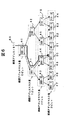
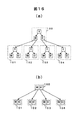
図2に示したネットワークは、パケットを送受信する端末(T11、T12、T21、T22,T31、T32、T41、T42、T51、T52)と、端末を相互に接続するサブネットワーク(SN1〜SN5)と、該サブネットワークを相互に接続するルータ(R1〜R3)から構成される。また、ルータR1はポートP11、P12、P13を持ち、ルータR2はポートP21、P22、P23、P24を持ち、ルータR3はポートP31、P32、P34、P35を持つ。各端末には識別子としてアドレスが割り当てられており、例えばIPネットワーク上の各端末には32ビットのIPアドレスが割り当てられている。このIPアドレスについて図3(a)を用いて説明する。図3(a)に示したIPアドレス(1)は、サブネットワークアドレス(2)とホストアドレス(3)から構成される。
【0043】
サブネットワークアドレスは、サブネットワークの識別子であり、ホストアドレスはサブネットワーク内の端末の識別子である。サブネットワークアドレスのビット数はサブネットマスク長で示されており、このサブネットマスク長だけ上位ビットから有効なマスク(サブネットマスク)とIPアドレスのビットごとの論理積をとることにより、IPアドレスからサブネットワークアドレスを得ることができる。
【0044】
次に、ある端末から特定の一つの端末にパケットを送信するユニキャスト通信について、図2を用いてパケット中継動作を説明する。一例として、端末T11から端末T22へユニキャストパケットを送信する場合について説明する。送信されるパケットのヘッダフォーマットを図3(c)に示す。図3(c)の送信元IPアドレスフィールド(7)には送信元端末T11のIPアドレスが格納され、宛先IPアドレスフィールド(8)には宛先端末T22のIPアドレスが格納される。端末T11からのユニキャストパケットを受信したルータR1は、パケットヘッダ内の宛先IPアドレスフィールドを検査し、宛先端末T22がサブネットワークSN2上にあり、かつ、サブネットワークSN2がルータR2経由で接続されていることを認識し、パケットを送信すべきルータR2のIPアドレス(ネクストホップIPアドレスと呼ぶ)および送信すべきポートP12を決定し、パケットを出力する。ルータR1からのユニキャストパケットを受信したルータR2は、パケットヘッダ内の宛先IPアドレスフィールドを検査し、宛先端末T22がサブネットワークSN2上にあり、かつ、サブネットワークSN2がルータR2に直接接続されていることを認識し、ネクストホップIPアドレス(今の場合、端末22のIPアドレス)および送信すべきポートP22を決定し、パケットを出力する。
【0045】
次に、ルータの構成およびルータのユニキャストパケットの中継動作を図4を用いて説明する。図4のルータ10は、入力ポート11-i(=1〜N)、出力ポート12-i(=1〜N)、ルーティング処理部13-i(=1〜N)、スイッチ14、通信制御部15-i(=1〜N)、管理部16から構成される。上記で説明したユニキャストパケットが入力ポート11-iから入力されると、ルーティング処理部13-iがパケットのヘッダ内の宛先IPアドレスをキーにしてユニキャストルーティングテーブルを検索する。この検索により、ネクストホップIPアドレスと、出力すべき出力ポート12-iの番号(送信ポート番号)を決定し、上記ネクストホップIPアドレスと送信ポート番号をパケットに付加してスイッチ14に送出する。スイッチ14は上記送信ポート番号に対応する出力ポート12-iを保持する通信制御部15-iにパケットをスイッチングする。スイッチングされたパケットを受信した通信制御部15-iは、パケットに付加されているネクストホップIPアドレスに対応するデータリンク層のMAC(Media Access Control)アドレスを対応テーブルに従って決定してパケットの宛先MACアドレスとして付加して、送信ポート番号に対応する出力ポート12-iにパケットを送出する。
【0046】
なお、上記のユニキャストルーティングテーブルは、管理部16が他のルータと接続情報をやり取りして作成し、各ルーティング処理部13-iに配布する。また、管理部16は、他のルータおよび端末とデータリンク層の情報のやり取りをし、ネクストホップIPアドレスと、そのIPアドレスを持つルータおよび端末のMACアドレスの対応テーブルを作成して各通信制御部15-iに配布する。
【0047】
次に、ある端末から特定の複数の端末にパケットを送信するマルチキャスト通信について、図2を用いてパケット中継動作を説明する。一例として、端末T11からある特定のマルチキャストグループに属する端末(T21、T31、T32、T41、T42、T51)へマルチキャストパケットを送信する場合について説明する。マルチキャストグループは、クラスDのIPアドレス(マルチキャスト・グループアドレス)によって識別される。このクラスDのIPアドレスの構造を図3(b)に示す。クラスDのIPアドレス(4)は、クラスDであることを示す"1110"という上位4ビット(5)と28ビットのマルチキャスト・グループID(以下、GID)(6)から構成される。上記のマルチキャスト・グループアドレスによって識別されるマルチキャストグループは、複数のサブネットワークにまたがることが可能である。また、グループに属する端末のメンバー構成は動的で、端末は自由にマルチキャストグループに参加、離脱することができる。
【0048】
端末T11から、あるマルチキャストグループ宛に送信されたマルチキャストパケットのヘッダ内の送信元IPアドレスフィールド(図3(c)の7)には送信元端末T11のIPアドレスが格納され、宛先IPアドレスフィールド(図3(c)の8)には、ユニキャストパケットの場合とは異なり、宛先のマルチキャスト・グループアドレスが格納される。端末T11からのマルチキャストパケットを受信したルータR1は、ユニキャストパケットの場合とは異なり、パケットヘッダ内の送信元IPアドレスフィールドと宛先IPアドレスフィールドの2つのフィールドを検査し、このマルチキャストパケットの送信元端末T11がサブネットワークSN1上にあることを認識し、さらに、このサブネットワークSN1から、宛先マルチキャストアドレスに属する端末の全てにパケットを送信するためにルータR1がパケットを送信すべき送信ポートP12、P13を決定し、上記ポートにパケットをコピーして出力する。ルータR1からのマルチキャストパケットを受信したルータR2は、R1と同様な検査を行い、このマルチキャストパケットの送信元端末T11がサブネットワークSN1上にあることを認識し、さらに、宛先マルチキャストアドレスに属する端末が存在するサブネットワークSN2、SN3にパケットを送信するためにルータR2がパケットを送信すべき送信ポートP22、P23を決定し、上記ポートにパケットをコピーして出力する。ルータR3も同様にしてR1から受信したパケットを送信すべきポートP34、P35を決定し、上記ポートにパケットをコピーして出力する。
【0049】
次に、ルータのマルチキャストパケットの中継動作を図4を用いて説明する。上記で説明したマルチキャストパケットが入力ポート11-iから入力されると、ルーティング処理部13-iがパケットのヘッダ内の送信元IPアドレスと宛先IPアドレス(宛先マルチキャストアドレス)をキーにしてマルチキャストルーティングテーブルを検索する。この検索により、出力すべき1つまたは複数の出力ポート12-iの番号(送信ポート番号)を決定し、受信したパケットをコピーし、各送信ポート番号をパケットに付加してスイッチ14に送出する。スイッチ14は上記送信ポート番号に対応する出力ポート12-iを保持する通信制御部15-iにパケットをスイッチングする。スイッチングされたパケットを受信した通信制御部15-iは、ユニキャストパケットの場合とは異なり、マルチキャストパケットのヘッダ内の宛先マルチキャストアドレスを用いてデータリンク層のマルチキャスト用MACアドレスを生成し、パケットの宛先MACアドレスとして付加して、送信ポート番号に対応する出力ポート12-iにパケットを送出する。
【0050】
なお、上記のマルチキャストルーティングテーブルは、ユニキャストルーティングテーブルと同様にして管理部16が他のルータと接続情報をやり取りして作成し、各ルーティング処理部13-iに配布する。
【0051】
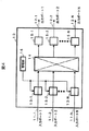
次に、本発明の一実施例として、ルータの全体構成例を図1を用いて説明する。
【0052】
まず、ルータ700の構成を図1を用いて説明する。505はスイッチであり、図4のスイッチ14に対応する。上記スイッチ505に、装置全体の管理機能と経路情報の収集・分配等の機能をもつ管理部601が接続されている。管理部601は図4の管理部16に対応する。また、スイッチ505には、高速にパケット中継処理を行う機能を有するパケット処理部600を複数接続することができる。パケット処理部600は、図4のルーティング処理部13−iに対応する。管理部601は、それぞれのパケット処理部600にルーティングテーブルを配布し、それぞれのパケット処理部600が上記ルーティングテーブルに基づいてパケット中継処理を行うことによりルータの機能を実現する。
【0053】
さらに、各パケット処理部600には、ネットワークを接続するための通信ポートを備える通信制御部501、602、603(図4の通信制御部15-iに対応)が接続される。通信制御部は、各種類のネットワークに接続することができる。また、そのネットワークの通信速度に応じて、高速通信(例えば、図2の500)ならば1ポート、低速通信(例えば、図2の604、605)ならば複数ポートを設け、1つまたは複数のネットワークと接続することができる。
【0054】
次に、上記のパケット処理部600の構成について、図1を用いて説明する。図1において、パケット処理部600は、パケット転送処理を行う転送処理部504と、パケットを格納するパケットバッファを備えるメモリ503と、メモリ503に格納されたパケットのヘッダ情報を用いて経路検索を行う経路検索処理部400と、転送処理部504および通信制御部501を制御する制御回路502とを有する。経路検索処理部400は、ルーティングテーブルを格納するメモリ300と、そのルーティングテーブルを検索し、検索結果を転送処理部504へ出力する経路検索処理回路200から構成される。
【0055】
次に、パケット処理部600における、マルチキャストパケットの中継処理の動作を説明する。なお、パケット中継処理を行う前に、管理部601が、スイッチ505に接続している全パケット処理部600に、それぞれのマルチキャストルーティングテーブルを配布しており、各パケット処理部600はメモリ300にルーティングテーブルを格納している状態とする。通信制御部501がネットワーク500から受信したマルチキャストパケットをメモリ503へ転送し格納する。転送処理部504はメモリ503に格納されたパケットデータの内、パケットヘッダ情報を抽出して経路検索処理部400へ転送する。経路検索処理回路200は、受信パケットのヘッダ内の送信元アドレスと宛先マルチキャスト・グループアドレスを用いてメモリ300内に格納されているマルチキャストルーティングテーブルの検索を行い、検索結果として、パケットを送信すべきN個(Nは1以上の整数)の送信ポート番号を転送処理部504へ転送する。
【0056】
上記の検索結果を受信した転送処理部504は、先にメモリ503に格納されているパケットに対してパケットヘッダの書換などの処理を施し、パケットに上記N個の送信ポートの内の1つの番号を付加してスイッチ505に転送する。転送処理部504は上記の処理をN回繰り返し、1つの受信パケットに対する転送処理を終了する。また、送信ポート番号が自パケット処理部に接続されている通信制御部のポート番号である場合は、自パケット処理部に接続されている通信制御部にパケットを送信する。
【0057】
スイッチ505は転送処理部504により転送されたパケットを、付加されている送信ポート番号に従い、各パケット処理部にスイッチングする。上記スイッチングされたパケットを受信したパケット処理部600は、上記パケットを通信制御部(501、602、603)へ転送する。通信制御部は、上記パケットのヘッダ内の宛先マルチキャストアドレスからマルチキャスト用MACアドレスを生成し、宛先MACアドレスとしてパケットに付加して各ネットワークに送信する。
【0058】
本発明は、上記の経路検索処理部400の高速化に関するものである。以下では、この経路検索処理部400に関し、まず、方式1として、マルチキャストルーティングテーブルを2分木に構成し、その2分木構造を検索する検索方式(以下、2分木検索方式と呼ぶ)について説明する。方式2として、方式1を改良し、さらに検索を高速に行うために、マルチキャストルーティングテーブルを2のp乗分木に構成し、その2のp乗分木構造を検索する検索方式(以下、2のp乗分木検索方式と呼ぶ)について説明する。また、その方式2の説明の中で、マスク長mビットのノードをメモリ上に展開して方式1、2のノードを渡る回数を削減する方式(方式3)について説明する。最後に、本発明の一実施例として、方式2および3の方式を適用した経路検索処理を実現するハードウェア構成について説明する。
【0059】
まず、方式1の2分木検索方式について説明する。
【0060】
従来の技術で説明したように、マルチキャスト経路検索を行う際、受信パケットのヘッダ内の送信元IPアドレスと、宛先マルチキャスト・グループアドレスを検索のキーとしてマルチキャストルーティングテーブルを検索する。すなわち、この2つの情報の組み合わせにより、そのマルチキャストパケットの送信元から宛先までの経路が識別される。
【0061】
従って、送信元IPアドレスとマルチキャスト・グループアドレスを連結して、これを経路アドレスとして定義し、この経路アドレスと経路情報の組をエントリとしてマルチキャストルーティングテーブルを構成することにより、この経路アドレスをキーとして、マルチキャストルーティングテーブルを検索することができる。
【0062】
また、上記の2つのアドレスのうち、マルチキャスト・グループアドレスに関しては、マルチキャスト・グループ一つに対して一つのアドレスが割り当てられているので、ルーティングテーブル検索時は、エントリに保持されたマルチキャスト・グループアドレスとの一致比較を行えばよい。
【0063】
しかし、上記の2つのアドレスのうち、送信元IPアドレスに関しては、受信パケットの送信元IPアドレスに、エントリに保持されているサブネットマスク長だけ上位ビットから有効なマスクをかけたものとエントリに保持されている送信元サブネットワークアドレスに一致するエントリの経路情報を検索結果とするが、この場合、ユニキャスト経路検索と同様に最長一致検索を行う必要がある。
【0064】
以上のことから、送信元IPアドレスとマルチキャスト・グループアドレスの連結順を、マルチキャスト・グループアドレス、送信元IPアドレスの順にして、これを経路アドレスとして定義し、この経路アドレスのビットパターンに従ってマルチキャストルーティングテーブルを2分木構造に構成することにより、従来技術3に述べられているRadish方式を用いたユニキャスト経路検索方式と同様にして、経路アドレスに関して最長一致検索を行うことができる。この場合、経路アドレスの定義から、マルチキャスト・グループアドレスについては一致比較、送信元IPアドレスに関しては最長一致検索を行うことできる。
【0065】
図5に2分木で構成されたマルチキャストルーティングテーブルを検索する際に用いる経路アドレスを示す。なお、この経路アドレスは後述する2のp乗分木検索方式にも採用する。図5(a)の経路アドレス32は、マルチキャスト・グループアドレス(30)と送信元IPアドレス(31)とを連結したものであり、ビット数は64ビットである。図5(b)の経路アドレス33は、マルチキャスト・グループアドレス(30)から"1110"というIPアドレスのクラスDを示す上位4ビットの値を除いたマルチキャスト・グループID(34)と、送信元IPアドレス(31)とを連結したものであり、ビット数は60ビットである。木構造を構成するための値(今の場合は検索アドレス)のビット数が少ない方が木の構造が浅くなり、検索時に辿る最大ノード数が減るため、以下では、ビット数の少ない図5(b)の経路アドレス33を採用して説明する。
【0066】
次に、上記の経路アドレスを用いてマルチキャストルーティングテーブルを2分木に構成する方法について説明する。木構造の考え方は経路アドレスのビット数には依存しないので、簡単のため、マルチキャスト・グループIDは1ビット、送信元IPアドレスは2ビットと仮定して説明する。この場合経路アドレスは3ビットとなる。
【0067】
図6に2分木の構造の例を示す。図6に示すように、各ノードは、経路アドレスモaaaモと、経路アドレスマスク長n、および、そのノードの下につく二つのノードへのポインタを持つ。ここで、経路アドレスマスク長とは、そのノードが持つ経路アドレスの上位何ビットが有効であるかを示す値であり、また、そのノードでの受信パケットの経路アドレスの検査ビット位置も示す。また、経路アドレスと経路アドレスマスクの組を表記法モaaa:nモで表す。この表記法により、マスク付き経路アドレスを表すことにする。
【0068】
各ノードを木の上から順に、経路アドレスマスク長0ビット、1ビット、2ビット、3ビットのノードと呼ぶ。
【0069】
経路アドレスマスク長0ビットのノード(40)では、経路アドレスマスク長の値で示されている経路アドレスの第0ビットを検査し、その値が0か1かに従い左/右のポインタを辿ることにより経路アドレスマスク長1ビットのノード(41、42)に移り、経路アドレスマスク長1ビットのノードでは、経路アドレスの第1ビットが0か1かに従い左/右のポインタを辿ることにより経路アドレスマスク長2ビットのノード(43、44、45、46)に移り、経路アドレスマスク長2ビットのノードでは、経路アドレスの第2ビットが0か1かに従い左/右のポインタを辿ることにより経路アドレスマスク長3ビットのノード(47、48、49、50、51、52、53、54)に移る。
【0070】
検索したい経路アドレスについて、この木の経路アドレスマスク長0ビットのノード(40)から順に、各ビットが0か1かに従いポインタを辿った場合、経路アドレスマスク長0ビットのノードは経路アドレスがどの値をとる場合にも通過し、経路アドレスマスク長1ビットのノード(41、42)は左から順に経路アドレスの各ビットが0xx、1xxの場合に通過し、経路アドレスマスク長2ビットのノード(43、44、45、46)は左から順に経路アドレスの各ビットが00x、01x、10x、11xの場合に通過し、経路アドレスマスク長3ビットのノード(47、48、49、50、51、52、53、54)は左から順に経路アドレスの各ビットが000、001、010、011、100、101、110、111の場合に通過する。ここで、xは、そのビット値が0または1のどちらでも良いことを示す。
【0071】
従って、経路アドレスマスク長0ビットのノード(40)は、経路アドレスがマスク付き経路アドレス 000:0に属する場合に通過し、経路アドレスマスク長1ビットのノード(41、42)は、経路アドレスがそれぞれマスク付き経路アドレス000:1、100:1に属する場合に通過し、経路アドレスマスク長2ビットのノード(43、44、45、46)は、経路アドレスがそれぞれマスク付き経路アドレス000:2、010:2、 100:2、110:2に属する場合に通過し、経路アドレスマスク長3ビットのノード(47、48、49、50、51、52、53、54)は、経路アドレスがそれぞれマスク付き経路アドレス000:3、001:3、...、111:3に属する場合に通過する。
【0072】
上記の通り、この木の各ノードは、経路アドレスと経路アドレスマスク長が異なる全マスク付き経路アドレスに1対1に対応している。
【0073】
上記の2分木において、図7に示すマルチキャストルーティングテーブルの各エントリに対応するノード40、48、44、42、53に該エントリを割り付ける。具体的には、図12を用いて後述するように、ノードのデータ構造内にエントリが割り付けられているか否かを示すフラグを設け、エントリが割り付けられたノード内の上記フラグの値を1に設定し、かつ送信ポート情報あるいは送信ポート情報へのポインタをノード内に格納する。本明細書では、ノードに*を付記することにより、ノードにエントリが割り付けられていることを表すことにする。
【0074】
受信パケットの経路アドレスが011(図6の60)の場合、この木の上から各ビットが0か1かに従いポインタを辿ると、"*"が付記されたノード40、44が、マスク付きの検索で一致することが分かる。そこで、ルーティングテーブルエントリが複数一致した場合は、送信元IPアドレスに関して最長一致検索を行うことを考慮すると、一致した"*"付きノード40、44の内、上記で定義した経路アドレスマスク長が最も長いノード、すなわち最も末端に近いノード44に割り付けられたエントリの経路情報を、ルーティングテーブルの検索結果とする。なお、図7のルーティングテーブルの例では、エントリ内の経路情報は省略している。
【0075】
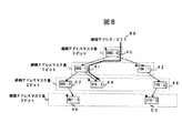
上記検索方法から分かるように、"*"が付記されておらず、かつ"*"付きのノードにたどり着くための途中経路にもなっていないノード47、49、50、51、52、54、45は木から取り除いても、検索結果には影響しない。むしろ、最下のノードが、"*"が付記されていていないノードの場合は最下まで移動せずに検索が終了するために効率的である。そこで、"*"が付記されておらず、かつ"*"付きのノードにたどり着くための途中経路にもなっていないノードを木から取り除くと図8のようになる。
【0076】
上記の方法を用い、経路アドレス長が32ビットと仮定した場合、図9に示す経路テーブルに対応する2分木を構成すると、図10に示す分岐も"*"も無いノードの長い列61ができる。なお、図9のルーティングテーブルの例では、図7と同様にエントリ内の経路情報は省略している。また、図10の0xNNNNNNNNという表記法は、NNNNNNNNが16進数表示であることを示す。このように、左右の片方のポインタだけに次のノードがつながり、かつエントリが割り当てられていないノードを取り除くことにより、検索時に辿るノード数を減らすことができる。
【0077】
図10の例においては、分岐も"*"も無いノード列61を取り除き、直ぐ上のノード62の分岐方向(図10では右側)に、取り除かれたノード列61の直ぐ下のノード63を付ける。その結果、図11に示す形となる。このように途中のノード列を取り除くことを、以後、木の縮退と呼ぶ。
【0078】
次に縮退した2分木の検索法を説明する。
【0079】
図11に示す例では、経路アドレスマスク長0ビットのノード62で第0ビットの検査を行った後、経路アドレスマスク長15ビットのノード63に跳ぶので、経路アドレスマスク長15ビットのノード63で第15ビットだけを検査したのでは、途中のビット、即ち第1ビットから第14ビットが検査できない。そこで、第1ビットから第15ビットの検査を一回の処理で行う為に、受信パケットの経路アドレスの第1ビットから第15ビットとノード63の経路アドレス0x85040000の第1ビットから第15ビットの一致比較を行う。比較結果が一致すれば正しいノードにたどり着いたこと、即ち、縮退しない木で1ビットづつ比較しても、このノードにたどり着いたことを意味し、一致しなければ、正しくないノードにたどり着いたこと、即ち縮退しない木では、行き先が無いことを意味する。
【0080】
ここで、図11に示す例では、第0ビットは、既にテストされ、第0ビットが等しくなる方の分岐が選択されている為、常に一致する。一般に、あるノードにたどり着く毎に、正しいノードにたどり着いたか否かを検査していれば、第0ビットから、そのノードの経路アドレスマスク長までのビットに関しては、受信パケットの経路アドレスと、ノードの経路アドレスとが等しいことが保証されているので、次のノードにたどり着いたときに、前にどのビットまで検査したかに関らず、第0ビットからノードの経路アドレスマスク長までのビットに関して、受信パケットの経路アドレスとノードの経路アドレスとが等しいか否かを調べて良い。
【0081】
次に、上記で説明した2分木を構成するノードのデータ構造について、図12を用いて説明する。図12(a)において、ワード110、111内の次のノードのマスク長0、1は、このノード自身の経路アドレスマスク長ではなく、このノードの直下のノードの経路アドレスマスク長である。このように、自分自身でなく直下のノードのマスク長を設定する理由は高速化のためであり、その説明は図20を用いて後述する。ワード110、111内のフラグ0、フラグ1は、このノードがエントリが割り付けられているノードか否か、即ち、図6、8、10、11で示した木の例において、このノードが、"*"が付記されているノードか否かを示すフラグ(以下、エントリ有りフラグと呼ぶ)や、このノードに一致するパケットに関する属性フラグなどが設定されるフィールドである。フラグ0とフラグ1には、同じ値を設定する。これは、ワード110とワード111の一つだけを読めば良いようにするためであり、このように、ノードの全てを読むのではなく、一部分を読むことによる高速化については図20を用いて後述する。ワード110、111内の次のノードへのポインタ0、1は、経路アドレスの、このノードの経路アドレスマスク長で示されるビット位置の値が、それぞれ0、1のときに次に辿るノードへのポインタである。ワード112、113の経路アドレスは、このノードに対応する経路アドレスであり、例えばワード112にはノードの経路アドレスの内、上位28ビットを設定し、ワード113にはノードの経路アドレスの内、下位32ビットを設定する。
【0082】
図12(a)では、2分木ノードのデータ構造の中に送信ポート情報114を保持する例を示している。図12(b)では、送信ポート情報114を2分木ノード構造から分離し、分離した送信ポート情報へのポインタ115を保持する例を示している。送信ポート情報は、受信マルチキャストパケットを転送すべき1つまたは複数の送信ポート番号を示し、ルータのポート数が多い場合は数ワード必要になる。従って、図12(a)のように、2分木ノード構造内に送信ポート情報114を保持する場合、エントリが割り付けられている2分木ノードと、エントリが割り付けられていない2分木ノードで、その大きさが大きく異なることになる。このようにノードの大きさが異なると、ノード内の次ノードへのポインタに必要なビット数が多くなることや、そのポインタから実際のメモリのアドレスを計算する処理が複雑になり、特にハードウェア構成が複雑になるという問題が考えられる。
【0083】
図12(b)のように送信ポート情報をノードから分離し、ノードにはその送信ポート情報へのポインタ115を保持する場合、エントリが割り付けられている/いないに関わらずノードの大きさは一定になり、ハードウェア構成を単純にする利点がある。
【0084】
次に、方式2の2のp乗分木検索方式について説明する。
【0085】
上記で説明した2分木方式では、一つのノードに2つの分岐先があり1ビットづつ検索していた。検索のキーのビット数は、検索時に辿るノードの数(の最大値)に一致する。したがって、最大の検索時間は(式1)で表される。
【0086】
(最大検索時間)=(一つのノードの処理時間)×(検索のキーのビット数) ・・・ (式1)
すなわち、最大検索時間は検索のキーのビット数に比例する。この最大検索時間をさらに大幅に短縮し、高速化することが求められる。
【0087】
そこで、以下で説明する2のp乗分木方式では、一つのノードに2のp乗の分岐先を設け、同時にpビットづつ検索することにより、従来に比べ、検索時間を1/pに短縮するものである。以後、一つのノードに2のp乗の分岐先があるノードのことを2のp乗分木ノードと呼ぶ。
【0088】
2のp乗分木ノードは、2分木方式で説明した2分木ノードから構成される木を変形することにより作成する。木の変形の方法は、経路アドレスマスク長nの2分木ノード一つと、この2分木ノードの下に存在する、経路アドレスマスク長(n+1)ビットから(n+p−1)ビットの2分木ノードを、一つの2のp乗分木ノードに対応させるものである。また、以下では、上記のように対応させてまとめた2のp乗分木ノードに関し、まとめる前に頂点にあった2分木ノードのマスク長nを引き継いで、この2のp乗分木ノードのマスク長をnと定義する。
【0089】
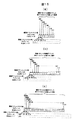
上記の変形法の例として、2分木から8分木への変形法を図13に示す。
【0090】
経路アドレスのビット数が60ビットの場合で、8分木を構成する場合を考える。この場合、一つの8分木に対応させる2分木ノードの選び方として、マスク長0〜2、3〜5、....、57〜59、60ビットの2分木ノードを、それぞれ一つの8分木ノードとする場合(図13(a))と、マスク長1〜3、4〜6、....、55〜57、58〜60ビットの2分木ノードを、それぞれ一つの8分木ノードとする場合(図13(b))と、第2〜4、5〜7、....、56〜58、59〜60ビットの2分木ノードを、それぞれ一つの8分木ノードとする場合(図13(c))の3通りがあり、どの区切り方でも、構成可能だが、木全体では、エントリの追加、削除を容易に行えるように、上記3通りのビット位置の区切り方の内、一つを使用する。
【0091】
上記3通りのビット位置の区切り方の内、最初の区切り方以外では、マスク長が0ビットから始まっていないので最初のビットの検査を別に行う必要がある。この検査には、マスク長mビットのノードをメモリ上の決まった位置に展開する方法(以下、方式3と呼ぶ)を使用する。
【0092】
以下、方式3について説明する。方式3は、2のp乗分木構造のマスク長mビットのノードを、ノードがある場合も無い場合も区別せず全て予め用意し、メモリ上の決まった位置に展開しておき、経路検索開始時に、受信パケットの経路アドレスの上位mビットの値に従って上記の展開されたノードの内の一つを選択してメモリから読み込む。この方式により上位mビット分の検索時間を省くことができる。
【0093】
上記の方式3を適用した例を、図13(b)、(c)に示した区切り位置の場合について図14(a)、(b)に示す。
【0094】
図14(a)に示す構成では、マスク長1ビットの8分木ノード90、91をメモリ上の決まった位置に並べ、それぞれを、受信パケットの経路アドレスの第0ビットが0か1かに従い選択することにより、最初の第0ビットの検査を行ったことになる。図14(b)に示す構成では、マスク長2ビットの8分木ノード92、93、94、95をメモリ上の決まった位置に並べ、それぞれを、受信パケットの経路アドレスの第0〜1ビットの値が00か01か10か11かに従い選択することにより、最初の第0、1ビットの検査を行ったことになる。
【0095】
さらに、図13(a)、(b)、(c)に示す各ビットの区切り位置の場合に、それぞれ最初に並べる8分木ノード数を1、2、4個ではなく、これらの8倍である8、16、32個、8の2乗倍である64、128、256個、或いは一般に8のq乗倍個にし、最初の1回、2回、或いは一般にq回の8分木ノードの検索時間を無くすことも可能である。この場合、メモリ上の決まった位置に展開する8分木ノードのマスク長mは、図13(a)、(b)、(c)に示す各ビットの区切り位置の場合、それぞれ、m=3×q、1+3×q、2+3×qとなり、この上位mビット分の検索時間を省くことができる。q=1の場合、即ち8分木ノードの1回のノードの検索時間を無くす場合で、図13(a)、(b)、(c)に示す3通りの各ビットの区切り位置の場合についてのメモリ上へのノードの展開法を、図15(a)、(b)、(c)にそれぞれ示す。
【0096】
図15(a)では、マスク長m=3の8分木ノードを8個メモリ上の決まった位置に展開し、受信パケットの経路アドレスの第0〜2ビットの計3ビットの値に従って、展開された8分木ノードの内の一つを選択する。図15(b)では、マスク長m=1+3=4の8分木ノードを16個メモリ上の決まった位置に展開し、受信パケットの経路アドレスの第0〜3ビットの計4ビットの値に従って、展開された8分木ノードの内の一つを選択する。図15(c)では、マスク長m=2+3=5の8分木ノードを32個メモリ上の決まった位置に展開し、受信パケットの経路アドレスの第0〜4ビットの計5ビットの値に従って、展開された8分木ノードの内の一つを選択する。
【0097】
以上、8分木を例にして方式3について説明したが、同様にして、マスク長mビットの2のp乗分木ノードをメモリ上の決まった位置に展開し、上位mビット分の検索時間を省くことができる。p、qの値を大きくすると、経路検索時間を短縮することができるが、多くのメモリを必要とするので、p、qの値は、メモリ効率と性能のトレードオフから決めるようにする。
【0098】
以上、方式3について、2のp乗分木ノードの場合について述べたが、同様にして、方式1の2分木検索方式にこの方式3を適用することも可能である。
【0099】
次に、4分木ノード、8分木ノード、16分木ノード、或いは一般に2のべき乗分木のノードの構成法を図16を用いて説明する。
【0100】
図16は4分木で、ある1つの2分木ノードA、B、C、D、Eと、その直下の2個の2分木ノードA0、A1、B0、B1、C0、C1、D0、D1、E0、E1の、各々合計3個の2分木ノードをまとめて一つの4分木ノード100、101、102、103、104にする場合の例であり、合計3個の2分木ノードをつぶして、下の方の2分木ノードだけの大きさにする。つぶし方は、経路アドレスマスク長に関する最長一致検索の仕様に従い、経路検索を行った場合に、2分木の場合と4分木の場合とで、経路検索結果が同じになる、という条件を満たすように行う。
【0101】
4分木の場合の、このノードのつぶし方を図17に示す。図17において、*Aという表記は、ノードAに割り付けられているエントリ内の経路情報を表すことにする。また、*Aという表記がないノードにはエントリが割り付けられていないことを意味する。
【0102】
2分木構造において、3つのノードが全部ある場合(図17(a))、全ノードにエントリが割り付けられていたら、下のノードの経路情報*A0、*A1を残し、上のノードは削除する。これは、ノードAのエントリが一致したらノードA0かノードA1のどちらかのエントリが必ず一致するので、最長一致検索を行うことから、ノードAの経路情報*Aが使用されることが無いからである。
【0103】
上のノードAにエントリが割り付けられており、下のノードA0、A1の内A1にだけエントリが割り付けられていない場合(図17(b))、ノードA1に、Aの経路情報*Aを格納する。下のノードA0、A1の内A0だけエントリが割り付けられていない場合も同様である。
【0104】
下のノードA0、A1の両方にエントリが割り付けられていない場合(図17(c))には、A0、A1の両方のノード内に、Aの経路情報*Aを格納する。
【0105】
下のノードA1が無い場合(図17(d))、A1を補い、A1には、上のノードAの経路情報*Aを格納し、さらに、ノードA1の下にはノードが繋がっていないので、ノードA1の下のノードへのポインタはNULLにする。下のノードA0、A1の内A0だけエントリが割り付けられていない場合も同様である。
【0106】
下のノードA0、A1の両方が無い場合(図17(e))、両方を補い、両方のノードに、Aの経路情報*Aを格納し、両方のノードの下のノードへのポインタはNULLにする。
【0107】
上のノードAにエントリが割り付けられていない場合(図17(f))、ノードAをただ単に削除する。
【0108】
上のノードAに経路が割り付けられておらず、下のノードA0、A1の内、A1にもエントリが割り付けられていない場合(図17(g))、4分木にした場合もA1の経路情報は無い。下のノードA0、A1の内、A0にエントリが割り付けられていない場合も同様である。
【0109】
上のノードAにエントリが割り付けられてなく、下のノードA0、A1の両方にエントリが割り付けられていない場合(図17(h))、4分木にした場合もA0、A1の両方のノードの経路情報は無い。
【0110】
下のノードA0だけしかない場合(図17(I))には、下のノードA1を補う。下のノードA1だけしかない場合も同様である。
【0111】
8分木の場合も同様にして、一つにまとめる7個の2分木ノードをつぶして、一番下の4個のノードだけの大きさにする。上の方の3つの2分木ノードのつぶし方の2つの例を図18に示す。
【0112】
図18(a)は一つにまとめる7個の2分木ノードが全てあるが、その内のいくつかにしかエントリが割り付けられていない場合の例であり、最下の4つのノードの内、エントリが割り付けられていないノードA01、A10には、そのノードの上方につながっているノードの内、エントリが割り付けられている最も下、即ち最も経路アドレスマスク長が長いノード(それぞれ、A、A1)の経路情報*A、*A1を格納する。
【0113】
図18(b)は一つにまとめる7個の2分木ノードの内のいくつかしかノードが存在しない場合の例であり、存在しないノードA01、A10を、まずエントリが割り付けられていないノードとして補い、図18(a)と同じ規則で、経路情報を格納する。最下の4つのノードA00、A01、A10、A11の内、補ったノードA01、A10の下には、ノードが繋がっていないので、下のノードへのポインタはNULLにする。
【0114】
一般に2のp乗分木の場合も同様にして、一つにまとめる(2のp乗−1)個の2分木ノードをつぶして、一番下の2の(p−1)乗個のノードだけの大きさにする。
【0115】
また、4、8、16、...分木ノードでは、2分木ノードを2、4、8、...個まとめて扱うので、1つの4、8、16、...分木ノードにまとめられる2分木ノード間で共通な要素は、一つだけ持てばよく、これにより、4、8、16、...分木ノードのメモリ量を小さくできる。1つにの4、8、16、...分木ノードにまとめられる2分木ノード間で共通な要素には、ノードが持つ経路アドレス、及び、経路アドレスマスク長があるが、経路アドレスマスク長については、後述するように、このノード自身の経路アドレスマスク長ではなく、このノードの直下のノードの経路アドレスマスク長を持つようにするので、メモリ量を小さくする効果は無い。
【0116】
次に、2のp乗分木ノードの一つの例として、4分木ノードのデータ構造について図19を用いて説明する。4分木ノードを構成する際、上記2分木ノードを2つまとめ、まとめられる2つの2分木ノードに共通のデータを一つだけ保持するようにする。この共通のデータは、そのノードの経路アドレスだけである(ワード124、125)。また、まとめられる2分木ノードが、経路が割り付けられているか否かによりその大きさが異なると、それらをまとめて構成する4分木ノードの大きさも異なってしまう。従って、図12(b)で示したように、送信ポート情報をノードから分離し、ノード内にはこの送信ポート情報へのポインタを保持する2分木ノードをまとめる。
【0117】
図19において、ワード120、121、122、123内の次ノードのマスク長tt、フラグtt、次ノードへのポインタttはそれぞれ、受信パケットの経路アドレスの、このノードの経路アドレスマスク長mで示された第mビット、および第m+1ビットの値ttに対応する値である。ここでttは00、01、10、11の値を取りうる。2分木の場合と同様に、フラグ00とフラグ01は同じ値を設定し、フラグ10とフラグ11も同じ値を設定する。
【0118】
図12(b)に示す例では、2分木ノードは、2のべき乗の大きさである16バイトにわずかに入りきらない大きさになっているが、4分木ノードにし、1ノード内に経路アドレスを一つしか持たないようにすることで、2のべき乗の大きさである32バイトに丁度収まるようになっている。8分木ノードにし、経路アドレスを1ノードで一つだけ保持するようにすれば、64バイトの大きさに収まる上に、4バイトの余裕ができ、この領域は他の情報を入れるのに使用できる。さらに1つにまとめる2分木の数を増やせば(すなわち、2のp乗分木のpの値を大きくとれば)、2のべき乗の大きさに対し、1つのノードの大きさをさらに小さくできる。
【0119】
このように、1ノードの大きさを2のべき乗の大きさに収めることで、ハードウェアの構成を非常に簡単にできる。ハードウェアの構成を簡単にできる例を以下に示す。
【0120】
1つ目の例として、4分木ノードが32バイトに収まる場合、メモリを複数バンクで構成していた場合でも1ノードのメモリ領域がバンク境界にまたがることがないこと、メモリにダイナミックRAMを使用していた場合でも1ノードのメモリ領域がRowアドレス境界にまたがることがないこと。
【0121】
2つ目の例として、ノード内の各要素のメモリ上のアドレス(以下、メモリアドレスと呼ぶ)を求めるときに、そのノードへのポインタとそのポインタからのオフセットの足し算でなく、メモリアドレスの上位ビットはポインタの値にし、下位ビットをオフセットにすればよいこと。例えば4分木ノードが32バイトに収まる場合、あるノード内のある要素のメモリアドレスを生成するには、そのノードへのポインタをメモリアドレスの2の5乗ビット以上に割り付け、ノード内のその要素へのオフセットをメモリアドレスの2の0乗ビットから2の4乗ビットに割り付ければよい。
【0122】
3つ目の例として、例えば4分木ノードが32バイトに収まる場合、各ノードに保持する次のノードへのポインタとして、(次のノードの先頭のバイトアドレス)÷32、という値を保持すればよく、1ノード内で1ポインタあたり5ビットづつデータ量を減らせることが挙げられる。
【0123】
次に、例えば、図1の経路検索処理回路200を専用LSIで構成する場合のノードの読み込み方式について説明する。4、8、16、...分木ノードにした場合に1つのノードが大きくなり、検索処理時にテーブルを保持するメモリから専用LSI内に1つのノードを全て読み込むと、ノードを大きくするに従い読み込み時間が伸び、性能低下要因となる、という問題があるが、この問題は、ノードを大きくしたときに、1つのノード全てを読み込まず一部だけを読み込む、という方で回避する。この方法について、図20を用いて説明する。
【0124】
図20に4分木の場合の例を示す。既に図19を用いて説明したように、経路アドレスマスク長mビットの4分木ノードは、図12(b)で示した、経路アドレスの第mビット目の値が0の場合に対応する2分木ノードと、1の場合に対応する2分木ノードを併せた構造になっている。従って、受信パケットの経路アドレスの第mビット目の値にしたがって、対応する方の2分木ノードの部分だけを読み込むことにより、ノードの大きさが大きくなっても2分木ノードの場合と同じデータ量を読み込むようにする。このとき、図19で示した、1つにまとめられる2分木ノード間で一つだけ保持する要素であるノードの経路アドレス(ワード124、125)は、受信パケットの経路アドレスのmビット目の値に係わらず読み込むようにする。
【0125】
さらに、受信パケットの経路アドレスの第(m+1)ビット目の値に従い、2分木ノードで2つ存在した次ノードへのポインタの内、一方だけを読み込むようにすることにより、読み込むデータ量をさらに少なくする。
【0126】
この方法は2分木検索方式にも使用できる。例えば第mビット目の2分木ノードの場合には、受信パケットの経路アドレスの第mビット目の値に従い、2つの次ノードへのポインタの内、一方だけを読み込むようにする。
【0127】
上記方法を全て行い、結局、このノードの経路アドレスマスク長をmとした場合、宛先アドレスの第m、m+1ビットの値が00か、01か、10か、11かに従い、それぞれ(ワード120→ワード124→ワード125→ワード126)、(ワード121→ワード124→ワード125→ワード126)、(ワード122→ワード124→ワード125→ワード127)、(ワード123→ワード124→ワード125→ワード127)の順にデータを読み込むようにする(図20(b))。
【0128】
このように、あるノードの一部分だけを読み込むためには、このノードの経路アドレスマスク長mを知る必要があり、このノードの経路アドレスマスク長mは、1ノードのデータ読み込みの最初に読み込むか、この情報を1つ前のノードに移し、一つ前のノードのデータ読み込み時に読み込む必要がある。ノードのマスク長mを1ノードのデータ読み込みの最初に読み込む方法は、例えば、図1の経路検索処理回路200を専用LSIで構成する場合、宛先の第mビット目の値の抽出のための専用LSI内のゲートディレイ、及び、次に読み込む部分のメモリアドレスをメモリに出力してからメモリからのデータを専用LSI内に読み込むまでの時間であるメモリリードレイテンシだけ、マスク長mを読み込んでから次に読み込む部分を選択して読み込むまで時間が空いてしまうので、ノードの一部だけを読むことによる性能向上効果が少ない。ノードのマスク長mを1つ前のノードに移し、一つ前のノードのデータの読み込み時に読み込む方が性能向上効果がある。
【0129】
さらに、ノードの経路アドレスマスク長mを1つ前のノードに移す場合、1ノードのデータを読み込む順序を、1番目に次のノードの経路アドレスマスク長m、次のノードへのポインタ、次にノードの経路アドレス、送信ポート情報へのポインタの順にすることにより、次のノードの最初に読み込む部分のメモリアドレスが最も早く計算できるようにする。
【0130】
次のノードへのポインタは、次のノードのメモリ領域の先頭部分を指しており、次のノードの先頭から最初に読み込む部分までのメモリアドレスのオフセットは、次のノードのマスク長mを読み込み、受信パケットの経路アドレスの該当ビット位置の値を検査することにより、得られる。
【0131】
次に、1ノード内で、条件によっては、読み込む必要が無い要素を、その条件に従って読み込まないようにすることで、読み込みの時間を削減し、高速化を図る方法について図21を用いて説明する。
【0132】
図21に4分木の場合の例を示す。2分木構造の説明で述べたように一般に木構造においては、全ノードにエントリが割り付けられているわけではなく、枝の分岐の個所では、エントリが割り付けられていなくてもノードを設ける必要がある。図21に示すように、ノードデータの最初に読み込むワード120、121、122、123内のフラグ内のエントリ有りフラグの値に従い、エントリが割り付けられていないノードでは、送信ポート情報へのポインタを読み込まないようにすることで、読み込み時間の短縮を図ることができる。エントリ有りフラグは1ビットで表現できるので、この情報を読み込むことによる読み込み時間の増大は小さい。
【0133】
この方法では、このノードのマスク長をmとすると、宛先アドレスの第m、m+1ビットの値が00で、ワード120を読み、フラグ00から、4分木を構成する0番目の2分木に経路情報が無いと判った場合、ワード124、125だけを読めば良く、経路情報が有ると判った場合にだけ、図21(b)に示すようにワード124→ワード125→ワード126の順に読めば良い。宛先アドレスの第m、m+1ビットの値が01、10、11の場合も同様である。
【0134】
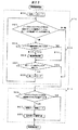
以上、2分木検索方式(方式1)、2のp乗分木検索方式(方式2)、およびマスク長mビットのノードをメモリ上に展開する方法(方式3)という各検索方式について説明した。次に、図1の経路検索処理回路200が上記の方式を用いて経路検索処理を行う際のフローチャートについて図22を用いて説明する。図22のフローチャートでは、方式2と方式3とを組み合わせた場合の例を示す。この例では、経路アドレスの第0ビットから第(m−1)ビットの値に従って、メモリ上の決まった位置に展開された2のp乗分木ノードの一つを選択する。以下ではこのように選択し、検索の最初に読込む2のp乗分木ノードを初段ノードと呼ぶ。第mビット以降は経路アドレスをpビットずつ検索し、2のp乗分木を検索する。図1のメモリ300には、上記の方式2および方式3の検索方式に従った2のp乗分木ノードデータ、および送信ポート情報が格納されているとする。
【0135】
なお、以下では方式2と方式3とを組合わせた例について説明するが、方式1と方式3とを組み合わせた場合でも同様なフローチャートに従うことで実現可能である。また、このフローチャートに従うことにより、ソフトウェアでもハードウェアでも経路検索処理を実現することができる。ソフトウェアで実現する場合、図1の経路検索処理回路200にはCPUを用いればよい。またハードウェアで実現する場合、図1の経路検索処理回路200を専用LSIで構成すればよい。
【0136】
図22の処理810は木構造検索処理であり、また、処理811は送信ポート情報処理である。まず、木構造検索処理810について説明する。
【0137】
図1の経路検索処理回路200は、受信パケットの宛先マルチキャスト・グループIDおよび送信元IPアドレスを受け取ると、これらの値から図5を用いて説明した経路アドレスを生成し、この経路アドレスと初段ノードのマスク長mの値から初段ノードへのポインタを生成し、このポインタと、経路アドレスの第mビットから第(m+p−1)ビットの値(以下、検査ビット値と呼ぶ)に従ってメモリ300に格納されている初段ノードの読み込みアドレスを生成し、メモリ300から該初段ノードの一部を読み込む(図22の800)。
【0138】
次に、図1の経路検索処理回路200は、受信パケットの経路アドレスにノードのマスク長だけ上位ビットから有効とするマスクをかけたものと、ノードの経路アドレスと比較し(図22の801)、不一致の場合は木構造検索処理810を終了する(図22の809)。一致する場合は図22の処理802に進む。
【0139】
次に、図22の処理802、および803について説明する。これらの処理は、最長一致検索を実現するための経路情報の更新処理である。経路情報としては、図1のメモリ300が出力するノードデータの内、エントリ有りフラグと、送信ポート情報へのポインタがある。図1の経路検索処理回路200は、ノードデータ内のエントリ有りフラグを検査し、エントリ有りフラグの値が1の場合(図22の812)のみ、読み込んだノード内の新たな経路情報をレジスタに保持する(図22の803)。エントリ有りフラグの値が0の場合は更新処理を行わない(図22の813)。
【0140】
次に、図1の経路検索処理回路200は、図1のメモリ300が出力するノードデータの内の次ノードへのポインタがNULLかどうかを判定し(図22の804)、NULLの場合は木構造検索処理810を終了する。NULLでない場合はそのポインタと、新たな検査ビットの値に従ってメモリ300に格納されている初段ノードの読み込みアドレスを生成し、メモリ300から該ノードデータを読み込む(図22の805)。
【0141】
以下、上記の処理を繰り返すことにより、2のp乗分木方式の経路検索を行うことができる。
【0142】
次に、図22の送信ポート情報処理811について説明する。木構造検索処理の結果、図1の経路検索処理回路200内のレジスタには、経路情報として、上記のエントリ有りフラグと送信ポート情報へのポインタが保持されている。図1の経路検索処理回路200は、まず、レジスタに保持されているエントリ有りフラグを調べ(図22の806)、その値が0の場合は経路検索処理を終了し、転送処理部504へ検索結果無しという通知をする。エントリ有りフラグの値が1の場合は、検索の結果、あるエントリに一致したことになるため、送信ポート情報へのポインタを用いてメモリ300から送信ポート情報を読み出す(図22の807)。この送信ポート情報からパケットを送信すべき1つまたは複数のポート番号を生成して図1の転送処理部504へ送信し(図22の808)、すべてのポート番号を送信し終わると経路検索処理を終了する。
【0143】
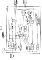
次に、本発明の一実施例として、図22で説明した検索方式をハードウェアで実現する場合の構成例について、図23、図24を用いて説明する。
【0144】
図23に経路検索処理部400をハードウェアで構成した場合の構成例を示す。経路検索処理回路200は、木構造検索回路201と、読み込みアドレス生成回路202と、メモリ制御回路206と、送信ポート情報処理回路203と、経路検索処理制御回路204とからなる。
【0145】
木構造検索回路201は、メモリ300に格納された2のp乗分木構造を検索し、次に読み込むべきノードのポインタの生成、受信パケットの経路アドレスの検査ビット値の抽出、木構造検索の終了判定、検索結果である経路情報の候補の更新を行う。また、読み込みアドレス生成回路202は、木構造検索処理時には、木構造検索回路201から出力される読み込むべきノードへのポインタ、および検査ビット値、および経路検索処理制御回路204から出力されるタイミング信号に従い、図20を用いて説明した順序でノード内の読み込みワードのメモリアドレスを生成してメモリ制御回路206に送信する。また、送信ポート情報処理時には、木構造検索回路201内のレジスタに検索結果として保持されている送信ポート情報へのポインタから送信ポート情報のメモリアドレスを生成する。また、メモリ制御回路206は、上記のメモリアドレスと、経路検索処理制御回路204から出力されるタイミング信号に従い、メモリ制御信号を生成する。また、送信ポート情報処理回路203は、メモリ300から読み出された送信ポート情報からパケットを送信すべき1つまたは複数のポート番号を生成して転送処理部504へ送信する。また、経路検索処理制御回路204は、経路検索処理回路200全体の制御(各回路の動作タイミングおよび動作状態管理など)を行う。
【0146】
上記の経路検索処理回路200を専用LSIで実現する場合、メモリ300は上記専用LSIの外部に備えても良いし、専用LSI内の内臓メモリを使用しても良い。メモリ300として専用LSIの内蔵メモリ使用すると、外部メモリを使用する場合に比べてメモリアクセス時間が短くなり、メモリ300内に格納されたルーティングテーブルの検索処理を高速に行うことができる。
【0147】
次に、経路検索処理部400の動作について図23を用いて説明する。また、木構造検索回路201の詳細動作については、図24を用いて後述する。
【0148】
木構造検索回路201は、転送処理部504から受信パケットの宛先マルチキャスト・グループIDおよび送信元IPアドレスを受け取ると、これらの値から経路アドレスを生成し、この経路アドレスとノードのマスク長の値から次ノードへのポインタを生成して、読み込みアドレス生成回路202に転送する。また、木構造検索回路201は、ノードのマスク長で示される経路アドレスの検査ビット位置の値(検査ビット値)を抽出して、読み込みアドレス生成回路202に転送する。
【0149】
読み込みアドレス生成回路202はこのノードへのポインタと、検査ビット値と、経路検索処理制御回路204からのタイミング信号を用いて、図20を用いて説明した順序でノード内の読み込みワードのメモリアドレスを生成し、メモリ制御回路206に送信する。メモリ制御回路206は上記メモリアドレスと経路検索処理制御回路からのタイミング信号を用いてメモリ制御信号を生成し、メモリ300へ出力する。上記のメモリ制御信号を受信したメモリ300は、対応するノードデータを信号線214を用いて木構造検索回路へ転送する。
【0150】
木構造検索回路201はこのノードデータを用いて、図22の処理801、802、803、804、805を行う。これらの処理の詳細は図24で後述する。図22の処理801および804に対応する判定処理において木構造検索を終了すると判定した場合は、木構造検索終了信号を経路検索処理制御回路204へ出力し、経路検索処理制御回路204は送信ポート情報読み込み処理を開始する。終了と判定されない場合は、終了と判定されるまで図22の処理801、802、803、804、805を繰り返す。
【0151】
次に、経路検索処理制御回路204は、木構造検索回路201内に保持された経路情報(エントリ有りフラグ、送信ポート情報へのポインタ)のうちのエントリ有りフラグを調べ、その値が0の場合は経路検索処理を終了し、転送処理部504へ検索結果無しという通知をする。エントリ有りフラグの値が1の場合は、送信ポート情報読み込みおよび送信ポート生成処理制御を開始し、木構造検索回路201を制御して、送信ポート情報へのポインタを読み込みアドレス生成回路202へ出力させる。読み込みアドレス生成回路202はこの送信ポート情報へのポインタと、経路検索処理回路204からのタイミング信号を用いて、読み出すべき送信ポート情報が格納されているメモリアドレスを生成し、メモリ制御回路206へ送信し、メモリ制御回路206は、上記のメモリアドレスと、経路検索処理制御回路204から出力されるタイミング信号に従い、メモリ制御信号を生成してメモリ300へ出力し、この制御信号を受信したメモリ300から信号線214上に送信ポート情報が出力される。送信ポート情報処理回路203はこの送信ポート情報を取り込み、パケットを送信すべき1つまたは複数のポート番号を生成して転送処理部504へ送信する。
【0152】
送信ポート情報の構造については、複数の送信ポート番号をポインタでつないだリスト構造や、送信ポート番号のビットマップ化などが考えられるが、リスト構造の場合、送信ポート番号が多いとメモリアクセス回数が増加し、結果として検索処理が遅くなる問題がある。送信ポート番号をビットマップ化する方法は、そのビットマップをメモリ300からバーストリードして送信ポート情報処理回路203内に保持しておき、そのビットマップをデコードして送信ポート番号を生成することにより、メモリアクセス回数を減らすことができる。
【0153】
すべての送信ポート番号を出力した後で、経路検索処理制御回路204は経路検索処理を終了し、次のパケット処理の制御を行う。
【0154】
次に、図23の木構造検索回路201の詳細を図24を用いて説明する。
【0155】
まず、図22の初段ノードリード処理800および次ノードリード処理805に対応する処理について、図24を用いて説明する。転送処理部504より信号線205を用いて送信される宛先マルチキャスト・グループアドレスおよび送信元IPアドレスは、経路アドレス生成回路207内に保持される。経路アドレス生成回路207はこれらの情報から、図5(b)で説明した60ビットの経路アドレス33を生成し、初段ノードへのポインタ生成回路208、検査ビット抽出回路209、マスク処理回路210へ出力する。
【0156】
初段ノードへのポインタ生成回路208は、予め初段ノードマスク長レジスタ229に設定されている値mに従い、受信パケットの経路アドレスの第0ビットから第(m−1)の上位mビットの値を抽出し、このmビットの値に従って初段ノードへのポインタを生成してポインタセレクタ211へ出力する。ポインタセレクタ211は、信号線226によって図23の経路検索処理制御回路204から送信される初段ノード読み込み/初段ノード以外のノード読み込み選択信号に従い、初段ノードの読み込み時は、上記の初段ノードへのポインタを選択して図23の読み込みアドレス生成回路202へ出力する。また、ポインタセレクタ211は、初段ノード以外のノードの読み込み時は、次ノードへのポインタレジスタ215に保持されている次ノードへのポインタを選択して読み込みアドレス生成回路202へ出力する。
【0157】
また、上記の処理と並行して、検査ビット抽出回路209は、初段ノード読み込み時には、検査ビット位置セレクタ212において選択されて出力される初段ノードマスク長レジスタ229の設定値mに従い、経路アドレスの第mビットから第(m+p−1)ビットまでのpビットの検査ビット値を抽出して図23の読み込みアドレス生成回路202へ出力する。また、初段ノード以外のノードの読み込み時は、後述する次ノードマスク長レジスタ216に保持されている次ノードのマスク長m1が、検査ビット位置セレクタ212において選択されて検査ビット抽出回路209に出力され、検査ビット抽出回路209は、この次ノードのマスク長m1に従い、経路アドレスの第m1ビットから第(m1+p−1)ビットまでのpビットの検査ビット値を抽出して図23の読み込みアドレス生成回路202へ出力する。
【0158】
図23の読み込みアドレス生成回路202およびメモリ制御回路206は、上記のノードへのポインタとpビットの検査ビット値を用いて、図20を用いて説明した順序でノード内の読み込みワードのメモリアドレスおよびメモリ制御信号を生成し、メモリ300は入力されたメモリアドレスに格納されているノード内の読み込みワードを信号線214に出力する。
【0159】
信号線214のビット幅が32ビットの場合、図20で説明した方式を採用すると一回のノード(の一部)の読み込みワード数は4ワードとなり、これらのデータは図20の表に示した順番で信号線214に出力され、各レジスタ(次ノードへのポインタレジスタ215、次ノードマスク長レジスタ216、経路アドレス上位レジスタ217、経路アドレス下位レジスタ222、フラグレジスタ224、送信ポート情報ポインタレジスタ230)に保持される。各レジスタの保持タイミングは経路検索処理制御回路204からの制御信号(図示していない)により制御される。次ノードへのポインタレジスタ215には次ノードへのポインタが保持され、次ノードマスク長レジスタ216には次ノードのマスク長が保持され、経路アドレス上位レジスタ217にはノードの経路アドレスの上位28ビットが、経路アドレス下位レジスタ222には経路アドレスの下位32ビットがそれぞれ保持され、フラグレジスタ224にはエントリ有りフラグが保持され、送信ポート情報ポインタレジスタ230には送信ポート情報へのポインタが保持される。
【0160】
次に、図22の経路アドレス一致比較処理801に対応する処理について、図24を用いて説明する。初段ノード読み込み時には、マスク長セレクタ228を介して初段ノードマスク長レジスタ229の設定値がマスク処理回路210に入力する。
【0161】
初段ノード以外のノード読み込み時には、マスク長セレクタ228を介してマスク長レジスタ227に保持されているノードのマスク長がマスク処理回路210に入力する。このマスク長レジスタ227の値は、一つ前に読み込んだノードに格納されている次ノードのマスク長の値であり、次ノードマスク長レジスタ216に保持されていたものである。次ノードマスク長レジスタ216の値は、ノードの読み込み毎に更新されるため、更新される前に、現在読み込んでいるノード(以下、現ノードと呼ぶ)の経路アドレス一致比較処理に使用する現ノードのマスク長をマスク長レジスタ227に保持しておく。
【0162】
マスク処理回路210は、これらのマスク長だけ上位ビットから有効とするマスクを生成し、このマスクと、経路アドレス生成回路207から出力される受信パケットの経路アドレスとの論理積をとり、その結果(以下、マスクした受信パケットの経路アドレスと呼ぶ)を一致比較回路213に出力する。また、経路アドレス上位レジスタ217、経路アドレス下位レジスタ222に保持されているノードの経路アドレスの上位28ビット、下位32ビットはこの順に連結され、ノードの経路アドレスとして一致比較回路213に入力される。一致比較回路213は、このノードの経路アドレスと、上記で説明した、マスクされた受信パケットの経路アドレスとを比較し(以下経路アドレス比較と呼ぶ)、その結果が不一致となる場合には不一致信号を信号線218を用いて木検索終了判定回路219に転送する。木検索終了判定回路219は上記不一致信号を受信し、木構造検索終了信号を図23の経路検索処理制御回路204に送信する。
【0163】
また、マスク長レジスタ227の値は、上記の経路アドレス比較が行われた後、次ノードマスク長レジスタ216に保持されている次ノードのマスク長の値によって更新され、次のノードの読み込み時の経路アドレス比較に使用される。
【0164】
次に、図22の処理802、および803に対応する処理について、図24を用いて説明する。
【0165】
一致比較回路213における経路アドレス比較の結果一致した場合、一致比較回路213は信号線220を用いて一致信号を更新判定回路221に出力する。この一致信号が更新判定回路221に入力され、かつ、フラグレジスタ224に保持されているエントリ有りフラグの値が1の場合(図25の812)のみ、更新判定回路221は更新信号をフラグレジスタ223および送信ポート情報へのポインタレジスタ225に出力する。更新信号を受信したフラグレジスタ223は、フラグレジスタ224に保持されているエントリ有りフラグを新たに保持し、同じく更新信号を受信した送信ポート情報へのポインタレジスタ225は、送信ポート情報ポインタレジスタ230に保持されている送信ポート情報へのポインタを新たに保持する(図22の経路情報更新処理803)。エントリ有りフラグの値が0の場合は更新判定回路221は更新信号を送信しないので、フラグレジスタ223および送信ポート情報へのポインタレジスタ225は更新処理を行わない(図22の813)。
【0166】
経路情報として上記のフラグおよび、送信ポート情報へのポインタ以外の情報を追加する必要がある場合は、木構造のノード内にそれらの情報を追加し、それらの情報を保持、更新するレジスタを新たに追加すればよい。
【0167】
次に、図22の次ノードへのポインタがNULLかどうかの判定処理804に対応する処理について、図24を用いて説明する。次ノードへのポインタレジスタ215内に保持されている次ノードへのポインタは木検索終了判定回路219に入力される。この次ノードへのポインタがNULLの場合、木検索終了判定回路219は図23の経路検索処理制御回路204に木検索終了信号を出力する。
【0168】
以上、図23の木構造検索処理回路201の詳細動作を図24を用いて説明したが、ハードウェアで構成するため、図22の木構造検索処理の中の801、802、803、804、805の各処理は逐次処理をする必要はなく、各処理に必要なデータが各レジスタ215、216、217、222、224、230に保持された後に、各処理を開始すればよく、上記の各処理を並列処理を行うことにより、高速に木構造の検索を行うことができる。
【0169】
【発明の効果】
マルチキャスト経路検索において検索のキーとなる宛先マルチキャスト・グループアドレスと送信元IPアドレスをこの順に連結して一つの経路アドレスとして定義し、この経路アドレスのビットパターンに従い、マルチキャストルーティングテーブルを2分木に構成することにより、エントリ数が増大しても検索時間は増加しない検索処理を行うことができる。
【0170】
また、検索木を構成する各ノードを、従来の方法である2分木ノードから4分木、8分木、あるいはそれ以上と、枝別れの数を2のべき乗で増やすことにより、1つのノードで1ビットでなく、連続する2ビット、3ビット、あるいはそれ以上のビット数を同時に検査でき、検索終了までに辿るノードの数が減り、経路検索処理の高速化を図る効果がある。
【0171】
図25に、エントリ数に対する従来技術2のハッシュ方式のマルチキャスト経路検索の処理性能900、および本発明の2分木方式のマルチキャスト経路検索の処理性能901、2のp乗分木方式のマルチキャスト経路検索の処理性能(例として、4分木方式の性能902、8分木方式の性能903)を示す。ハッシュ方式では、エントリ数に反比例して処理性能が劣化するのに対し、2分木方式および2のp乗分木方式ではエントリ数に依存せず一定となる。また、2分木方式に対し、4分木方式は2倍の性能を実現でき、また、8分木方式では3倍の性能を実現できる。
【0172】
さらに、上記の経路アドレスとして、マルチキャスト・グループアドレス自体ではなく、マルチキャスト・グループアドレスの下位28ビットのマルチキャスト・グループIDと送信元IPアドレスをこの順に連結したものを採用し、この経路アドレスのビットパターンに従い、マルチキャストルーティングテーブルを2分木あるいは2のp乗分木に構成することにより、検索木の深さを決定する経路アドレスのビット数を4ビット減らし、ノードを渡る最大回数を減らすことができる。
【0173】
また、4分木、8分木、あるいは一般に2のp乗分木を構成するときに、1つの2分木ノードと、その直下につながる(p−1)段分の合計(2のp乗−1)個分の2分木ノードを一つの2のp乗分木ノードにまとめ、まとめられる最下段の2の(p−1)乗個の2分木ノードに、それより上段のノードに割り付けられていた経路データを埋め込むことにより、まとめる前には2分木ノード換算で(2のp乗−1)個分のメモリ量だったものを、2の(p−1)乗個分のメモリ量に減らす効果がある。
【0174】
さらに、2分木ノードを2のp乗分木にまとめる際、送信ポート情報を検索木のノードから分離して記憶手段の別領域に格納し、検索木のノードには上記送信ポート情報の格納領域へのポインタを保持することで、エントリが割り当てられている2分木ノードと、エントリが割り当てられていない2分木ノードのデータ量を同じにし、これらの2分木ノードをまとめて2のp乗分木ノードを構成する際に、2のp乗分木ノードのメモリ量の削減と、各2のp乗分木ノードのメモリ量の統一を図ることができる
また、この2分木を複数個併せた形で構成した4分木、8分木、あるいはそれ以上の枝別れ数のノードを、検索のために読むときにノード全てを読むのではなく、必要な部分のみを読むようにすることにより、ノードが大きくなることによるデータの読み込み時間の増大を防ぎ、経路検索処理の高速化を図る効果がある。
【0175】
また、各ノードに、そのノード自体のマスク長ではなく、そのノードのすぐ下につながるノードのマスク長を格納することにより、ノードのマスク長をノードのデータを読む前に知ることができ、ノードのデータを読む前に、ノードのどの部分を読み込めば良いかが分かり、必要な部分のみを読むことができるようになり、ノードが大きくなることによるデータの読み込み時間の増大を防ぎ、経路検索処理の高速化を図る効果がある。
【0176】
また、各ノードの先頭に、そのノードにエントリが割り付けられているか否かを示すフラグを設け、最初に、このフラグを読み込み、エントリが割り付けられていないノードでは、経路情報を読み込まないようにすることにより、データの読み込み時間が短縮され、経路検索処理の高速化を図る効果がある。
【0177】
また、経路アドレスの上位数ビット分、ノードをメモリ上の決まった位置に展開し、受信パケットの経路アドレスの上位数ビットに従い、ノードが格納されている位置を直接にアクセスすることは、検索処理時間を無くし、経路検索処理の高速化を図る効果がある。
【0178】
また、上記の高速化手段をハードウェアで構成することにより、経路検索処理の高速化を図る効果がある。
【図面の簡単な説明】
【図1】本発明の一実施例であるパケット中継装置の例であるルータのブロック図。
【図2】一般的なネットワークの構成例を示す図。
【図3】IPアドレスの構成、およびクラスDのIPアドレスの構成、およびIPパケットのパケットヘッダフォーマット。
【図4】一般的なルータの構成例を示す図。
【図5】本発明で定義する経路アドレスの構成図。
【図6】経路アドレス長3ビットの場合の全てのノードがある2分木。
【図7】経路アドレス長3ビットの場合のマルチキャストルーティングテーブルの例。
【図8】図6においてエントリが割り付けられておらず、かつ、エントリ付きのノードへの途中経路にもなっていないノードを取り除いた木。
【図9】経路アドレス32ビットの場合のマルチキャストルーティングテーブルの例。
【図10】図9に示したマルチキャストルーティングテーブルに対応する木。
【図11】図10において枝別れもエントリの割り付けも無いノードを取り除いた木。
【図12】2分木ノードのデータ構造を示す図。
【図13】2分木から8分木への変形時に一つの8分木ノードにまとめられる2分木ノードを囲んだ木。
【図14】マスク長が0ビットから始まらないようにビット位置を区切った場合に最初のノードをメモリ上に展開することにより区切り位置までのビットの検索を行う木。
【図15】先頭のさらに多くのビット数の検索時間を省いた木。
【図16】2分木から4分木への変形時に1つの4分木ノードにまとめられる2つの2分木ノードを2つの2分木ノード分につぶした木。
【図17】1つの4分木ノードにまとめられる3つの2分木ノードの、2つの2分木ノードへのつぶし方。
【図18】1つの8分木ノードにまとめられる7つの2分木ノードの、4つの2分木ノードへのつぶし方。
【図19】4分木ノードのデータ構造を示す図。
【図20】ノードの大きさが大きくなったときにノードデータリード時間の増大を防ぐために1つのノード全てを読み込まずに一部だけを読み込む方法を示す図。
【図21】条件によっては読み込む必要が無い要素を、条件に従い読み込まないようにすることで読み込みの時間を削減することで高速化を図る方法を示す図。
【図22】本発明の一実施例である経路検索処理部の検索処理フローチャート。
【図23】本発明の一実施例である経路検索処理部のブロック図。
【図24】本発明の一実施例である、木構造のマルチキャストルーティングテーブル検索を行う木構造検索処理回路のブロック図。
【図25】ハッシュ方式、2分木方式、2のp乗分木方式の、エントリ数に対する処理性能を示す図。
【符号の説明】
T11、T12、T21、T22、T31、T32、T41、T42、T51、T52・・・ネットワーク上でパケットを送受信する端末、SN1〜SN5・・・各端末が属するサブネットワーク、R1〜R3・・・サブネットワークを相互に接続するルータ、P11、P12、P13、P21、P22、P23、P24、P31、P32、P34、P35・・・各ルータのポート、1・・・IPアドレス、2・・・サブネットワークを識別するサブネットワークアドレス、3・・・ネットワーク内の端末を識別するホストアドレス、4・・・クラスDのIPアドレス、5・・・クラスDであることを示すクラスDのIPアドレスの上位4ビット、6・・・マルチキャスト・グループID、7・・・IPパケットヘッダの送信元アドレスフィールド、8・・・IPパケットヘッダの宛先アドレスフィールド、11-i(=1〜N)・・・ルータの入力ポート、12-i(=1〜N)・・・ルータの出力ポート、13-i(=1〜N)・・・ルーティング処理部、14・・・スイッチ、15-i(=1〜N)・・・通信制御部、16・・・管理部、32・・・マルチキャスト・グループアドレス、送信元IPアドレスの順に連結して生成した経路アドレス、33・・・マルチキャスト・グループID、送信元IPアドレスの順に連結して生成した経路アドレス、60・・・経路アドレス長3ビットの場合の受信パケットの経路アドレスの一例、40〜54、62〜65、70〜84、90〜95、100〜104、130〜144・・・木を構成するノード、61・・・枝別れもエントリの割り付けも無いノードの長い列、110〜113、115・・・2分木ノードを構成する32ビットを単位とするワード、114・・・送信ポート情報、120〜127・・・4分木ノードを構成する32ビットを単位とするワード、200・・・経路検索処理回路、201・・・木構造検索回路、202〜204、206・・・経路検索処理回路を構成する各回路、205・・・転送処理部、経路検索処理部間の信号線、207〜213、215〜230・・・木構造検索回路を構成する各回路および信号線、226・・・経路検索処理制御回路からの読み込みノード(初段ノードかそれ以外か)選択制御信号線、300・・・マルチキャストルーティングテーブルが格納されるメモリ、400・・・経路検索処理回路とメモリから構成される経路検索処理部、500、604、605・・・ルータに接続されるネットワークの例、501、602、603・・・通信制御部、502・・・パケットデータのメモリ格納およびメモリからの読み出しを制御する制御回路、503・・・パケットデータが格納されるメモリ、504・・・パケット転送処理部、505・・・複数のパケット処理部および管理部が接続されるスイッチ、600・・・パケット処理部、601・・・ルータ全体の管理を行う管理部、700・・・ルータ。[0001]
BACKGROUND OF THE INVENTION
The present invention relates to a packet relay apparatus that interconnects a plurality of networks and relays a packet, and more particularly to a multicast packet next transfer destination search method.
[0002]
[Prior art]
As the number of users increases, traffic (packets) flowing through the Internet has increased rapidly, and the Internet has become larger and faster. In addition, in the current Internet (Internet Protocol packet communication network: hereinafter referred to as IP network), not only conventional data communication, but also real-time applications (uses) such as Internet telephony and Internet broadcasting have appeared, and voice communication functions Importing and capturing of broadcasting functions are progressing. Under such circumstances, the IP multicast technology in the IP network is expected as an effective technology for distributing multimedia data such as moving images, voices, and contents on the Internet. In addition, support for IP multicast technology in a packet relay device (router) constituting an IP network and speeding up of the IP multicast technology are issues.
[0003]
In the case of unicast communication in which a router transmits a packet from a certain terminal to a specific one terminal, route information corresponding to the destination IP address in the header of the received packet (the IP address of the router or terminal to be transferred next, and Search the routing table (sending port number in the router) and send the packet. The unicast route search will be briefly described below.
[0004]
The routing table holds a plurality of information groups including the subnetwork address and subnet mask length corresponding to the destination IP address, and the above route information. Hereinafter, these information groups are referred to as entries. Here, the subnetwork indicates a subset of terminals such as a destination corporate network, for example, and the subnetwork address is an address group obtained by combining the IP addresses of the subset as address information. The subnet mask length is a value indicating how many upper bits of the IP address are the identifiers of the sub-network. The router compares the destination IP address of the received packet with a valid mask from the upper bits by the subnet mask length in the entry with the subnetwork address of the entry, and uses the route information of the matching entry as a search result. By configuring entries in units of sub-networks in this way, the number of entries in the routing table is greatly reduced, and search processing efficiency is improved. When a plurality of entries are matched, the route information of the entry having the longest subnet mask length is used as the search result. Hereinafter, this search method is referred to as the longest match search.
[0005]
In the case of multicast communication in which a packet is transmitted from a certain terminal to a plurality of specific terminals, each entry in the routing table includes a transmission source subnet address, an address mask, a multicast group address, and route information. The multicast group address is an identifier assigned to a set of a plurality of destinations (hereinafter referred to as a multicast group) to which a transmission source should transmit a packet. The router searches the routing table using the source IP address in the header of the received packet and the multicast group address contained in the destination IP address portion in the header of the received packet as keys. In the case of multicast, the route information of the entry that matches as a result of the search is composed of a plurality of transmission port numbers. The router copies the received packet according to the transmission port number and outputs it for the specific multicast group. If the load of these search processing and copy processing is heavy and the performance of multicast communication is low, the performance of the entire router that performs the forwarding processing of the multicast packet will be a factor of degradation. For this reason, high speed is required as in the normal unicast packet relay processing.
[0006]
Regarding speeding up by a load distribution processing method of a router, there is a reference in, for example, Japanese Patent Laid-Open No. 6-197111 (hereinafter referred to as “
[0007]
The search for the destination of the multicast packet in the router (hereinafter referred to as multicast route search) is described in, for example, (hereinafter referred to as “
[0008]
When receiving a multicast packet, a route search processing unit inside the router calculates a hash value from the transmission source IP address of the received packet, and searches the routing table corresponding to the hash value. Route search speed is increased by limiting the search range of the routing table according to the hash value.
[0009]
On the other hand, the Radish algorithm is known as a route search method. The Radish algorithm is described in, for example, “A technical memo of WIDE project, Kazuhiko Yamamoto, Akira Kato and Akira Watanabe, Radish-A Simple Table Structure for CIDR” (hereinafter referred to as “
[0010]
This Radish type routing table has entries in a binary tree structure to speed up the search. Specifically, an entry is allocated to each node of a binary tree structure in which a plurality of vertices (nodes) having pointers on the left and right are connected by pointers with the most significant bit of the IP address format as the root (tree structure root) side Is configured. When searching this binary tree structure, the destination IP address of the received packet is inspected bit by bit from the upper bits, and either the left or right pointer of each node is determined according to the value of the inspected bit (0 or 1). Select to move to the next node. By such a search, the node to which the target entry is assigned can be reached.
[0011]
Since the
[0012]
When matching a plurality of entries with different mask lengths as described in the explanation of the unicast route search above, in the search of the routing table of the Radish method of the
[0013]
In addition, as a technology for performing high-speed unicast route search using the Radish method of Conventional Technology 3, "High-speed search method using IP routing table hardware" 1998 IEICE Communication Society Conference (hereinafter "Prior Art 4") There is.)
[0014]
In the
[0015]
In addition, as a technology that performs high-speed unicast route search using the Patricia Trie search algorithm similar to the Radish method, “Development of a high-speed IP address resolution H / W engine” 1998 IEICE Communication Society Conference (hereinafter “
[0016]
As a technology to further speed up the unicast route search by the Patricia Trie search algorithm of the
[0017]
Japanese Patent Laid-Open No. 10-222535 (hereinafter referred to as “
[0018]
[Problems to be solved by the invention]
Currently, IP multicast communication is only used in a limited manner in a multicast network virtually constructed on the Internet. The network scale is not so large, and multicast communication search processing and transfer processing do not cause deterioration in the transfer performance of the router. However, in the future, as applications using the multicast function on the Internet become widespread, the number of entries in the multicast routing table held by the router increases accordingly. Therefore, it is required to increase the speed of the routing table search process under conditions where the number of entries is large.
[0019]
[0020]
In this regard, according to the method of performing the unicast route search using the above-described Radish algorithm, there is an advantage that the search processing time does not increase even if the number of entries in the routing table increases as compared with the hash method.
[0021]
However, the
[0022]
[0023]
Also, the
[0024]
Accordingly, a first object of the present invention is to propose a means for speeding up multicast packet route search processing with regard to multicast packet relay processing.
[0025]
The second object of the present invention is to propose means for applying the binary tree search method based on the Radish algorithm to multicast route search.
[0026]
A third object of the present invention is to apply a route search method in which the number of times of tracing a node is less than the number of bits and the maximum search time is short even when the number of search key bits is large, to the multicast route search method. Is to propose.
[0027]
A fourth object of the present invention is to propose a circuit configuration that performs a route search process at high speed according to a binary tree search method of a multicast routing table based on the Radish algorithm.
[0028]
[Means for Solving the Problems]
In order to achieve the above object, the present invention has the following methods and means.
[0029]
In multicast path search using the IP address of the packet source terminal (source IP address) and the group address (destination multicast group address) of the multicast group to which the terminal to which the packet should be transmitted belong as a search key, The source IP address and destination multicast group address are concatenated and defined as one route address, and the multicast routing table is constructed in a binary tree according to the route address bit pattern, and the source IP address of the received multicast packet And the destination multicast group address are checked bit by bit from the upper bits of the path address, and a search tree having a binary tree structure is searched according to the value of the check bit.
[0030]
In addition, with respect to the above route address, a route address is defined by connecting the source IP address and the destination multicast group address in the order of the destination multicast group address and the source IP address, and according to the bit pattern of this route address. The multicast routing table is configured as a binary tree.
[0031]
Further, by increasing each node constituting a binary tree-type search tree from a binary tree node to a quadtree, octree, or generally 2 to the power of p, and the number of branching by a power of 2, A multicast routing table is configured in a p-th tree structure of 2 and a route address obtained by concatenating a destination multicast group address and a source IP address of a received multicast packet in this order is not one bit but continuous in one node. Two bits, three bits, or generally p bits are checked at the same time, and a multicast routing table having a p-th power tree structure of 2 is searched according to the value of the consecutive bits.
[0032]
Further, as the above route address, not the multicast group address itself but the lower 28 bits multicast group ID of the multicast group address and the source IP address concatenated in this order are adopted, and the bit pattern of this route address Thus, the multicast routing table is configured as a binary tree or a p-th power tree of 2.
[0033]
In order to reduce the amount of memory constituting the search tree, when constructing a p-th power of 2 tree, the sum of one binary tree node and (p−1) stages directly below it (p of 2) Multiplier-1) binary tree nodes are grouped into a single p-th power tree node, and the lowermost 2 (p-1) power binary tree nodes are grouped together, and the nodes higher than that By embedding the entry data allocated to, the p-th power tree node of 2 is configured in the form of the binary tree nodes combined with the power of 2 (p−1), and the binary tree is further formed. When combining multiple, have only one common node data element.
[0034]
Also, when collecting binary tree nodes into 2 p-th power tree, the transmission port information is used to reduce the memory amount of 2 p-th power tree nodes and unify the memory amount of each 2 p-th power tree nodes. Is separated from the node of the search tree and stored in another area of the storage means, and the search tree node holds a pointer to the storage area of the transmission port information, so that the binary tree node to which the entry is assigned The binary tree nodes to which no entry is assigned have the same data amount, and these binary tree nodes are combined to form a p-th power tree node of 2.
[0035]
Further, regarding the mask length indicating the bit position to be inspected of the path address, the mask length of the node connected directly below the node is not stored in each 2 p-th power tree node, but stored in the node. As a result, when reading node data from the storage means storing the search tree data to perform the route search processing, the entire node data is not read, but is stored in the node read immediately before. Using the mask length, only necessary portions of the node data are selected and read.
[0036]
In addition, a flag indicating whether or not an entry is assigned to the node is provided at the head of each node. This flag is read first, so that route information is not read in a node to which no entry is assigned. To do.
[0037]
Further, 2 m 2 p-th power tree nodes corresponding to the upper m bits of the path address are expanded to fixed positions on the storage means, and each expanded node is assigned the 0th path address. The values that can be taken from the bit to the (m−1) th bit are made to correspond one-to-one, and at the time of search, the node is selected according to the value of the 0th bit to the (m−1) th bit of the path address.
[0038]
In addition, the destination address and the source address are concatenated in this order to form a route address, and 2 m raised 2 p-th power tree nodes corresponding to the upper m bits of the route address are stored at fixed positions. The subsequent trees have storage means configured to store in a 2 p-th power tree structure, and at the time of route search, from the 0th bit of the route address obtained by concatenating the destination address and the source address of the received multicast packet in this order. According to the value of (m−1) bits, one of the nodes expanded at a fixed position in the memory is selected, and after the m-th bit of the route address, the route address is checked bit by bit and the power of 2 is multiplied by 2 It has a circuit that searches the multicast routing table configured in the tree.
[0039]
Other problems to be solved by the present application and the means for solving the problems will be clarified in the section of “DETAILED DESCRIPTION OF THE INVENTION” and the drawings of the present application.
[0040]
DETAILED DESCRIPTION OF THE INVENTION
Embodiments of the present invention will be described below with reference to the drawings.
[0041]
First, a general network configuration and a packet relay operation in the network will be described with reference to FIGS.
[0042]
The network shown in FIG. 2 includes terminals (T11, T12, T21, T22, T31, T32, T41, T42, T51, T52) that transmit and receive packets, and sub-networks (SN1 to SN5) that interconnect the terminals. And routers (R1 to R3) for connecting the sub-networks to each other. The router R1 has ports P11, P12, and P13, the router R2 has ports P21, P22, P23, and P24, and the router R3 has ports P31, P32, P34, and P35. Each terminal is assigned an address as an identifier. For example, each terminal on the IP network is assigned a 32-bit IP address. This IP address will be described with reference to FIG. The IP address (1) shown in FIG. 3A is composed of a sub-network address (2) and a host address (3).
[0043]
The subnetwork address is an identifier of the subnetwork, and the host address is an identifier of a terminal in the subnetwork. The number of bits of the subnetwork address is indicated by the subnet mask length, and by subtracting the effective mask (subnet mask) from the upper bits by the subnet mask length and the logical product of each bit of the IP address, You can get an address.
[0044]
Next, a packet relay operation will be described with reference to FIG. 2 for unicast communication in which a packet is transmitted from a certain terminal to one specific terminal. As an example, a case where a unicast packet is transmitted from the terminal T11 to the terminal T22 will be described. The header format of the transmitted packet is shown in FIG. In FIG. 3C, the source IP address field (7) stores the IP address of the source terminal T11, and the destination IP address field (8) stores the IP address of the destination terminal T22. The router R1 that has received the unicast packet from the terminal T11 checks the destination IP address field in the packet header, the destination terminal T22 is on the subnetwork SN2, and the subnetwork SN2 is connected via the router R2. The IP address (referred to as the next hop IP address) of the router R2 to which the packet is to be transmitted and the port P12 to be transmitted are determined, and the packet is output. The router R2 that has received the unicast packet from the router R1 checks the destination IP address field in the packet header, the destination terminal T22 is on the subnetwork SN2, and the subnetwork SN2 is directly connected to the router R2. The next hop IP address (in this case, the IP address of the terminal 22) and the port P22 to be transmitted are determined, and the packet is output.
[0045]
Next, the configuration of the router and the relay operation of the router's unicast packet will be described with reference to FIG. 4 includes an input port 11-i (= 1 to N), an output port 12-i (= 1 to N), a routing processing unit 13-i (= 1 to N), a
[0046]
The unicast routing table is created by the
[0047]
Next, a packet relay operation will be described with reference to FIG. 2 for multicast communication in which a packet is transmitted from a certain terminal to a plurality of specific terminals. As an example, a case where a multicast packet is transmitted from the terminal T11 to terminals (T21, T31, T32, T41, T42, T51) belonging to a specific multicast group will be described. A multicast group is identified by a class D IP address (multicast group address). The structure of this class D IP address is shown in FIG. The class D IP address (4) is composed of upper 4 bits (5) “1110” indicating class D and a 28-bit multicast group ID (hereinafter referred to as GID) (6). A multicast group identified by the above multicast group address can span a plurality of sub-networks. Also, the member configuration of terminals belonging to the group is dynamic, and the terminals can freely join and leave the multicast group.
[0048]
The IP address of the source terminal T11 is stored in the source IP address field (7 in FIG. 3C) in the header of the multicast packet transmitted from the terminal T11 to a certain multicast group, and the destination IP address field ( In FIG. 3C, 8), unlike the case of the unicast packet, the destination multicast group address is stored. Unlike the case of the unicast packet, the router R1 that has received the multicast packet from the terminal T11 checks two fields of the source IP address field and the destination IP address field in the packet header, and the source of the multicast packet Recognizing that the terminal T11 is on the subnetwork SN1, and further transmitting packets from this subnetwork SN1 to all terminals belonging to the destination multicast address, the router R1 should transmit packets P12, P13 The packet is copied to the port and output. The router R2 that has received the multicast packet from the router R1 performs the same inspection as R1, recognizes that the source terminal T11 of this multicast packet is on the subnetwork SN1, and further determines that the terminal belonging to the destination multicast address is In order to transmit the packet to the existing sub-networks SN2 and SN3, the router R2 determines transmission ports P22 and P23 to which the packet is to be transmitted, and copies and outputs the packet to the port. Similarly, the router R3 determines ports P34 and P35 to which the packet received from R1 is to be transmitted, and copies and outputs the packet to the port.
[0049]
Next, the relay operation of the multicast packet of the router will be described with reference to FIG. When the multicast packet described above is input from the input port 11-i, the routing processing unit 13-i uses the source IP address and destination IP address (destination multicast address) in the packet header as a multicast routing table. Search for. By this search, the number (transmission port number) of one or a plurality of output ports 12-i to be output is determined, the received packet is copied, each transmission port number is added to the packet and sent to the
[0050]
The multicast routing table is created by the
[0051]
Next, as an embodiment of the present invention, an example of the overall configuration of the router will be described with reference to FIG.
[0052]
First, the configuration of the
[0053]
Furthermore, each
[0054]
Next, the configuration of the
[0055]
Next, multicast packet relay processing in the
[0056]
The
[0057]
The
[0058]
The present invention relates to speeding up of the route
[0059]
First, the binary tree search method of
[0060]
As described in the prior art, when performing a multicast route search, the multicast routing table is searched using the source IP address and destination multicast group address in the header of the received packet as search keys. That is, the route from the source to the destination of the multicast packet is identified by the combination of these two pieces of information.
[0061]
Therefore, by concatenating the source IP address and the multicast group address, defining this as a route address, and constructing a multicast routing table with this route address and route information pair as an entry, this route address is used as a key. Multicast routing table can be searched.
[0062]
Of the above two addresses, with regard to the multicast group address, since one address is assigned to one multicast group, the multicast group address held in the entry when the routing table is searched And a coincidence comparison.
[0063]
However, of the above two addresses, regarding the source IP address, the source IP address of the received packet is obtained by applying a valid mask from the upper bits by the subnet mask length held in the entry and held in the entry. The search result is the route information of the entry that matches the transmitted source subnetwork address. In this case, it is necessary to perform the longest match search as in the unicast route search.
[0064]
From the above, the connection order of the source IP address and the multicast group address is defined as a route address in the order of the multicast group address and the source IP address, and multicast routing is performed according to the bit pattern of this route address. By configuring the table in a binary tree structure, the longest match search can be performed for the route address in the same manner as the unicast route search method using the Radish method described in the
[0065]
FIG. 5 shows route addresses used when searching a multicast routing table composed of binary trees. Note that this route address is also used in a 2 p-th tree search method described later. The
[0066]
Next, a method for configuring a multicast routing table into a binary tree using the above route address will be described. Since the concept of the tree structure does not depend on the number of bits of the route address, for the sake of simplicity, description will be made assuming that the multicast group ID is 1 bit and the source IP address is 2 bits. In this case, the route address is 3 bits.
[0067]
FIG. 6 shows an example of a binary tree structure. As shown in FIG. 6, each node has a route address mode aaa, a route address mask length n, and pointers to two nodes below the node. Here, the route address mask length is a value indicating how many upper bits of the route address of the node are valid, and also indicates the check bit position of the route address of the received packet at the node. A pair of a route address and a route address mask is represented by the notation mode aaa: n. This notation represents a route address with a mask.
[0068]
Each node is called a node with a route address mask length of 0 bit, 1 bit, 2 bits, and 3 bits in order from the top of the tree.
[0069]
In the node (40) having the route address mask length of 0 bit, the 0th bit of the route address indicated by the value of the route address mask length is checked, and the left / right pointer is traced according to whether the value is 0 or 1. To move to a node (41, 42) having a path address mask length of 1 bit. In the node having a path address mask length of 1 bit, the path address is obtained by following the left / right pointer according to whether the first bit of the path address is 0 or 1. Moving to a node with a mask length of 2 bits (43, 44, 45, 46), a node with a route address mask length of 2 bits follows the path by following the left / right pointer according to whether the second bit of the route address is 0 or 1. Move to a node (47, 48, 49, 50, 51, 52, 53, 54) with an address mask length of 3 bits.
[0070]
When the pointer is traced according to whether each bit is 0 or 1 in order from the node (40) having a route address mask length of 0 bits for this route address to be searched, the route address of the node having the route address mask length of 0 bits has a route address. Nodes (41, 42) having a route address mask length of 1 bit are passed when the bits of the route address are 0xx and 1xx in order from the left, and nodes (2 bits of route address mask length) ( 43, 44, 45, 46) are passed in order from the left when each bit of the route address is 00x, 01x, 10x, 11x, and a node (47, 48, 49, 50, 51, 51) having a route address mask length of 3 bits. 52, 53, 54), each bit of the route address is 000, 001, 010, 011, 100, 101, 110, 111 in order from the left. Passing the case. Here, x indicates that the bit value may be either 0 or 1.
[0071]
Therefore, the node (40) having the route address mask length of 0 bit passes when the route address belongs to the masked route address 000: 0, and the node (41, 42) having the route address mask length of 1 bit has the route address of Nodes (43, 44, 45, 46) having a route address mask length of 2 bits are passed through when the route addresses belong to masked route addresses 000: 1 and 100: 1, respectively. Nodes (47, 48, 49, 50, 51, 52, 53, 54) that pass when the addresses belong to 010: 2, 100: 2, 110: 2 and the route address mask length is 3 bits are masked respectively. Passed if it belongs to the attached route address 000: 3, 001: 3,..., 111: 3.
[0072]
As described above, each node of this tree has a one-to-one correspondence with all masked route addresses having different route address and route address mask lengths.
[0073]
In the above binary tree, the entries are allocated to the
[0074]
When the path address of the received packet is 011 (60 in FIG. 6), when the pointer is traced from the top of this tree according to whether each bit is 0 or 1, the
[0075]
As can be seen from the above search method, the
[0076]
When the above method is used and the path address length is assumed to be 32 bits, if a binary tree corresponding to the path table shown in FIG. 9 is configured, a
[0077]
In the example of FIG. 10, the
[0078]
Next, a method for searching a degenerated binary tree will be described.
[0079]
In the example shown in FIG. 11, after checking the 0th bit at the
[0080]
Here, in the example shown in FIG. 11, the 0th bit has already been tested, and the branch having the same 0th bit has been selected, so it always matches. In general, every time a node is reached, it is checked whether or not the correct node is reached. For bits from the 0th bit to the route address mask length of the node, the route address of the received packet and the node Since it is guaranteed that the route address is equal, when reaching the next node, regardless of what bit was checked before, with respect to the bits from the 0th bit to the route address mask length of the node, It may be checked whether the route address of the received packet is equal to the route address of the node.
[0081]
Next, the data structure of the nodes constituting the binary tree described above will be described with reference to FIG. In FIG. 12A, the
[0082]
FIG. 12A shows an example in which the transmission port information 114 is held in the data structure of the binary tree node. FIG. 12B shows an example in which the transmission port information 114 is separated from the binary tree node structure and a pointer 115 to the separated transmission port information is held. The transmission port information indicates one or a plurality of transmission port numbers to which the received multicast packet is to be transferred. When the number of router ports is large, several words are required. Accordingly, as shown in FIG. 12A, when the transmission port information 114 is held in the binary tree node structure, a binary tree node to which an entry is allocated and a binary tree node to which no entry is allocated are used. , The size will be very different. If the size of the nodes is different in this way, the number of bits required for the pointer to the next node in the node increases, and the processing for calculating the actual memory address from the pointer becomes complicated. There may be a problem that the configuration becomes complicated.
[0083]
When the transmission port information is separated from the node as shown in FIG. 12B and the node holds a pointer 115 to the transmission port information, the size of the node is constant regardless of whether or not an entry is assigned. This has the advantage of simplifying the hardware configuration.
[0084]
Next, the 2 p-th tree search method of
[0085]
In the binary tree method described above, there are two branch destinations in one node, and search is performed bit by bit. The number of bits of the search key matches the number of nodes (the maximum value) traced during the search. Therefore, the maximum search time is expressed by (Equation 1).
[0086]
(Maximum search time) = (Processing time of one node) × (Number of bits of search key) (Equation 1)
That is, the maximum search time is proportional to the number of bits of the search key. This maximum search time is required to be further shortened and speeded up.
[0087]
Therefore, in the 2 p-th power tree method described below, the search time is shortened to 1 / p compared to the conventional case by providing a branch destination of 2 p power at one node and simultaneously searching by p bits. To do. Hereinafter, a node having a 2 p power branch destination in one node is referred to as a 2 p power tree node.
[0088]
The p-th power tree node of 2 is created by modifying a tree composed of the binary tree nodes described in the binary tree method. The tree transformation method consists of a binary tree node having a path address mask length of n and a binary tree having a path address mask length of (n + 1) bits to (n + p-1) bits existing under the binary tree node. A node is made to correspond to one 2 p-th tree node. Also, in the following, regarding the 2 p-th power tree nodes that are collected in association with each other as described above, the mask length n of the binary tree node that was at the vertex before the bundling is taken over, and this 2 p-th power tree node Is defined as n.
[0089]
As an example of the above-described modification method, a modification method from a binary tree to an octree is shown in FIG.
[0090]
Consider a case where an octree is formed when the number of bits of a route address is 60 bits. In this case, as a method of selecting a binary tree node corresponding to one octree, a binary tree node having a mask length of 0 to 2, 3 to 5,. In the case of an octree node (FIG. 13 (a)), each binary tree node having a mask length of 1 to 3, 4 to 6,. In the case of a branch tree node (FIG. 13B), each of the second to fourth, fifth to seventh,..., 56 to 58, 59 to 60 bit binary tree nodes is one octal tree. There are three types of nodes (Fig. 13 (c)), which can be configured in any way. However, in the whole tree, the above three types of bit position delimiters are used so that entries can be easily added and deleted. Use one of the methods.
[0091]
Of the three bit position division methods described above, except for the first division method, the mask length does not start from 0 bits, so the first bit needs to be checked separately. For this inspection, a method of developing a node having a mask length of m bits at a predetermined position on the memory (hereinafter referred to as method 3) is used.
[0092]
Hereinafter, the
[0093]
An example in which the
[0094]
In the configuration shown in FIG. 14 (a),
[0095]
Further, in the case of the bit delimiter positions shown in FIGS. 13A, 13B, and 13C, the number of octree nodes to be arranged first is not 1, 2, or 4, but 8 times these. 8, 16, 32, 64, 128, 256, which is a power of 8, 64, or generally 8 times the power of q, and the first one, twice, or generally q times of the octal node It is possible to eliminate the search time. In this case, the mask length m of the octree node developed at a fixed position in the memory is m = 3 in the case of the bit delimiter positions shown in FIGS. 13 (a), (b), and (c). × q, 1 + 3 × q, 2 + 3 × q, and the search time for the upper m bits can be saved. In the case of q = 1, that is, when the search time of one node of the octree node is eliminated, the case of the three bit delimiter positions shown in FIGS. 13 (a), (b), and (c) FIG. 15A, FIG. 15B, and FIG. 15C show how nodes are expanded on the memory.
[0096]
In FIG. 15 (a), eight octree nodes with mask length m = 3 are expanded to fixed positions on the memory, and expanded according to the total of 3 bits of the 0th to 2nd bits of the path address of the received packet. Select one of the obtained octree nodes. In FIG. 15 (b), the octtree nodes with mask length m = 1 + 3 = 4 are expanded to fixed positions on the memory, and according to the value of the total 4 bits of the 0th to 3rd bits of the path address of the received packet. , Select one of the expanded octree nodes. In FIG. 15 (c), 32 octtree nodes with mask length m = 2 + 3 = 5 are expanded to fixed positions on the memory, and according to a total of 5 bits of the 0th to 4th bits of the path address of the received packet. , Select one of the expanded octree nodes.
[0097]
The
[0098]
The
[0099]
Next, a configuration method of a quadtree node, an octtree node, a 16-tree node, or a power-of-two tree node in general will be described with reference to FIG.
[0100]
FIG. 16 shows a quadtree, which is a single binary tree node A, B, C, D, E and two binary tree nodes A0, A1, B0, B1, C0, C1, D0, immediately below it. This is an example in which a total of three binary tree nodes D1, E0, and E1 are combined into one
[0101]
FIG. 17 shows how to collapse this node in the case of a quadtree. In FIG. 17, the notation * A represents path information in an entry allocated to the node A. Also, it means that no entry is assigned to a node without the notation * A.
[0102]
If there are all three nodes in the binary tree structure (FIG. 17 (a)), if entries are assigned to all the nodes, the path information * A0, * A1 of the lower node is left and the upper node is deleted. To do. This is because if the entry of node A matches, the entry of either node A0 or node A1 will always match, so the longest match search is performed, so that the path information * A of node A is not used. is there.
[0103]
When an entry is assigned to the upper node A and an entry is not assigned only to A1 of the lower nodes A0 and A1 (FIG. 17B), the route information * A of A is stored in the node A1. To do. The same applies to the case where no entry is assigned to A0 of the lower nodes A0 and A1.
[0104]
If no entry is assigned to both the lower nodes A0 and A1 (FIG. 17C), the path information * A of A is stored in both the nodes A0 and A1.
[0105]
When there is no lower node A1 (FIG. 17 (d)), A1 is supplemented, and the route information * A of the upper node A is stored in A1, and further, no node is connected under the node A1. The pointer to the node below the node A1 is set to NULL. The same applies to the case where no entry is assigned to A0 of the lower nodes A0 and A1.
[0106]
When both the lower nodes A0 and A1 are not present (FIG. 17 (e)), both are supplemented, the route information * A of A is stored in both nodes, and the pointer to the node below both nodes is NULL. To.
[0107]
If no entry is assigned to the upper node A (FIG. 17 (f)), the node A is simply deleted.
[0108]
When no route is assigned to the upper node A and no entry is assigned to A1 among the lower nodes A0 and A1 (FIG. 17 (g)), the route of A1 is also obtained when the quadtree is used. There is no information. The same applies when no entry is assigned to A0 among the lower nodes A0 and A1.
[0109]
When no entry is assigned to the upper node A and no entry is assigned to both the lower nodes A0 and A1 (FIG. 17 (h)), both nodes A0 and A1 are formed even when the quadtree is used. There is no route information.
[0110]
When there is only the lower node A0 (FIG. 17I), the lower node A1 is supplemented. The same applies when there is only the lower node A1.
[0111]
Similarly, in the case of an octree, the seven binary tree nodes that are grouped together are crushed to the size of only the bottom four nodes. Two examples of how to crush the upper three binary tree nodes are shown in FIG.
[0112]
FIG. 18A shows an example in which all seven binary tree nodes are grouped together, but entries are allocated to only some of them. Of the four nodes at the bottom, For nodes A01 and A10 to which no entry is assigned, among the nodes connected above the node, the lowest node to which the entry is assigned, that is, the node having the longest route address mask length (A and A1, respectively) Route information * A, * A1 is stored.
[0113]
FIG. 18B shows an example in which only some of the seven binary tree nodes grouped together exist, and the nodes A01 and A10 that do not exist are first set as nodes to which no entry is allocated. In addition, route information is stored in accordance with the same rules as in FIG. Of the four lowest nodes A00, A01, A10, A11, no node is connected below the supplemented nodes A01, A10, so the pointer to the lower node is set to NULL.
[0114]
In general, in the case of a 2 p power tree, the (2 p power-1) binary tree nodes to be combined are crushed, and the bottom 2 (p-1) power nodes are collapsed. Make it just the size of the node.
[0115]
In addition, since 4, 8, 16,... Branch tree nodes handle 2, 4, 8,... Binary tree nodes collectively, one 4, 8, 16,. It is sufficient to have only one common element between the binary tree nodes summarized in (4), thereby reducing the memory amount of the 4, 8, 16,... Elements that are common among the binary tree nodes that are grouped into 4, 8, 16,... Tree nodes include the route address and length of the route address mask. As will be described later, the length is not the length of the route address mask of this node itself, but the length of the route address mask of the node immediately below this node, so there is no effect of reducing the amount of memory.
[0116]
Next, a data structure of a quadtree node will be described with reference to FIG. 19 as an example of 2 p-th power tree nodes. When configuring a quadtree node, the two binary tree nodes are grouped together, and only one common data is held in the two binary tree nodes to be combined. This common data is only the route address of the node (
[0117]
In FIG. 19, the mask length tt of the next node, the flag tt, and the pointer tt to the next node in the
[0118]
In the example shown in FIG. 12 (b), the binary tree node has a size that does not fit in 16 bytes, which is the power of 2, and is a quadtree node. By having only one route address, it can fit in just 32 bytes, which is the power of 2. If an octree node is used and only one route address is held in one node, it will fit in the size of 64 bytes and allow 4 bytes, and this area can be used to store other information. it can. If the number of binary trees combined into one is increased (ie, the value of p in the 2 p-th power tree is increased), the size of one node is further reduced with respect to the power of 2. it can.
[0119]
Thus, the hardware configuration can be greatly simplified by keeping the size of one node within the power of two. An example that can simplify the hardware configuration is shown below.
[0120]
As a first example, when a quadtree node fits in 32 bytes, even if the memory is composed of multiple banks, the memory area of one node does not cross bank boundaries, and dynamic RAM is used for the memory Even if this is done, the memory area of one node must not cross the Row address boundary.
[0121]
As a second example, when calculating the address in the memory of each element in a node (hereinafter referred to as a memory address), it is not the sum of the pointer to that node and the offset from that pointer, but the upper address of the memory address. The bits should be pointer values and the lower bits should be offset. For example, if a quadtree node fits in 32 bytes, in order to generate a memory address of an element in a node, a pointer to that node is allocated to the 5th power bit of the memory address and the element in the node May be allocated from 2 0 bits to 2 4 bits of the memory address.
[0122]
As a third example, for example, when a quadtree node fits in 32 bytes, the value of (first byte address of the next node) / 32 is held as a pointer to the next node held in each node. The amount of data can be reduced by 5 bits per pointer within one node.
[0123]
Next, for example, a node reading method when the path
[0124]
FIG. 20 shows an example of a quadtree. As already described with reference to FIG. 19, the quadtree node having a route address mask length of m bits is 2 corresponding to the case where the value of the m-th bit of the route address shown in FIG. It has a structure in which a branch tree node and a binary tree node corresponding to the case of 1 are combined. Therefore, according to the value of the m-th bit of the route address of the received packet, only the corresponding binary tree node is read, and the same as in the case of the binary tree node even if the node size increases. Read the amount of data. At this time, the route address (
[0125]
Furthermore, according to the value of the (m + 1) -th bit of the path address of the received packet, only one of the pointers to the next node existing in the binary tree node is read, thereby further reducing the amount of data to be read. Reduce.
[0126]
This method can also be used for the binary tree search method. For example, in the case of the binary tree node of the m-th bit, only one of the pointers to the two next nodes is read according to the value of the m-th bit of the path address of the received packet.
[0127]
When all the above methods are performed and the route address mask length of this node is m, the mth and m + 1 bit values of the destination address are 00, 01, 10 or 11, respectively (
[0128]
As described above, in order to read only a part of a certain node, it is necessary to know the route address mask length m of this node. The route address mask length m of this node is read at the beginning of data reading of one node, This information must be transferred to the previous node and read when reading the data of the previous node. For example, when the path
[0129]
Further, when the path address mask length m of a node is moved to the previous node, the order of reading the data of one node is changed to the path address mask length m of the next node, the pointer to the next node, By arranging the route address of the node and the pointer to the transmission port information in this order, the memory address of the first read portion of the next node can be calculated earliest.
[0130]
The pointer to the next node points to the beginning of the memory area of the next node, and the offset of the memory address from the beginning of the next node to the portion to be read first reads the mask length m of the next node, It is obtained by checking the value of the corresponding bit position of the route address of the received packet.
[0131]
Next, with reference to FIG. 21, a method of reducing the reading time and increasing the speed by preventing elements that do not need to be read depending on the conditions within one node from being read according to the conditions will be described. .
[0132]
FIG. 21 shows an example of a quadtree. As described in the description of the binary tree structure, in general, in a tree structure, not all nodes are assigned entries, and it is necessary to provide nodes at branch branches even if no entries are assigned. is there. As shown in FIG. 21, in accordance with the value of the entry present flag in the flags in the
[0133]
In this method, assuming that the mask length of this node is m, the value of the mth and m + 1 bits of the destination address is 00, the
[0134]
As described above, the respective binary search methods (method 1), the p-th power tree search method (method 2), and the method of expanding a node having a mask length of m bits on the memory (method 3) have been described. . Next, a flowchart when the route
[0135]
In the following, an example in which the
[0136]
A process 810 in FIG. 22 is a tree structure search process, and a process 811 is a transmission port information process. First, the tree structure search processing 810 will be described.
[0137]
When receiving the destination multicast group ID and the source IP address of the received packet, the route
[0138]
Next, the route
[0139]
Next, processing 802 and 803 in FIG. 22 will be described. These processes are path information update processes for realizing the longest match search. The path information includes an entry presence flag and a pointer to transmission port information in the node data output from the
[0140]
Next, the path
[0141]
Hereinafter, by repeating the above processing, it is possible to perform a route search of the 2 p-th power tree method.
[0142]
Next, the transmission port information processing 811 in FIG. 22 will be described. As a result of the tree structure search processing, the register in the route
[0143]
Next, as an embodiment of the present invention, a configuration example when the search method described in FIG. 22 is realized by hardware will be described with reference to FIGS.
[0144]
FIG. 23 shows a configuration example when the route
[0145]
The tree
[0146]
When the path
[0147]
Next, the operation of the route
[0148]
When receiving the destination multicast group ID and the source IP address of the received packet from the
[0149]
The read
[0150]
The tree
[0151]
Next, the route search
[0152]
As for the structure of the transmission port information, a list structure in which a plurality of transmission port numbers are connected with a pointer or a bitmap of transmission port numbers can be considered. However, in the case of a list structure, the number of memory access times increases when there are many transmission port numbers. As a result, there is a problem that the search processing becomes slow. The method of converting the transmission port number into a bitmap is performed by burst-reading the bitmap from the
[0153]
After outputting all the transmission port numbers, the route search
[0154]
Next, details of the tree
[0155]
First, processing corresponding to the first node read processing 800 and the next node read processing 805 in FIG. 22 will be described with reference to FIG. The destination multicast group address and the source IP address transmitted from the
[0156]
The pointer generation circuit 208 to the first node extracts the value of the (m−1) upper m bits from the 0th bit of the path address of the received packet according to the value m previously set in the first node
[0157]
In parallel with the above processing, the check
[0158]
The read
[0159]
When the bit width of the
[0160]
Next, processing corresponding to the route address
[0161]
When a node other than the first node is read, the mask length of the node held in the
[0162]
The
[0163]
Further, the value of the
[0164]
Next, processing corresponding to processing 802 and 803 in FIG. 22 will be described with reference to FIG.
[0165]
When a match is found as a result of the path address comparison in the
[0166]
When it is necessary to add information other than the above flags and pointers to the transmission port information as route information, add the information in the tree-structured node, and add a new register for holding and updating the information. Add to
[0167]
Next, a process corresponding to the
[0168]
The detailed operation of the tree structure
[0169]
【The invention's effect】
In the multicast route search, the destination multicast group address and the source IP address, which are the search keys, are concatenated in this order to define one route address, and the multicast routing table is configured in a binary tree according to the bit pattern of this route address By doing so, it is possible to perform a search process in which the search time does not increase even if the number of entries increases.
[0170]
Further, each node constituting the search tree is increased from the binary tree node of the conventional method to the quadtree, the 8-tree, or more, and the number of branching is increased by a power of 2 so that one node Thus, the number of consecutive 2 bits, 3 bits, or more can be checked at the same time instead of 1 bit, and the number of nodes to be traced by the end of the search can be reduced, which has the effect of speeding up the route search process.
[0171]
FIG. 25 shows the processing performance 900 of the hash method multicast route search of the
[0172]
Further, as the above route address, not the multicast group address itself but the lower 28 bits multicast group ID of the multicast group address and the source IP address concatenated in this order are adopted, and the bit pattern of this route address is adopted. Thus, by configuring the multicast routing table as a binary tree or a p-th power tree of 2, it is possible to reduce the number of bits of the route address that determines the depth of the search tree by 4 bits, and to reduce the maximum number of times across the nodes. .
[0173]
When a quadtree, octtree, or generally a p-th power tree of 2 is constructed, the sum of one binary tree node and (p−1) steps directly below it (2 p-th power) -1) Combine the binary tree nodes into one 2 p-th power tree node, and combine them into 2 (p-1) power binary tree nodes at the bottom, By embedding the route data that has been allocated, the memory amount of (2 to the power of p-1) in binary tree node conversion before the compilation is changed to the power of 2 (p-1). This has the effect of reducing the amount of memory.
[0174]
Further, when the binary tree nodes are combined into a p-th power tree of 2, the transmission port information is separated from the search tree node and stored in another area of the storage means, and the search tree node stores the transmission port information. By holding a pointer to the area, the data amount of the binary tree node to which the entry is assigned and the binary tree node to which the entry is not assigned are made the same. When configuring p-th tree nodes, it is possible to reduce the memory amount of 2 p-th tree nodes and unify the memory amount of each two p-th tree nodes.
Also, it is necessary not to read all the nodes when reading a quadtree, octtree, or more nodes that are composed of multiple binary trees for searching. By reading only such a portion, it is possible to prevent an increase in data reading time due to an increase in the size of the node and to speed up the route search process.
[0175]
In addition, by storing not the mask length of the node itself but the mask length of the node connected immediately below the node in each node, the node mask length can be known before reading the node data. Before you read the data, you can know which part of the node should be read, you can read only the necessary part, prevent the increase of data reading time due to the node becoming large, and route search processing Has the effect of speeding up the operation.
[0176]
In addition, a flag indicating whether or not an entry is assigned to the node is provided at the head of each node, and this flag is read first so that route information is not read in a node to which no entry is assigned. As a result, the data reading time is shortened, and the route search process is speeded up.
[0177]
In addition, the node is expanded to a fixed position in the memory for the upper few bits of the path address, and the location where the node is stored is directly accessed according to the upper bits of the path address of the received packet. There is an effect of speeding up route search processing by eliminating time.
[0178]
In addition, the speed-up means can be speeded up by configuring the speed-up means with hardware.
[Brief description of the drawings]
FIG. 1 is a block diagram of a router that is an example of a packet relay apparatus according to an embodiment of the present invention.
FIG. 2 is a diagram illustrating a configuration example of a general network.
FIG. 3 shows an IP address configuration, a class D IP address configuration, and a packet header format of an IP packet.
FIG. 4 is a diagram illustrating a configuration example of a general router.
FIG. 5 is a configuration diagram of a route address defined in the present invention.
FIG. 6 shows a binary tree with all nodes when the path address length is 3 bits.
FIG. 7 shows an example of a multicast routing table when the route address length is 3 bits.
FIG. 8 is a tree obtained by removing nodes that are not assigned entries in FIG. 6 and are not halfway paths to nodes with entries;
FIG. 9 shows an example of a multicast routing table in the case of a route address of 32 bits.
10 is a tree corresponding to the multicast routing table shown in FIG. 9;
FIG. 11 is a tree obtained by removing nodes that are neither branched nor assigned entries in FIG.
FIG. 12 is a diagram showing a data structure of a binary tree node.
FIG. 13 shows a tree surrounding binary tree nodes that are grouped into one octree tree when transforming from a binary tree to an octree.
FIG. 14 is a tree in which when a bit position is divided so that the mask length does not start from 0 bits, the first node is expanded on a memory to search for bits up to the division position.
FIG. 15 is a tree in which search time for a larger number of bits at the beginning is omitted.
FIG. 16 is a tree in which two binary tree nodes that are combined into one quadtree node when transforming from a binary tree to a quadtree are collapsed into two binary tree nodes.
FIG. 17 shows how to collapse three binary tree nodes that are grouped into one quadtree node into two binary tree nodes.
FIG. 18 is a diagram illustrating how seven binary tree nodes combined into one octree node are collapsed into four binary tree nodes.
FIG. 19 is a diagram showing a data structure of a quadtree node.
FIG. 20 is a diagram showing a method of reading only one part without reading all one node in order to prevent an increase in node data read time when the size of the node increases.
FIG. 21 is a diagram showing a method of speeding up by reducing reading time by preventing elements that do not need to be read depending on conditions from being read according to the conditions.
FIG. 22 is a flowchart of a search process performed by a route search processing unit according to an embodiment of the present invention.
FIG. 23 is a block diagram of a route search processing unit according to an embodiment of the present invention.
FIG. 24 is a block diagram of a tree structure search processing circuit for performing a tree structure multicast routing table search according to an embodiment of the present invention.
FIG. 25 is a diagram showing processing performance with respect to the number of entries in the hash method, binary tree method, and p-th power tree method of 2;
[Explanation of symbols]
T11, T12, T21, T22, T31, T32, T41, T42, T51, T52 ... Terminals that transmit and receive packets on the network, SN1 to SN5 ... Subnetwork to which each terminal belongs, R1 to R3 ... Router, P11, P12, P13, P21, P22, P23, P24, P31, P32, P34, P35 ... Port of each router, 1 ... IP address, 2 ... Sub Subnetwork address that identifies the network, 3 ... Host address that identifies the terminal in the network, 4 ... IP address of class D, 5 ... Higher order of class D IP address indicating
Claims (13)
宛先アドレスと送信元アドレスとをこの順に連結した経路アドレスのビットパターンに対応した2分木構造の検索木情報を格納する記憶手段と、
受信したマルチキャストパケットから宛先アドレスと送信元アドレスとを読み出し、その読み出した宛先アドレスと送信元アドレスとをこの順に連結して経路アドレスを生成し、その生成された経路アドレスと上記記憶手段に格納されている経路アドレスとの一致判定を行う一致判定手段とを有することを特徴とするパケット中継装置。In a packet relay apparatus that searches for route information for the multicast packet using the destination address and source address of the received multicast packet as search keys, and forwards the multicast packet to one or more ports according to the route information.
Storage means for storing search tree information of a binary tree structure corresponding to a bit pattern of a path address obtained by concatenating a destination address and a source address in this order;
The destination address and the source address are read from the received multicast packet, and the route address is generated by concatenating the read destination address and the source address in this order, and the generated route address is stored in the storage means. A packet relay apparatus comprising: a match determination means for performing a match determination with a route address that is present.
宛先アドレスと送信元アドレスとを連結した経路アドレスのビットパターンに対応した2分木構造の検索木情報を格納する記憶手段と、
受信したマルチキャストパケットから宛先アドレスと送信元アドレスとを読み出し、その読み出した宛先アドレスと上記記憶手段に格納されている経路アドレスとの一致判定を行い、その読み出した送信元アドレスと上記記憶手段に格納されている経路アドレスとの一致判定を行う一致判定手段とを有することを特徴とするパケット中継装置。In a packet relay apparatus that searches for route information for the multicast packet using the destination address and source address of the received multicast packet as search keys, and forwards the multicast packet to one or more ports according to the route information.
Storage means for storing search tree information of a binary tree structure corresponding to a bit pattern of a path address obtained by concatenating a destination address and a source address;
The destination address and the source address are read out from the received multicast packet, the matching between the read destination address and the route address stored in the storage means is performed, and the read source address and the storage means are stored. A packet relay apparatus comprising: a match determination unit configured to determine a match with a route address that has been set.
宛先アドレスと送信元アドレスとをこの順に連結した経路アドレスのビットパターンに対応した2のp乗分木構造(pは自然数)の検索木情報を格納する記憶手段と、
受信したマルチキャストパケットから宛先アドレスと送信元アドレスとを読み出し、その読み出した宛先アドレスと送信元アドレスとをこの順に連結して経路アドレスを生成し、その生成された経路アドレスと上記記憶手段に格納されている経路アドレスとの一致判定を行う一致判定手段とを有することを特徴とするパケット中継装置。In a packet relay apparatus that searches for route information for the multicast packet using the destination address and source address of the received multicast packet as search keys, and forwards the multicast packet to one or more ports according to the route information.
Storage means for storing search tree information of a 2 p-th tree structure (p is a natural number) corresponding to a bit pattern of a path address obtained by concatenating a destination address and a source address in this order;
The destination address and the source address are read from the received multicast packet, and the route address is generated by concatenating the read destination address and the source address in this order, and the generated route address is stored in the storage means. A packet relay apparatus comprising: a match determination means for performing a match determination with a route address that is present.
受信したマルチキャストパケットの宛先アドレスと送信元アドレスを検索のキーにして上記マルチキャストパケットに対する経路情報を検索し、上記経路情報に従い1つ又は複数のポートに上記マルチキャストパケットを転送するパケット中継装置において、
送信元アドレスと宛先アドレスとを、宛先アドレス、送信元アドレスの順に連結して経路アドレスとし、上記経路アドレスのビットパターンに対応した2分木構造に構成された検索木情報を格納する記憶手段と、
受信したマルチキャストパケットの宛先アドレスと送信元アドレスをこの順に連結した経路アドレスの上位ビットから1ビットづつ検査し、その検査したビットの値によって上記記憶手段に格納された2分木構造をもつ検索木を検索する回路とを有することを特徴とするパケット中継装置。A packet relay device that interconnects multiple networks and relays packets,
In a packet relay apparatus that searches for route information for the multicast packet using the destination address and source address of the received multicast packet as search keys, and forwards the multicast packet to one or more ports according to the route information.
Storage means for storing the search tree information configured in a binary tree structure corresponding to the bit pattern of the path address, by concatenating the source address and the destination address in the order of the destination address and the source address to form a path address; ,
A search tree having a binary tree structure in which the destination address and the source address of the received multicast packet are inspected bit by bit from the upper bits of the path address concatenated in this order, and stored in the storage means according to the value of the inspected bit And a circuit for searching for a packet.
受信したマルチキャストパケットの宛先アドレスと送信元アドレスを検索のキーにして上記マルチキャストパケットに対する経路情報を検索し、上記経路情報に従い1つ又は複数のポートに上記マルチキャストパケットを転送するパケット中継装置において、
送信元アドレスと宛先アドレスとを、宛先アドレス、送信元アドレスの順に連結して経路アドレスとし、上記経路アドレスのビットパターンに対応した2のp乗分木構造( p は自然数)に構成された検索情報を格納する記憶手段と、
受信したマルチキャストパケットの宛先アドレスと送信元アドレスを連結した経路アドレスの上位ビットからpビットづつ検査し、その検査したビットの値によって上記記憶手段に記憶された2のp乗分木構造をもつ検索木を検索する回路とを有することを特徴とするパケット中継装置。A packet relay device that interconnects multiple networks and relays packets,
In a packet relay apparatus that searches for route information for the multicast packet using the destination address and source address of the received multicast packet as search keys, and forwards the multicast packet to one or more ports according to the route information.
A source address and destination address are concatenated in the order of destination address and source address to form a route address, and a search constructed in a p-th tree structure (where p is a natural number) corresponding to the bit pattern of the route address. Storage means for storing information;
A search having a p-th tree structure of 2 stored in the storage means by checking p bits from the upper bits of the path address obtained by concatenating the destination address and the source address of the received multicast packet. And a circuit for searching for a tree.
送信元アドレスと宛先アドレスを、宛先アドレス、送信元アドレスの順に連結して経路アドレスとし、この経路アドレスのビットパターンに対応する2のp乗分木構造( p は自然数)をとる検索テーブルを格納する記憶手段と、
経路アドレスの上位mビット( m は自然数)に対応する2のm乗個の2のp乗分木のノードを、記憶手段上の決まった位置に展開し、それぞれのノードを、経路アドレスの第0ビットから第(m−1)ビットまでが取りうる値に1対1に対応させ、検索時には、経路アドレスの第0ビットから第(m−1)ビットの値に従って、展開されたノードの一つを選択し、第mビット以降は経路アドレスをpビットづつ検査し、その検査したビットの値によって上記記憶手段に記憶された2のp乗分木構造をもつ検索木の枝を検索する回路を有することを特徴とするパケット中継装置。A packet relay device that interconnects a plurality of networks and relays a packet, searches for the routing information for the multicast packet using the destination address and the source address of the received multicast packet as search keys, and follows the routing information. In a packet relay device that transfers the multicast packet to one or more ports,
A source address and destination address are concatenated in the order of destination address and source address to form a route address, and a search table that takes a p-th power tree structure ( p is a natural number) corresponding to the bit pattern of this route address is stored. Storage means for
The 2 m power 2 p-th power tree nodes corresponding to the upper m bits ( m is a natural number) of the route address are expanded to fixed positions on the storage means, and each node is assigned to the first address of the route address. One-to-one correspondence is made to the values that can be taken from the 0th bit to the (m−1) th bit, and at the time of retrieval, one of the expanded nodes is determined according to the value of the 0th bit to the (m−1) th bit of the path address. A circuit that checks the path address by p bits after the m-th bit and searches for a branch of a search tree having a 2 p-th tree structure stored in the storage means by the value of the checked bit A packet relay device comprising:
送信元アドレスと宛先アドレスとを、宛先アドレス、送信元アドレスの順に連結して経路アドレスとし、上記経路アドレスのビットパターンに対応した2分木構造に構成された検索木情報を格納する記憶手段と、
受信したマルチキャストパケットの宛先アドレスと送信元アドレスをこの順に連結した経路アドレスの上位ビットから1ビットづつ検査し、その検査したビットの値によって上記記憶手段に格納された2分木構造をもつ検索木を検索する回路とを有することを特徴とするパケット中継装置。A packet relay device that interconnects a plurality of networks and relays a packet, and searches the routing information for the multicast packet by using the destination address and the source address of the received multicast packet as search keys, and the routing information. In the packet relay device that forwards the multicast packet to one or more ports according to
Storage means for storing the search tree information configured in a binary tree structure corresponding to the bit pattern of the path address, by concatenating the source address and the destination address in the order of the destination address and the source address to form a path address; ,
A search tree having a binary tree structure in which the destination address and the source address of the received multicast packet are inspected bit by bit from the upper bits of the path address concatenated in this order, and stored in the storage means according to the value of the inspected bit And a circuit for searching for a packet.
検索木情報を、1つの2分木ノードと、その直下につながるp−1段分( p は自然数)の合計(2のp乗−1)個分の2分木ノードを一つの2のp乗分木ノードにまとめ、まとめられる最下段の2の(p−1)乗個の2分木ノードに、それより上段のノードに割り付けられていたエントリデータを埋め込み、2のp乗分木ノードを、2分木を2の(p−1)乗個分併せた形で構成することを特徴とするパケット中継装置。The packet relay device according to claim 8, wherein
The search tree information is divided into two binary tree nodes corresponding to a total of (2 to the power of p−1) of one binary tree node and p−1 stages ( p is a natural number) directly below it. The entry data allocated to the upper node is embedded in the 2 (p-1) th binary tree nodes at the lowest level to be collected and integrated into the multitree node, and the 2 pth power tree node Is constructed in a form in which two binary trees are combined to the power of 2 (p−1).
一つの2分木ノードと、その直下につながるp−1段分( p は自然数)の合計(2のp乗−1)個分の2分木ノードを一つの2のp乗分木ノードにまとめ、まとめられる最下段の2の(p−1)乗個の2分木ノードに、それより上段のノードに割り付けられていたエントリデータを埋め込むことにより、2のp乗分木ノードを、2分木を2の(p−1)乗個分併せた形で構成することに加え、2分木を複数個併せるときに、一つだけ持てば良い要素を一つだけ保持するようにすることを特徴とする特徴とするパケット中継装置。The packet relay device according to claim 8, wherein
One binary tree node and a total of (2 to the power of p-1) binary tree nodes of p-1 stages ( p is a natural number) connected immediately below it are converted into one 2 p power tree node. In summary, by embedding the entry data assigned to the upper node in the 2 (p-1) th power binary tree nodes in the lowest stage to be collected, the 2 p power tree nodes are set to 2 In addition to constructing a binary tree in the form of 2 (p-1) powers, when combining multiple binary trees, keep only one element that only needs to be held. A packet relay device characterized by the above.
2のp乗分木ノードを検索のために読むときにノード全てを読まずに、2のp乗分木ノードを作成するときに併せた2の(p−1)乗個の2分木ノードの内の、いずれか一つに対応するデータのみを読むようにすることを特徴とするパケット中継装置。In the packet relay device according to claim 9 or 10,
When reading a 2 p-th power tree node for searching, not all the nodes are read, and 2 (p-1) power binary tree nodes combined when creating a 2 p-th power tree node A packet relay apparatus that reads only data corresponding to any one of the above.
各ノードにそのノード自身のマスク長を格納するのではなく、そのノードの直ぐ下に繋がるノードのマスク長を格納することにより、ノードのマスク長を、そのノードのデータを読む前に知り、経路アドレスの、ノードのマスク長で示されるビット位置から、そのビット位置+p−1までの値に従い、ノードのデータの内、読み込む部分を選択することを特徴とするパケット中継装置。The packet relay device according to claim 10,
Instead of storing the node's own mask length in each node, the node's mask length is stored before reading the node's data by storing the mask length of the node directly below that node. A packet relay apparatus, wherein a portion to be read is selected from node data according to a value from a bit position indicated by a mask length of a node to a bit position + p−1.
マルチキャストパケットの宛先アドレスと送信元アドレスをこの順に連結した経路アドレスの上位ビットからpビット( p は自然数)づつ検査し、上記検査ビットの値によって記憶手段に記憶された2のp乗分木構造をもつ検索木を検索する回路を有することを特徴とする専用LSI。In the dedicated LSI that receives the header information of the multicast packet, searches for and outputs transfer information such as a transmission port for the multicast packet,
A p-multitree structure of 2 stored in the storage means by checking p bits ( p is a natural number) from the upper bits of the path address obtained by concatenating the destination address and source address of the multicast packet in this order. A dedicated LSI having a circuit for searching a search tree having
Priority Applications (5)
| Application Number | Priority Date | Filing Date | Title |
|---|---|---|---|
| JP28220598A JP3735471B2 (en) | 1998-10-05 | 1998-10-05 | Packet relay device and LSI |
| CA002281018A CA2281018C (en) | 1998-10-05 | 1999-08-30 | Packet relaying apparatus and high speed multicast system |
| DE69942850T DE69942850D1 (en) | 1998-10-05 | 1999-08-31 | Packet relay device and associated method and circuit |
| EP19990117151 EP0993144B1 (en) | 1998-10-05 | 1999-08-31 | Packet relaying apparatus and method and circuit thereof |
| US09/389,301 US6778532B1 (en) | 1998-10-05 | 1999-09-02 | Packet relaying apparatus and high speed multicast system |
Applications Claiming Priority (1)
| Application Number | Priority Date | Filing Date | Title |
|---|---|---|---|
| JP28220598A JP3735471B2 (en) | 1998-10-05 | 1998-10-05 | Packet relay device and LSI |
Publications (3)
| Publication Number | Publication Date |
|---|---|
| JP2000115243A JP2000115243A (en) | 2000-04-21 |
| JP2000115243A5 JP2000115243A5 (en) | 2004-12-09 |
| JP3735471B2 true JP3735471B2 (en) | 2006-01-18 |
Family
ID=17649444
Family Applications (1)
| Application Number | Title | Priority Date | Filing Date |
|---|---|---|---|
| JP28220598A Expired - Lifetime JP3735471B2 (en) | 1998-10-05 | 1998-10-05 | Packet relay device and LSI |
Country Status (5)
| Country | Link |
|---|---|
| US (1) | US6778532B1 (en) |
| EP (1) | EP0993144B1 (en) |
| JP (1) | JP3735471B2 (en) |
| CA (1) | CA2281018C (en) |
| DE (1) | DE69942850D1 (en) |
Families Citing this family (71)
| Publication number | Priority date | Publication date | Assignee | Title |
|---|---|---|---|---|
| WO1999049618A1 (en) | 1998-03-23 | 1999-09-30 | Hitachi, Ltd. | Network repeater and network next transfer destination searching method |
| JP2001186142A (en) * | 1999-12-27 | 2001-07-06 | Toshiba Corp | Packet buffer device and packet switching device |
| US7089240B2 (en) | 2000-04-06 | 2006-08-08 | International Business Machines Corporation | Longest prefix match lookup using hash function |
| US7111071B1 (en) * | 2000-06-29 | 2006-09-19 | Intel Corporation | Longest prefix match for IP routers |
| US7310335B1 (en) * | 2000-09-06 | 2007-12-18 | Nokia Networks | Multicast routing in ad-hoc networks |
| JP4151217B2 (en) * | 2000-12-15 | 2008-09-17 | 沖電気工業株式会社 | Datagram transfer device |
| JP3589349B2 (en) * | 2001-01-12 | 2004-11-17 | 日本電気株式会社 | Route search system, search method thereof, and recording medium storing route search program |
| EP1248430B1 (en) * | 2001-04-07 | 2005-10-05 | Vector Informatik GmbH | Method and device for generating filter masks for checking relevance of features |
| US20030026246A1 (en) * | 2001-06-06 | 2003-02-06 | Zarlink Semiconductor V.N. Inc. | Cached IP routing tree for longest prefix search |
| US7126944B2 (en) * | 2001-07-05 | 2006-10-24 | Intel Corporation | Routing packets across multiple forwarding elements |
| US7103054B2 (en) * | 2001-07-16 | 2006-09-05 | International Business Machines Corporation | Methods and arrangements for building a subsource address multicast distribution tree using point to point routing records |
| JP2003032287A (en) * | 2001-07-16 | 2003-01-31 | Furukawa Electric Co Ltd:The | Method and apparatus for connecting networks, and system using the apparatus |
| US6925503B2 (en) * | 2001-07-27 | 2005-08-02 | International Business Machines Corporation | Method and system for performing a longest prefix match search |
| IL145040A0 (en) * | 2001-08-21 | 2002-06-30 | Infocyclone Inc | Tree search unit |
| US7110404B1 (en) * | 2001-09-04 | 2006-09-19 | Cisco Technology, Inc. | System and method for sending a packet to multiple destinations using a pipeline network processor |
| KR100418562B1 (en) * | 2001-09-06 | 2004-02-14 | 주식회사 기지소프트 | Method for generating casting path |
| EP1440589A1 (en) * | 2001-10-19 | 2004-07-28 | Nokia Corporation | Multicast transmission to a radio access network |
| JP4048861B2 (en) * | 2002-07-23 | 2008-02-20 | 日本電気株式会社 | Address search device |
| US7263099B1 (en) * | 2002-08-14 | 2007-08-28 | Juniper Networks, Inc. | Multicast packet replication |
| US7362744B2 (en) * | 2002-08-15 | 2008-04-22 | International Business Machines Corporation | Database management system and method of using it to transmit packets |
| US7346009B2 (en) * | 2002-09-30 | 2008-03-18 | Mosaid Technologies, Inc. | Dense mode coding scheme |
| US7389353B2 (en) * | 2003-01-22 | 2008-06-17 | Nokia Corporation | Method, system and mirror driver for LAN mirroring |
| JP2004282255A (en) * | 2003-03-13 | 2004-10-07 | Matsushita Electric Ind Co Ltd | Communication system |
| JP3813136B2 (en) * | 2003-04-25 | 2006-08-23 | インターナショナル・ビジネス・マシーンズ・コーポレーション | Communication control device, communication control method, communication control program, communication control data structure |
| WO2005004420A2 (en) * | 2003-07-02 | 2005-01-13 | Mitsubishi Electric Research Laboratories, Inc. | Method and apparatus for routing data in a personal area network |
| CA2544411A1 (en) * | 2003-10-30 | 2005-05-26 | Venkat Konda | Nonblocking and deterministic multirate multicast packet scheduling |
| US7594996B2 (en) | 2004-01-23 | 2009-09-29 | Aquatech, Llc | Petroleum recovery and cleaning system and process |
| US7519733B1 (en) * | 2004-05-13 | 2009-04-14 | Cisco Technology, Inc. | Arrangement in a router for establishing multicast group hierarchy and coalescence |
| US7467319B1 (en) | 2004-08-27 | 2008-12-16 | Xilinx, Inc. | Ethernet media access controller embedded in a programmable logic device—clock interface |
| US7143218B1 (en) | 2004-08-27 | 2006-11-28 | Xilinx, Inc. | Network media access controller embedded in a programmable logic device-address filter |
| TWI277325B (en) * | 2005-10-28 | 2007-03-21 | Ind Tech Res Inst | Packet transmitting method of wireless network |
| GB0524126D0 (en) | 2005-11-26 | 2006-01-04 | Cogniscience Ltd | Data transmission method |
| US20110174307A1 (en) * | 2006-01-04 | 2011-07-21 | Lessi Stephane | Device for Supplying Oxygen to the Occupants of an Aircraft and Pressure Regulator for Such a Device |
| JP4826837B2 (en) * | 2006-09-15 | 2011-11-30 | 日本電気株式会社 | Packet delivery system and packet delivery method |
| CN101296020A (en) * | 2007-04-27 | 2008-10-29 | 北京三星通信技术研究有限公司 | Method for implementing direct information forwarding of part functional OFDMA relay system |
| CN101141389B (en) * | 2007-09-29 | 2010-06-16 | 华为技术有限公司 | Reinforcement multidigit Trie tree searching method and apparatus |
| KR100929116B1 (en) * | 2007-12-10 | 2009-11-30 | 한국전자통신연구원 | Method and apparatus for processing multicast service flow for headend cable modem |
| US8114117B2 (en) * | 2008-09-30 | 2012-02-14 | Tyco Healthcare Group Lp | Compression device with wear area |
| US8798057B1 (en) | 2008-09-30 | 2014-08-05 | Juniper Networks, Inc. | Methods and apparatus to implement except condition during data packet classification |
| US7796541B1 (en) | 2008-09-30 | 2010-09-14 | Juniper Networks, Inc. | Methods and apparatus for range matching during packet classification based on a linked-node structure |
| US7738454B1 (en) * | 2008-09-30 | 2010-06-15 | Juniper Networks, Inc. | Methods and apparatus related to packet classification based on range values |
| US7961734B2 (en) | 2008-09-30 | 2011-06-14 | Juniper Networks, Inc. | Methods and apparatus related to packet classification associated with a multi-stage switch |
| US7835357B2 (en) * | 2008-09-30 | 2010-11-16 | Juniper Networks, Inc. | Methods and apparatus for packet classification based on policy vectors |
| US8804950B1 (en) | 2008-09-30 | 2014-08-12 | Juniper Networks, Inc. | Methods and apparatus for producing a hash value based on a hash function |
| US8675648B1 (en) | 2008-09-30 | 2014-03-18 | Juniper Networks, Inc. | Methods and apparatus for compression in packet classification |
| US7889741B1 (en) | 2008-12-31 | 2011-02-15 | Juniper Networks, Inc. | Methods and apparatus for packet classification based on multiple conditions |
| US8488588B1 (en) | 2008-12-31 | 2013-07-16 | Juniper Networks, Inc. | Methods and apparatus for indexing set bit values in a long vector associated with a switch fabric |
| US8111697B1 (en) | 2008-12-31 | 2012-02-07 | Juniper Networks, Inc. | Methods and apparatus for packet classification based on multiple conditions |
| JP5282693B2 (en) * | 2009-07-27 | 2013-09-04 | 株式会社リコー | Image forming apparatus, display control method, and program |
| US8463938B2 (en) * | 2009-10-23 | 2013-06-11 | Comcast Cable Communications, Llc | Address couplet communication filtering |
| US8769148B1 (en) | 2010-07-30 | 2014-07-01 | Google Inc. | Traffic distribution over multiple paths in a network |
| US9282060B2 (en) | 2010-12-15 | 2016-03-08 | Juniper Networks, Inc. | Methods and apparatus for dynamic resource management within a distributed control plane of a switch |
| CN102065014B (en) * | 2010-12-29 | 2014-12-31 | 中兴通讯股份有限公司 | Data cell processing method and device |
| JP2012156698A (en) * | 2011-01-25 | 2012-08-16 | Hitachi Ltd | Relay apparatus, communication network system, and load distribution method |
| CN102694833B (en) * | 2011-03-22 | 2015-07-29 | 日电(中国)有限公司 | Server in multicast tree method for building up and multicast system and node |
| US9716592B1 (en) | 2011-06-10 | 2017-07-25 | Google Inc. | Traffic distribution over multiple paths in a network while maintaining flow affinity |
| US10218524B2 (en) | 2013-09-17 | 2019-02-26 | Cisco Technology, Inc. | Bit indexed explicit replication for layer 2 networking |
| US9806897B2 (en) | 2013-09-17 | 2017-10-31 | Cisco Technology, Inc. | Bit indexed explicit replication forwarding optimization |
| US10003494B2 (en) | 2013-09-17 | 2018-06-19 | Cisco Technology, Inc. | Per-prefix LFA FRR with bit indexed explicit replication |
| US10461946B2 (en) * | 2013-09-17 | 2019-10-29 | Cisco Technology, Inc. | Overlay signaling for bit indexed explicit replication |
| WO2015042156A1 (en) | 2013-09-17 | 2015-03-26 | Cisco Technology, Inc. | Bit indexed explicit replication |
| US11451474B2 (en) | 2013-09-17 | 2022-09-20 | Cisco Technology, Inc. | Equal cost multi-path with bit indexed explicit replication |
| US9544230B2 (en) | 2013-09-17 | 2017-01-10 | Cisco Technology, Inc. | Migration support for bit indexed explicit replication |
| US20150131665A1 (en) * | 2013-11-12 | 2015-05-14 | Broadcom Corporation | Forwarding Database |
| US9906378B2 (en) | 2015-01-27 | 2018-02-27 | Cisco Technology, Inc. | Capability aware routing |
| US10341221B2 (en) | 2015-02-26 | 2019-07-02 | Cisco Technology, Inc. | Traffic engineering for bit indexed explicit replication |
| CN107239469B (en) * | 2016-03-29 | 2022-01-28 | 中兴通讯股份有限公司 | Routing information query method and device |
| US10630743B2 (en) | 2016-09-23 | 2020-04-21 | Cisco Technology, Inc. | Unicast media replication fabric using bit indexed explicit replication |
| US10637675B2 (en) | 2016-11-09 | 2020-04-28 | Cisco Technology, Inc. | Area-specific broadcasting using bit indexed explicit replication |
| US10447496B2 (en) | 2017-03-30 | 2019-10-15 | Cisco Technology, Inc. | Multicast traffic steering using tree identity in bit indexed explicit replication (BIER) |
| US10164794B2 (en) | 2017-04-28 | 2018-12-25 | Cisco Technology, Inc. | Bridging of non-capable subnetworks in bit indexed explicit replication |
Family Cites Families (18)
| Publication number | Priority date | Publication date | Assignee | Title |
|---|---|---|---|---|
| US5309433A (en) * | 1992-06-18 | 1994-05-03 | International Business Machines Corp. | Methods and apparatus for routing packets in packet transmission networks |
| DE69324204T2 (en) * | 1992-10-22 | 1999-12-23 | Cabletron Systems, Inc. | Searching for addresses during packet transmission using hashing and a content-addressed memory |
| US5386413A (en) * | 1993-03-19 | 1995-01-31 | Bell Communications Research, Inc. | Fast multilevel hierarchical routing table lookup using content addressable memory |
| GB9326476D0 (en) * | 1993-12-24 | 1994-02-23 | Newbridge Networks Corp | Network |
| US5784373A (en) * | 1995-02-23 | 1998-07-21 | Matsushita Electric Works, Ltd. | Switching device for LAN |
| US5796944A (en) * | 1995-07-12 | 1998-08-18 | 3Com Corporation | Apparatus and method for processing data frames in an internetworking device |
| US6091725A (en) * | 1995-12-29 | 2000-07-18 | Cisco Systems, Inc. | Method for traffic management, traffic prioritization, access control, and packet forwarding in a datagram computer network |
| US5826262A (en) * | 1996-03-22 | 1998-10-20 | International Business Machines Corporation | Parallel bottom-up construction of radix trees |
| US5831975A (en) * | 1996-04-04 | 1998-11-03 | Lucent Technologies Inc. | System and method for hierarchical multicast routing in ATM networks |
| US5873078A (en) * | 1996-07-19 | 1999-02-16 | Bay Networks, Inc. | Radix tree search logic |
| JP3524285B2 (en) * | 1996-09-11 | 2004-05-10 | 株式会社東芝 | Communication device and communication method thereof |
| JP3558151B2 (en) * | 1997-02-12 | 2004-08-25 | 日本電信電話株式会社 | Data search circuit |
| US5946679A (en) * | 1997-07-31 | 1999-08-31 | Torrent Networking Technologies, Corp. | System and method for locating a route in a route table using hashing and compressed radix tree searching |
| US6032190A (en) * | 1997-10-03 | 2000-02-29 | Ascend Communications, Inc. | System and method for processing data packets |
| JP3186681B2 (en) * | 1997-12-25 | 2001-07-11 | 日本電気株式会社 | Route search circuit and communication control device |
| US6061712A (en) * | 1998-01-07 | 2000-05-09 | Lucent Technologies, Inc. | Method for IP routing table look-up |
| US6201808B1 (en) * | 1998-03-27 | 2001-03-13 | Verizon Laboratories Inc. | Self-routing multicast network architecture |
| US6396842B1 (en) * | 1998-04-30 | 2002-05-28 | 3Com Corporation | Method of searching using longest match based Randix Search Trie with variable length keys and having prefix capability |
-
1998
- 1998-10-05 JP JP28220598A patent/JP3735471B2/en not_active Expired - Lifetime
-
1999
- 1999-08-30 CA CA002281018A patent/CA2281018C/en not_active Expired - Lifetime
- 1999-08-31 DE DE69942850T patent/DE69942850D1/en not_active Expired - Lifetime
- 1999-08-31 EP EP19990117151 patent/EP0993144B1/en not_active Expired - Lifetime
- 1999-09-02 US US09/389,301 patent/US6778532B1/en not_active Expired - Lifetime
Also Published As
| Publication number | Publication date |
|---|---|
| EP0993144A3 (en) | 2005-12-14 |
| CA2281018A1 (en) | 2000-04-05 |
| EP0993144B1 (en) | 2010-10-13 |
| US6778532B1 (en) | 2004-08-17 |
| EP0993144A2 (en) | 2000-04-12 |
| JP2000115243A (en) | 2000-04-21 |
| DE69942850D1 (en) | 2010-11-25 |
| CA2281018C (en) | 2004-10-12 |
Similar Documents
| Publication | Publication Date | Title |
|---|---|---|
| JP3735471B2 (en) | Packet relay device and LSI | |
| JP4156112B2 (en) | High-speed search method and high-speed search device | |
| US7031320B2 (en) | Apparatus and method for performing high-speed IP route lookup and managing routing/forwarding tables | |
| Nilsson et al. | Fast address lookup for Internet routers | |
| US6192051B1 (en) | Network router search engine using compressed tree forwarding table | |
| US6650642B1 (en) | Network relaying apparatus and network relaying method capable of high-speed routing and packet transfer | |
| US6633565B1 (en) | Apparatus for and method of flow switching in a data communications network | |
| US7418505B2 (en) | IP address lookup using either a hashing table or multiple hash functions | |
| US6683885B1 (en) | Network relaying apparatus and network relaying method | |
| US6581106B1 (en) | Fast address lookup in routing tables | |
| US20040254909A1 (en) | Programming routes and access control lists in comparison tree data structures and their use such as in performing lookup operations | |
| US20030091043A1 (en) | Methods and systems for fast packet forwarding | |
| JP3881663B2 (en) | Packet classification apparatus and method using field level tree | |
| US6658003B1 (en) | Network relaying apparatus and network relaying method capable of high-speed flow detection | |
| CN110460529B (en) | Data processing method and chip for forwarding information base storage structure of content router | |
| US6570866B1 (en) | High-speed flexible longest match retrieval | |
| JP3877883B2 (en) | Network relay device and network next transfer destination search method | |
| JP3970448B2 (en) | Information relay method and apparatus | |
| JPH05191411A (en) | Method and apparatus for searching pattern | |
| KR20020003787A (en) | a hyper speed router and method therefor | |
| KR100459542B1 (en) | Internet protocol address look-up device | |
| Chung et al. | A fast and updatable IP address lookup scheme | |
| KR100460188B1 (en) | Internet protocol address look-up method | |
| US9444731B2 (en) | Methods and systems for data packet routing | |
| JP4879728B2 (en) | Search device and data processing device |
Legal Events
| Date | Code | Title | Description |
|---|---|---|---|
| A977 | Report on retrieval |
Free format text: JAPANESE INTERMEDIATE CODE: A971007 Effective date: 20050426 |
|
| A711 | Notification of change in applicant |
Free format text: JAPANESE INTERMEDIATE CODE: A711 Effective date: 20050530 |
|
| A521 | Request for written amendment filed |
Free format text: JAPANESE INTERMEDIATE CODE: A821 Effective date: 20050530 |
|
| A131 | Notification of reasons for refusal |
Free format text: JAPANESE INTERMEDIATE CODE: A131 Effective date: 20050719 |
|
| A521 | Request for written amendment filed |
Free format text: JAPANESE INTERMEDIATE CODE: A523 Effective date: 20050920 |
|
| TRDD | Decision of grant or rejection written | ||
| A01 | Written decision to grant a patent or to grant a registration (utility model) |
Free format text: JAPANESE INTERMEDIATE CODE: A01 Effective date: 20051018 |
|
| A61 | First payment of annual fees (during grant procedure) |
Free format text: JAPANESE INTERMEDIATE CODE: A61 Effective date: 20051024 |
|
| FPAY | Renewal fee payment (event date is renewal date of database) |
Free format text: PAYMENT UNTIL: 20091028 Year of fee payment: 4 |
|
| FPAY | Renewal fee payment (event date is renewal date of database) |
Free format text: PAYMENT UNTIL: 20091028 Year of fee payment: 4 |
|
| FPAY | Renewal fee payment (event date is renewal date of database) |
Free format text: PAYMENT UNTIL: 20101028 Year of fee payment: 5 |
|
| FPAY | Renewal fee payment (event date is renewal date of database) |
Free format text: PAYMENT UNTIL: 20111028 Year of fee payment: 6 |
|
| FPAY | Renewal fee payment (event date is renewal date of database) |
Free format text: PAYMENT UNTIL: 20121028 Year of fee payment: 7 |
|
| FPAY | Renewal fee payment (event date is renewal date of database) |
Free format text: PAYMENT UNTIL: 20121028 Year of fee payment: 7 |
|
| FPAY | Renewal fee payment (event date is renewal date of database) |
Free format text: PAYMENT UNTIL: 20131028 Year of fee payment: 8 |
|
| EXPY | Cancellation because of completion of term |