JP3734117B2 - Hydrogen storage alloy electrode - Google Patents
Hydrogen storage alloy electrode Download PDFInfo
- Publication number
- JP3734117B2 JP3734117B2 JP15463597A JP15463597A JP3734117B2 JP 3734117 B2 JP3734117 B2 JP 3734117B2 JP 15463597 A JP15463597 A JP 15463597A JP 15463597 A JP15463597 A JP 15463597A JP 3734117 B2 JP3734117 B2 JP 3734117B2
- Authority
- JP
- Japan
- Prior art keywords
- hydrogen storage
- storage alloy
- electrode
- alloy electrode
- conductive core
- Prior art date
- Legal status (The legal status is an assumption and is not a legal conclusion. Google has not performed a legal analysis and makes no representation as to the accuracy of the status listed.)
- Expired - Fee Related
Links
Images

Classifications
-
- Y—GENERAL TAGGING OF NEW TECHNOLOGICAL DEVELOPMENTS; GENERAL TAGGING OF CROSS-SECTIONAL TECHNOLOGIES SPANNING OVER SEVERAL SECTIONS OF THE IPC; TECHNICAL SUBJECTS COVERED BY FORMER USPC CROSS-REFERENCE ART COLLECTIONS [XRACs] AND DIGESTS
- Y02—TECHNOLOGIES OR APPLICATIONS FOR MITIGATION OR ADAPTATION AGAINST CLIMATE CHANGE
- Y02E—REDUCTION OF GREENHOUSE GAS [GHG] EMISSIONS, RELATED TO ENERGY GENERATION, TRANSMISSION OR DISTRIBUTION
- Y02E60/00—Enabling technologies; Technologies with a potential or indirect contribution to GHG emissions mitigation
- Y02E60/10—Energy storage using batteries
Description
【0001】
【発明の属する技術分野】
本発明は、水素を可逆的に吸蔵・放出する水素吸蔵合金を用いた水素吸蔵合金電極に関するものであり、ニッケル水素二次電池などに用いられる。
【0002】
【従来の技術】
近年、ガソリンエンジン自動車等による大気汚染の進行を防止する方法の1つとして、電気自動車の使用が取り上げられている。特に米国では、カリフォルニア州でガソリンエンジン自動車の販売量の10%を電気自動車にすることを義務づけることを定めた法案が可決され、また他の州でもこれと同様の法案を採用するなど、電気自動車に対する期待が高まっている。この電気自動車にはガソリンエンジン自動車と同程度の性能が求められていることから、その性能に大きく影響を及ぼす電気自動車用電源の性能は非常に重要視されている。電気自動車およびその電源に要求される主な基本性能としては、以下の7項目が挙げられる。
(1)1充電走行距離が長いこと(エネルギー密度が高いこと)
(2)加速および登板性能が優れていること(出力密度・高率放電特性が優れていること)
(3)種々の気候環境化で使用できること(温度特性が優れていること)
(4)電池交換などの補修が少ないこと(サイクル寿命が長いこと)
(5)環境を汚染しないこと(有害物質を含まないこと)
(6)一般ユーザーが使用できる価格であること(低コストであること)
(7)安全であること(安全性が高いこと)
現在、電気自動車用電源として種々の電池が検討されているが、負極に水素吸蔵電極を用いたニッケル水素電池は高エネルギー密度を有すること、サイクル寿命が長いこと、有害物質を含有しないことおよび安全性の観点から、電気自動車用電源の最有力候補として注目されている。
【0003】
このニッケル水素電池は主に鉄にニッケルメッキを施したパンチングメタルの導電性芯体に水素吸蔵合金を主体とするペーストを塗布した水素吸蔵合金電極を用いている。
【0004】
【発明が解決しようとする課題】
鉄にニッケルメッキを施したパンチングメタルは、水素吸蔵合金電極体積の6〜13%を占めており、反応物質である水素吸蔵合金の量を規制しており、高エネルギー密度化を阻害している。従来の厚み0.06〜0.10mm,開口率31〜46%のパンチングメタルを用い、厚み0.55mmの極板を作製した場合、導電性芯体の水素吸蔵合金電極に占める体積は6〜13%を占める。この導電性芯体の厚みを薄くし、占有率を低減し、その分水素吸蔵合金を塗布すれば、エネルギー密度は増加する。しかし、厚みを薄くすると逆に導電性芯体の抵抗が増加するため、電気自動車に要求される出力密度と高率放電性能が低下し、加速や登板性能が悪くなる。これを防止するため、導電性に優れたニッケル箔等が用いられることがあるが、薄い箔を作るためには、圧延回数が増すためコストが高くなる欠点があった。
【0005】
本発明は上記課題に鑑みてなされたものであり、薄くても導電性に優れ且つ安価な導電芯体を用いることにより、高エネルギー密度で高率放電性能に優れた水素吸蔵合金電極を安価に提供するものである。
【0006】
【課題を解決するための手段】
上記目的を達成するため、本発明の水素吸蔵合金電極は、金属ニッケル粉末のペーストをシート状に焼結して形成され、且つ、円形の孔が多数形成された導電性芯体に、水素吸蔵合金を主体とするペーストを塗布した電極である。
【0007】
【発明の実施の形態】
金属ニッケル粉末を、増粘剤を用いてペースト状とした後、円形の凸部が多数形成されたロールに通し、円形の孔が形成されたシート状とする。これを還元雰囲気で焼結することによって導電性芯体を得る。なお、金属ニッケル粉末をペースト状とせず、金属ニッケル粉末を直接シート状に形成して焼結してもよい。
【0008】
この導電性芯体は数多くの圧延工程を必要とせず、製造工程が簡略化され安価となることなどの利点がある。また、水素吸蔵合金電極の導電性芯体として使用した場合、従来の出力を維持しながら、高容量の電極を得ることができる。
【0009】
【実施例】
以下、本発明の実施例を図面に即して説明する。
【0010】
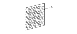
図1は水素吸蔵合金電極に用いるニッケル焼結導電性芯体の製造装置の概略図である。本発明の水素吸蔵合金電極は、金属ニッケル粉末をカルボキシメチルセルロースの1%水溶液を加えたペースト1を円形の凸部が多数形成されたロール2に通し、円形の孔が形成されたシート3とする。これを還元炉4において、1400℃で焼結した後、調厚ロール5により調厚し、直径1.5mmの円形の孔が多数形成された開口率46%の厚さ0.07mmの導電性芯体6を形成した。図2は本発明の水素吸蔵合金電極に用いるニッケル焼結導電性芯体の斜視図である。この導電性芯体の両面に、増粘剤であるカルボキシメチルセルロースの1%水溶液を水素吸蔵合金に加えたペーストを所定量を塗布して、乾燥後プレス加工を行い、40mm(縦)×30mm(横)×0.55mm(厚)の本発明の水素吸蔵合金電極とした。
【0011】
また、比較のため、従来の鉄にニッケルメッキを施した厚さ0.1mm、直径1.5mmの円形の孔が多数形成された、開口率が46%のパンチングメタルの導電性芯体についても同様に40mm(縦)×30mm(横)×0.55mm(厚)の水素吸蔵合金電極を作製した。
【0012】
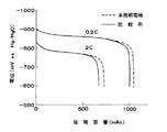
これらの水素吸蔵合金電極の高率放電特性を調べるために、対極としてペースト式ニッケル電極を用い、セパレータを介して前記水素吸蔵合金電極とニッケル電極を配置し、開放型電池を構成した。これに、6.8Nの水酸化カリウム水溶液からなる電解液を注液した。この電極を0.1C率で120%まで充電を行い、0.2C率と2C率で水銀/酸化水銀参照電極に対して−600mVまで放電を行った。
【0013】
図3は各電極の0.2C率と2C率の放電特性を示した図である。本発明電極は比較例に比べ、同寸法の電極であるにもかかわらず、放電電圧が低下することなく、高容量であることが分かる。
【0014】
【発明の効果】
上述のように、本発明は金属ニッケル粉末または金属ニッケル繊維をシート状に焼結して形成した導電性芯体を用いているため薄くても導電性に優れ且つ安価に製造でき、この導電性芯体に水素吸蔵合金を主体とするペーストを塗布した水素吸蔵合金電極は、高率放電特性に優れ、高エネルギー密度の電極を安価に提供できるので、その工業的価値は大である。
【図面の簡単な説明】
【図1】本発明の水素吸蔵合金電極に用いるニッケル焼結導電性芯体の製造装置の概略図である。
【図2】本発明の水素吸蔵合金電極に用いるニッケル焼結導電性芯体の斜視図である。
【図3】本発明と比較例の放電特性を示す図である。
【符号の説明】
1 ペースト
2 ロール
3 シート
4 還元炉
5 調厚ロール
6 導電性芯体[0001]
BACKGROUND OF THE INVENTION
The present invention relates to a hydrogen storage alloy electrode using a hydrogen storage alloy that reversibly stores and releases hydrogen, and is used for a nickel-hydrogen secondary battery and the like.
[0002]
[Prior art]
In recent years, the use of electric vehicles has been taken up as one of the methods for preventing the progress of air pollution by gasoline engine vehicles and the like. In particular, in the United States, a bill stipulating that 10% of the sales volume of gasoline engine vehicles in California is required to be electric vehicles has been passed, and similar bills have been adopted in other states. Expectations for are increasing. Since this electric vehicle is required to have performance equivalent to that of a gasoline engine vehicle, the performance of the power source for the electric vehicle that greatly affects the performance is regarded as very important. The following seven items are listed as main basic performance required for the electric vehicle and its power supply.
(1) One charging mileage is long (energy density is high)
(2) Excellent acceleration and climbing performance (Excellent power density and high rate discharge characteristics)
(3) Can be used in various climatic environments (excellent temperature characteristics)
(4) Less repairs such as battery replacement (long cycle life)
(5) Do not pollute the environment (do not contain harmful substances)
(6) The price should be usable by general users (low cost)
(7) Be safe (high safety)
Currently, various batteries are being investigated as power sources for electric vehicles. However, nickel-metal hydride batteries using a hydrogen storage electrode as the negative electrode have a high energy density, a long cycle life, no harmful substances, and safety. From the standpoint of safety, it is attracting attention as the most promising candidate for electric vehicle power sources.
[0003]
This nickel metal hydride battery mainly uses a hydrogen storage alloy electrode obtained by applying a paste mainly composed of a hydrogen storage alloy to a punching metal conductive core obtained by nickel plating on iron.
[0004]
[Problems to be solved by the invention]
Punching metal in which nickel is plated on iron accounts for 6 to 13% of the volume of the hydrogen storage alloy electrode, restricts the amount of the hydrogen storage alloy as a reactant, and hinders high energy density. . When a conventional punching metal having a thickness of 0.06 to 0.10 mm and an aperture ratio of 31 to 46% is used to produce an electrode plate having a thickness of 0.55 mm, the volume occupied by the hydrogen storage alloy electrode of the conductive core is 6 to It accounts for 13%. If the thickness of the conductive core is reduced, the occupation ratio is reduced, and the hydrogen storage alloy is applied accordingly, the energy density increases. However, if the thickness is reduced, the resistance of the conductive core increases, so that the power density and high-rate discharge performance required for an electric vehicle are reduced, and acceleration and climbing performance are deteriorated. In order to prevent this, a nickel foil or the like having excellent electrical conductivity may be used. However, in order to make a thin foil, there is a drawback that the cost increases because the number of rolling increases.
[0005]
The present invention has been made in view of the above problems. By using a conductive core that is thin and excellent in conductivity and inexpensive, a hydrogen storage alloy electrode that has high energy density and excellent high-rate discharge performance can be obtained at low cost. It is to provide.
[0006]
[Means for Solving the Problems]
To achieve the above object, the hydrogen storage alloy electrode of the present invention, the metallic nickel powder powder paste is formed by sintering the sheet, and, to the conductive core which circular holes are formed a large number of hydrogen It is an electrode to which a paste mainly composed of a storage alloy is applied.
[0007]
DETAILED DESCRIPTION OF THE INVENTION
The metallic nickel powder powder, after a paste with a thickening agent, passed through rolls circular protrusions are formed a large number, and sheet-like circular hole is formed. This is sintered in a reducing atmosphere to obtain a conductive core. Incidentally, without the metallic nickel powder powder and paste, the metallic nickel powder powder directly formed into a sheet may be sintered.
[0008]
This conductive core does not require many rolling processes, and has the advantage that the manufacturing process is simplified and the cost is reduced. Moreover, when it uses as a conductive core of a hydrogen storage alloy electrode, a high capacity | capacitance electrode can be obtained, maintaining the conventional output.
[0009]
【Example】
Embodiments of the present invention will be described below with reference to the drawings.
[0010]
FIG. 1 is a schematic view of an apparatus for producing a nickel sintered conductive core used for a hydrogen storage alloy electrode. The hydrogen storage alloy electrode of the present invention is a
[0011]
Also, for comparison, a punching metal conductive core having an aperture ratio of 46% in which a number of circular holes having a thickness of 0.1 mm and a diameter of 1.5 mm formed by nickel plating on iron are formed. Similarly, a hydrogen storage alloy electrode of 40 mm (length) × 30 mm (width) × 0.55 mm (thickness) was produced.
[0012]
In order to investigate the high rate discharge characteristics of these hydrogen storage alloy electrodes, a paste-type nickel electrode was used as a counter electrode, and the hydrogen storage alloy electrode and the nickel electrode were disposed via a separator to constitute an open type battery. An electrolytic solution composed of a 6.8N potassium hydroxide aqueous solution was poured into this. This electrode was charged to 120% at a rate of 0.1 C, and discharged to -600 mV with respect to the mercury / mercury oxide reference electrode at rates of 0.2 C and 2 C.
[0013]
FIG. 3 is a diagram showing the discharge characteristics of each electrode at 0.2C rate and 2C rate. It can be seen that the electrode of the present invention has a higher capacity than the comparative example, although the discharge voltage does not decrease despite the fact that the electrode has the same dimensions.
[0014]
【The invention's effect】
As described above, the present invention uses a conductive core formed by sintering metallic nickel powder or metallic nickel fiber into a sheet, so that it is excellent in conductivity even at a thin thickness and can be manufactured at low cost. A hydrogen storage alloy electrode in which a paste mainly composed of a hydrogen storage alloy is applied to the core is excellent in high-rate discharge characteristics, and can provide a high energy density electrode at a low cost, and therefore has a great industrial value.
[Brief description of the drawings]
FIG. 1 is a schematic view of an apparatus for producing a nickel sintered conductive core used for a hydrogen storage alloy electrode of the present invention.
FIG. 2 is a perspective view of a nickel sintered conductive core used for the hydrogen storage alloy electrode of the present invention.
FIG. 3 is a graph showing discharge characteristics of the present invention and a comparative example.
[Explanation of symbols]
1
Claims (1)
Priority Applications (1)
| Application Number | Priority Date | Filing Date | Title |
|---|---|---|---|
| JP15463597A JP3734117B2 (en) | 1997-06-12 | 1997-06-12 | Hydrogen storage alloy electrode |
Applications Claiming Priority (1)
| Application Number | Priority Date | Filing Date | Title |
|---|---|---|---|
| JP15463597A JP3734117B2 (en) | 1997-06-12 | 1997-06-12 | Hydrogen storage alloy electrode |
Publications (2)
| Publication Number | Publication Date |
|---|---|
| JPH113702A JPH113702A (en) | 1999-01-06 |
| JP3734117B2 true JP3734117B2 (en) | 2006-01-11 |
Family
ID=15588520
Family Applications (1)
| Application Number | Title | Priority Date | Filing Date |
|---|---|---|---|
| JP15463597A Expired - Fee Related JP3734117B2 (en) | 1997-06-12 | 1997-06-12 | Hydrogen storage alloy electrode |
Country Status (1)
| Country | Link |
|---|---|
| JP (1) | JP3734117B2 (en) |
Families Citing this family (2)
| Publication number | Priority date | Publication date | Assignee | Title |
|---|---|---|---|---|
| KR100404934B1 (en) * | 2001-11-30 | 2003-11-07 | 에너그린(주) | Nickel/metal hydryde secondary battery |
| AU2011214119B2 (en) | 2010-02-09 | 2014-05-01 | Bae Systems Plc | Component including a rechargeable battery |
-
1997
- 1997-06-12 JP JP15463597A patent/JP3734117B2/en not_active Expired - Fee Related
Also Published As
| Publication number | Publication date |
|---|---|
| JPH113702A (en) | 1999-01-06 |
Similar Documents
| Publication | Publication Date | Title |
|---|---|---|
| US5393616A (en) | Metal hydride electrode | |
| JP2018160387A (en) | Alkaline battery | |
| KR101550326B1 (en) | Positive electrode for alkaline storage battery, production method for same, and alkaline storage battery | |
| CN108963241B (en) | Battery, battery pack and uninterruptible power supply | |
| JP3734117B2 (en) | Hydrogen storage alloy electrode | |
| CN103427119B (en) | Battery with a battery cell | |
| CN113793972B (en) | Battery and preparation method thereof | |
| CN105428607A (en) | Nickel-hydrogen secondary battery and manufacturing method thereof | |
| JP2002343366A (en) | Electrode plate for alkaline storage battery and alkaline battery using same | |
| CN204102994U (en) | Nickel-hydrogen secondary cell | |
| JP2989877B2 (en) | Nickel hydride rechargeable battery | |
| JPH1167264A (en) | Manufacture of nickel-hydrogen storage battery | |
| JP3761763B2 (en) | Hydrogen storage alloy electrode, battery using the same, and manufacturing method thereof | |
| JP3182790B2 (en) | Hydrogen storage alloy electrode and method for producing the same | |
| JPH0729569A (en) | Manufacture of hydrogen storage alloy electrode | |
| JPH06150923A (en) | Manufacture of hydrogen storage alloy electrode for sealed battery | |
| JP3092262B2 (en) | Manufacturing method of hydrogen storage alloy electrode | |
| JPH0513077A (en) | Manufacture of hydrogen storage alloy electrode | |
| JP4552238B2 (en) | Method for producing hydrogen storage alloy electrode | |
| JP2932711B2 (en) | Manufacturing method of hydrogen storage alloy electrode for alkaline battery | |
| JPH05258750A (en) | Manufacture of hydrogen storage alloy electrode | |
| JP3136688B2 (en) | Nickel-hydrogen storage battery | |
| JPS62223990A (en) | Sealed storage battery using hydrogen storage alloy electrode | |
| JPH10340720A (en) | Hydrogen storage alloy electrode and manufacture of hydrogen storage alloy electrode | |
| JPH04264362A (en) | Hydrogen storage alloy electrode |
Legal Events
| Date | Code | Title | Description |
|---|---|---|---|
| A521 | Written amendment |
Free format text: JAPANESE INTERMEDIATE CODE: A523 Effective date: 20040302 |
|
| A621 | Written request for application examination |
Free format text: JAPANESE INTERMEDIATE CODE: A621 Effective date: 20040412 |
|
| A977 | Report on retrieval |
Free format text: JAPANESE INTERMEDIATE CODE: A971007 Effective date: 20050411 |
|
| A131 | Notification of reasons for refusal |
Free format text: JAPANESE INTERMEDIATE CODE: A131 Effective date: 20050629 |
|
| A521 | Written amendment |
Free format text: JAPANESE INTERMEDIATE CODE: A523 Effective date: 20050823 |
|
| TRDD | Decision of grant or rejection written | ||
| A01 | Written decision to grant a patent or to grant a registration (utility model) |
Free format text: JAPANESE INTERMEDIATE CODE: A01 Effective date: 20050930 |
|
| A61 | First payment of annual fees (during grant procedure) |
Free format text: JAPANESE INTERMEDIATE CODE: A61 Effective date: 20051013 |
|
| R150 | Certificate of patent or registration of utility model |
Free format text: JAPANESE INTERMEDIATE CODE: R150 |
|
| S111 | Request for change of ownership or part of ownership |
Free format text: JAPANESE INTERMEDIATE CODE: R313111 |
|
| R350 | Written notification of registration of transfer |
Free format text: JAPANESE INTERMEDIATE CODE: R350 |
|
| FPAY | Renewal fee payment (event date is renewal date of database) |
Free format text: PAYMENT UNTIL: 20081028 Year of fee payment: 3 |
|
| S111 | Request for change of ownership or part of ownership |
Free format text: JAPANESE INTERMEDIATE CODE: R313113 |
|
| FPAY | Renewal fee payment (event date is renewal date of database) |
Free format text: PAYMENT UNTIL: 20081028 Year of fee payment: 3 |
|
| R371 | Transfer withdrawn |
Free format text: JAPANESE INTERMEDIATE CODE: R371 |
|
| FPAY | Renewal fee payment (event date is renewal date of database) |
Free format text: PAYMENT UNTIL: 20081028 Year of fee payment: 3 |
|
| S111 | Request for change of ownership or part of ownership |
Free format text: JAPANESE INTERMEDIATE CODE: R313113 Free format text: JAPANESE INTERMEDIATE CODE: R313111 |
|
| FPAY | Renewal fee payment (event date is renewal date of database) |
Free format text: PAYMENT UNTIL: 20081028 Year of fee payment: 3 |
|
| R350 | Written notification of registration of transfer |
Free format text: JAPANESE INTERMEDIATE CODE: R350 |
|
| FPAY | Renewal fee payment (event date is renewal date of database) |
Free format text: PAYMENT UNTIL: 20081028 Year of fee payment: 3 |
|
| FPAY | Renewal fee payment (event date is renewal date of database) |
Free format text: PAYMENT UNTIL: 20091028 Year of fee payment: 4 |
|
| FPAY | Renewal fee payment (event date is renewal date of database) |
Free format text: PAYMENT UNTIL: 20091028 Year of fee payment: 4 |
|
| FPAY | Renewal fee payment (event date is renewal date of database) |
Free format text: PAYMENT UNTIL: 20101028 Year of fee payment: 5 |
|
| FPAY | Renewal fee payment (event date is renewal date of database) |
Free format text: PAYMENT UNTIL: 20101028 Year of fee payment: 5 |
|
| S111 | Request for change of ownership or part of ownership |
Free format text: JAPANESE INTERMEDIATE CODE: R313111 |
|
| FPAY | Renewal fee payment (event date is renewal date of database) |
Free format text: PAYMENT UNTIL: 20101028 Year of fee payment: 5 |
|
| R360 | Written notification for declining of transfer of rights |
Free format text: JAPANESE INTERMEDIATE CODE: R360 |
|
| FPAY | Renewal fee payment (event date is renewal date of database) |
Free format text: PAYMENT UNTIL: 20101028 Year of fee payment: 5 |
|
| R360 | Written notification for declining of transfer of rights |
Free format text: JAPANESE INTERMEDIATE CODE: R360 |
|
| R371 | Transfer withdrawn |
Free format text: JAPANESE INTERMEDIATE CODE: R371 |
|
| FPAY | Renewal fee payment (event date is renewal date of database) |
Free format text: PAYMENT UNTIL: 20101028 Year of fee payment: 5 |
|
| S111 | Request for change of ownership or part of ownership |
Free format text: JAPANESE INTERMEDIATE CODE: R313111 |
|
| FPAY | Renewal fee payment (event date is renewal date of database) |
Free format text: PAYMENT UNTIL: 20111028 Year of fee payment: 6 |
|
| R350 | Written notification of registration of transfer |
Free format text: JAPANESE INTERMEDIATE CODE: R350 |
|
| FPAY | Renewal fee payment (event date is renewal date of database) |
Free format text: PAYMENT UNTIL: 20121028 Year of fee payment: 7 |
|
| LAPS | Cancellation because of no payment of annual fees |