JP3731442B2 - Plant operation monitoring apparatus and plant operation monitoring method - Google Patents
Plant operation monitoring apparatus and plant operation monitoring method Download PDFInfo
- Publication number
- JP3731442B2 JP3731442B2 JP2000144575A JP2000144575A JP3731442B2 JP 3731442 B2 JP3731442 B2 JP 3731442B2 JP 2000144575 A JP2000144575 A JP 2000144575A JP 2000144575 A JP2000144575 A JP 2000144575A JP 3731442 B2 JP3731442 B2 JP 3731442B2
- Authority
- JP
- Japan
- Prior art keywords
- screen
- displayed
- trend graph
- plant
- trend
- Prior art date
- Legal status (The legal status is an assumption and is not a legal conclusion. Google has not performed a legal analysis and makes no representation as to the accuracy of the status listed.)
- Expired - Lifetime
Links
Images


Description
【0001】
【発明の属する技術分野】
本発明は、CRT表示装置等のディスプレイ装置にプラント機器のプロセス量のトレンドグラフを表示してプラントの運転監視を行うプラント運転監視装置及びプラント運転監視方法に関する。
【0002】
【従来の技術】
例えば、特開平9−237117 号公報に記載されているように、プラントの運転状態を連続して監視するのにプラント機器のプロセス量のトレンドグラフをディスプレイ装置に表示することが行われている。トレンドグラフは過去から現在に至るプロセス信号の過去の履歴と将来傾向の把握がし易く、かつプラント機器操作によるプロセス信号の応答を容易に把握できる。
【0003】
また、特開平5−88744号公報には、プロセス量をバーグラフとして表示する運転画面と、プロセス量の推移をトレンドグラフとして表示するトレンドグラフ画面を切替可能とすることが記載されている。
【0004】
また、トレンドグラフとプラント機器のプラント量を操作する操作端を操作,監視するための機器操作端画面とをディスプレイ装置に表示させ、トレンドグラフを見ながらプラントを運転操作することが行われている。
【0005】
トレンドグラフと機器操作端画面をディスプレイ装置に同時に表示させるには、次のような方法が知られている。
(1)予め必要な複数個の機器操作端画面をグループ化しておき、機器操作端画面のグループ画面を表示した後に画面表示したボタン操作によりトレンドグラフのウィンドウ画面を重ね合せ表示する。
(2)機器操作端画面のグループ画面とトレンドグラフを統合した画面を呼出して同時に表示する。
(3)ディスプレイ装置に表示されているプラント系統図のプラント機器を指示して機器操作端画面を表示して、当該機器操作端画面に対応するトレンドグラフを表示する。
【0006】
上述の(3)の方法については、例えば特開平8−272436 号公報に記載されている。
【0007】
【発明が解決しようとする課題】
プラントの運転監視を行う際にはディスプレイ装置にプラント機器のプロセス信号のトレンドグラフを表示していることが多い。それも、複数個のプラント機器のプロセス量のトレンドグラフを同時に表示している。ディスプレイ装置に複数個のプラント機器のプロセス量のトレンドグラフを表示してプラントの運転監視を行っている際に、あるプロセス量のトレンドグラフが予定と異なる変化を示し当該プロセス量に係るプラント機器の操作端操作が必要になる場合がある。
【0008】
しかしながら、上記従来の技術では、ディスプレイ装置に表示されている複数個のプラント機器のプロセス量のトレンドグラフと、当該トレンドグラフにおけるプラント機器のプラント信号を操作する機器操作端画面との関連付けがなされていないために当該プロセス量に係るプラント機器の操作端を操作する機器操作端画面を容易かつ迅速に選択して当該プロセス機器の操作端を操作することができない。
【0009】
本発明の目的は、トレンドグラフ表示されているプロセス機器に係る機器操作端画面を容易かつ迅速に選択して、当該プロセス機器の操作端を操作できるプラント運転監視装置及びプラント運転監視方法を提供することにある。
【0010】
【課題を解決するための手段】
上記目的を達成するために本発明では、表示装置の同一画面に表示されている複数個のプラント機器のプロセス量のトレンドグラフの中から任意のトレンドグラフを選択することにより当該トレンドグラフに対応した機器操作端画面を呼出してトレンドグラフと共に前記表示装置に表示してプラント機器を操作できるようにしたものである。
【0011】
また、本発明では、表示装置の同一画面に複数個のトレンドグラフと共に当該トレンドグラフを選択する選択スイッチを表示し、選択スイッチによりトレンドグラフを選択すると当該トレンドグラフに対応した機器操作端画面が表示されるようにしてもよい。
また、表示装置は、タッチ操作可能なタッチスクリーンを備え、タッチスクリーンをタッチ操作して表示装置に表示されている任意のトレンドグラフを選択できるようにしてもよい。
【0012】
なお、機器操作端画面を表示装置に複数個表示してもよく、更には、機器操作端画面をトレンドグラフの一部、或いは、選択スイッチに重ねて表示するものであってもよい。
【0013】
そして、本発明によれば、トレンドグラフを選択することによって当該プロセス量を操作するプラント機器の操作端に係る機器操作端画面を容易かつ迅速に表示し、当該操作端を機器操作端画面を用いて操作することによって、トレンドグラフに対応するプロセス量の調整を行うことができる。その結果として、プラント異常時の対応を容易かつ迅速に行うことができる。
【0014】
【発明の実施の形態】
図1に本発明の一実施例であるプラント運転監視装置の構成を示す。
【0015】
プラント運転監視装置は、例えば、火力プラント,原子力プラント,上下水プラント,化学プラントなどを対象とし、プラントを構成する各プラント機器の運転監視を行うものである。
【0016】
図1において、1は演算処理装置であるプロセス計算機で、詳細については後述する。CRT表示装置2はCRT制御装置3により制御され、プロセス計算機1から与えられる表示情報に基づきプラント系統図やトレンドグラフ等のプラント情報を表示する。CRT表示装置2にはタッチスクリーン4が配設されている。
【0017】
タッチスクリーン4のタッチ位置座標はタッチスクリーン入力制御装置5を介してプロセス計算機1に入力される。操作キー装置6はプラント機器を手動で操作する手動操作信号(開信号,閉信号あるいは増信号,減信号)を入力するもので、複数個の操作キーから構成される。操作キー装置6の手動操作信号は操作キー入力制御装置7を介してプロセス計算機1に入力される。
【0018】
キーボード8は、CRT表示装置2に表示して監視するトレンドグラフ画面番号(画面選択信号)が入力される。キーボード8の画面選択信号はキーボード入力制御装置9を介してプロセス計算機1に入力される。プラント11は複数個のプラント機器の操作端12とプロセス量を検出する複数個のプロセス信号発信器13とから構成される。
【0019】
プロセス計算機1から出力されるプラント機器の制御信号はプロセス入出力制御装置10を介して操作端12に与えられ、また、プロセス信号発信器13で検出したプロセス信号はプロセス入出力制御装置10を介してプロセス計算機1に入力される。
【0020】
図2にプロセス計算機1の詳細な機能ブロック図を示す。
【0021】
図2において、オペレータがキーボード8から入力した画面選択信号はキーボード入力制御装置9を介してキー入力判別部118に入力される。キー入力判別部118は画面選択信号に基づきCRT表示装置2に表示するトレンドグラフ画面を判定し、トレンドグラフの画面編集部103を起動させる。
【0022】
プロセス信号発信器13で検出したプロセス信号は、プロセス入出力制御装置10を介してプロセス信号取込部101に入力される。プロセス信号取込部101はプロセス信号の工学単位変換を行いトレンドグラフ画面編集部103に与える。トレンドグラフ画面編集部103はプロセス信号取込部101のプロセス信号,トレンドグラフ画面情報テーブル102のトレンド画面情報及びトレンド表示項目登録テーブル108のトレンド表示項目情報に基づいてトレンドグラフ画面を編集する。
【0023】
トレンドグラフ画面編集部103で編集作成されたトレンドグラフ画面は、
CRT画面表示部104によって処理されCRT制御装置3を介してCRT表示装置2にトレンドグラフとして表示される。
【0024】
タッチスクリーン4は、オペレータがCRT制御装置3の画面上にタッチすると、そのタッチ操作を検出する。タッチスクリーン4の検出信号はタッチスクリーン入力制御装置5によってCRT画面上のタッチ位置座標に変換され、タッチ位置取込部105に取込まれる。トレンドチャンネル決定部106は、タッチ位置取込部105からのタッチ位置座標をもとにタッチされたトレンドチャンネル番号を決定する。
【0025】
プロセス入力点番号検索部107は、トレンド表示項目登録テーブル108を参照してトレンドチャンネルに登録されているプロセス信号のプロセス入力点番号を検索する。操作端番号検索部109は、プロセス入力点番号検索部107のプロセス入力点番号検索結果をもとに、操作端番号テーブル110を参照してプロセス入力点番号に対応した操作端番号を検索する。
【0026】
機器操作端画面番号検索部111は、操作端番号検索部109の操作端番号検索結果をもとに、機器操作端画面番号登録テーブル112を参照して機器操作端画面番号を検索する。機器操作端画面編集部113は、機器操作端画面番号検索部111の機器操作端番号検索結果をもとに、機器操作端画面情報テーブル114を参照して機器操作端画面を編集する。
【0027】
CRT画面表示部104は、機器操作端画面編集部113で編集作成された機器操作端画面を、CRT制御装置3を介してCRT表示装置2に表示されているトレンドグラフに追加して表示する。
【0028】
操作キー装置6からキー入力されるキー入力信号(制御モード信号と手動操作信号)が操作キー入力制御装置7を介して操作キー信号取込部115に取込まれる。
【0029】
操作キー判別部116は操作キー信号取込部115に取込まれたキー入力信号を判別し制御信号生成部117に制御モード信号と手動操作信号を入力する。
【0030】
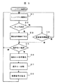
次に、本発明の一実施例であるプラント運転監視装置の動作を図3,図4に示すフローチャートに基づいて説明する。
【0031】
オペレータは監視したいプラント機器のプラント量について、キーボード8のキー操作によりそのトレンドグラフの画面選択信号を入力する。画面選択信号はキーボード入力制御装置9を介してプロセス計算機1のキー入力判別部118に入力される。キー入力判別部118はトレンドグラフ画面を判定しトレンドグラフ画面編集部103を起動させる。
【0032】
トレンドグラフ画面編集部103はプロセス信号取込部101からのプロセス信号,トレンドグラフ画面情報テーブル102のトレンド画面情報およびトレンド表示項目登録テーブル108のトレンド表示項目情報に基づいてトレンドグラフ画面を編集する。トレンドグラフ画面編集部103で編集作成されたトレンドグラフ画面をCRT画面表示部104によってCRT制御装置3を介してCRT表示装置2に表示する。プロセス計算機1はこのようにしてCRT表示装置2にトレンドグラフ画面を表示して図3に示すステップS1の処理を終了する。
【0033】
なお、CRT表示装置2にトレンドグラフ画面が表示されているとき、キーボード8より新たな画面選択信号が入力された場合、トレンドグラフ画面情報テーブル102に記憶されているデータに加えて新たな入力データが記憶され、CRT表示装置2に新たな入力データに基づくトレンドグラフ画面が追加される、或いは、トレンドグラフ画面情報テーブル102に記憶されているデータに換えて新たな入力データが記憶され、CRT表示装置2に新たな入力データに基づくトレンドグラフ画面が表示される。
【0034】
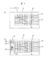
プロセス計算機1のステップS1の処理によって、CRT表示装置2には例えば図5(a)に示すトレンドグラフ画面21が表示される。図5(a)はNo.1〜No.4のトレンドグラフが表示されている例を示している。
【0035】
トレンドグラフ画面21にはトレンドチャンネル番号1〜6を付した6個の選択スイッチ22が表示される。また、選択スイッチ22の夫々の右側にプロセス信号名称23が表示される。プロセス信号名称23はプロセス入力点番号によって表示することもできる。また、選択スイッチ22には、No.1〜No.4のトレンドグラフが夫々異なる色で表示する場合にはトレンドチャンネル番号1〜6でなく対応するトレンドグラフの色を付すこともできる。
【0036】
このように、CRT表示装置2に図5(a)に示すトレンドグラフ画面21を表示してプラントの運転監視を行っているときにトレンドグラフ2のプロセス量を操作する必要が生じたとする。オペレータはトレンドグラフ画面21に表示されているトレンドチャンネル番号「2」の選択スイッチ22にタッチする。選択スイッチ22へのタッチ操作はタッチスクリーン4により検出される。
【0037】
タッチスクリーン4の検出信号はタッチスクリーン入力制御装置5によって
CRT画面上のタッチ位置座標に変換され、タッチ位置取込部105に取込まれる。プロセス計算機1は図3のステップS2でタッチ選択有りと判断しステップS3の処理に移行する。また、ステップS2でタッチ選択無しと判断した場合にはステップS4の処理に移行する。
【0038】
ステップS3では、まず図4のステップS31においてトレンドチャンネル決定部106がタッチ位置座標をもとにタッチ選択されたトレンドチャンネル番号「2」を決定する。プロセス入力点番号検索部107は、ステップS32においてトレンド表示項目登録テーブル108を参照してトレンドチャンネル番号「2」に対応するプロセス信号のプロセス入力点番号を検索する。
【0039】
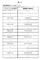
図2に示すトレンド表示項目登録テーブル108には、例えば図7に示すようにトレンドチャンネル番号1〜6とプロセス信号のプロセス入力点番号(例えば、B215,B005等)が格納されている。この場合にはトレンドチャンネル番号「2」に対応するプロセス入力点番号「B005]が検索される。プロセス入力点番号検索部107で検索されたプロセス入力点番号「B005]は操作端番号検索部109に与えられる。
【0040】
図2に示す操作端番号検索部109は、図4に示すステップS33においてプロセス入力点番号に基づき操作端番号テーブル110を参照してプロセス入力点番号に対応した操作端番号を検索する。操作端番号テーブル110には、例えば図8に示すようにプロセス入力点番号と操作端番号(例えば、UM001,FW003など)が格納されている。
【0041】
図8は、図2における操作端番号テーブル110の一例の構成図を示し、機器操作端番号における「UM〜」はユニットマスター操作量、「FW〜」は給水流量操作量、「FF〜」は燃料流量操作量、「AF〜」は空気流量操作量、「ST〜」は蒸気温度操作量、「RT〜」は再熱蒸気温度操作量を意味している。
【0042】
操作端番号検索部109は、例えば、プロセス入力点番号「B005]に対応する機器操作端番号「UM001」を検索し、機器操作端画面番号検索部111に入力する。
【0043】
図2に示す機器操作端画面番号検索部111は、ステップS34において操作端番号に基づき機器操作端画面番号登録テーブル112を参照して機器操作端画面番号を検索する。機器操作端画面番号登録テーブル112には図9に示すように機器操作端番号と機器操作端画面番号が格納されている。機器操作端画面番号は図8に示した操作端番号テーブル110における機器操作端番号にGを付したものである。
【0044】
例えば、機器操作端番号「UM001」が機器操作端画面番号検索部111に入力されると、機器操作端画面番号検索部111はステップS34において機器操作端画面番号「GUM001」を検索する。
【0045】
図2に示す機器操作端画面編集部113は、ステップS35において機器操作端画面番号に基づき機器操作端画面情報テーブル114を参照して機器操作端画面を編集する。CRT画面表示部104は、ステップS36において機器操作端画面編集部113の機器操作端画面編集結果をもとにCRT制御装置3を介してCRT表示装置2に表示されているトレンドグラフ画面21と共に機器操作端画面24を表示する。
【0046】
なお、機器操作端画面24は、画面消去可能に構成されているものであってもよく、例えば、画面消去の指令がプロセス計算機1に入力されることで消去されるもの、或いは、当該トレンドグラフに対応するプロセス機器の操作端の操作・調整が終了したタイミングによって画面消去されるものが挙げられる。
【0047】
また、一つの機器操作端画面24がCRT表示装置2に表示されているとき、別のトレンドグラフに対応する機器操作端画面24の表示指令がプロセス計算機1に入力された場合、後の表示指令に基づく機器操作端画面24を先に表示されている機器操作端画面24に置き換えるようにしてもよい。或いは、図10または図13に示すように両方の機器操作端画面24を表示してもよい。
【0048】
このように、プロセス計算機1は図3に示すステップS3の処理によって、図5(b)に示すようにCRT表示装置2に表示されているトレンドグラフ画面21にトレンドグラフ2のプロセス量を操作するための機器操作端画面24を追加表示する。
【0049】
機器操作端画面24において、241は操作量のマーカ表示、242はプロセス量の棒グラフ表示を示す。また、243は操作量のディジタル表示、或いは、数値表示、244はプロセス量のディジタル量表示、或いは、数値表示を示す。
【0050】
一方、図3におけるステップS2でタッチ選択無しと判断した場合には、タッチ位置取込部105でステップS4の処理を実行する。ステップS4ではCRT表示装置2に機器操作端画面24が既に表示されているかを判断して、表示有りの場合にはステップS5の処理を実行し、表示無しの場合にはステップS1の処理に戻る。
【0051】
プロセス計算機1の図3に示すステップS1〜ステップS3の処理によって
CRT表示装置2に図5(b)に示す機器操作端画面24が表示されると、No.2のトレンドグラフのプロセス量の操作は次のようにして行われる。
【0052】
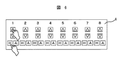
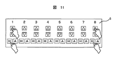
オペレータは図2に示す操作キー装置6のキー操作を行い手動で操作信号を加える。操作キー装置6のキー配置の一例を図6に示す。
【0053】
図6は、操作キー装置のキー配置の一例を示し、CRT表示装置2の画面に一度に表示できる最大数の機器操作端画面24に対応してなり、図6はトレンドグラフNo.1〜8の8組の操作キーグループから成り、各グループにおいて操作キー「△」は「開」(または「増」),「▽」は「閉」(または「減」)操作用のキー,操作キー「H」および「A」はそれぞれ制御モード切替えのための「手動選択」および「自動選択」キーを示す。プラントをプロセス信号発信器13からの信号を元にして計算した制御信号で自動制御する運転では、モード切替操作キー「A」によって運転モードが「自動」モードに切替えられている。この状態からプラントをオペレータの操作信号で手動制御する場合は、モード切替操作キー「H」を操作して「手動」モードに切替えた後、「△」または「▽」キーを操作すると、図1に示す操作キー入力制御装置7を介して「開」(または「増」)操作信号、または「閉」(または「減」)操作信号が計算機1に入力される。
【0054】
さて、上述したように、CRT表示装置2に図5(b)に示す機器操作端画面24が表示され、この機器操作端画面24に対応するのが操作キー装置6の1番目の操作キーグループであるとする。1番目の操作キーグループの制御モード切替えキーのうち「H」キーが押されると、制御モード信号が操作キー入力制御装置7を介してプロセス計算機1の操作キー信号取込部115に取込まれる。プロセス計算機1は図3のステップS5においてキー操作有りと判断し、ステップS6で操作キー信号取込部115の制御モード信号取込みを実行する。
【0055】
操作キー判別部116がステップS7で「H」キーが押されたものと判別すると、制御信号生成部117によりステップS8で制御モードが手動モードに切替えられる。
【0056】
この状態で1番目の操作キーグループの「△」操作キーまたは「▽」操作キーを押し手動操作信号を入力すると、操作キー入力制御装置7を介して制御モード信号と同様にステップS6で操作キー信号取込部115に取込まれる。
【0057】
操作キー判別部116はステップS7で手動操作信号が「開」(または「増」)か「閉」(または「減」)かの操作判別と操作タイミング(操作開始のタイミング,操作継続時間など)の判別処理を実行する。制御信号生成部117はステップS8において操作キー判別部116の判別結果に基づいて制御信号を生成する。制御信号生成部117の制御信号はプロセス計算機1の出力となり、プロセス入出力制御装置10を介して対応したプラント機器の操作端12が操作・制御される。
【0058】
このように操作キー装置6のキー操作によって手動操作している際に、操作端画面情報テーブル114に登録されたプロセス信号がプロセス信号発信器13からプロセス入出力制御装置10を介して取込まれ、CRT表示装置2に表示されている機器操作端画面24は更新表示される。具体的には、プラント機器の操作端12に関連したプロセス量の棒グラフ表示242と操作量のマーカ表示241、及び操作量のディジタル表示243,プロセス量のディジタル表示244がそれぞれ更新表示される。
【0059】
このように、オペレータは、トレンドグラフ画面21と機器操作端画面24の表示を見ながら該当するプラント機器の操作端12を手動操作することが出来る。
【0060】
以上のようにしてトレンドグラフに係るプロセス量を手動操作するのであるが、トレンドグラフを選択することにより、当該プロセス量を操作・調節するプラント機器に係る操作端12の機器操作端画面をCRT表示装置に容易かつ迅速に選択し表示し、当該プロセス量の調整を操作できる。その結果として、プラント異常時の対応を容易かつ迅速に行うことができる。
【0061】
なお、上述の実施例はトレンドグラフ画面21に1つの機器操作端画面24を表示しているが、図10(a)に示すCRT表示装置2の表示画面に図10(b)のように2つの機器操作端画面24A,24Bを表示して2つのトレンドグラフに係るプロセス量を操作するようにすることもできることは明らかなことである。この場合、2つの機器操作端画面24A,24Bにおける操作キー装置6は例えば図11に示すように1番目と8番目の操作キーグループに対応し、それを操作することになる。
【0062】
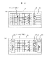
また、長期間のプラント機器のプラント量を監視する場合、図12(a)に示すようにCRT表示装置2の表示画面の全体にわたってトレンドグラフ画面21を表示させることがある。この場合、図12(b)に示すようにトレンドグラフ画面21に重ねて操作機器画面24を表示するようにしてもよい。この場合、トレンドグラフ画面の右側に至るにつれて現在に近づいているので、トレンドグラフ画面21の左端部に重ねて操作機器画面24を表示してもよい。或いは、トレンドグラフの特異点を避けるように操作機器画面24を表示してもよい。
【0063】
操作機器画面24はCRT表示装置2の表示画面の任意の位置に表示することができ、また、一旦表示した位置から別の位置へ移動することもできる。
【0064】
図13(a)は、CRT表示装置2の表示画面の全体にわたってトレンドグラフ画面21を表示させ、図13(b)に示すように複数個の操作機器画面24A,24Bを表示するようにしたものである。操作機器画面24Aをトレンドグラフ画面21の左端部に重ねて操作機器画面24を表示し、操作機器画面24Bをプロセス信号名称23に重ねて表示している例である。
【0065】
また、トレンドグラフの選択をタッチスクリーン4で行っているが、マウスを用いてトレンドグラフをマウスカーソルにより選択しても同様の効果を得ることが出来る。
【0066】
更に、操作キー装置6の操作端操作入力手段(操作キーボタン画面)を機器操作端画面24上に設け、マウスカーソルで操作してもよいことは勿論のことである。
【0067】
【発明の効果】
以上説明したように本発明によれば、トレンドグラフ(プロセス信号)を選択するだけで当該プロセス量を調節するプラント機器の操作端に係る機器操作端画面をディスプレイ装置に容易かつ迅速に表示でき、当該プロセス量の調整を操作できる。その結果として、プラント異常時の対応を容易かつ迅速に行うことができる。
【図面の簡単な説明】
【図1】本発明の一実施例であるプラント運転監視装置の構成である。
【図2】図1のプロセス計算機1の詳細な機能ブロック図である。
【図3】本発明の一実施例であるプラント運転監視装置の動作を説明するためのフローチャートである。
【図4】本発明の一実施例であるプラント運転監視装置の動作を説明するためのフローチャートである。
【図5】(a)(b)は、CRT表示装置の画面表示の一例図である。
【図6】操作キー装置のキー配置の一例図である。
【図7】プロセス入力点番号検索テーブルの一例の構成図である。
【図8】操作端番号検索テーブルの一例の構成図である。
【図9】操作端画面番号検索テーブルの一例の構成図である。
【図10】(a)(b)は、CRT表示装置の画面表示の他の一例図である。
【図11】操作キー装置のキー操作の一例図である。
【図12】(a)(b)は、CRT表示装置の画面表示の他の一例図である。
【図13】(a)(b)は、CRT表示装置の画面表示の他の一例図である。
【符号の説明】
1…プロセス計算機、2…CRT表示装置、3…CRT制御装置、4…タッチスクリーン、5…タッチスクリーン入力制御装置、6…操作キー装置、7…操作キー信号入力装置、8…キーボード、9…キーボード入力制御装置、10…プロセス入出力制御装置、11…プラント、12…操作端、13…プロセス信号発信器。[0001]
BACKGROUND OF THE INVENTION
The present invention relates to a plant operation monitoring apparatus and a plant operation monitoring method for monitoring a plant operation by displaying a trend graph of a process amount of plant equipment on a display device such as a CRT display device.
[0002]
[Prior art]
For example, as described in JP-A-9-237117, a trend graph of the process amount of plant equipment is displayed on a display device in order to continuously monitor the operation state of the plant. The trend graph makes it easy to grasp past histories and future trends of process signals from the past to the present, and can easily grasp the response of process signals caused by plant equipment operations.
[0003]
Japanese Patent Application Laid-Open No. 5-88744 describes that an operation screen that displays a process amount as a bar graph and a trend graph screen that displays a transition of the process amount as a trend graph can be switched.
[0004]
In addition, a trend graph and a device operation end screen for operating and monitoring the operation end for operating the plant amount of the plant equipment are displayed on the display device, and the plant is operated while viewing the trend graph. .
[0005]
In order to display the trend graph and the device operation end screen on the display device at the same time, the following methods are known.
(1) A plurality of necessary device operation end screens are grouped in advance, and after displaying the group operation end screen group screen, the trend graph window screen is displayed in a superimposed manner by the button operation displayed on the screen.
(2) Recalling and displaying a screen integrating the group screen and trend graph on the device operation end screen.
(3) The plant equipment in the plant system diagram displayed on the display device is indicated to display the equipment operation end screen, and the trend graph corresponding to the equipment operation end screen is displayed.
[0006]
The above method (3) is described in, for example, Japanese Patent Laid-Open No. 8-272436.
[0007]
[Problems to be solved by the invention]
When performing plant operation monitoring, a trend graph of process signals of plant equipment is often displayed on a display device. It also displays a trend graph of the process amount of multiple plant devices at the same time. When the trend graph of the process quantity of multiple plant equipment is displayed on the display device and the operation of the plant is monitored, the trend graph of a certain process quantity shows a change different from the schedule and the plant equipment related to the process quantity Operation end operation may be required.
[0008]
However, in the above conventional technique, the trend graph of the process amount of the plurality of plant equipment displayed on the display device is associated with the equipment operation end screen for operating the plant signal of the plant equipment in the trend graph. Therefore, the operation end of the process equipment cannot be operated by selecting the equipment operation end screen for operating the operation end of the plant equipment related to the process amount easily and quickly.
[0009]
An object of the present invention is to provide a plant operation monitoring apparatus and a plant operation monitoring method capable of easily and quickly selecting an apparatus operation end screen related to a process apparatus displayed in a trend graph and operating the operation end of the process apparatus. There is.
[0010]
[Means for Solving the Problems]
In order to achieve the above object, in the present invention, an arbitrary trend graph is selected from among the trend graphs of the process quantities of a plurality of plant devices displayed on the same screen of the display device. The device operation end screen is called and displayed on the display device together with the trend graph so that the plant device can be operated.
[0011]
In the present invention, a selection switch for selecting the trend graph is displayed together with a plurality of trend graphs on the same screen of the display device, and when the trend graph is selected by the selection switch, a device operation end screen corresponding to the trend graph is displayed. You may be made to do.
The display device may include a touch screen that can be touch-operated, and may be configured to select an arbitrary trend graph displayed on the display device by touching the touch screen.
[0012]
Note that a plurality of device operation end screens may be displayed on the display device, and further, the device operation end screen may be displayed in a part of the trend graph or over the selection switch.
[0013]
And according to this invention, the equipment operation end screen which concerns on the operation end of the plant equipment which operates the said process amount by selecting a trend graph is displayed easily and rapidly, and the said operation end is used for an equipment operation end screen. The process amount corresponding to the trend graph can be adjusted. As a result, it is possible to easily and quickly cope with a plant abnormality.
[0014]
DETAILED DESCRIPTION OF THE INVENTION
FIG. 1 shows a configuration of a plant operation monitoring apparatus according to an embodiment of the present invention.
[0015]
The plant operation monitoring device targets, for example, a thermal power plant, a nuclear power plant, a water and sewage plant, a chemical plant, and the like, and performs operation monitoring of each plant device constituting the plant.
[0016]
In FIG. 1, 1 is a process computer which is an arithmetic processing unit, and details will be described later. The
[0017]
The touch position coordinates of the
[0018]
A trend graph screen number (screen selection signal) to be displayed and monitored on the
[0019]
A control signal for the plant equipment output from the
[0020]
FIG. 2 shows a detailed functional block diagram of the
[0021]
In FIG. 2, the screen selection signal input from the
[0022]
The process signal detected by the
[0023]
Trend graph screen that was created edited in the trend graph
It is processed by the CRT
[0024]
When the operator touches the screen of the
[0025]
The process input point number search unit 107 searches the process input point number of the process signal registered in the trend channel with reference to the trend display item registration table 108. Based on the process input point number search result of the process input point number search unit 107, the operation terminal
[0026]
The device operation terminal screen number search unit 111 searches the device operation terminal screen number by referring to the device operation terminal screen number registration table 112 based on the operation terminal number search result of the operation terminal
[0027]
The CRT
[0028]
Key input signals (control mode signal and manual operation signal) key-input from the operation
[0029]
The operation
[0030]
Next, the operation of the plant operation monitoring apparatus according to an embodiment of the present invention will be described based on the flowcharts shown in FIGS.
[0031]
The operator inputs a screen selection signal of the trend graph by operating the
[0032]
The trend graph
[0033]
When a trend graph screen is displayed on the
[0034]
By the process of step S1 of the
[0035]
On the
[0036]
As described above, when the
[0037]
The detection signal of the
[0038]
In step S3, first, the trend
[0039]
The trend display item registration table 108 shown in FIG. 2 stores, for example,
[0040]
The operation terminal
[0041]
FIG. 8 shows a configuration diagram of an example of the operation end number table 110 in FIG. 2. In the device operation end numbers, “UM˜” is a unit master operation amount, “FW˜” is a feed water flow amount, and “FF˜” Fuel flow manipulated variable, “AF˜” means air flow manipulated variable, “ST˜” means steam temperature manipulated variable, and “RT˜” means reheat steam temperature manipulated variable.
[0042]
For example, the operation terminal
[0043]
The device operation terminal screen number search unit 111 shown in FIG. 2 searches the device operation terminal screen number by referring to the device operation terminal screen number registration table 112 based on the operation terminal number in step S34. The device operation end screen number registration table 112 stores device operation end numbers and device operation end screen numbers as shown in FIG. The device operation terminal screen number is obtained by adding G to the device operation terminal number in the operation terminal number table 110 shown in FIG.
[0044]
For example, when the device operation terminal number “UM001” is input to the device operation terminal screen number search unit 111, the device operation terminal screen number search unit 111 searches for the device operation terminal screen number “GUM001” in step S34.
[0045]
The device operation end screen editing unit 113 shown in FIG. 2 edits the device operation end screen with reference to the device operation end screen information table 114 based on the device operation end screen number in step S35. The CRT
[0046]
The device
[0047]
Further, when one device
[0048]
As described above, the
[0049]
On the device
[0050]
On the other hand, if it is determined in step S2 in FIG. 3 that there is no touch selection, the touch
[0051]
When the device
[0052]
The operator manually operates the operation
[0053]
6 shows an example of the key arrangement of the operation key device, corresponding to the maximum number of device operation end screens 24 that can be displayed on the screen of the
[0054]
As described above, the device
[0055]
When the operation
[0056]
In this state, when the “△” operation key or “▽” operation key of the first operation key group is pressed to input a manual operation signal, the operation key is operated in step S6 via the operation key
[0057]
In step S7, the operation
[0058]
As described above, when the manual operation is performed by the key operation of the operation
[0059]
In this way, the operator can manually operate the
[0060]
As described above, the process amount related to the trend graph is manually operated. By selecting the trend graph, the device operation end screen of the
[0061]
In the above-described embodiment, one device
[0062]
Moreover, when monitoring the plant quantity of plant equipment for a long time, the
[0063]
The
[0064]
FIG. 13 (a) displays the
[0065]
Although the trend graph is selected on the
[0066]
Furthermore, it goes without saying that an operation end operation input means (operation key button screen) of the operation
[0067]
【The invention's effect】
As described above, according to the present invention, the device operation end screen related to the operation end of the plant device that adjusts the process amount by simply selecting a trend graph (process signal) can be easily and quickly displayed on the display device. The process quantity adjustment can be manipulated. As a result, it is possible to easily and quickly cope with a plant abnormality.
[Brief description of the drawings]
FIG. 1 is a configuration of a plant operation monitoring apparatus according to an embodiment of the present invention.
FIG. 2 is a detailed functional block diagram of the
FIG. 3 is a flowchart for explaining the operation of the plant operation monitoring apparatus according to the embodiment of the present invention.
FIG. 4 is a flowchart for explaining the operation of the plant operation monitoring apparatus according to the embodiment of the present invention.
FIGS. 5A and 5B are examples of a screen display of a CRT display device. FIGS.
FIG. 6 is an example of a key arrangement of the operation key device.
FIG. 7 is a configuration diagram of an example of a process input point number search table.
FIG. 8 is a configuration diagram of an example of an operation end number search table.
FIG. 9 is a configuration diagram of an example of an operation end screen number search table.
FIGS. 10A and 10B are other examples of screen display of a CRT display device. FIGS.
FIG. 11 is a diagram illustrating an example of key operation of the operation key device.
FIGS. 12A and 12B are other examples of screen display of the CRT display device.
FIGS. 13A and 13B are other examples of screen display of the CRT display device. FIGS.
[Explanation of symbols]
DESCRIPTION OF
Claims (3)
複数個のプロセス量のトレンドグラフを表示装置の同一画面に表示し、前記表示装置に表示されている任意のトレンドグラフを複数個選択した場合、当該複数個のトレンドグラフのプロセス量を操作するための各操作端画面が前記選択した複数個のトレンドグラフと共に前記表示装置に表示され、前記各操作端画面に対応した操作信号を入力して前記プロセス量を制御することを特徴とするプラント運転監視方法。A plant operation monitoring method for capturing a state signal including a process amount of plant equipment and monitoring operation of the plant,
When a plurality of trend graphs of process quantities are displayed on the same screen of a display device and a plurality of arbitrary trend graphs displayed on the display device are selected, the process quantities of the plurality of trend graphs are manipulated Each operation end screen is displayed on the display device together with the selected plurality of trend graphs, and an operation signal corresponding to each operation end screen is input to control the process amount. Method.
複数個のプロセス量のトレンドグラフ共に任意のトレンドグラフを選択できる選択スイッチを表示装置の同一画面に表示し、前記選択スイッチにより任意のトレンドグラフを選択すると当該トレンドグラフのプロセス量を操作するための操作端画面が前記トレンドグラフと共に前記表示装置に表示され、前記操作端画面に対応した操作信号を入力して前記プロセス量を制御するようにし、前記複数個のプロセス量のトレンドグラフは異なる色で表示され、任意のトレンドグラフを選択する選択スイッチは選択するトレンドグラフと同じ色で表示されることを特徴とするプラント運転監視方法。A plant operation monitoring method for capturing a state signal including a process amount of plant equipment and monitoring operation of the plant,
A selection switch capable of selecting an arbitrary trend graph is displayed on the same screen of the display device together with a plurality of process amount trend graphs. When an arbitrary trend graph is selected by the selection switch, the process amount of the trend graph is controlled. An operation end screen is displayed on the display device together with the trend graph, and an operation signal corresponding to the operation end screen is input to control the process amount. The trend graphs of the plurality of process amounts are different colors. A plant operation monitoring method, wherein a selection switch that is displayed and selects an arbitrary trend graph is displayed in the same color as the selected trend graph.
Priority Applications (1)
| Application Number | Priority Date | Filing Date | Title |
|---|---|---|---|
| JP2000144575A JP3731442B2 (en) | 1999-05-21 | 2000-05-12 | Plant operation monitoring apparatus and plant operation monitoring method |
Applications Claiming Priority (3)
| Application Number | Priority Date | Filing Date | Title |
|---|---|---|---|
| JP11-141783 | 1999-05-21 | ||
| JP14178399 | 1999-05-21 | ||
| JP2000144575A JP3731442B2 (en) | 1999-05-21 | 2000-05-12 | Plant operation monitoring apparatus and plant operation monitoring method |
Publications (2)
| Publication Number | Publication Date |
|---|---|
| JP2001042929A JP2001042929A (en) | 2001-02-16 |
| JP3731442B2 true JP3731442B2 (en) | 2006-01-05 |
Family
ID=26473947
Family Applications (1)
| Application Number | Title | Priority Date | Filing Date |
|---|---|---|---|
| JP2000144575A Expired - Lifetime JP3731442B2 (en) | 1999-05-21 | 2000-05-12 | Plant operation monitoring apparatus and plant operation monitoring method |
Country Status (1)
| Country | Link |
|---|---|
| JP (1) | JP3731442B2 (en) |
Families Citing this family (3)
| Publication number | Priority date | Publication date | Assignee | Title |
|---|---|---|---|---|
| JP5259797B2 (en) * | 2011-09-05 | 2013-08-07 | 株式会社東芝 | Learning type process abnormality diagnosis device and operator judgment estimation result collection device |
| JP6103890B2 (en) | 2012-11-08 | 2017-03-29 | 三菱重工業株式会社 | Maintenance monitor device, program thereof and recording medium |
| TWI698728B (en) * | 2018-03-13 | 2020-07-11 | 日商住友重機械工業股份有限公司 | Display device and display method for supporting process control |
Family Cites Families (7)
| Publication number | Priority date | Publication date | Assignee | Title |
|---|---|---|---|---|
| JP2555412B2 (en) * | 1988-04-15 | 1996-11-20 | 株式会社日立製作所 | Display method of process monitoring controller |
| JP2970964B2 (en) * | 1991-09-18 | 1999-11-02 | 株式会社日立製作所 | Monitoring device |
| JP2633741B2 (en) * | 1991-04-11 | 1997-07-23 | アサヒビール株式会社 | Sequence display device |
| JP2680214B2 (en) * | 1991-09-19 | 1997-11-19 | 株式会社日立製作所 | Process monitoring system |
| JPH05323918A (en) * | 1992-05-22 | 1993-12-07 | Hitachi Ltd | Plant supervisor and control device |
| JPH08272436A (en) * | 1995-03-31 | 1996-10-18 | Toshiba Syst Technol Kk | Operation device |
| JP3396559B2 (en) * | 1995-05-23 | 2003-04-14 | 東芝システムテクノロジー株式会社 | Plant monitoring equipment |
-
2000
- 2000-05-12 JP JP2000144575A patent/JP3731442B2/en not_active Expired - Lifetime
Also Published As
| Publication number | Publication date |
|---|---|
| JP2001042929A (en) | 2001-02-16 |
Similar Documents
| Publication | Publication Date | Title |
|---|---|---|
| JP2654283B2 (en) | Icon display method | |
| JP5102362B2 (en) | Plant monitoring and control system | |
| JP6761158B1 (en) | Program creation device, program creation method, and program | |
| JP2009289064A (en) | Monitoring system with human interface function | |
| JPH0454630A (en) | Method and device for controlling item input | |
| JP3731442B2 (en) | Plant operation monitoring apparatus and plant operation monitoring method | |
| JPS61217897A (en) | Process monitor | |
| AU737646B2 (en) | Plant operating and monitoring system, and plant operating and monitoring method | |
| JP2006324707A (en) | Remote control apparatus | |
| JPH06231380A (en) | Process display device | |
| JP2555412B2 (en) | Display method of process monitoring controller | |
| KR101886986B1 (en) | Engineering tool program and engineering tool | |
| JP3984658B2 (en) | Information processing apparatus and method | |
| JPH05323918A (en) | Plant supervisor and control device | |
| JP2011106854A (en) | Measuring instrument | |
| JP3670317B2 (en) | Operation device | |
| JPH07271429A (en) | Method and device for display and system and method for plant control | |
| JP2008293392A (en) | Ladder programming editor | |
| JPH06131136A (en) | Time-changing data display device | |
| JP2786737B2 (en) | Process display device | |
| JP2831505B2 (en) | Molding machine controller | |
| JP2003280733A (en) | Supervisory control system | |
| JP3020637B2 (en) | Process display device | |
| JP3623240B2 (en) | Graph display device | |
| JPH09289690A (en) | Centralized supervisory control system |
Legal Events
| Date | Code | Title | Description |
|---|---|---|---|
| A977 | Report on retrieval |
Free format text: JAPANESE INTERMEDIATE CODE: A971007 Effective date: 20050427 |
|
| A131 | Notification of reasons for refusal |
Free format text: JAPANESE INTERMEDIATE CODE: A131 Effective date: 20050719 |
|
| A521 | Request for written amendment filed |
Free format text: JAPANESE INTERMEDIATE CODE: A523 Effective date: 20050829 |
|
| TRDD | Decision of grant or rejection written | ||
| A01 | Written decision to grant a patent or to grant a registration (utility model) |
Free format text: JAPANESE INTERMEDIATE CODE: A01 Effective date: 20050920 |
|
| A61 | First payment of annual fees (during grant procedure) |
Free format text: JAPANESE INTERMEDIATE CODE: A61 Effective date: 20051003 |
|
| R150 | Certificate of patent or registration of utility model |
Ref document number: 3731442 Country of ref document: JP Free format text: JAPANESE INTERMEDIATE CODE: R150 Free format text: JAPANESE INTERMEDIATE CODE: R150 |
|
| FPAY | Renewal fee payment (event date is renewal date of database) |
Free format text: PAYMENT UNTIL: 20091021 Year of fee payment: 4 |
|
| FPAY | Renewal fee payment (event date is renewal date of database) |
Free format text: PAYMENT UNTIL: 20091021 Year of fee payment: 4 |
|
| FPAY | Renewal fee payment (event date is renewal date of database) |
Free format text: PAYMENT UNTIL: 20101021 Year of fee payment: 5 |
|
| FPAY | Renewal fee payment (event date is renewal date of database) |
Free format text: PAYMENT UNTIL: 20111021 Year of fee payment: 6 |
|
| FPAY | Renewal fee payment (event date is renewal date of database) |
Free format text: PAYMENT UNTIL: 20121021 Year of fee payment: 7 |
|
| FPAY | Renewal fee payment (event date is renewal date of database) |
Free format text: PAYMENT UNTIL: 20121021 Year of fee payment: 7 |
|
| FPAY | Renewal fee payment (event date is renewal date of database) |
Free format text: PAYMENT UNTIL: 20131021 Year of fee payment: 8 |
|
| EXPY | Cancellation because of completion of term |