JP3729190B2 - Liquid jet head and manufacturing method thereof - Google Patents
Liquid jet head and manufacturing method thereof Download PDFInfo
- Publication number
- JP3729190B2 JP3729190B2 JP2003290643A JP2003290643A JP3729190B2 JP 3729190 B2 JP3729190 B2 JP 3729190B2 JP 2003290643 A JP2003290643 A JP 2003290643A JP 2003290643 A JP2003290643 A JP 2003290643A JP 3729190 B2 JP3729190 B2 JP 3729190B2
- Authority
- JP
- Japan
- Prior art keywords
- groove
- recess
- plate
- pressure generating
- partition wall
- Prior art date
- Legal status (The legal status is an assumption and is not a legal conclusion. Google has not performed a legal analysis and makes no representation as to the accuracy of the status listed.)
- Expired - Fee Related
Links
- 239000007788 liquid Substances 0.000 title claims description 53
- 238000004519 manufacturing process Methods 0.000 title claims description 19
- PXHVJJICTQNCMI-UHFFFAOYSA-N Nickel Chemical compound [Ni] PXHVJJICTQNCMI-UHFFFAOYSA-N 0.000 claims abstract description 131
- 238000005192 partition Methods 0.000 claims abstract description 101
- 229910052759 nickel Inorganic materials 0.000 claims abstract description 65
- 239000013078 crystal Substances 0.000 claims abstract description 64
- 238000007789 sealing Methods 0.000 claims abstract description 16
- 238000004891 communication Methods 0.000 claims description 82
- 238000005242 forging Methods 0.000 claims description 63
- 239000000463 material Substances 0.000 claims description 60
- 238000012545 processing Methods 0.000 claims description 31
- 238000000034 method Methods 0.000 claims description 30
- 239000002184 metal Substances 0.000 claims description 18
- 229910052751 metal Inorganic materials 0.000 claims description 18
- 238000005304 joining Methods 0.000 claims description 4
- 230000015572 biosynthetic process Effects 0.000 abstract description 23
- 239000004033 plastic Substances 0.000 description 53
- 238000000465 moulding Methods 0.000 description 38
- 230000008569 process Effects 0.000 description 25
- 239000000758 substrate Substances 0.000 description 18
- 230000001965 increasing effect Effects 0.000 description 15
- 229910001220 stainless steel Inorganic materials 0.000 description 9
- 239000010935 stainless steel Substances 0.000 description 9
- 238000000137 annealing Methods 0.000 description 8
- 238000005096 rolling process Methods 0.000 description 8
- 239000007769 metal material Substances 0.000 description 7
- 229920005989 resin Polymers 0.000 description 7
- 239000011347 resin Substances 0.000 description 7
- XUIMIQQOPSSXEZ-UHFFFAOYSA-N Silicon Chemical compound [Si] XUIMIQQOPSSXEZ-UHFFFAOYSA-N 0.000 description 6
- 238000010438 heat treatment Methods 0.000 description 6
- JEIPFZHSYJVQDO-UHFFFAOYSA-N iron(III) oxide Inorganic materials O=[Fe]O[Fe]=O JEIPFZHSYJVQDO-UHFFFAOYSA-N 0.000 description 6
- 230000002265 prevention Effects 0.000 description 6
- 229910052710 silicon Inorganic materials 0.000 description 6
- 239000010703 silicon Substances 0.000 description 6
- 238000003860 storage Methods 0.000 description 6
- 239000002245 particle Substances 0.000 description 5
- 230000000750 progressive effect Effects 0.000 description 5
- 230000007423 decrease Effects 0.000 description 4
- 230000000149 penetrating effect Effects 0.000 description 4
- 230000002035 prolonged effect Effects 0.000 description 4
- 238000010586 diagram Methods 0.000 description 3
- 230000000694 effects Effects 0.000 description 3
- 238000009429 electrical wiring Methods 0.000 description 3
- 238000005530 etching Methods 0.000 description 3
- NJPPVKZQTLUDBO-UHFFFAOYSA-N novaluron Chemical compound C1=C(Cl)C(OC(F)(F)C(OC(F)(F)F)F)=CC=C1NC(=O)NC(=O)C1=C(F)C=CC=C1F NJPPVKZQTLUDBO-UHFFFAOYSA-N 0.000 description 3
- 238000005498 polishing Methods 0.000 description 3
- 229920001187 thermosetting polymer Polymers 0.000 description 3
- 239000004734 Polyphenylene sulfide Substances 0.000 description 2
- 238000006243 chemical reaction Methods 0.000 description 2
- 239000002131 composite material Substances 0.000 description 2
- 230000008602 contraction Effects 0.000 description 2
- 238000005336 cracking Methods 0.000 description 2
- 238000005553 drilling Methods 0.000 description 2
- 230000002349 favourable effect Effects 0.000 description 2
- 230000006872 improvement Effects 0.000 description 2
- 238000012856 packing Methods 0.000 description 2
- 229920000069 polyphenylene sulfide Polymers 0.000 description 2
- 238000004080 punching Methods 0.000 description 2
- 239000002994 raw material Substances 0.000 description 2
- 238000007790 scraping Methods 0.000 description 2
- 238000007493 shaping process Methods 0.000 description 2
- 239000013077 target material Substances 0.000 description 2
- 239000011800 void material Substances 0.000 description 2
- XLYOFNOQVPJJNP-UHFFFAOYSA-N water Substances O XLYOFNOQVPJJNP-UHFFFAOYSA-N 0.000 description 2
- VYZAMTAEIAYCRO-UHFFFAOYSA-N Chromium Chemical compound [Cr] VYZAMTAEIAYCRO-UHFFFAOYSA-N 0.000 description 1
- 229910001111 Fine metal Inorganic materials 0.000 description 1
- 239000004642 Polyimide Substances 0.000 description 1
- 230000004308 accommodation Effects 0.000 description 1
- 230000001154 acute effect Effects 0.000 description 1
- 238000005452 bending Methods 0.000 description 1
- 230000008859 change Effects 0.000 description 1
- 239000004020 conductor Substances 0.000 description 1
- 230000001276 controlling effect Effects 0.000 description 1
- 238000001816 cooling Methods 0.000 description 1
- 238000007872 degassing Methods 0.000 description 1
- 230000006866 deterioration Effects 0.000 description 1
- 238000009826 distribution Methods 0.000 description 1
- 239000000428 dust Substances 0.000 description 1
- 230000005489 elastic deformation Effects 0.000 description 1
- 230000002708 enhancing effect Effects 0.000 description 1
- 239000003822 epoxy resin Substances 0.000 description 1
- 238000011156 evaluation Methods 0.000 description 1
- 239000012467 final product Substances 0.000 description 1
- 239000003292 glue Substances 0.000 description 1
- 238000000227 grinding Methods 0.000 description 1
- 229910001338 liquidmetal Inorganic materials 0.000 description 1
- 235000013372 meat Nutrition 0.000 description 1
- 238000002844 melting Methods 0.000 description 1
- 230000008018 melting Effects 0.000 description 1
- 230000004048 modification Effects 0.000 description 1
- 238000012986 modification Methods 0.000 description 1
- 238000007747 plating Methods 0.000 description 1
- 229920000647 polyepoxide Polymers 0.000 description 1
- 229920001721 polyimide Polymers 0.000 description 1
- 238000003825 pressing Methods 0.000 description 1
- 239000000047 product Substances 0.000 description 1
- 238000003908 quality control method Methods 0.000 description 1
- 230000001105 regulatory effect Effects 0.000 description 1
- 238000005476 soldering Methods 0.000 description 1
- 238000000638 solvent extraction Methods 0.000 description 1
- -1 strip plate Substances 0.000 description 1
- 239000000126 substance Substances 0.000 description 1
Images


Classifications
-
- B—PERFORMING OPERATIONS; TRANSPORTING
- B41—PRINTING; LINING MACHINES; TYPEWRITERS; STAMPS
- B41J—TYPEWRITERS; SELECTIVE PRINTING MECHANISMS, i.e. MECHANISMS PRINTING OTHERWISE THAN FROM A FORME; CORRECTION OF TYPOGRAPHICAL ERRORS
- B41J2/00—Typewriters or selective printing mechanisms characterised by the printing or marking process for which they are designed
- B41J2/005—Typewriters or selective printing mechanisms characterised by the printing or marking process for which they are designed characterised by bringing liquid or particles selectively into contact with a printing material
- B41J2/01—Ink jet
- B41J2/135—Nozzles
- B41J2/16—Production of nozzles
- B41J2/1621—Manufacturing processes
- B41J2/1637—Manufacturing processes molding
-
- B—PERFORMING OPERATIONS; TRANSPORTING
- B41—PRINTING; LINING MACHINES; TYPEWRITERS; STAMPS
- B41J—TYPEWRITERS; SELECTIVE PRINTING MECHANISMS, i.e. MECHANISMS PRINTING OTHERWISE THAN FROM A FORME; CORRECTION OF TYPOGRAPHICAL ERRORS
- B41J2/00—Typewriters or selective printing mechanisms characterised by the printing or marking process for which they are designed
- B41J2/005—Typewriters or selective printing mechanisms characterised by the printing or marking process for which they are designed characterised by bringing liquid or particles selectively into contact with a printing material
- B41J2/01—Ink jet
- B41J2/135—Nozzles
- B41J2/14—Structure thereof only for on-demand ink jet heads
- B41J2/14016—Structure of bubble jet print heads
-
- B—PERFORMING OPERATIONS; TRANSPORTING
- B41—PRINTING; LINING MACHINES; TYPEWRITERS; STAMPS
- B41J—TYPEWRITERS; SELECTIVE PRINTING MECHANISMS, i.e. MECHANISMS PRINTING OTHERWISE THAN FROM A FORME; CORRECTION OF TYPOGRAPHICAL ERRORS
- B41J2/00—Typewriters or selective printing mechanisms characterised by the printing or marking process for which they are designed
- B41J2/005—Typewriters or selective printing mechanisms characterised by the printing or marking process for which they are designed characterised by bringing liquid or particles selectively into contact with a printing material
- B41J2/01—Ink jet
- B41J2/135—Nozzles
- B41J2/14—Structure thereof only for on-demand ink jet heads
- B41J2/14201—Structure of print heads with piezoelectric elements
- B41J2/14274—Structure of print heads with piezoelectric elements of stacked structure type, deformed by compression/extension and disposed on a diaphragm
-
- B—PERFORMING OPERATIONS; TRANSPORTING
- B41—PRINTING; LINING MACHINES; TYPEWRITERS; STAMPS
- B41J—TYPEWRITERS; SELECTIVE PRINTING MECHANISMS, i.e. MECHANISMS PRINTING OTHERWISE THAN FROM A FORME; CORRECTION OF TYPOGRAPHICAL ERRORS
- B41J2/00—Typewriters or selective printing mechanisms characterised by the printing or marking process for which they are designed
- B41J2/005—Typewriters or selective printing mechanisms characterised by the printing or marking process for which they are designed characterised by bringing liquid or particles selectively into contact with a printing material
- B41J2/01—Ink jet
- B41J2/135—Nozzles
- B41J2/16—Production of nozzles
- B41J2/1607—Production of print heads with piezoelectric elements
- B41J2/1612—Production of print heads with piezoelectric elements of stacked structure type, deformed by compression/extension and disposed on a diaphragm
-
- B—PERFORMING OPERATIONS; TRANSPORTING
- B41—PRINTING; LINING MACHINES; TYPEWRITERS; STAMPS
- B41J—TYPEWRITERS; SELECTIVE PRINTING MECHANISMS, i.e. MECHANISMS PRINTING OTHERWISE THAN FROM A FORME; CORRECTION OF TYPOGRAPHICAL ERRORS
- B41J2/00—Typewriters or selective printing mechanisms characterised by the printing or marking process for which they are designed
- B41J2/005—Typewriters or selective printing mechanisms characterised by the printing or marking process for which they are designed characterised by bringing liquid or particles selectively into contact with a printing material
- B41J2/01—Ink jet
- B41J2/135—Nozzles
- B41J2/16—Production of nozzles
- B41J2/1621—Manufacturing processes
- B41J2/1623—Manufacturing processes bonding and adhesion
-
- B—PERFORMING OPERATIONS; TRANSPORTING
- B41—PRINTING; LINING MACHINES; TYPEWRITERS; STAMPS
- B41J—TYPEWRITERS; SELECTIVE PRINTING MECHANISMS, i.e. MECHANISMS PRINTING OTHERWISE THAN FROM A FORME; CORRECTION OF TYPOGRAPHICAL ERRORS
- B41J2/00—Typewriters or selective printing mechanisms characterised by the printing or marking process for which they are designed
- B41J2/005—Typewriters or selective printing mechanisms characterised by the printing or marking process for which they are designed characterised by bringing liquid or particles selectively into contact with a printing material
- B41J2/01—Ink jet
- B41J2/135—Nozzles
- B41J2/16—Production of nozzles
- B41J2/1621—Manufacturing processes
- B41J2/1632—Manufacturing processes machining
Landscapes
- Engineering & Computer Science (AREA)
- Manufacturing & Machinery (AREA)
- Particle Formation And Scattering Control In Inkjet Printers (AREA)
Abstract
Description
本発明は、圧力発生室形成板に鍛造加工が施される液体噴射ヘッドおよびその製造方法
に関するものである。
The present invention relates to a liquid jet head in which a forging process is performed on a pressure generating chamber forming plate and a method for manufacturing the liquid jet head.
鍛造加工は種々な製品分野で活用されているが、例えば、液体噴射ヘッドの圧力発生室
を金属素材に鍛造で成形することが考えられる。上記液体噴射ヘッドは、加圧された液体
をノズル開口から液滴として吐出させるものであり、種々な液体を対象にしたものが知ら
れている。そのなかでも代表的なものとして、インクジェット式記録ヘッドをあげること
ができる。そこで、従来の技術を上記インクジェット式記録ヘッドを例にとって説明する
。
Forging is used in various product fields. For example, it is conceivable to form a pressure generating chamber of a liquid jet head into a metal material by forging. The liquid ejecting head ejects pressurized liquid as droplets from the nozzle opening, and is known for various liquids. Among them, a typical example is an ink jet recording head. Therefore, the prior art will be described by taking the ink jet recording head as an example.
インクジェット式記録ヘッド(以下、記録ヘッドと称する。)は、共通インク室から圧
力発生室を経てノズル開口に至る一連の流路を、ノズル開口に対応させて複数備えている
。そして、小型化の要請から各圧力発生室は、記録密度に対応した細かいピッチで形成す
る必要がある。このため、隣り合う圧力発生室同士を区画する隔壁部の肉厚は極めて薄く
なっている。また、圧力発生室と共通インク室とを連通するインク供給口は、圧力発生室
内のインク圧力をインク滴の吐出に効率よく使用するため、その流路幅が圧力発生室より
もさらに絞られている。このような微細形状の圧力発生室及びインク供給口を寸法精度良
く作製する観点から、従来の記録ヘッドでは、シリコン基板が好適に用いられている。す
なわち、シリコンの異方性エッチングにより結晶面を露出させ、この結晶面で圧力発生室
やインク供給口を区画形成している。
An ink jet recording head (hereinafter referred to as a recording head) includes a plurality of a series of flow paths corresponding to the nozzle openings from the common ink chamber through the pressure generation chamber to the nozzle opening. In order to reduce the size, each pressure generating chamber needs to be formed with a fine pitch corresponding to the recording density. For this reason, the wall thickness of the partition wall that partitions adjacent pressure generation chambers is extremely thin. In addition, the ink supply port that connects the pressure generation chamber and the common ink chamber uses the ink pressure in the pressure generation chamber more efficiently for ejecting ink droplets, so that the flow path width is further narrowed than the pressure generation chamber. Yes. From the viewpoint of producing such a fine pressure generating chamber and an ink supply port with high dimensional accuracy, a silicon substrate is preferably used in the conventional recording head. That is, the crystal plane is exposed by anisotropic etching of silicon, and the pressure generation chamber and the ink supply port are defined by the crystal plane.
また、ノズル開口が形成されるノズルプレートは、加工性等の要請から金属板により作
製されている。そして、圧力発生室の容積を変化させるためのダイヤフラム部は、弾性板
に形成されている。この弾性板は、金属製の支持板上に樹脂フィルムを貼り合わせた二重
構造であり、圧力発生室に対応する部分の支持板を除去することで作製されている。
上記圧力発生室をシリコン基板に成形した場合、シリコンと金属との線膨張率の差が大
きいため、シリコン基板、ノズルプレート及び弾性板の各部材を貼り合わせるにあたり、
比較的低温の下で長時間をかけて接着する必要があった。このため、生産性の向上が図り
難く、製造コストが嵩む一因となっていた。このため、塑性加工によって圧力発生室を金
属製基板に形成する試みがなされているが、圧力発生室が極めて微細であること、及び、
インク供給口の流路幅を圧力発生室よりも狭くする必要があること等から高精度の加工が
困難であり、ヘッドの組立精度の向上も図り難いという問題点があった。
When the pressure generating chamber is formed on a silicon substrate, since the difference in linear expansion coefficient between silicon and metal is large, in bonding each member of the silicon substrate, nozzle plate and elastic plate,
It was necessary to bond for a long time at a relatively low temperature. For this reason, it is difficult to improve productivity, which is a cause of increasing manufacturing costs. For this reason, attempts have been made to form a pressure generating chamber on a metal substrate by plastic working, but the pressure generating chamber is extremely fine, and
Since it is necessary to make the flow path width of the ink supply port narrower than that of the pressure generation chamber, it is difficult to perform high-precision processing, and it is difficult to improve the assembly accuracy of the head.
このような事情の中にあって、圧力発生室を金属の鍛造加工により成形するときには、
金属鍛造加工における特有の問題が解決されなければならない。それは、圧力発生室形成
板において圧力発生室となる溝状窪部は、隔壁部を介して上記溝状窪部の幅方向に鍛造加
工によって列設され、このような構造は非常に微細なものとして所定どおりの寸法精度や
形状精度で形成されなければならないことである。そのためには、圧力発生室形成板を形
成する金属材料の材料的特質のなかから上記溝状窪部にとって最良の特性値を見極めて、
よりすぐれた精密鍛造を行う必要がある。圧力発生室の成形精度が不十分であると、圧力
発生室形成板を流路ユニットとして組立てたときの組立て精度等が低下し、極端な場合に
はインク滴の吐出特性に支障を来す恐れがある。
Under such circumstances, when molding the pressure generating chamber by forging metal,
Specific problems in metal forging must be solved. That is, the groove-like recesses that become pressure generation chambers in the pressure-generating chamber forming plate are lined up by forging in the width direction of the groove-like recesses through the partition walls, and such a structure is very fine. It must be formed with a predetermined dimensional accuracy and shape accuracy. For that purpose, the best characteristic value for the groove-like recess is determined from the material characteristics of the metal material forming the pressure generating chamber forming plate,
There is a need for better precision forging. Insufficient molding accuracy of the pressure generation chamber may reduce the assembly accuracy when the pressure generation chamber forming plate is assembled as a flow path unit, and may impair the ink droplet ejection characteristics in extreme cases. There is.
本発明は、このような事情に鑑みてなされたものであり、高精度の圧力発生室形成板を
鍛造で成形するに当たり、圧力発生室形成板を形成する金属材料の材料的特質のなかから
上記溝状窪部にとって最良の特性値を見極めて、よりすぐれた精密鍛造を行うことをその
主たる目的としている。
The present invention has been made in view of such circumstances, and when forming a high-precision pressure generation chamber forming plate by forging, the material characteristics of the metal material forming the pressure generation chamber formation plate are as described above. The main purpose is to find the best characteristic value for the groove-like depression and to perform better precision forging.
上記目的を達成するために、本発明の液体噴射ヘッドは、圧力発生室となる溝状窪部が隔壁部を介して上記溝状窪部の幅方向に列設されると共に、各溝状窪部の一端に板厚方向に貫通する連通口を形成した鍛造加工によるニッケル製の圧力発生室形成板と、上記連通口と対応する位置にノズル開口を穿設した金属製のノズルプレートと、溝状窪部の開口面を封止する封止板とを備え、圧力発生室形成板における溝状窪部側に封止板を、反対側にノズルプレートをそれぞれ接合してなる流路ユニットを備えた液体噴射ヘッドであって、上記ニッケルの結晶粒の平均粒径が、上記隔壁部の厚さの60%以下15%以上からなることを要旨とする。
In order to achieve the above object, according to the liquid jet head of the present invention, the groove-like recesses serving as the pressure generating chambers are arranged in the width direction of the groove-like recesses via the partition walls, and each groove-like recess is provided. A pressure generation chamber forming plate made of nickel by forging formed with a communication port penetrating in the thickness direction at one end of the portion, a metal nozzle plate having a nozzle opening formed at a position corresponding to the communication port, and a groove A flow path unit formed by joining a sealing plate on the groove-shaped recess side of the pressure generation chamber forming plate and a nozzle plate on the opposite side. The liquid jet head is characterized in that the average grain size of the nickel crystal grains is 60% or less and 15% or more of the thickness of the partition wall.
すなわち、上記ニッケルの結晶粒の平均粒径が上記隔壁部の壁の厚さの60%以下15%以上になっているのである。
That is, the average grain size of the nickel crystal grains is 60% or less and 15% or more of the wall thickness of the partition wall.
上記のような隔壁部は、雄型(鍛造加工パンチ)のきわめて微細な幅の空隙部内に、素材であるニッケルが塑性流動をすることによって成形されるのであるが、このときの塑性流動が良好におこなわれるかどうかは、ニッケルの結晶粒の平均粒径を空隙部の間隔すなわち隔壁部の壁の厚さとの相対関係で最良の粒径寸法として選定しなければならない。
The partition wall as described above is formed by plastic flow of nickel, which is a material, in a very fine width gap of the male die (forging punch), but the plastic flow at this time is good It is necessary to select the average grain size of the nickel crystal grains as the best grain size in relation to the gap interval, that is, the wall thickness of the partition wall.
上記のようにニッケルの結晶粒の平均粒径が、壁の厚さの60%以下15%以上であることにより、結晶粒の平均粒径が上記空隙部の幅を下回っているとともに、平均粒径は壁の厚さに対して過小でもなく過大でもない領域におかれているので、微細な空隙部内への結晶粒の流動が円滑になされ、良好な溝状窪部の成形が行える。
As described above, when the average grain size of the nickel crystal grains is 60% or less and 15% or more of the wall thickness, the average grain size of the crystal grains is less than the width of the void portion, and the average grain size Since the diameter is in a region that is neither too small nor too large with respect to the wall thickness, the crystal grains smoothly flow into the fine voids, and a good groove-like depression can be formed.
さらに、壁の厚さ方向で見た結晶粒の配列個数は多くて2個強,少なくて2個未満とな
り結晶粒の個数が異常に多くなるものではないので、上記空隙部内への塑性流動が円滑に
なされる。もし、結晶粒の上記配列個数が多い側の上記個数を上回る場合には、壁の厚さ
に対する結晶粒の増加により、結晶粒界が隔壁部において増量することになるので、塑性
変形性(転位の運動)が低下し、空隙部内への塑性流動性が低下して微細な隔壁部の塑性
加工に支障を来すことになり、所定形状,所定寸法の溝状窪部がえにくくなる。
Furthermore, the number of crystal grains arranged in the thickness direction of the wall is a little more than two, and less than two, and the number of crystal grains does not increase abnormally. It is made smoothly. If the number of crystal grains is larger than the number on the side where the number of crystal grains is larger, the number of crystal grains increases with respect to the wall thickness. ), The plastic fluidity into the gap portion is lowered, and the plastic working of the fine partition wall portion is hindered, and it becomes difficult to obtain a groove-like recess portion having a predetermined shape and a predetermined size.
逆に、もし、結晶粒の上記配列個数が少ない側の上記個数を下回る場合には、塑性流動
は良好に果たされるが、結晶粒の大きさが隔壁部にとっては過大になり、それにともなう
ニッケル材の強度低下のため、かえって微細な隔壁部を高精度に加工することが困難とな
る。
On the other hand, if the number of crystal grains is less than the above number on the side where the number of the crystal grains is small, plastic flow is satisfactorily performed, but the size of the crystal grains becomes excessive for the partition wall, and the nickel material associated therewith. However, it is difficult to process a fine partition wall with high accuracy.
本発明によれば、結晶粒の配列個数に換算すると上記のような範囲の値になるので、上
記のように良好な塑性流動がえられて、所定の形状精度,寸法精度の溝状窪部が成形でき
るのである。また、結晶粒の粒径に注目した上記の数値(隔壁部の壁の厚さの30〜60
%)により、塑性流動が円滑になされるので、溝状窪部を成形する鍛造加工パンチの割れ
や素材の焼き付き等が防止されて、耐久性が大幅に向上するうえ、微細形状部の成形性を
良好なものとしているのである。
According to the present invention, when converted into the number of crystal grains arranged, the value falls within the above range, so that a good plastic flow can be obtained as described above, and the groove-like recess having a predetermined shape accuracy and dimensional accuracy. Can be molded. In addition, the above numerical value (30 to 60 of the wall thickness of the partition wall) focusing on the grain size of the crystal grains.
%), The plastic flow is made smooth, so that cracking of the forging punch that forms the groove-like recess and seizing of the material are prevented, and the durability is greatly improved and the moldability of the finely shaped part is also improved. Is good.
本発明の液体噴射ヘッドにおいて、上記隔壁部の厚さが、20〜50μmである場合に
は、隔壁部の壁の厚さを溝状窪部の列設数をできるだけ多くするために要求される20〜
50μmに対し、上記の結晶粒の粒径適合により、きわめて良好な隔壁部の塑性流動が実
現して、微小な20〜50μmなる隔壁部の厚さとすることができて、多数の溝状窪部自
体を高精度のもとに列設することができる。
In the liquid ejecting head according to the aspect of the invention, when the partition wall has a thickness of 20 to 50 μm, the wall thickness of the partition wall is required to increase the number of the groove-shaped depressions arranged as much as possible. 20 ~
With respect to 50 μm, by adapting the grain size of the above crystal grains, a very good partition wall plastic flow can be realized, and the partition wall thickness can be as small as 20 to 50 μm. They can be lined up with high accuracy.
本発明の液体噴射ヘッドにおいて、上記結晶粒の平均粒径が、5μm以上25μm未満である場合には、結晶粒がこのような範囲の平均粒径とされていることにより、上述のように円滑に雄型の空隙部内に塑性流動がなされ、精度の高い十分な高さの隔壁部が構成できる。また、上記のように結晶粒界が過剰な量になるのを意図的に制限して、微細形状部の成形性を良好なものとしているのである。
In the liquid jet head according to the aspect of the invention, when the average grain size of the crystal grains is 5 μm or more and less than 25 μm, the crystal grains have an average grain size in such a range, and thus the smoothness as described above. In addition, plastic flow is made in the male cavity, so that a partition wall having a sufficiently high accuracy can be formed. In addition, as described above, an excessive amount of crystal grain boundaries is intentionally restricted to improve the moldability of the finely shaped portion.
本発明の液体噴射ヘッドにおいて、上記ニッケルは、ビッカース硬度がHv150以上
Hv190未満である場合には、ニッケル自体の硬度が塑性流動に適した柔かな範囲の値
とされているので、上記の結晶粒の粒径設定による塑性流動性の向上と相俟って、微細な
溝状窪部の成形が確実に行える。また、鍛造加工にとっては柔かな領域の硬度であるから
、鍛造加工パンチの耐久性向上や加工精度の確保にとって有利である。
In the liquid jet head of the present invention, when the nickel has a Vickers hardness of Hv150 or more and less than Hv190, the hardness of the nickel itself is set to a value in a flexible range suitable for plastic flow. Combined with the improvement of plastic fluidity by setting the particle size, it is possible to reliably form a fine groove-like recess. Further, since the hardness is a soft region for forging, it is advantageous for improving durability of the forging punch and ensuring processing accuracy.
本発明の液体噴射ヘッドにおいて、上記ニッケルは、伸びが5%超20%未満である場
合には、溝状窪部の鍛造加工に必要な素材の伸びが十分に確保されているので、塑性流動
は十分になされる。また、鍛造加工時に生じる素材の伸びは、上記伸びの範囲に対してわ
ずかな量であるから、成形各部における弾性復元力を可及的に少なくすることができる。
このため、残留応力の少量化にとって有効であり、鍛造加工後の弾性復元による変形を実
害のない範囲におさめることができ、溝状窪部の成形精度の向上や圧力発生室形成板の湾
曲変形の防止に有効である。
In the liquid jet head according to the present invention, when the elongation of the nickel is more than 5% and less than 20%, the elongation of the material necessary for the forging process of the groove-like recess is sufficiently ensured. Is made enough. Further, since the elongation of the material generated during the forging process is a slight amount with respect to the range of the elongation, the elastic restoring force at each part of the molding can be reduced as much as possible.
For this reason, it is effective for reducing the residual stress, and deformation due to elastic restoration after forging can be suppressed to a range that does not cause any harm, improving the forming accuracy of the groove-like recess and bending deformation of the pressure generating chamber forming plate It is effective for prevention.
本発明の液体噴射ヘッドにおいて、上記圧力発生室形成板が、上記ニッケルの圧延材を
鍛造加工することにより形成されている場合には、圧延による素材板の厚さが高精度のも
とで管理される。そして、このようにして品質管理の行われたニッケル圧延材を鍛造加工
の素材板にするので、上記の各数値内における良好な鍛造加工が実現し、高精度の溝状窪
部や隔壁部が成形できるのである。さらに、圧延工程で形成されたニッケルの組織状態に
応じて、溝状窪部の長手方向の向き等を選定することにより、より円滑な塑性流動がえら
れる。
In the liquid jet head of the present invention, when the pressure generation chamber forming plate is formed by forging the nickel rolled material, the thickness of the material plate by rolling is managed with high accuracy. Is done. And since the nickel rolled material whose quality control has been performed in this way is used as a material plate for forging, good forging processing within each of the above numerical values is realized, and high-precision groove-shaped recesses and partition walls are formed. It can be molded. Furthermore, a smoother plastic flow can be obtained by selecting the longitudinal direction of the groove-like recesses according to the structure state of nickel formed in the rolling process.
本発明の液体噴射ヘッドにおいて、上記隔壁部の厚さTに対する隔壁部の高さHの比H
/Tが、1.0〜2.1である場合には、隔壁部の剛性が低下しない程度の隔壁部の高さ
の比が確保できるので、列設された溝状窪部の剛性を適正に確保することができる。
In the liquid jet head according to the aspect of the invention, the ratio H of the partition wall height H to the partition wall thickness T
When / T is 1.0 to 2.1, the partition wall height ratio can be secured so that the partition wall rigidity does not decrease. Can be secured.
本発明の液体噴射ヘッドにおいて、上記隔壁部の厚さTに対する上記溝状窪部の幅Wの
比W/Tが、2.0〜5.0である場合には、必要最小限の隔壁部の壁の厚さに対して十
分な幅の溝状窪部が形成できるので、溝状窪部の容積を所定どおりに確保するとともに、
溝状窪部を最も緻密な状態で列設し、単位長さ当たりの溝状窪部の列設数をできるだけ多
くすることが可能となる。
In the liquid jet head according to the aspect of the invention, when the ratio W / T of the width W of the groove-like recess to the thickness T of the partition is 2.0 to 5.0, the minimum necessary partition Since a groove-like recess having a sufficient width with respect to the thickness of the wall can be formed, the volume of the groove-like recess is secured as prescribed,
It is possible to arrange the groove-like recesses in the most dense state and to increase the number of the groove-like recesses arranged per unit length as much as possible.
本発明の液体噴射ヘッドにおいて、上記隔壁部の厚さTに対する上記溝状窪部の深さD
の比D/Tが、2.0〜4.5である場合には、必要最小限の隔壁部の壁の厚さに対して
十分な深さの溝状窪部が形成できるので、溝状窪部の容積を所定どおりに確保するととも
に、隔壁部に十分な剛性を持たせることができる。
In the liquid jet head according to the aspect of the invention, the depth D of the groove-like recess with respect to the thickness T of the partition wall
When the ratio D / T is 2.0 to 4.5, a groove-like recess having a sufficient depth can be formed with respect to the minimum wall thickness of the partition wall, so that the groove shape While ensuring the volume of a hollow part as predetermined, sufficient rigidity can be given to a partition part.
本発明の液体噴射ヘッドにおいて、上記溝状窪部の底面は溝状窪部の長手方向に延びる
V字状の形状とされ、このV字部分の内角が45〜110度である場合には、上記底面の
部分において溝状窪部の容積を十分に拡大することができる。このように深さの方向で容
積拡大ができることにより、溝状窪部の幅を小さくすることができ、できるだけ多くの溝
状窪部を列設することができる。
In the liquid jet head according to the aspect of the invention, the bottom surface of the groove-shaped recess is formed in a V shape extending in the longitudinal direction of the groove-shaped recess, and when the inner angle of the V-shaped portion is 45 to 110 degrees, The volume of the groove-like depression can be sufficiently increased in the bottom portion. Since the volume can be expanded in the depth direction as described above, the width of the groove-like depressions can be reduced, and as many groove-like depressions as possible can be arranged.
本発明の液体噴射ヘッドにおいて、上記溝状窪部のピッチ寸法が、0.3mm以下であ
る場合には、精密な微細部品であるインクジェット式記録ヘッドの圧力発生室を加工する
ようなときに、上記のような数値設定(例えば、結晶粒の粒径が壁の厚さの40〜60%
等)により、溝状窪部のピッチ寸法が0.3mm以下のようなきわめて微細な溝状窪部の
成形が可能となる。
In the liquid jet head of the present invention, when the pitch dimension of the groove-shaped recess is 0.3 mm or less, when processing the pressure generating chamber of the ink jet recording head which is a precise fine part, Numerical setting as described above (for example, crystal grain size is 40-60% of wall thickness
Etc.), it becomes possible to form a very fine groove-like recess having a pitch dimension of the groove-like recess of 0.3 mm or less.
上記目的を達成するため、本発明の液体噴射ヘッドの製造方法は、圧力発生室となる溝
状窪部が隔壁部を介して上記溝状窪部の幅方向に列設されると共に、各溝状窪部の一端に
板厚方向に貫通する連通口を形成した鍛造加工によるニッケル製の圧力発生室形成板と、
上記連通口と対応する位置にノズル開口を穿設した金属製のノズルプレートと、溝状窪部
の開口面を封止する封止板とを備え、圧力発生室形成板における溝状窪部側に封止板を、
反対側にノズルプレートをそれぞれ接合してなる流路ユニットを備えた液体噴射ヘッドの
製造方法であって、請求項1〜11のいずれか一項に記載の寸法,形状を備えた溝状窪部
を圧力発生室形成板に鍛造加工により成形することを要旨とする。
In order to achieve the above object, according to the manufacturing method of the liquid jet head of the present invention, the groove-like recesses serving as the pressure generating chambers are arranged in the width direction of the groove-like recesses via the partition walls, and each groove A pressure generating chamber forming plate made of nickel by forging process in which a communication port penetrating in the thickness direction is formed at one end of the concave portion;
A metal nozzle plate having a nozzle opening formed at a position corresponding to the communication port, and a sealing plate for sealing the opening surface of the groove-like recess, and the groove-like recess side of the pressure generating chamber forming plate Sealing plate,
It is a manufacturing method of the liquid jet head provided with the flow path unit formed by respectively joining a nozzle plate to the opposite side, Comprising: The groove-shaped hollow part provided with the dimension and shape as described in any one of Claims 1-11 Is formed on the pressure generating chamber forming plate by forging.
すなわち、請求項1〜11のいずれか一項に記載の寸法,形状を備えた溝状窪部を圧力
発生室形成板に鍛造加工により成形するものである。
That is, a groove-like recess having the dimensions and shape according to any one of
したがって、上記のような数値設定、例えば、結晶粒の平均粒径が壁の厚さの60%以下15%以上,ニッケルのビッカース硬度がHv150以上Hv190未満,ニッケルの伸びが5%超20%未満等の条件下で圧力発生室形成板に鍛造加工を行うことにより、より円滑な塑性流動がえられて、形状精度,寸法精度の高い圧力発生室形成板が形成され、引いては良好な液体噴射特性を備えた液体噴射ヘッドが製造できる。また、上述のような数値設定により、鍛造加工パンチの負担が少なくてその耐久性が著しく長期化される。
Therefore, the above numerical setting, for example, the average grain size of the crystal grains is 60% or less 15% or more of the wall thickness, the nickel Vickers hardness is Hv 150 or more and less than Hv 190, and the nickel elongation is more than 5% but less than 20% By forging the pressure generating chamber forming plate under the above conditions, a smoother plastic flow is obtained, and a pressure generating chamber forming plate with high shape accuracy and dimensional accuracy is formed. A liquid ejecting head having ejecting characteristics can be manufactured. In addition, by setting the numerical values as described above, the burden on the forging punch is small, and the durability is remarkably prolonged.
以下、本発明を実施するための最良の形態を図面に基づいて説明するが、まず最初に本
発明が適用される液体噴射ヘッドの構成について説明する。
Hereinafter, the best mode for carrying out the present invention will be described with reference to the drawings. First, the configuration of a liquid jet head to which the present invention is applied will be described.
本発明が適用される液体噴射ヘッドは、インクジェット式記録装置の記録ヘッドとして
実施するのが適しているので、図示の実施の形態においては液体噴射ヘッドの代表的な事
例として、上記記録ヘッドを示している。
Since the liquid ejecting head to which the present invention is applied is suitable to be implemented as a recording head of an ink jet recording apparatus, the above-described recording head is shown as a typical example of the liquid ejecting head in the illustrated embodiment. ing.
図1及び図2に示すように、記録ヘッド1は、ケース2と、このケース2内に収納され
る振動子ユニット3と、ケース2の先端面に接合される流路ユニット4と、先端面とは反
対側のケース2の取付面上に配置される接続基板5と、ケース2の取付面側に取り付けら
れる供給針ユニット6等から概略構成されている。
As shown in FIGS. 1 and 2, the
上記の振動子ユニット3は、図3に示すように、圧電振動子群7と、この圧電振動子群
7が接合される固定板8と、圧電振動子群7に駆動信号を供給するためのフレキシブルケ
ーブル9とから概略構成される。
As shown in FIG. 3, the
圧電振動子群7は、列状に形成された複数の圧電振動子10…を備える。各圧電振動子
10…は、圧力発生素子の一種であり、電気機械変換素子の一種でもある。これらの各圧
電振動子10…は、列の両端に位置する一対のダミー振動子10a,10aと、これらの
ダミー振動子10a,10aの間に配置された複数の駆動振動子10b…とから構成され
ている。そして、各駆動振動子10b…は、例えば、50μm〜100μm程度の極めて
細い幅の櫛歯状に切り分けられ、180本設けられる。また、ダミー振動子10aは、駆
動振動子10bよりも十分広い幅であり、駆動振動子10bを衝撃等から保護する保護機
能と、振動子ユニット3を所定位置に位置付けるためのガイド機能とを有する。
The
各圧電振動子10…は、固定端部を固定板8上に接合することにより、自由端部を固定
板8の先端面よりも外側に突出させている。すなわち、各圧電振動子10…は、いわゆる
片持ち梁の状態で固定板8上に支持されている。そして、各圧電振動子10…の自由端部
は、圧電体と内部電極とを交互に積層して構成されており、対向する電極間に電位差を与
えることで素子長手方向に伸縮する。
Each of the
フレキシブルケーブル9は、固定板8とは反対側となる固定端部の側面で圧電振動子1
0と電気的に接続されている。そして、このフレキシブルケーブル9の表面には、圧電振
動子10の駆動等を制御するための制御用IC11が実装されている。また、各圧電振動
子10…を支持する固定板8は、圧電振動子10からの反力を受け止め得る剛性を備えた
板状部材であり、ステンレス板等の金属板が好適に用いられる。
The
0 is electrically connected. A
上記のケース2は、例えば、エポキシ系樹脂等の熱硬化性樹脂で成型されたブロック状
部材である。ここで、ケース2を熱硬化性樹脂で成型しているのは、この熱硬化性樹脂は
、一般的な樹脂よりも高い機械的強度を有しており、線膨張係数が一般的な樹脂よりも小
さく、周囲の温度変化による変形が小さいからである。そして、このケース2の内部には
、振動子ユニット3を収納可能な収納空部12と、インクの流路の一部を構成するインク
供給路13とが形成されている。また、ケース2の先端面には、共通インク室(リザーバ
)14となる先端凹部15が形成されている。
Said
収納空部12は、振動子ユニット3を収納可能な大きさの空部である。この収納空部1
2の先端側部分はケース内壁が側方に向けて部分的に突出しており、この突出部分の上面
が固定板当接面として機能する。そして、振動子ユニット3は、各圧電振動子10の先端
が開口から臨む状態で収納空部12内に収納される。
この収納状態において、固定板8の先端面は固定板当接面に当接した状態で接着されてい
る。
The
The case inner wall partially protrudes sideways at the tip side portion of 2, and the upper surface of this protruding portion functions as a fixed plate contact surface. The
In this stored state, the front end surface of the fixed
先端凹部15は、ケース2の先端面を部分的に窪ませることにより作製されている。本
実施形態の先端凹部15は、収納空部12よりも左右外側に形成された略台形状の凹部で
あり、収納空部12側に台形の下底が位置するように形成されている。
The
インク供給路13は、ケース2の高さ方向を貫通するように形成され、先端が先端凹部
15に連通している。また、インク供給路13における取付面側の端部は、取付面から突
設した接続口16内に形成されている。
The
上記の接続基板5は、記録ヘッド1に供給する各種信号用の電気配線が形成されると共
に、信号ケーブルを接続可能なコネクタ17が取り付けられた配線基板である。そして、
この接続基板5は、ケース2における取付面上に配置され、フレキシブルケーブル9の電
気配線が半田付け等によって接続される。また、コネクタ17には、制御装置(図示せず
)からの信号ケーブルの先端が挿入される。
The
The
上記の供給針ユニット6は、インクカートリッジ(図示せず)が接続される部分であり
、針ホルダ18と、インク供給針19と、フィルタ20とから概略構成される。
The
インク供給針19は、インクカートリッジ内に挿入される部分であり、インクカートリ
ッジ内に貯留されたインクを導入する。このインク供給針19の先端部は円錐状に尖って
おり、インクカートリッジ内に挿入し易くなっている。また、この先端部には、インク供
給針19の内外を連通するインク導入孔が複数穿設されている。そして、本実施形態の記
録ヘッド1は2種類のインクを吐出可能であるため、このインク供給針19を2本備えて
いる。
The
針ホルダ18は、インク供給針19を取り付けるための部材であり、その表面にはイン
ク供給針19の根本部分を止着するための台座21を2本分横並びに形成している。この
台座21は、インク供給針19の底面形状に合わせた円形状に作製されている。また、台
座底面の略中心には、針ホルダ18の板厚方向を貫通するインク排出口22を形成してい
る。また、この針ホルダ18には、フランジ部を側方に延出している。
The
フィルタ20は、埃や成型時のバリ等のインク内の異物の通過を阻止する部材であり、
例えば、目の細かな金属網によって構成される。このフィルタ20は、台座21内に形成
されたフィルタ保持溝に接着されている。
The
For example, it is constituted by a fine metal net. The
そして、この供給針ユニット6は、図2に示すように、ケース2の取付面上に配設され
る。この配設状態において、供給針ユニット6のインク排出口22とケース2の接続口1
6とは、パッキン23を介して液密状態で連通する。
The
6 communicates in a liquid-tight state via the packing 23.
次に、上記の流路ユニット4について説明する。この流路ユニット4は、圧力発生室形
成板30の一方の面にノズルプレート31を、圧力発生室形成板30の他方の面に弾性板
32を接合した構成である。
Next, the
圧力発生室形成板30は、図4に示すように、溝状窪部33と、連通口34と、逃げ凹
部35とを形成した金属製の板状部材である。本実施形態では、この圧力発生室形成板3
0を、厚さ0.35mmのニッケル製の基板を加工することで作製している。
As shown in FIG. 4, the pressure generation
0 is produced by processing a nickel substrate having a thickness of 0.35 mm.
ここで、基板としてニッケルを選定した理由について説明する。第1の理由は、このニ
ッケルの線膨張係数が、ノズルプレート31や弾性板32の主要部を構成する金属(本実
施形態では後述するようにステンレス)の線膨張係数と略等しいからである。すなわち、
流路ユニット4を構成する圧力発生室形成板30、弾性板32及びノズルプレート31の
線膨張係数が揃うと、これらの各部材を加熱接着した際において、各部材は均等に膨張す
る。このため、膨張率の相違に起因する反り等の機械的ストレスが発生し難い。その結果
、接着温度を高温に設定しても各部材を支障なく接着することができる。また、記録ヘッ
ド1の作動時に圧電振動子10が発熱し、この熱によって流路ユニット4が加熱されたと
しても、流路ユニット4を構成する各部材30,31,32が均等に膨張する。このため
、記録ヘッド1の作動に伴う加熱と作動停止に伴う冷却とが繰り返し行われても、流路ユ
ニット4を構成する各部材30,31,32に剥離等の不具合は生じ難い。
Here, the reason why nickel is selected as the substrate will be described. The first reason is that the linear expansion coefficient of nickel is substantially equal to the linear expansion coefficient of the metal (stainless steel as will be described later in the present embodiment) constituting the main part of the
When the linear expansion coefficients of the pressure generating
第2の理由は、防錆性に優れているからである。すなわち、この種の記録ヘッド1では
水性インクが好適に用いられているので、長期間に亘って水が接触しても錆び等の変質が
生じないことが肝要である。その点、ニッケルは、ステンレスと同様に防錆性に優れてお
り、錆び等の変質が生じ難い。
The second reason is that it is excellent in rust prevention. That is, since this type of
第3の理由は、展性に富んでいるからである。すなわち、圧力発生室形成板30を作製
するにあたり、本実施形態では後述するように塑性加工(例えば、鍛造加工)で行ってい
る。そして、圧力発生室形成板30に形成される溝状窪部33や連通口34は、極めて微
細な形状であり、且つ、高い寸法精度が要求される。そして、基板にニッケルを用いると
、展性に富んでいることから塑性加工であっても溝状窪部33や連通口34を高い寸法精
度で形成することができる。
The third reason is that it is highly malleable. That is, in producing the pressure generating
なお、圧力発生室形成板30に関し、上記した各要件、すなわち、線膨張係数の要件、
防錆性の要件、及び、展性の要件を満たすならば、ニッケル以外の金属で構成してもよい
。
In addition, regarding the pressure generation
It may be made of a metal other than nickel as long as it satisfies the requirements for rust prevention and malleability.
溝状窪部33は、圧力発生室29となる溝状の窪部であり、図5に拡大して示すように
、直線状の溝によって構成されている。本実施形態では、幅約0.1mm,長さ約1.5
mm,深さ約0.1mmの溝を溝幅方向に180個列設している。この溝状窪部33の底
面は、深さ方向(すなわち、奥側)に進むに連れて縮幅されてV字状に窪んでいる。底面
をV字状に窪ませたのは、隣り合う圧力発生室29,29同士を区画する隔壁部28の剛
性を高めるためである。すなわち、底面をV字状に窪ませることにより、隔壁部28の根
本部分(底面側の部分)の肉厚が厚くなって隔壁部28の剛性が高まる。そして、隔壁部
28の剛性が高くなると、隣の圧力発生室29からの圧力変動の影響を受け難くなる。す
なわち、隣の圧力発生室29からのインク圧力の変動が伝わり難くなる。また、底面をV
字状に窪ませることにより、溝状窪部33を塑性加工によって寸法精度よく形成すること
もできる(後述する)。そして、このV字の角度は、加工条件によって規定されるが、例
えば90度前後である。さらに、隔壁部28における先端部分の肉厚が極く薄いことから
、各圧力発生室29…を密に形成しても必要な容積を確保することができる。
The groove-shaped
180 grooves each having a depth of about 0.1 mm are provided in the groove width direction. The bottom surface of the groove-
By recessing in a letter shape, the groove-
また、本実施形態における溝状窪部33に関し、その長手方向両端部は、奥側に進むに
つれて内側に下り傾斜している。すなわち、溝状窪部33の長手方向両端部は、面取形状
に形成されている。このように構成したのも、溝状窪部33を塑性加工によって寸法精度
よく形成するためである。
Further, with respect to the groove-
さらに、両端部の溝状窪部33,33に隣接させてこの溝状窪部33よりも幅広なダミ
ー窪部36を1つずつ形成している。このダミー窪部36は、インク滴の吐出に関与しな
いダミー圧力発生室となる溝状の窪部である。本実施形態のダミー窪部36は、幅約0.
2mm,長さ約1.5mm,深さ約0.1mmの溝によって構成されている。そして、こ
のダミー窪部36の底面は、W字状に窪んでいる。これも、隔壁部28の剛性を高めるた
め、及び、ダミー窪部36を塑性加工によって寸法精度よく形成するためである。
Further, one
It is constituted by a groove having a length of about 2 mm, a length of about 1.5 mm, and a depth of about 0.1 mm. The bottom surface of the
そして、各溝状窪部33…及び一対のダミー窪部36,36によって窪部列が構成され
る。本実施形態では、この窪部列を横並びに2列形成している。
Each groove-
連通口34は、溝状窪部33の一端から板厚方向を貫通する貫通孔として形成している
。この連通口34は、溝状窪部33毎に形成されており、1つの窪部列に180個形成さ
れている。本実施形態の連通口34は、開口形状が矩形状であり、圧力発生室形成板30
における溝状窪部33側から板厚方向の途中まで形成した第1連通口37と、溝状窪部3
3とは反対側の表面から板厚方向の途中まで形成した第2連通口38とから構成されてい
る。
The
The
3 and a
そして、第1連通口37と第2連通口38とは断面積が異なっており、第2連通口38
の内寸法が第1連通口37の内寸法よりも僅かに小さく設定されている。これは、連通口
34をプレス加工によって作製していることに起因する。すなわち、この圧力発生室形成
板30は、厚さ0.35mmのニッケル板を加工することで作製しているため、連通口3
4の長さは、溝状窪部33の深さを差し引いても0.25mm以上となる。そして、連通
口34の幅は、溝状窪部33の溝幅よりも狭くする必要があるので、0.1mm未満に設
定される。このため、連通口34を1回の加工で打ち抜こうとすると、アスペクト比の関
係で雄型(ポンチ)が座屈するなどしてしまう。そこで、本実施形態では、加工を2回に
分け、1回目の加工では第1連通口37を板厚方向の途中まで形成し、2回目の加工で第
2連通口38を形成している。なお、この連通口34の加工手順については、後で説明す
る。
The
Is set to be slightly smaller than the inner dimension of the
The length of 4 is 0.25 mm or more even when the depth of the groove-
また、ダミー窪部36にはダミー連通口39が形成されている。このダミー連通口39
は、上記の連通口34と同様に、第1ダミー連通口40と第2ダミー連通口41とから構
成されており、第2ダミー連通口41の内寸法が第1ダミー連通口40の内寸法よりも小
さく設定されている。
A
Is composed of a first dummy communication port 40 and a second
なお、本実施形態では、上記の連通口34及びダミー連通口39に関し、開口形状が矩
形状の貫通孔によって構成されたものを例示したが、この形状に限定されるものではない
。例えば、円形に開口した貫通孔によって構成してもよい。
In the present embodiment, the
逃げ凹部35は、共通インク室14におけるコンプライアンス部の作動用空間を形成す
る。本実施形態では、ケース2の先端凹部15と略同じ形状であって、深さが溝状窪部3
3と等しい台形状の凹部によって構成している。
The
3 is formed by a trapezoidal concave portion equal to 3.
なお、上記圧力発生室形成板30の逃げ凹部35の領域を貫通部とし、この貫通部を共
通インク室14として使用することもできる。この場合、ケース2に共通インク室14は
形成せず、逃げ凹部35の領域に形成された貫通部とインク供給路13とを連通させる。
また、インク供給口45は弾性板32に長穴状に形成してもよいし、圧力発生室形成板3
0に溝状に形成することもできる。
The area of the
The
It can also be formed in a groove shape to zero.
次に、上記の弾性板32について説明する。この弾性板32は、封止板の一種であり、
例えば、支持板42上に弾性体膜43を積層した二重構造の複合材(本発明の金属材の一
種)によって作製される。本実施形態では、支持板42としてステンレス板を用い、弾性
体膜43としてPPS(ポリフェニレンサルファイド)を用いている。
Next, the
For example, it is made of a double-structured composite material (a kind of metal material of the present invention) in which an
図6に示すように、弾性板32には、ダイヤフラム部44と、インク供給口45と、コ
ンプライアンス部46とを形成している。
As shown in FIG. 6, the
ダイヤフラム部44は、圧力発生室29の一部を区画する部分である。すなわち、ダイ
ヤフラム部44は溝状窪部33の開口面を封止し、この溝状窪部33と共に圧力発生室2
9を区画形成する。このダイヤフラム部44は、図7(a)に示すように、溝状窪部33
に対応した細長い形状であり、溝状窪部33を封止する封止領域に対し、各溝状窪部33
…毎に形成されている。具体的には、ダイヤフラム部44の幅は溝状窪部33の溝幅と略
等しく設定され、ダイヤフラム部44の長さは溝状窪部33の長さよりも多少短く設定さ
れている。長さに関し、本実施形態では、溝状窪部33の長さの約2/3に設定されてい
る。そして、形成位置に関し、図2に示すように、ダイヤフラム部44の一端を、溝状窪
部33の一端(連通口34側の端部)に揃えている。
The
9 is defined. As shown in FIG. 7A, the
The groove-shaped
... is formed every time. Specifically, the width of the
このダイヤフラム部44は、図7(b)に示すように、溝状窪部33に対応する部分の
支持板42をエッチング等によって環状に除去して弾性体膜43のみとすることで作製さ
れ、この環内には島部47を形成している。この島部47は、圧電振動子10の先端面が
接合される部分である。
As shown in FIG. 7B, the
インク供給口45は、圧力発生室29と共通インク室14とを連通するための液体供給
口としての孔であり、弾性板32の板厚方向を貫通している。このインク供給口45も、
ダイヤフラム部44と同様に、溝状窪部33に対応する位置に各溝状窪部33…毎に形成
されている。このインク供給口45は、図2に示すように、連通口34とは反対側の溝状
窪部33の他端に対応する位置に穿設されている。また、このインク供給口45の直径は
、溝状窪部33の溝幅よりも十分に小さく設定されている。本実施形態では、23ミクロ
ンの微細な貫通孔によって構成している。
The
Similarly to the
このようにインク供給口45を微細な貫通孔にした理由は、圧力発生室29と共通イン
ク室14との間に流路抵抗を付与するためである。すなわち、この記録ヘッド1では、圧
力発生室29内のインクに付与した圧力変動を利用してインク滴を吐出させている。この
ため、インク滴を効率よく吐出させるためには、圧力発生室29内のインク圧力をできる
だけ共通インク室14側に逃がさないようにすることが肝要である。この観点から本実施
形態では、インク供給口45を微細な貫通孔によって構成している。
The reason why the
そして、本実施形態のように、インク供給口45を貫通孔によって構成すると、加工が
容易であり、高い寸法精度が得られるという利点がある。すなわち、このインク供給口4
5は貫通孔であるため、レーザー加工による作製が可能である。従って、微細な直径であ
っても高い寸法精度で作製でき、作業も容易である。
If the
Since 5 is a through hole, it can be produced by laser processing. Therefore, even a minute diameter can be produced with high dimensional accuracy and the operation is easy.
コンプライアンス部46は、共通インク室14の一部を区画する部分である。
すなわち、コンプライアンス部46と先端凹部15とで共通インク室14を区画形成する
。このコンプライアンス部46は、先端凹部15の開口形状と略同じ台形状であり、支持
板42の部分をエッチング等によって除去し、弾性体膜43だけにすることで作製される
。
The
That is, the
なお、弾性板32を構成する支持板42及び弾性体膜43は、この例に限定されるもの
ではない。例えば、弾性体膜43としてポリイミドを用いてもよい。また、この弾性板3
2を、ダイヤフラム部44になる厚肉部及び該厚肉部周辺の薄肉部と、コンプライアンス
部46になる薄肉部とを設けた金属板で構成してもよい。
Note that the
2 may be formed of a metal plate provided with a thick portion that becomes the
次に、上記のノズルプレート31について説明する。ノズルプレート31は、ノズル開
口48を列設した金属製の板状部材である。本実施形態ではステンレス板を用い、ドット
形成密度に対応したピッチで複数のノズル開口48…を開設している。本実施形態では、
合計180個のノズル開口48…を列設してノズル列を構成し、このノズル列を2列横並
びに形成している。そして、このノズルプレート31を圧力発生室形成板30の他方の表
面、すなわち、弾性板32とは反対側の表面に接合すると、対応する連通口34に各ノズ
ル開口48…が臨む。
Next, the
A total of 180
そして、上記の弾性板32を、圧力発生室形成板30の一方の表面、すなわち、溝状窪
部33の形成面に接合すると、ダイヤフラム部44が溝状窪部33の開口面を封止して圧
力発生室29が区画形成される。同様に、ダミー窪部36の開口面も封止されてダミー圧
力発生室が区画形成される。また、上記のノズルプレート31を圧力発生室形成板30の
他方の表面に接合するとノズル開口48が対応する連通口34に臨む。この状態で島部4
7に接合した圧電振動子10を伸縮すると、島部周辺の弾性体膜43が変形し、島部47
が溝状窪部33側に押されたり、溝状窪部33側から離隔する方向に引かれたりする。こ
の弾性体膜43の変形により、圧力発生室29が膨張したり収縮したりして圧力発生室2
9内のインクに圧力変動が付与される。
When the
When the
Is pushed to the groove-
Pressure fluctuation is applied to the ink in the
さらに、弾性板32(すなわち、流路ユニット4)をケース2に接合すると、コンプラ
イアンス部46が先端凹部15を封止する。このコンプライアンス部46は、共通インク
室14に貯留されたインクの圧力変動を吸収する。すなわち、貯留されたインクの圧力に
応じて弾性体膜43が膨張したり収縮したりして変形する。そして、上記の逃げ凹部35
は、弾性体膜43の膨張時において、弾性体膜43が膨らむための空間を形成する。
Furthermore, when the elastic plate 32 (that is, the flow path unit 4) is joined to the
Forms a space for the
上記構成の記録ヘッド1は、インク供給針19から共通インク室14までの共通インク
流路と、共通インク室14から圧力発生室29を通って各ノズル開口48…に至る個別イ
ンク流路とを有する。そして、インクカートリッジに貯留されたインクは、インク供給針
19から導入されて共通インク流路を通って共通インク室14に貯留される。この共通イ
ンク室14に貯留されたインクは、個別インク流路を通じてノズル開口48から吐出され
る。
The
例えば、圧電振動子10を収縮させると、ダイヤフラム部44が振動子ユニット3側に
引っ張られて圧力発生室29が膨張する。この膨張により圧力発生室29内が負圧化され
るので、共通インク室14内のインクがインク供給口45を通って各圧力発生室29に流
入する。その後、圧電振動子10を伸張させると、ダイヤフラム部44が圧力発生室形成
板30側に押されて圧力発生室29が収縮する。この収縮により、圧力発生室29内のイ
ンク圧力が上昇し、対応するノズル開口48からインク滴が吐出される。
For example, when the
そして、この記録ヘッド1では、圧力発生室29(溝状窪部33)の底面がV字状に窪
んでいる。このため、隣り合う圧力発生室29,29同士を区画する隔壁部28は、その
根本部分の肉厚が先端部分の肉厚よりも厚く形成される。これにより、隔壁部28の剛性
を従来よりも高めることができる。従って、インク滴の吐出時において、圧力発生室29
内にインク圧力の変動が生じたとしても、その圧力変動を隣の圧力発生室29に伝わり難
くすることができる。その結果、所謂隣接クロストークを防止でき、インク滴の吐出を安
定化できる。
In the
Even if the ink pressure fluctuates, the pressure fluctuation can be hardly transmitted to the adjacent
また、本実施形態では、共通インク室14と圧力発生室29とを連通するインク供給口
45を、弾性板32の板厚方向を貫通する微細孔によって構成したので、レーザー加工等
によって高い寸法精度が容易に得られる。これにより、各圧力発生室29…へのインクの
流入特性(流入速度や流入量等)を高いレベルで揃えることができる。さらに、レーザー
光線によって加工を行った場合には、加工も容易である。
In the present embodiment, the
また、本実施形態では、列端部の圧力発生室29,29に隣接させてインク滴の吐出に
関与しないダミー圧力発生室(すなわち、ダミー窪部36と弾性板32とによって区画さ
れる空部)を設けたので、これらの両端の圧力発生室29,29に関し、片側には隣りの
圧力発生室29が形成され、反対側にはダミー圧力発生室が形成されることになる。これ
により、列端部の圧力発生室29,29に関し、その圧力発生室29を区画する隔壁の剛
性を、列途中の他の圧力発生室29…における隔壁の剛性に揃えることができる。その結
果、一列全ての圧力発生室29のインク滴吐出特性を揃えることができる。
In this embodiment, a dummy pressure generating chamber (that is, a space defined by the
さらに、このダミー圧力発生室に関し、列設方向側の幅を各圧力発生室29…の幅より
も広くしている。換言すれば、ダミー窪部36の幅を溝状窪部33の幅よりも広くしてい
る。これにより、列端部の圧力発生室29と列途中の圧力発生室29の吐出特性をより高
い精度で揃えることができる。
Further, with respect to the dummy pressure generating chambers, the width in the row direction is made wider than the width of each
さらに、本実施形態では、ケース2の先端面を部分的に窪ませて先端凹部15を形成し
、この先端凹部15と弾性板32とにより共通インク室14を区画形成しているので、共
通インク室14を形成するための専用部材が不要であり、構成の簡素化が図れる。また、
このケース2は樹脂成型によって作製されているので、先端凹部15の作製も比較的容易
である。
Further, in the present embodiment, the front end surface of the
Since the
次に、上記記録ヘッド1の製造方法について説明する。なお、この製造方法では、上記
の圧力発生室形成板30の製造工程に特徴を有しているので、圧力発生室形成板30の製
造工程を中心に説明することにする。なお、この圧力発生室形成板30は、順送り型によ
る鍛造加工によって作製される。また、圧力発生室形成板30の素材として使用する帯板
は、上記したようにニッケル製である。
Next, a method for manufacturing the
圧力発生室形成板30の製造工程は、溝状窪部33を形成する溝状窪部形成工程と、連
通口34を形成する連通口形成工程とからなり、順送り型によって行われる。
The manufacturing process of the pressure generating
溝状窪部形成工程では、図8に示す第1雄型51と図9に示す雌型52とを用いる。こ
の第1雄型51は、溝状窪部33を形成するための金型である。この第1雄型には、溝状
窪部33を形成するための突条部53を、溝状窪部33と同じ数だけ列設してある。また
、列設方向両端部の突条部53に隣接させてダミー窪部36を形成するためのダミー突条
部(図示せず)も設ける。突条部53の先端部分53aは先細りした山形とされており、
例えば図8(b)に示すように、幅方向の中心から45度程度の角度で面取りされている
。すなわち、突条部53の先端に形成した山形の斜面により楔状の先端部分53aが形成
されている。これにより、長手方向から見てV字状に尖っている。また、先端部分53a
における長手方向の両端は、図8(a)に示すように、45度程度の角度で面取りしてあ
る。このため、突条部53の先端部分53aは、三角柱の両端を面取りした形状となって
いる。
In the groove-shaped recess forming step, a first
For example, as shown in FIG. 8B, chamfering is performed at an angle of about 45 degrees from the center in the width direction. That is, a wedge-shaped tip portion 53 a is formed by a mountain-shaped slope formed at the tip of the
Both ends in the longitudinal direction are chamfered at an angle of about 45 degrees as shown in FIG. For this reason, the front-end | tip part 53a of the
また、雌型52には、その上面に筋状突起54が複数形成されている。この筋状突起5
4は、隣り合う圧力発生室29,29同士を区画する隔壁の形成を補助するものであり、
溝状窪部33,33同士の間に位置する。この筋状突起54は四角柱状であり、その幅は
、隣り合う圧力発生室29,29同士の間隔(隔壁の厚み)よりも若干狭く設定されてお
り、高さは幅と同程度である。また、筋状突起54の長さは溝状窪部33(突条部53)
の長さと同程度に設定されている。
The
4 assists the formation of a partition partitioning adjacent
It is located between the groove-
Is set to the same length as
そして、溝状窪部形成工程では、まず、図10(a)に示すように、雌型52の上面に
素材であるとともに圧力発生室形成板である帯板55を載置し、帯板55の上方に第1雄
型51を配置する。次に、図10(b)に示すように、第1雄型51を下降させて突条部
53の先端部を帯板55内に押し込む。このとき、突条部53の先端部分53aをV字状
に尖らせているので、突条部53を座屈させることなく先端部分53aを帯板55内に確
実に押し込むことができる。この突条部53の押し込みは、図10(c)に示すように、
帯板55の板厚方向の途中まで行う。
In the groove-shaped recess forming step, first, as shown in FIG. 10A, a
This is performed halfway in the thickness direction of the
突条部53の押し込みにより、帯板55の一部分が流動し、溝状窪部33が形成される
。ここで、突条部53の先端部分53aがV字状に尖っているので、微細な形状の溝状窪
部33であっても、高い寸法精度で作製することができる。すなわち、先端部分53aで
押された部分が円滑に流れるので、形成される溝状窪部33は突条部53の形状に倣った
形状に形成される。このときに、先端部分53aで押し分けられるようにして流動した素
材は、突条部53のあいだに設けられた空隙部53b内に流入し隔壁部28が成形される
。さらに、先端部分53aにおける長手方向の両端も面取りしてあるので、当該部分で押
圧された帯板55も円滑に流れる。従って、溝状窪部33の長手方向両端部についても高
い寸法精度で作製できる。
When the
また、突条部53の押し込みを板厚方向の途中で止めているので、貫通孔として形成す
る場合よりも厚い帯板55を用いることができる。これにより、圧力発生室形成板30の
剛性を高めることができ、インク滴の吐出特性の向上が図れる。また、圧力発生室形成板
30の取り扱いも容易になる。
Moreover, since pushing of the
また、突条部53で押圧されたことにより、帯板55の一部は隣り合う突条部53,5
3の空間内に隆起する。ここで、雌型52に設けた筋状突起54は、突条部53,53同
士の間に対応する位置に配置されているので、この空間内への帯板55の流れを補助する
。これにより、突条部53間の空間に対して効率よく帯板55を導入することができ、隆
起部を高く形成できる。
Further, by being pressed by the
Protrusions in the third space. Here, since the
このようにして溝状窪部33を形成したならば、連通口形成工程に移行して連通口34
を形成する。この連通口形成工程では、図11に示すように、第2雄型57と第3雄型5
9とを用いる。ここで、第2雄型57は、第1連通口37の形状に対応する角柱状の第1
連通口形成部56を複数本櫛歯状に設けたもの、即ち、複数の第1連通口形成部56…を
ベースから立設したものである。また、第3雄型59は、第2連通口38の形状に対応し
た角柱状の第2連通口形成部58を複数本櫛歯状に形成したものである。なお、第2連通
口形成部58は、第1連通口形成部56よりも一回り細い形状に作製されている。
If the groove-
Form. In this communication port forming step, as shown in FIG. 11, the second
9 is used. Here, the second
A plurality of communication
この連通口形成工程では、まず、図11(a)に示すように、第2雄型57の第1連通
口形成部56を帯板55における溝状窪部33側の表面から板厚方向の途中まで押し込ん
で第1連通口37となる窪部を形成する(第1連通口形成工程)。第1連通口37となる
窪部を形成したならば、図11(b)に示すように、第3雄型59の第2連通口形成部5
8を溝状窪部33側から押し込んで第1連通口37の底部を打ち抜いて第2連通口38を
形成する(第2連通口形成工程)。
In this communication port forming step, first, as shown in FIG. 11A, the first communication
8 is pushed in from the groove-
このように、本実施形態では、太さの異なる連通口形成部56,58を用い、複数回の
加工によって連通口34を作製しているので、極く微細な連通口34であっても寸法精度
良く作製することができる。さらに、溝状窪部33側から作製する第1連通口37を板厚
方向の途中までしか作製しないので、第1連通口37の作製時において、圧力発生室29
の隔壁部28が過度に引っ張られてしまう不具合を防止できる。これにより、隔壁部28
の形状を損なうことなく寸法精度良く作製することができる。
Thus, in this embodiment, since the
The problem that the
It is possible to manufacture with good dimensional accuracy without impairing the shape.
なお、本実施形態では、2回の加工によって連通口34を作製する工程を例示したが、
3回以上の加工によって連通口34を作製してもよい。また、上記の不具合が生じなけれ
ば、1回の加工で連通口34を作製してもよい。
In addition, in this embodiment, although the process which produces the communicating
You may produce the communicating
連通口34を作製したならば、帯板55における溝状窪部33側の表面及び反対側の表
面を研磨して平坦化する(研磨工程)。即ち、図11(c)に一点鎖線で示すように、溝
状窪部33側の表面、及び、溝状窪部33とは反対側の表面を研磨し、これらの各表面を
平坦化すると共に、板厚を所定厚さ(本実施形態では0.3mm)に調整する。
When the
なお、上記の溝状窪部形成工程と連通口形成工程は、別ステージで行ってもよく、同一
ステージで行ってもよい。そして、同一ステージで行った場合には、両工程において帯板
55が移動しないため、溝状窪部33内に連通口34を位置精度良く作製することができ
る。また、上記溝状窪部形成工程と連通口形成工程は、一連の順送り工程で加工を行なう
こともできるし、それぞれ別個の順送り工程で加工を行なうこともできる。
Note that the groove-shaped recess forming step and the communication port forming step may be performed on different stages or on the same stage. And when it carries out on the same stage, since the
以上の各工程により圧力発生室形成板30を作製したならば、別途作製された弾性板3
2とノズルプレート31とを圧力発生室形成板30に接合して流路ユニット4を作製する
。本実施形態では、これらの各部材の接合を接着により行っている。この接着時において
、上記の研磨工程で圧力発生室形成板30の表面を平坦化しているので、弾性板32やノ
ズルプレート31を確実に接着できる。
If the pressure generating
2 and the
また、弾性板32はステンレス板を支持板42とする複合材であるので、その線膨張率
は支持板42であるステンレスによって規定される。そして、ノズルプレート31もステ
ンレス板によって作製されている。さらに、圧力発生室形成板30を構成するニッケルは
、上記したように、線膨張率がステンレスと略等しい。以上から、接着温度を高めても線
膨張率の差に起因する反りが発生しない。その結果、シリコン基板を用いていた時よりも
接着温度を高めることができ、接着時間の短縮化が図れて製造効率が向上する。
Further, since the
流路ユニット4を作製したならば、別途作製されたケース2に、振動子ユニット3と流
路ユニット4とを接合する。この場合にも、これらの各部材の接合は接着によって行われ
ている。従って、接着温度を高めても流路ユニット4には反りが発生せず、接着時間の短
縮化が図れる。
If the
ケース2に、振動子ユニット3と流路ユニット4とを接合したならば、振動子ユニット
3のフレキシブルケーブル9と接続基板5とを半田付けし、その後、供給針ユニット6を
取り付ける。
If the
上述のようにして記録ヘッド1が完成するのであるが、そのなかでも特に注意深く製作
されるのが圧力発生室形成板30である。この圧力発生室形成板30において圧力発生室
29となる溝状窪部33は、隔壁部28を介して上記溝状窪部33の幅方向に鍛造加工に
よって列設され、このような構造は非常に微細なものとして所定どおりの寸法精度や形状
精度で形成されなければならない。そのためには、圧力発生室形成板30を形成する金属
材料の材料的特質のなかから上記溝状窪部33にとって最良の特性値を見極めて、よりす
ぐれた精密鍛造を行う必要がある。
The
以下、上記の課題を解決するための本発明の実施例について説明する。 Examples of the present invention for solving the above problems will be described below.
なお、前述の第1雄型51および雌型52により帯板(基板,素材)55に塑性加工を
行うときには、常温の温度条件下であり、また、以下に説明する塑性加工においても同様
に常温の温度条件で塑性加工を行っている。
Note that when plastic working is performed on the strip (substrate, material) 55 by the first
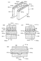
図12(A)は、図10に示した溝状窪部形成工程によって成形された圧力発生室形成
板30の一部を示す断面図であり、図11(c)に示すように研磨後の状態である。また
、同図(B)は、図11(a)(b)(c)に示した連通口形成工程によって成形された
圧力発生室形成板30の一部を示す断面図である。なお、図12の隔壁部28の厚さは、
理解しやすくするために、厚さを著しく分厚く図示してある。
FIG. 12A is a cross-sectional view showing a part of the pressure generating
For ease of understanding, the thickness is shown significantly thicker.
圧力発生室形成板30は、上述のように、ニッケル製の基板に鍛造加工を施したもので
あり、基板55の厚さは0.35mmであり、圧延工程をへて製造された圧延材が用いら
れている。図8,図10に示すように、上記第1雄型51には隔壁部28を成形するため
の空隙部53bが各突条部53のあいだに設けられている。この空隙部53bの空間幅は
隔壁部28の壁の厚さと実質的に同じであり、この例では31μmとされている。そして
、素材55がより円滑な状態で空隙部53b内に塑性流動を行うようにするために、この
例では上記ニッケルの結晶粒の粒径が15μmとされている。この粒径15μmは、隔壁
部の壁の厚さ31μmの約50%に相当している。
As described above, the pressure generation
また、この例において、上記ニッケル製素材55の硬度は、ビッカース硬度でHv17
0であり、伸びは10%である。
In this example, the
0 and the elongation is 10%.
上記のように結晶粒の平均粒径が、壁の厚さの60%以下15%以上である約50%とされていることにより、結晶粒の平均粒径が上記空隙部53bの幅を下回っているとともに、平均粒径は壁の厚さに対して過小でもなく過大でもない領域におかれているので、微細な空隙部53b内への結晶粒の流動が円滑になされ、良好な溝状窪部33の成形が行える。
As described above, the average grain size of the crystal grains is about 50%, which is 60% or less and 15% or more of the wall thickness, so that the average grain size of the crystal grains is less than the width of the
さらに、壁の厚さ方向で見た結晶粒の配列個数は多くて2個強,少なくて2個未満とな
り結晶粒の個数が異常に多くなるものではないので、上記空隙部53b内への塑性流動が
円滑になされる。もし、結晶粒の上記配列個数が多い側の上記個数を上回る場合には、壁
の厚さに対する結晶粒の増加により、結晶粒界が隔壁部28において増量することになる
ので、塑性変形性(転位の運動)が低下し、空隙部53b内への塑性流動性が低下して微
細な隔壁部28の塑性加工に支障を来すことになり、所定形状,所定寸法の溝状窪部がえ
にくくなる。
Further, since the number of crystal grains arranged in the thickness direction of the wall is at most 2 and less than 2 and the number of crystal grains does not increase abnormally, the plasticity into the
逆に、もし、結晶粒の上記配列個数が少ない側の上記個数を下回る場合には、塑性流動
は良好に果たされるが、結晶粒の大きさが隔壁部28にとっては過大になり、それにとも
なうニッケル材の強度低下のため、かえって微細な隔壁部28を高精度に加工することが
困難となる。
On the other hand, if the number of crystal grains is less than the above-mentioned number on the side where the number of crystal grains is small, the plastic flow is satisfactorily performed, but the size of the crystal grains becomes excessive for the
本発明によれば、結晶粒の配列個数に換算すると上記のような範囲の値になるので、上
記のように良好な塑性流動がえられて、所定の形状精度,寸法精度の溝状窪部33が成形
できるのである。また、結晶粒の粒径に注目した上記の数値(隔壁部28の壁の厚さの6
0%以下)により、塑性流動が円滑になされるので、溝状窪部33を成形する鍛造加工パ
ンチ51の割れや素材の焼き付き等が防止されて、耐久性が大幅に向上するうえ、微細形
状部の成形性を良好なものとしているのである。
According to the present invention, when converted into the number of crystal grains arranged, the value falls within the above range, so that a good plastic flow can be obtained as described above, and the groove-like recess having a predetermined shape accuracy and dimensional accuracy. 33 can be formed. Further, the above numerical value (6 of the wall thickness of the partition wall portion 28) focusing on the grain size of the crystal grains.
0% or less), the plastic flow is made smooth, so that the forging
上記ニッケルは、ビッカース硬度がHv170とされているので、ニッケル自体の硬度
が塑性流動に適した柔かな範囲の値とされているので、微細な溝状窪部33の成形が確実
に行える。また、鍛造加工にとっては柔かな領域の硬度であるから、鍛造加工パンチ51
(突条部53や先端部分53a等)の耐久性向上や加工精度の確保にとって有利である。
しかも、鍛造加工後の圧力発生室形成板30の剛性が確保でき、クロストークが防止され
、吐出特性の安定性を確保できる。また、鍛造加工中の素材強度が確保できて順送り加工
の際の取扱い性が確保されるうえ、鍛造加工後の圧力発生室形成板30の強度も確保され
、組み立て加工の際の取扱い性が確保される。
Since the nickel has a Vickers hardness of Hv170, the hardness of the nickel itself is set to a value in a flexible range suitable for plastic flow, so that the fine groove-shaped
This is advantageous for improving the durability of the
In addition, the rigidity of the pressure generating
さらに、上記ニッケルは、伸びが10%であるから、溝状窪部33の鍛造加工に必要な
素材55の伸びが十分に確保されているので、塑性流動は十分になされる。また、鍛造加
工時に生じる素材55の伸びは、上記伸びの範囲に対してわずかな量であるから、成形各
部における弾性復元力を可及的に少なくすることができる。このため、残留応力の少量化
にとって有効であり、鍛造加工後の弾性変形を実害のない範囲におさめることができ、溝
状窪部33の成形精度の向上や圧力発生室形成板30の湾曲変形の防止に有効である。
Further, since the nickel has an elongation of 10%, the elongation of the material 55 necessary for the forging process of the groove-
さらに、上記ニッケル素材は、引っ張り強さが400N/mm2以上600N/mm2
以下のものが好適であり、450N/mm2以上550N/mm2以下のものであればな
お好適である。このような強度に設定することにより、溝状窪部33の鍛造加工に必要な
素材55の変形量が十分に確保され、十分な塑性流動が生じて隔壁部28の成形が行なわ
れる。また、鍛造加工中の素材強度が確保できて順送り加工の際の取扱い性が確保される
うえ、鍛造加工後の圧力発生室形成板30の強度も確保され、組み立て加工の際の取扱い
性が確保される。しかも、鍛造加工後の圧力発生室形成板30の剛性が確保でき、クロス
トークが防止され、吐出特性の安定性を確保できる。
Furthermore, the nickel material has a tensile strength of 400 N / mm 2 or more and 600 N / mm 2.
The following ones are preferred, it is preferable noted as long as the 450 N / mm 2 or more 550 N / mm 2 or less. By setting such strength, a sufficient amount of deformation of the material 55 necessary for the forging process of the groove-
また、上記ニッケル素材は、ニッケル分が99重量%以上程度のものを用いることがで
きる。その化学成分の一例をあげると、下記のとおりである(単位:重量%)。
Ni : 99.9 以上
C : 0.03 以下
Si : 0.01 以下
Mn : 0.035 以下
P : 0.0030以下
S : 0.0030以下
Cr : 0.005 以下
Mo : 0.05 以下
Cu : 0.05 以下
O : 0.0030以下
In addition, the nickel material may have a nickel content of about 99% by weight or more. An example of the chemical component is as follows (unit:% by weight).
Ni: 99.9 or more C: 0.03 or less Si: 0.01 or less Mn: 0.035 or less P: 0.0030 or less S: 0.0030 or less Cr: 0.005 or less Mo: 0.05 or less Cu: 0.05 or less O: 0.0030 or less
図12に示す圧力発生室形成板を成形したときの上記ニッケルの結晶粒の粒径,硬度,
伸び等の設定数値についての評価結果は下記の表1に示すとおりである。このときの隔壁
部の壁の厚さは図示のとおり31μmである。
When the pressure generating chamber forming plate shown in FIG.
The evaluation results for the set numerical values such as elongation are as shown in Table 1 below. The wall thickness of the partition wall at this time is 31 μm as illustrated.
下記の表1からわかるように、隔壁部28の厚さに対するニッケルの結晶粒の粒径は、
80%未満(25μm未満)で比較的良好な結果が得られており、より好適な範囲は60
%以下(18μm以下)である。さらに好適なのは15%以上60%未満(5μm以上1
8μm未満)、さらには15%以上50%未満(5μm以上15μm以下)である。また
、15%以上60%未満(粒径5〜18μm)でも好結果が得られ、30%以上50%以
下(粒径10〜15μm)においてもより好結果が得られた。そして、最も好結果が得ら
れたのは15%以上30%未満(5μm以上10μm未満)である。
As can be seen from Table 1 below, the grain size of the nickel crystal grains relative to the thickness of the
Relatively good results have been obtained at less than 80% (less than 25 μm), and a more preferable range is 60
% Or less (18 μm or less). More preferable is 15% or more and less than 60% (5 μm or more and 1
Less than 8 μm), and further 15% or more and less than 50% (5 μm or more and 15 μm or less). Further, good results were obtained even at 15% or more and less than 60% (
また、硬度は、Hv150以上190未満で好結果が得られ、Hv160以上180以
下においてより好結果が得られた。また、伸びは5%超20%未満で好結果が得られ、1
0%以上20%未満においてより好結果が得られた。

A better result was obtained at 0% or more and less than 20%.
ニッケル製素材55は、ニッケルの圧延材であるから、圧延による素材板55の厚さが
高精度のもとで管理される。そして、このようにして品質管理の行われたニッケル圧延材
を鍛造加工の素材板55にするので、上記の各数値内における良好な鍛造加工が実現し、
高精度の溝状窪部33や隔壁部28が成形できる。さらに、圧延工程で形成されたニッケ
ルの組織状態に応じて、溝状窪部33の長手方向の向き等を選定することにより、より円
滑な塑性流動がえられる。
Since the
High-precision groove-
上記隔壁部28の厚さTを大きくすると、隔壁部28の剛性が確保されてクロストーク
が防止できるが、反面、圧力発生室29の列設配置密度が低下する。大きな厚さTを維持
したまま圧力発生室29の列設配置数を所定どおり求めると、今度は圧力発生室29の幅
が狭くなり、圧力発生室29の必要な容積が確保できなくなり、インクの吐出体積に不足
をきたすことになる。このような事情から各部の寸法の最適化が必要になる。上記隔壁部
28の厚さT=31μmに対する隔壁部28の高さH=45μmの比H/Tは、1.5で
あり、隔壁部28の剛性が低下しない程度の隔壁部28の高さHの比が確保できるので、
列設された溝状窪部33の剛性を適正に確保することができる。上記の比は、1.0〜2
.1の範囲内であれば、良好な隔壁部28の剛性が保持できるが、好ましくは、1.2〜
1.8であり、上記の1.5が最善である。
When the thickness T of the
The rigidity of the arranged groove-
. If it is within the range of 1, a good rigidity of the
1.8, with the above 1.5 being the best.
上記隔壁部28の厚さT=31μmに対する上記溝状窪部33の幅W=0.11mmの
比W/Tは、3.5あり、必要最小限の隔壁部28の壁の厚さTに対して十分な幅の溝状
窪部が形成できるので、溝状窪部の容積を所定どおりに確保するとともに、溝状窪部を最
も緻密な状態で列設し、単位長さ当たりの溝状窪部の列設数をできるだけ多くすることが
可能となる。上記の比は、2.0〜5.0の範囲内であれば、良好な溝状窪部の列設数が
えられるが、好ましくは、2.9〜4.5であり、上記の3.5が最善である。
The ratio W / T of the width W = 0.11 mm of the groove-
上記隔壁部28の厚さT=31μmに対する上記溝状窪部33の深さD=0.1mmの
比D/Tは、3.2であり、必要最小限の隔壁部28の壁の厚さTに対して十分な深さD
の溝状窪部33が形成できるので、溝状窪部33の容積を所定どおりに確保するとともに
、隔壁部28に十分な剛性を持たせることができる。上記の比は、2.0〜4.5の範囲
内であれば、良好な溝状窪部33の容積がえられるが、好ましくは、2.7〜4.0であ
り、上記の3.2が最善である。
The ratio D / T of the depth D = 0.1 mm of the groove-
Since the groove-shaped
上記溝状窪部33の底面は溝状窪部33の長手方向に延びるV字状の形状とされ、その
中央部が最深部になっている。このV字部分の内角θは90度であり、このような底面形
状により溝状窪部33の容積を十分に拡大することができる。このように深さの方向で容
積拡大ができることにより、溝状窪部33の幅を小さくすることができ、できるだけ多く
の溝状窪部33を列設することができる。上記の内角θは、45〜110度の範囲内であ
れば、良好な溝状窪部33の容積がえられるが、好ましくは、72〜100度であり、上
記の90度が最善である。
The bottom surface of the groove-
上記溝状窪部33のピッチ寸法は0.14mmであり、精密な微細部品であるインクジ
ェット式記録ヘッドの圧力発生室29を鍛造加工するようなときに、上記のような数値設
定(例えば、結晶粒の粒径が壁の厚さの60%以下等)により、きわめて微細な溝状窪部
の成形が可能となる。上記のピッチ寸法は、0.3mm以下とすることにより、液体噴射
ヘッド等の部品加工等においてより好適な仕上げとなる。好ましくは、0.2mm以下で
あり、上記の0.14mmが最善である。
The pitch dimension of the groove-shaped
上記圧力発生室形成板30の材料として、ニッケル板が採用されている。こうすること
により、ニッケル自体の線膨張係数が低く熱伸縮の現象が他の部品、例えばノズルプレー
ト31や弾性板32と同調して良好に果たされ、また、防錆性にすぐれ、さらに鍛造加工
で重要視される展性に富んでいる等、良好な効果がえられる。
A nickel plate is used as the material of the pressure generating
図12(B)は連通口34が形成された箇所の断面を示しており、上記のような結晶粒
の粒径,硬度,伸び等とされたニッケルに対して図11に示した連通口形成工程を施すこ
とにより、良好な穴あけ加工ができる。このように穴あけができるのは、穴あけ時に塑性
流動がなされつつ打抜かれる素材が少量であるから、その部分に含まれる結晶粒界の量が
比較的少なく、ニッケル素材を容易に打抜くことが可能となる。また、打抜かれる連通口
の大きさに対して結晶粒の粒径が比較的大きいものとされているので、素材の強度が打抜
きにとって適当な値となり、この点においても打抜きやすい条件となる。図12(B)の
場合は、隔壁部28の厚さと連通口34の内径寸法とが略同じであり、したがって、打抜
かれる素材量に含まれる結晶粒界の量が少なくて、打抜き加工時に雄型の第1連通口形成
部56や第2連通口形成部58の成形負荷が少なくなり、雄型の耐久性を高めるのにも有
効である。
FIG. 12B shows a cross section of the portion where the
上記のようなニッケル素材は、例えば、つぎのようにしてつくることができる。 The nickel material as described above can be produced, for example, as follows.
すなわち、図13に示すように、まず、真空溶解炉において原料ニッケルを溶解し、必
要に応じて脱ガス等を行なって鋳造してインゴットを得る。ついで、上記インゴットをプ
レスにより適当な大きさに分塊する。分塊されたブロック状のインゴットを熱間圧延する
ことにより所定の厚みの板状に成形したのち、表面研削を行なって表面状態を整える。つ
ぎに、冷間粗圧延を行なってさらに厚みを薄くしたのち、軟化焼鈍を行い、冷間粗圧延に
よって内部に蓄えられた歪を開放して軟化させるとともに、結晶粒径の調整を行なう。そ
して、最終的な冷間仕上げ圧延を行なって最終厚みの調節を行い圧延方向に切断する条取
りを行なって細長い帯状の最終製品を得る。
That is, as shown in FIG. 13, first, raw nickel is melted in a vacuum melting furnace, and degassing is performed as necessary to obtain an ingot. Next, the ingot is divided into an appropriate size by pressing. The block-shaped ingot that has been divided is hot-rolled to form a plate having a predetermined thickness, and then surface grinding is performed to adjust the surface state. Next, after performing cold rough rolling to further reduce the thickness, soft annealing is performed to release and soften the strain accumulated in the cold rough rolling, and the crystal grain size is adjusted. Then, the final cold finish rolling is performed, the final thickness is adjusted, and the strip is cut in the rolling direction to obtain an elongated strip-shaped final product.
ここで、上記軟化焼鈍の条件は、温度は400℃以上850度以下程度に設定され、時
間は数分〜数十分程度に設定される。上記焼鈍温度が低すぎたり焼鈍時間が短すぎたりす
ると十分な軟化が起こらず、上記機械的特性(すなわち硬度,引っ張り強度,伸び等が所
定の範囲内であること)の材料に設定することができない。反対に、焼鈍温度が高すぎた
り、焼鈍時間が長すぎたりすると、結晶粒が成長しすぎて所望の結晶粒径が得られなくな
る。このような観点から、上記焼鈍温度は、550℃以上850℃以下が好適であり、6
00度以上800℃以下がより好適であり、650℃以上750℃以下が最も好適である
。このときの焼鈍時間は、数分〜10分以内程度が好適である。
Here, the softening annealing conditions are such that the temperature is set to about 400 ° C. or more and 850 degrees or less, and the time is set to about several minutes to several tens of minutes. If the annealing temperature is too low or the annealing time is too short, sufficient softening will not occur, and the material should have the mechanical characteristics (that is, the hardness, tensile strength, elongation, etc. are within a predetermined range). Can not. On the other hand, if the annealing temperature is too high or the annealing time is too long, the crystal grains grow too much and the desired crystal grain size cannot be obtained. From such a viewpoint, the annealing temperature is preferably 550 ° C. or higher and 850 ° C. or lower.
It is more preferably from 00 ° to 800 ° C., and most preferably from 650 ° C. to 750 ° C. The annealing time at this time is preferably about several minutes to 10 minutes or less.
本発明の液体噴射ヘッドの製造方法においては、請求項1〜11のいずれか一項に記載
の寸法,形状を備えた溝状窪部33を圧力発生室形成板30に鍛造加工により成形するも
のである。
In the method of manufacturing a liquid jet head according to the present invention, the groove-shaped
したがって、上記のような数値設定、例えば、結晶粒の平均粒径が壁の厚さの60%以下15%以上,ニッケルのビッカース硬度がHv150以上Hv190未満,ニッケルの伸びが5%超20%未満等の条件下で圧力発生室形成板30に鍛造加工を行うことにより、より円滑な塑性流動がえられて、形状精度,寸法精度の高い圧力発生室形成板30が形成され、引いては良好な液体噴射特性を備えた液体噴射ヘッド1が製造できる。また、上述のような値設定により、鍛造加工パンチの負担が少なくてその耐久性が著しく長期化される。
Therefore, the above numerical setting, for example, the average grain size of the crystal grains is 60% or less 15% or more of the wall thickness, the nickel Vickers hardness is Hv 150 or more and less than Hv 190, and the nickel elongation is more than 5% but less than 20% By performing the forging process on the pressure generating
図14〜図18は、本発明の液体噴射ヘッドおよびその製法の第2の実施の形態を示す
。
14 to 18 show a liquid jet head according to a second embodiment of the invention and a manufacturing method thereof.
この製造方法では、圧力発生室形成板30の製造工程における溝状窪部33を形成する
溝状窪部形成工程が上記実施の形態と相違する。
In this manufacturing method, the groove-like recess forming step for forming the groove-
この実施の形態の溝状窪部形成工程でも、図8に示したような雄型51と図9に示した
ような雌型52とを用いるが、雌型52の筋状突起54が圧力発生室29のピッチに対し
て半ピッチだけ圧力発生室29の列設方向にずれて配置されている。
Also in the groove-like recess forming step of this embodiment, the
すなわち、上記雄型51が第1金型51aであり、また、雌型52が第2金型52aで
ある。第2金型52aに設けられた筋状突起54は、上記突条部53と略同じ長さで突条
部53の長手方向と同じ方向に多数設けられ、突条部53と筋状突起54とが対向した位
置関係とされている。このような位置関係なので、第1金型51aと第2金型52aの間
で素材(圧力発生室形成板30)が加圧されると、突条部53と筋状突起54の間に存在
する素材の加圧量が最も多くなる。
That is, the
そして、溝状窪部形成工程では、まず、図14(a)に示すように、雌型52の上面に
素材であるとともに圧力発生室形成板である帯板55を載置し、帯板55の上方に雄型5
1を配置する。次に、図14(b)に示すように、雄型51を下降させて突条部53の先
端部を帯板55内に押し込む。このとき、突条部53の先端部分53aをV字状に尖らせ
ているので、突条部53を座屈させることなく先端部分53aを帯板55内に確実に押し
込むことができる。この突条部53の押し込みは、図14(c)に示すように、帯板55
の板厚方向の途中まで行う。
In the groove-shaped recess forming step, first, as shown in FIG. 14A, a
1 is placed. Next, as shown in FIG. 14 (b), the
To the middle of the plate thickness direction.
突条部53の押し込みにより、帯板55の一部分が流動し、溝状窪部33が形成される
。ここで、突条部53の先端部分53aがV字状に尖っているので、微細な形状の溝状窪
部33であっても、高い寸法精度で作製することができる。すなわち、先端部分53aで
押された部分が円滑に流れるので、形成される溝状窪部33は突条部53の形状に倣った
形状に形成される。このときに、先端部分53aで押し分けられるようにして流動した素
材55は、突条部53のあいだに設けられた空隙部53b内に流入し隔壁部28が成形さ
れる。さらに、先端部分53aにおける長手方向の両端も面取りしてあるので、当該部分
で押圧された帯板55も円滑に流れる。従って、溝状窪部33の長手方向両端部について
も高い寸法精度で作製できる。
When the
また、突条部53の押し込みを板厚方向の途中で止めているので、貫通孔として形成す
る場合よりも厚い帯板55を用いることができる。これにより、圧力発生室形成板30の
剛性を高めることができ、インク滴の吐出特性の向上が図れる。また、圧力発生室形成板
30の取り扱いも容易になる。
Moreover, since pushing of the
また、突条部53で押圧されたことにより、帯板55の一部は隣り合う突条部53,5
3の空間内すなわち空隙部53b内に隆起する。そして、本発明では、塑性加工の対象素
材であるニッケル素材を上記のような数値設定、例えば、結晶粒の粒径が壁の厚さの60
%以下,ニッケルのビッカース硬度がHv150以上Hv190未満,ニッケルの伸びが
5%超20%未満等とし、そのニッケル素材を、上記のように対向した位置関係の突条部
53と筋状突起54との間で塑性加工することから、突条部53と筋状突起54の間の最
も多く加圧する部分の素材55の塑性流動が空隙部53bに向って極めて積極的に行われ
、突条部53間の空間(空隙部53b)に対して効率よく素材の塑性流動がなされて、隔
壁部28を高く形成できる。
Further, by being pressed by the
3 bulges in the
%, Nickel Vickers hardness of Hv150 or more and less than Hv190, nickel elongation of more than 5% and less than 20%, etc. Therefore, the plastic flow of the material 55 in the most pressurized portion between the protruding
このような条件下で圧力発生室形成板30に鍛造加工を行うことにより、より円滑な塑
性流動がえられて、形状精度,寸法精度の高い圧力発生室形成板30が形成され、引いて
は良好な液体噴射特性を備えた液体噴射ヘッド1が製造できる。また、上述のような数値
設定により、鍛造加工パンチの負担が少なくてその耐久性が著しく長期化されるのである
。
By forging the pressure generation
なお、図14の(d)は実線図示の突条部53と2点鎖線図示の筋状突起54との位置
関係を平面的に示したもので、筋状突起54が、上記突条部53と略同じ長さで突条部5
3の長手方向と同じ方向に多数設けられ、突条部53と筋状突起54とが対向した位置関
係とされている。
FIG. 14D is a plan view showing the positional relationship between the
3 is provided in the same direction as the
ここで、溝状窪部33の成形精度、とりわけ隔壁部28の成形処理が重要となる。この
ような要請に応えるために、本発明では、圧力発生室形成板30(素材,帯板,金属素材
板55)の塑性流動を規制して、適正な隔壁部28を成形するようにしている。それと同
時に、鍛造加工パンチに第1金型と、仮成形金型と仕上げ金型からなる第2金型を保有さ
せ、第2金型に特殊な形状を付与して、隔壁部28の形状の適正化を図っている。
Here, the molding accuracy of the groove-
図15〜図18は、まず最初に、上記第1金型と特殊な形状を付与した第2金型によっ
て隔壁部28や溝状窪部33が成形される加工工程を示している。なお、すでに説明され
た部位と同じ機能を果たす部位については、同一の符号を図中に記載してある。
FIGS. 15 to 18 show a processing step in which the
なお、前述の雄型51および雌型52により帯板(素材)55に塑性加工を行うときに
は、常温の温度条件下であり、また、以下に説明する塑性加工においても同様に常温の温
度条件で塑性加工を行っている。
When plastic working is performed on the strip (material) 55 by the
雄型51aすなわち第1金型に、多数の成形パンチ51bが配列されている。溝状窪部
33を成形するために、この成形パンチ51bを細長く変形して、突条部53cとされて
いる。そして、この突条部53cは、所定ピッチで平行に配列されている。また、隔壁部
28を成形するために、上記成形パンチ51bの間に空隙部53b(図8,図14参照)
が設けられている。上記第1金型51aが素材である圧力発生室形成板30(55)に押
込まれた状態が、図16(C)に示してある。
A large number of molding punches 51b are arranged in the male mold 51a, that is, the first mold. In order to form the groove-
Is provided. FIG. 16C shows a state where the first mold 51a is pushed into the pressure generating chamber forming plate 30 (55), which is a material.
一方、上記雌型52aすなわち第2金型は、上記突条部53cの長手方向における中間
部に対応する部分に、突条部53cの配列方向に延びる凹部54aが設けられている。そ
して、第2金型52aには、仮成形金型63と仕上げ金型64の2種類の金型が準備され
ている。
On the other hand, the female mold 52a, that is, the second mold, is provided with a recess 54a extending in the arrangement direction of the ridges 53c at a portion corresponding to an intermediate part in the longitudinal direction of the ridges 53c. In the second mold 52a, two types of molds, a
上記第2金型52aは、仮成形用の仮成形金型63と、該仮成形金型63による仮成形
後に仕上げ加工を行うための仕上げ金型64とを有しているので、上記仮成形金型63に
より素材55を空隙部53b内に流動させ、その後、仕上げ金型64により空隙部53b
内における素材55の分布を正常な状態に可及的に近づけるので、空隙部53b内への素
材流入量が空隙部53bの長さ方向において略真直ぐな状態になり、液体噴射ヘッド1の
圧力発生室29の隔壁部28として機能させるときに好都合である。
Since the second mold 52a includes a
Since the distribution of the material 55 in the inside is as close as possible to the normal state, the amount of material flowing into the
このような第2金型52aの構成や作動を詳細に述べると次のとおりである。 The configuration and operation of the second mold 52a will be described in detail as follows.
上記仮成形金型63には上記突条部53cに対向するとともにこの突条部53cと略同
じ長さの筋状突起54が形成されている。そして、この筋状突起54にはその長さ方向に
おける中間部の高さが低く設定された凹部54aが設けられている。図14は、多数配列
されている筋状突起54のなかの1つを示す側面図であり、同図(A)では中央部に円弧
状の凹部54aが形成されている。
The temporary molding die 63 is formed with
上記筋状突起54は、図9や図10に示したものは、高さの低い突条のような部材形状
であるが、凹部54aを形成するためには、筋状突起54に図16および図18に示すよ
うな所要の高さが必要とされている。したがって、このような凹部54aが形成された筋
状突起54は、高さのある「突条」が多数平行に配列されたもので、図16では断面形状
が先端の尖った楔形状とされている。この楔形状部分の楔角度は、90度以下の鋭角とさ
れている。なお、筋状突起54の配列により谷部63aが形成されている。また、圧力発
生室形成板30(素材55)の裏面に後述の仮成形工程で成形される隆起部55aが図示
されている。
9 and FIG. 10 is a member shape like a protrusion having a low height. In order to form the recess 54a, the
上記筋状突起54の長手方向の凹部54aの長さは、筋状突起54の長さの約2/3以
下に設定してある。また、筋状突起54のピッチは0.14mmである。この筋状突起5
4のピッチについては、0.3mm以下とすることにより、液体噴射ヘッド等の部品加工
等においてより好適な予備成形となる。このピッチは好ましくは0.2mm以下,より好
ましくは0.15mm以下である。さらに、筋状突起54の少なくとも凹部54aの部分
は、その表面が平滑に仕上げられている。この仕上げとしては、鏡面仕上げが適している
が、他に例えば、クロム鍍金を施してもよい。
The length of the recess 54 a in the longitudinal direction of the
By setting the pitch of 4 to 0.3 mm or less, pre-molding is more suitable for parts processing such as a liquid jet head. This pitch is preferably 0.2 mm or less, more preferably 0.15 mm or less. Further, at least the concave portion 54a of the streak-
上記楔形状部分の稜線部分を削り取るようにして形成されたのが、図18の(A)〜(
F)の示すような凹部54aである。(A)は前述のように円弧状,(B)は平面で構成
された凹部形状,(C)は両端部が小さな曲面とされ大部分が平面とされた凹部形状,(
D)は両端部が平坦な傾斜面とされ中央部が平面とされた凹部形状,(E)(F)は凹部
の中間部分に隆起形状部54bが設けられている凹部形状である。上記のように楔形状部
分の稜線部分を削り取って凹部54aが形成されているので、凹部54aの頂面は図18
(A2)のように断面で見ると平面となり、凹部全体では細長い円弧面になっている。
18A to 18D are formed by scraping the ridge line portion of the wedge-shaped portion.
A concave portion 54a as shown in FIG. (A) is an arc shape as described above, (B) is a concave shape constituted by a plane, (C) is a concave shape having both ends are small curved surfaces and most are flat,
D) is a concave shape in which both end portions are flat inclined surfaces and the central portion is flat, and (E) and (F) are concave shapes in which a raised portion 54b is provided in the middle portion of the concave portion. Since the concave portion 54a is formed by scraping the ridge line portion of the wedge-shaped portion as described above, the top surface of the concave portion 54a is shown in FIG.
When viewed in cross section as in (A2), it becomes a flat surface, and the entire concave portion has a long and narrow circular arc surface.
上記の筋状突起54は楔形状で先端部が尖っているが、素材55の移動状態等により図
18(G)に示すように平坦な頂面54cまたは丸みのある先端部の形状にしてもよい。
The
つぎに、上記第2金型52aの仕上げ金型64は、上記仮成形金型63による仮成形後
に使用されるもので、この仕上げ金型64には仮成形金型63の筋状突起54が除去され
た平坦面64aが形成され、また、仮成形金型63の凹部54aに対応する箇所に収容凹
部64bが形成されている。すなわち、仕上げ金型64の成形面の幅方向で見て、中央部
に収容凹部64bが形成され、この収容凹部64bの両側に平坦面64aが設けられてい
る。
Next, the finishing
そして、楔形の仮成形金型63による仮成形ののち、平坦面64aと凹部64bが存在
する仕上げ金型64で仕上げ成形することにより、仮成形時の塑性流動で素材55がある
程度空隙部53b内に流動し、その後の平坦面64aによる加圧で空隙部53b内での上
向きの塑性流動がさらに促進され、十分な高さの隔壁部28が成形できる。また、仕上げ
金型64の凹部64bの存在により、圧力発生室29の長手方向中央近傍よりも、両端寄
りの部分においてより強い加工が行なわれ、圧力発生室29の長手方向での隔壁部28の
高さ寸法の均一性が向上する。
Then, after temporary molding by the wedge-shaped temporary molding die 63, finish molding is performed by the finishing die 64 having the flat surface 64a and the
上記平坦面64aは、図17(A)に示すように、上記突条部53cの配列方向におけ
る端部近傍の箇所が端部に向かって低くなる表面形状となっており、当該徐々に低くなる
部分は、上記平坦面64aに連続した傾斜面64cである。当該端部近傍では列の外側方
向への肉の流れが生じて隔壁部28の高さが低くなりがちであるが、平坦面64aの突条
部53cの配列方向における端部近傍の箇所に、徐々に下り傾斜する傾斜面64cを設け
たことから、仕上げ成形後における隔壁部28の圧力発生室29列設方向の高さ寸法の均
一性が向上する。
As shown in FIG. 17A, the flat surface 64a has a surface shape in which a portion in the vicinity of the end in the arrangement direction of the protrusions 53c becomes lower toward the end, and gradually decreases. The portion is an
そして、本発明では、塑性加工の対象素材であるニッケル素材を上記のような数値設定、例えば、結晶粒の平均粒径が壁の厚さの60%以下15%以上,ニッケルのビッカース硬度がHv150以上Hv190未満,ニッケルの伸びが5%超20%未満等とし、そのニッケル素材を、上記のように仮成形金型63による仮成形のあとに仕上げ金型64による加圧を行なうことから、仮成形時の楔打ち込み効果による空隙部53b内の塑性流動や、仕上げ成形時の加圧による空隙部53b内の塑性流動が促進され、十分な高さの隔壁部28が成形できるのである。
In the present invention, the nickel material, which is the target material for plastic working, is numerically set as described above. For example, the average grain size of the crystal grains is 60% or less 15% or more of the wall thickness, and the nickel Vickers hardness is Hv150. Since the Hv is less than 190, the elongation of nickel is more than 5% and less than 20%, the nickel material is pressed by the finishing
このような条件下で圧力発生室形成板30に鍛造加工を行うことにより、より円滑な塑
性流動がえられて、形状精度,寸法精度の高い圧力発生室形成板30が形成され、引いて
は良好な液体噴射特性を備えた液体噴射ヘッド1が製造できる。また、上述のような数値
設定により、鍛造加工パンチの負担が少なくてその耐久性が著しく長期化されるのである
。
By forging the pressure generation
上記第1金型51aと第2金型52aは、金型が進退動作をする通常の鍛造加工装置(
図示していない)に固定され、両金型51aと52aのあいだに圧力発生室形成板30(
55)を配置して、順次加工がなされる。また、第2金型52aは仮成形金型63と仕上
げ金型64が組になって構成されているので、仮成形金型63と仕上げ金型64を順送り
式の鍛造加工装置に隣合わせて配列し、圧力発生室形成板30(55)を順次移行させる
のが適当である。
The first mold 51a and the second mold 52a are made up of a normal forging device (a normal forging apparatus in which the mold moves back and forth (
The pressure generating chamber forming plate 30 (not shown) is fixed between the molds 51a and 52a.
55) is arranged and processing is performed sequentially. Further, since the second mold 52a is constituted by a
図19に例示した記録ヘッド1´は、本発明を適用することのできる事例であり、圧力
発生素子として発熱素子61を用いたものである。この例では、上記の弾性板32に代え
て、コンプライアンス部46とインク供給口45とを設けた封止基板62を用い、この封
止基板62によって圧力発生室形成板30における溝状窪部33側を封止している。また
、この例では、圧力発生室29内における封止基板62の表面に発熱素子61を取り付け
ている。この発熱素子61は電気配線を通じて給電されて発熱する。なお、圧力発生室形
成板30やノズルプレート31等、その他の構成は上記実施形態と同様であるので、その
説明は省略する。
A
この記録ヘッド1´では、発熱素子61への給電により、圧力発生室29内のインクが
突沸し、この突沸によって生じた気泡が圧力発生室29内のインクを加圧する。この加圧
により、ノズル開口48からインク滴が吐出される。そして、この記録ヘッド1´でも、
圧力発生室形成板30を金属の塑性加工で作製しているので、上記した実施形態と同様の
作用効果を奏する。
In the
Since the pressure generating
また、連通口34に関し、上記実施形態では、溝状窪部33の一端部に設けた例を説明
したが、これに限らない。例えば、連通口34を溝状窪部33における長手方向略中央に
形成して、溝状窪部33の長手方向両端にインク供給口45及びそれと連通する共通イン
ク室14を配置してもよい。このようにすることによりインク供給口45から連通口34
に至る圧力発生室29内におけるインクの淀みを防止できるので、好ましい。
Moreover, although the example provided in the one end part of the groove-shaped recessed
This is preferable because the ink stagnation in the
上述の実施の形態は、インクジェット式記録装置に使用される記録ヘッドであるが、本
発明における液体噴射ヘッドは、インクジェット式記録装置用のインクだけを対象にする
のではなく、グルー,マニキュア,導電性液体(液体金属)等を噴射することができる。
The above-described embodiment is a recording head used in an ink jet recording apparatus. However, the liquid ejecting head in the present invention is not only intended for ink for an ink jet recording apparatus, but is a glue, a nail polish, a conductive material. Liquid (liquid metal) or the like can be ejected.
上記のようにニッケルの結晶粒の平均粒径が、壁の厚さの60%以下15%以上であることにより、結晶粒の平均粒径が上記空隙部の幅を下回っているとともに、平均粒径は壁の厚さに対して過小でもなく過大でもない領域におかれているので、微細な空隙部内への結晶粒の流動が円滑になされ、良好な溝状窪部の成形が行える。
As described above, when the average grain size of the nickel crystal grains is 60% or less and 15% or more of the wall thickness, the average grain size of the crystal grains is less than the width of the void portion, and the average grain size Since the diameter is in a region that is neither too small nor too large with respect to the wall thickness, the crystal grains smoothly flow into the fine voids, and a good groove-like depression can be formed.
さらに、壁の厚さ方向で見た結晶粒の配列個数は多くて2個強,少なくて2個未満とな
り結晶粒の個数が異常に多くなるものではないので、上記空隙部内への塑性流動が円滑に
なされる。もし、結晶粒の上記配列個数が多い側の上記個数を上回る場合には、壁の厚さ
に対する結晶粒の増加により、結晶粒界が隔壁部において増量することになるので、塑性
変形性(転位の運動)が低下し、空隙部内への塑性流動性が低下して微細な隔壁部の塑性
加工に支障を来すことになり、所定形状,所定寸法の溝状窪部がえにくくなる。
Furthermore, the number of crystal grains arranged in the thickness direction of the wall is a little more than two, and less than two, and the number of crystal grains does not increase abnormally. It is made smoothly. If the number of crystal grains is larger than the number on the side where the number of crystal grains is larger, the number of crystal grains increases with respect to the wall thickness. ), The plastic fluidity into the gap portion is lowered, and the plastic working of the fine partition wall portion is hindered, and it becomes difficult to obtain a groove-like recess portion having a predetermined shape and a predetermined size.
逆に、もし、結晶粒の上記配列個数が少ない側の上記個数を下回る場合には、塑性流動
は良好に果たされるが、結晶粒の大きさが隔壁部にとっては過大になり、それにともなう
ニッケル材の強度低下のため、かえって微細な隔壁部を高精度に加工することが困難とな
る。
On the other hand, if the number of crystal grains is less than the above number on the side where the number of the crystal grains is small, plastic flow is satisfactorily performed, but the size of the crystal grains becomes excessive for the partition wall, and the nickel material associated therewith. However, it is difficult to process a fine partition wall with high accuracy.
本発明によれば、結晶粒の配列個数に換算すると上記のような範囲の値になるので、上記のように良好な塑性流動がえられて、所定の形状精度,寸法精度の溝状窪部が成形できるのである。また、結晶粒の平均粒径に注目した上記の数値(隔壁部の壁の厚さの60%以下15%以上)により、塑性流動が円滑になされるので、溝状窪部を成形する鍛造加工パンチの割れや素材の焼き付き等が防止されて、耐久性が大幅に向上するうえ、微細形状部の成形性を良好なものとしているのである。
According to the present invention, when converted into the number of crystal grains arranged, the value falls within the above range, so that a good plastic flow can be obtained as described above, and the groove-like recess having a predetermined shape accuracy and dimensional accuracy. Can be molded. In addition, the above numerical value (60% or less and 15% or more of the wall thickness of the partition wall portion) that focuses on the average grain size of the crystal grains facilitates plastic flow, so that forging processing for forming the groove-like recess Punch breakage and material seizure are prevented, and the durability is greatly improved and the moldability of the finely shaped portion is improved.
1 インクジェット式記録ヘッド
1´ インクジェット式記録ヘッド
2 ケース
3 振動子ユニット
4 流路ユニット
5 接続基板
6 供給針ユニット
7 圧電振動子群
8 固定板
9 フレキシブルケーブル
10 圧電振動子
10a ダミー振動子
10b 駆動振動子
11 制御用IC
12 収納空部
13 インク供給路
14 共通インク室
15 先端凹部
16 接続口
17 コネクタ
18 針ホルダ
19 インク供給針
20 フィルタ
21 台座
22 インク排出口
23 パッキン
28 隔壁部
29 圧力発生室
30 圧力発生室形成板
31 ノズルプレート
32 弾性板
33 溝状窪部
34 連通口
35 逃げ凹部
36 ダミー窪部,ダミー圧力発生室
37 第1連通口
38 第2連通口
39 ダミー連通口
40 第1ダミー連通口
41 第2ダミー連通口
42 支持板
43 弾性体膜
44 ダイヤフラム部
45 インク供給口
46 コンプライアンス部
47 島部
48 ノズル開口
51 第1雄型,鍛造加工パンチ
51a 第1金型
51b 成形パンチ
51c 二股部
52 雌型
52a 第2金型
53 突条部
53a 先端部分
53b 空隙部
53c 突条部
54 筋状突起
54a 凹部
54b 隆起形状部
54c 頂面
55 帯板,素材,金属素材板,(圧力発生室形成板)
55a 隆起部
56 第1連通口形成部
57 第2雄型
58 第2連通口形成部
59 第3雄型
61 発熱素子
62 封止基板
63 仮成形金型
63a 谷部
64 仕上げ金型
64a 平坦面
64b 収容凹部
64c 傾斜面
75 凹条
T 隔壁部の厚さ寸法
H 隔壁部の高さ寸法
W 溝状窪部の幅寸法
D 溝状窪部の深さ寸法
θ V型底部の内角
DESCRIPTION OF
DESCRIPTION OF
55a Raised
Claims (12)
Forgings in which groove-like recesses that serve as pressure generating chambers are arranged in the width direction of the groove-like recesses via partition walls, and a communication port that penetrates in the thickness direction is formed at one end of each groove-like recess. A nickel pressure generation chamber forming plate formed by processing, a metal nozzle plate having a nozzle opening formed at a position corresponding to the communication port, and a sealing plate for sealing the opening surface of the groove-like recess. A method of manufacturing a liquid jet head comprising a flow path unit formed by joining a sealing plate on the groove-like recess side of the pressure generating chamber forming plate and a nozzle plate on the opposite side, respectively. A method for manufacturing a liquid jet head, comprising forming a groove-like recess having the size and shape according to any one of the above items into a pressure generating chamber forming plate by forging.
Priority Applications (6)
| Application Number | Priority Date | Filing Date | Title |
|---|---|---|---|
| JP2003290643A JP3729190B2 (en) | 2002-08-23 | 2003-08-08 | Liquid jet head and manufacturing method thereof |
| EP03018713A EP1391304B1 (en) | 2002-08-23 | 2003-08-25 | Liquid ejection head, and method of manufacturing the same |
| US10/647,669 US7052119B2 (en) | 2002-08-23 | 2003-08-25 | Liquid ejection head, and method of manufacturing the same |
| AT03018713T ATE376934T1 (en) | 2002-08-23 | 2003-08-25 | LIQUID DISCHARGE HEAD AND ASSOCIATED MANUFACTURING METHOD |
| CNB031538428A CN1269647C (en) | 2002-08-23 | 2003-08-25 | Liquid ejection head, and method of manufacturing the same |
| DE60317143T DE60317143T2 (en) | 2002-08-23 | 2003-08-25 | Liquid ejection head and associated manufacturing method |
Applications Claiming Priority (2)
| Application Number | Priority Date | Filing Date | Title |
|---|---|---|---|
| JP2002243483 | 2002-08-23 | ||
| JP2003290643A JP3729190B2 (en) | 2002-08-23 | 2003-08-08 | Liquid jet head and manufacturing method thereof |
Publications (2)
| Publication Number | Publication Date |
|---|---|
| JP2004098672A JP2004098672A (en) | 2004-04-02 |
| JP3729190B2 true JP3729190B2 (en) | 2005-12-21 |
Family
ID=31190389
Family Applications (1)
| Application Number | Title | Priority Date | Filing Date |
|---|---|---|---|
| JP2003290643A Expired - Fee Related JP3729190B2 (en) | 2002-08-23 | 2003-08-08 | Liquid jet head and manufacturing method thereof |
Country Status (6)
| Country | Link |
|---|---|
| US (1) | US7052119B2 (en) |
| EP (1) | EP1391304B1 (en) |
| JP (1) | JP3729190B2 (en) |
| CN (1) | CN1269647C (en) |
| AT (1) | ATE376934T1 (en) |
| DE (1) | DE60317143T2 (en) |
Families Citing this family (10)
| Publication number | Priority date | Publication date | Assignee | Title |
|---|---|---|---|---|
| JP4517778B2 (en) * | 2004-08-30 | 2010-08-04 | セイコーエプソン株式会社 | Fine hole drilling method and liquid jet head manufacturing apparatus |
| JP2006068767A (en) * | 2004-09-01 | 2006-03-16 | Seiko Epson Corp | Method for piercing fine hole, tool used for the same, and method and apparatus for manufacturing liquid injection head |
| JP4639718B2 (en) * | 2004-09-22 | 2011-02-23 | セイコーエプソン株式会社 | Pressure generating chamber forming plate manufacturing apparatus for liquid ejecting head, pressure generating chamber forming plate manufacturing method for liquid ejecting head, and liquid ejecting head |
| JP4513661B2 (en) * | 2005-06-15 | 2010-07-28 | セイコーエプソン株式会社 | Liquid jet head |
| US7658477B2 (en) | 2005-11-11 | 2010-02-09 | Ricoh Company, Ltd. | Liquid ejecting head, imaging forming apparatus, device for ejecting a liquid drop, and recording method |
| JP4924803B2 (en) * | 2006-03-28 | 2012-04-25 | ブラザー工業株式会社 | Water-based ink for inkjet recording |
| JP4301306B2 (en) * | 2007-02-26 | 2009-07-22 | セイコーエプソン株式会社 | Liquid ejecting head and liquid ejecting apparatus |
| US8528209B2 (en) * | 2009-12-15 | 2013-09-10 | Canon Kabushiki Kaisha | Method for manufacturing discharge port member and method for manufacturing liquid discharge head |
| JP2012152967A (en) * | 2011-01-25 | 2012-08-16 | Seiko Epson Corp | Liquid jet head and liquid jet device |
| JP6859670B2 (en) * | 2016-11-11 | 2021-04-14 | セイコーエプソン株式会社 | Liquid discharge head |
Family Cites Families (9)
| Publication number | Priority date | Publication date | Assignee | Title |
|---|---|---|---|---|
| US3523224A (en) * | 1968-11-12 | 1970-08-04 | Sprague Electric Co | Nickel-nickel oxide capacitor |
| US3895942A (en) * | 1971-06-25 | 1975-07-22 | Int Nickel Co | Strong, high purity nickel |
| JPS5514283A (en) * | 1978-07-18 | 1980-01-31 | Seiko Epson Corp | Manufacturing method of recording ink jetting head |
| US4430784A (en) * | 1980-02-22 | 1984-02-14 | Celanese Corporation | Manufacturing process for orifice nozzle devices for ink jet printing apparati |
| JPS6173851A (en) | 1984-09-17 | 1986-04-16 | Natl Res Inst For Metals | Superplastic ni alloy for forging and its manufacture |
| EP0974466B1 (en) * | 1995-04-19 | 2003-03-26 | Seiko Epson Corporation | Ink jet recording head and method of producing same |
| US6145963A (en) * | 1997-08-29 | 2000-11-14 | Hewlett-Packard Company | Reduced size printhead for an inkjet printer |
| JP3389986B2 (en) | 1999-01-12 | 2003-03-24 | セイコーエプソン株式会社 | Inkjet recording head |
| WO2001042018A1 (en) * | 1999-12-13 | 2001-06-14 | Fujitsu Limited | Ink-jet head and method of manufacture thereof |
-
2003
- 2003-08-08 JP JP2003290643A patent/JP3729190B2/en not_active Expired - Fee Related
- 2003-08-25 DE DE60317143T patent/DE60317143T2/en not_active Expired - Lifetime
- 2003-08-25 CN CNB031538428A patent/CN1269647C/en not_active Expired - Fee Related
- 2003-08-25 EP EP03018713A patent/EP1391304B1/en not_active Expired - Lifetime
- 2003-08-25 AT AT03018713T patent/ATE376934T1/en not_active IP Right Cessation
- 2003-08-25 US US10/647,669 patent/US7052119B2/en not_active Expired - Fee Related
Also Published As
| Publication number | Publication date |
|---|---|
| CN1269647C (en) | 2006-08-16 |
| US7052119B2 (en) | 2006-05-30 |
| DE60317143T2 (en) | 2008-08-07 |
| US20040125178A1 (en) | 2004-07-01 |
| CN1485207A (en) | 2004-03-31 |
| JP2004098672A (en) | 2004-04-02 |
| ATE376934T1 (en) | 2007-11-15 |
| DE60317143D1 (en) | 2007-12-13 |
| EP1391304A1 (en) | 2004-02-25 |
| EP1391304B1 (en) | 2007-10-31 |
Similar Documents
| Publication | Publication Date | Title |
|---|---|---|
| US8998387B2 (en) | Method of working small recess portion, method of fabricating liquid ejection head and liquid ejection head | |
| JP3729190B2 (en) | Liquid jet head and manufacturing method thereof | |
| JP3632701B2 (en) | Liquid jet head and manufacturing method thereof | |
| JP3736550B2 (en) | Fine hole drilling apparatus, processing method therefor, and liquid jet head manufacturing method using the same | |
| JP4407180B2 (en) | Method and apparatus for manufacturing liquid jet head, mold, and liquid jet head obtained thereby | |
| JP4349282B2 (en) | Fine forging method and liquid jet head manufacturing method | |
| JP3654296B2 (en) | Method for manufacturing liquid jet head | |
| US20060174737A1 (en) | Manufacturing method of die for manufacturing liquid ejecting head, and material block used in the same | |
| JP4517778B2 (en) | Fine hole drilling method and liquid jet head manufacturing apparatus | |
| JP4770845B2 (en) | Liquid jet head | |
| JP3757965B2 (en) | Fine hole drilling method, liquid ejecting head manufacturing method using the same, and liquid ejecting head manufacturing apparatus | |
| JP3807389B2 (en) | Male mold, liquid jet head, liquid jet head manufacturing method, and forging device | |
| JP4639718B2 (en) | Pressure generating chamber forming plate manufacturing apparatus for liquid ejecting head, pressure generating chamber forming plate manufacturing method for liquid ejecting head, and liquid ejecting head | |
| US7194886B2 (en) | Method for forging plate and method for manufacturing a liquid ejection head | |
| JP4604471B2 (en) | Method of manufacturing liquid jet head and liquid jet head obtained thereby | |
| JP3794401B2 (en) | Method for manufacturing liquid jet head | |
| JP4729840B2 (en) | Method of manufacturing liquid jet head and liquid jet head obtained thereby | |
| JP2006068767A (en) | Method for piercing fine hole, tool used for the same, and method and apparatus for manufacturing liquid injection head |
Legal Events
| Date | Code | Title | Description |
|---|---|---|---|
| A977 | Report on retrieval |
Free format text: JAPANESE INTERMEDIATE CODE: A971007 Effective date: 20050128 |
|
| A131 | Notification of reasons for refusal |
Free format text: JAPANESE INTERMEDIATE CODE: A131 Effective date: 20050208 |
|
| A521 | Request for written amendment filed |
Free format text: JAPANESE INTERMEDIATE CODE: A523 Effective date: 20050408 |
|
| TRDD | Decision of grant or rejection written | ||
| A01 | Written decision to grant a patent or to grant a registration (utility model) |
Free format text: JAPANESE INTERMEDIATE CODE: A01 Effective date: 20050913 |
|
| A61 | First payment of annual fees (during grant procedure) |
Free format text: JAPANESE INTERMEDIATE CODE: A61 Effective date: 20050926 |
|
| R150 | Certificate of patent or registration of utility model |
Free format text: JAPANESE INTERMEDIATE CODE: R150 |
|
| FPAY | Renewal fee payment (event date is renewal date of database) |
Free format text: PAYMENT UNTIL: 20091014 Year of fee payment: 4 |
|
| FPAY | Renewal fee payment (event date is renewal date of database) |
Free format text: PAYMENT UNTIL: 20101014 Year of fee payment: 5 |
|
| FPAY | Renewal fee payment (event date is renewal date of database) |
Free format text: PAYMENT UNTIL: 20101014 Year of fee payment: 5 |
|
| FPAY | Renewal fee payment (event date is renewal date of database) |
Free format text: PAYMENT UNTIL: 20111014 Year of fee payment: 6 |
|
| FPAY | Renewal fee payment (event date is renewal date of database) |
Free format text: PAYMENT UNTIL: 20121014 Year of fee payment: 7 |
|
| FPAY | Renewal fee payment (event date is renewal date of database) |
Free format text: PAYMENT UNTIL: 20121014 Year of fee payment: 7 |
|
| FPAY | Renewal fee payment (event date is renewal date of database) |
Free format text: PAYMENT UNTIL: 20131014 Year of fee payment: 8 |
|
| LAPS | Cancellation because of no payment of annual fees |