JP3728552B2 - Air membrane structure with tension rings arranged horizontally - Google Patents
Air membrane structure with tension rings arranged horizontally Download PDFInfo
- Publication number
- JP3728552B2 JP3728552B2 JP09452898A JP9452898A JP3728552B2 JP 3728552 B2 JP3728552 B2 JP 3728552B2 JP 09452898 A JP09452898 A JP 09452898A JP 9452898 A JP9452898 A JP 9452898A JP 3728552 B2 JP3728552 B2 JP 3728552B2
- Authority
- JP
- Japan
- Prior art keywords
- ring
- tension
- tension ring
- wire rope
- rings
- Prior art date
- Legal status (The legal status is an assumption and is not a legal conclusion. Google has not performed a legal analysis and makes no representation as to the accuracy of the status listed.)
- Expired - Fee Related
Links
- 239000012528 membrane Substances 0.000 title claims description 16
- 230000006835 compression Effects 0.000 claims description 25
- 238000007906 compression Methods 0.000 claims description 25
- 239000000463 material Substances 0.000 description 6
- 229910000831 Steel Inorganic materials 0.000 description 2
- 230000014759 maintenance of location Effects 0.000 description 2
- 239000010959 steel Substances 0.000 description 2
- 238000004873 anchoring Methods 0.000 description 1
- 230000000295 complement effect Effects 0.000 description 1
- 238000010586 diagram Methods 0.000 description 1
- 230000000694 effects Effects 0.000 description 1
- 238000005516 engineering process Methods 0.000 description 1
- 239000004744 fabric Substances 0.000 description 1
- 239000003365 glass fiber Substances 0.000 description 1
- 230000002093 peripheral effect Effects 0.000 description 1
- 230000002787 reinforcement Effects 0.000 description 1
- 230000003014 reinforcing effect Effects 0.000 description 1
- 239000011347 resin Substances 0.000 description 1
- 229920005989 resin Polymers 0.000 description 1
- BFKJFAAPBSQJPD-UHFFFAOYSA-N tetrafluoroethene Chemical group FC(F)=C(F)F BFKJFAAPBSQJPD-UHFFFAOYSA-N 0.000 description 1
Images


Landscapes
- Tents Or Canopies (AREA)
Description
【0001】
【発明の属する技術分野】
この発明は、最大外径が約1600m、地上の最高部が約200mにも達する超大スパンの巨大空間を創出すると共に、その内部は閉鎖的な市街、工場、オフィス、農場、競技場、あるいはこれらの複合した広域施設等々として多目的な利用が可能な空気膜構造物の技術分野に属し、特に複数のテンションリングを水平状に配置した空気膜構造物に関する。
【0002】
【従来の技術】
従来、他の構造では実用化が難しい巨大空間も空気膜構造では可能であることから、巨大空間を創出するドーム形状の空気膜構造物が提案されている。
特開昭63−165662号公報には、膜材に反力を付与する引張材等の構造材を改良した空気膜構造物が開示されている。
【0003】
【本発明が解決しようとする課題】
従来の空気膜構造物は多く存在するが、一つの閉鎖的な市街地などを建設できるほどに水平方向に広く偏平な超大スパンの空気膜構造物は見聞しない。その理由は、従来の技術では空気膜構造物の形態の保持及び構造的安定性は空気膜に作用する内部圧に依存するが、空気膜に取付けられた補強用ワイヤーロープ等のネットワークがシングルであるに過ぎない。したがって、空気膜構造物を水平方向に広く巨大な空間を創出するべく建設しようとすれば、それだけワイヤーロープが負担する応力が大きくなり、自重量が増えて空気膜の内部圧を高くしなければならず、そうすると空気膜の補強材の強度も必然的に強化しなければならないから、最大外径が1600m以上にも達する超大スパンの空気膜構造物を建築することは事実上不可能に近いと考えられている。
【0004】
この発明の目的は、最外周のコンプレッションリングと、その内側に配置した複数のテンションリング、及びこれらの間を放射方向に連結したワイヤーロープとによる外殻フレームを、親ケーブルと子ケーブルのネットワークとして形成し、もって最大外径が約1600m以上、地上の最高部位が約200m以上にも達する巨大空間を創出する、テンションリングを水平状に配置した空気膜構造物を提供することである。
【0005】
本発明の次の目的は、地震や風荷重に対する形態の保持や構造的安定性を保ち、超大スパンの建築物として例えば閉鎖的な市街地、工場、農場、オフィス街、又はこれらを組合わせた広域施設としての実用性を有する超大スパンの空気膜構造物を提供することである。
【0006】
【課題を解決するための手段】
上記従来技術の課題を解決する手段として、請求項1に記載した発明に係るテンションリングを水平状に配置した空気膜構造物は、
地面に固定したコンプレッションリング1と同心円状ないしこれに近似の形状で小径である複数のテンションリング2、3が配置され、最外周のコンプレッションリング1とその内側のテンションリング2との間に2本を一組とし内側のテンションリング2の位置に頂角を有する二股状のワイヤーロープ4が各リング1、2の周方向の全長にわたり放射状に複数配置され、更に内側に隣合うテンションリング3と前記テンションリング2との間にも前記2本を一組とするワイヤーロープ4の頂角の位置から内側のテンションリング3まで放射状の配置で各1本ずつのワイヤーロープ5が各リング2、3の周方向の全長にわたり複数配置され、中心部のテンションリング3の面内にも放射状に配置したワイヤーロープ6を連結して、設計荷重に対して、各テンションリング2、3に連結されたワイヤーロープの張力が各テンションリングに対する内向きの力よりも外向きの力の方が大きくテンションリングの応力が引っ張り応力となる外殻フレームが形成され、
前記外殻フレームの内側に、外周をコンプレッションリングへ止着されて下面が開口した袋形状をなす空気膜が設置され内圧が作用させられており、
テンションリング部分には、鉛直方向の力を釣り合わせる重り又はワイヤーロープによるアンカーが設置されていることを特徴とする。
【0009】
【発明の実施形態及び実施例】
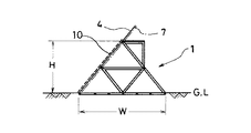
請求項1記載の発明に係る、テンションリングを水平状に配置した空気膜構造物の実施形態及び実施例を図1〜図4に示した。最外周のコンプレッションリング1は地面に固定されている。このコンプレッションリング1の構造の詳細は図3に示した。鋼管を一辺が1.5mのトラス状に組み立てた構成である。因みに該コンプレッションリング1の大きさは、半径方向の幅Wが約69m、高さHは約40mのトラスフレーム構造とされている。このコンプレッションリング1は、全体としては図1に平面図を示したように外径が約1600mの円形に構築されている。コンプレッションリング1の外周面には気密サッシ10が嵌め込まれて気密性が確保されている。
【0010】
上記した構造のコンプレッションリング1の内側には、同心円状の配置で直径が約1000mの第1のテンションリング2、及び直径が約400mの第2のテンションリング3がそれぞれ配置され、各々は放射方向に配置したワイヤーロープ(テンションロープ)4、5、6により連結され外殻フレームが形成されている(図1)。即ち、図1に示したように、コンプレッションリング1とその内側に隣合う第1のテンションリング2との間に、直径が100mm位の鋼製のワイヤーロープ4が2本を一組として内側の第1テンションリング2の位置に頂角を有する二股状の配置で各リング1、2の周方向の全長にわたり放射状に複数配置してそれぞれ連結されている。また、前記第1のテンションリング2と、更にその内側の第2のテンションリング3との間にも、前記2本を一組として内側の第1テンションリング2の位置に頂角を有するワイヤーロープ4を、放射方向に内側の第2のテンションリング3と繋ぐ1本ずつのワイヤーロープ5が配置され連結されている。更に外殻フレームの中心に位置する第2のテンションリング3の面内にも、ワイヤーロープ6がグリッド状配置に連結されている。こうして設計荷重に対して、各テンションリング2、3に連結されたワイヤーロープ4、5の張力が各テンションリングに対する内向きの力よりも外向きの力の方が大きくテンションリング2、3の応力が引っ張り応力となる外殻フレームが形成されている。但し、コンプレッションリング1、及び第1、第2のテンションリング2、3の平面形状は図示した円形の限りではない。楕円形、長円形或いは角形などの形態で実施することができる。
【0011】
上記のように構成された外殻フレームの内側に、外周をコンプレッションリング1に止着され下面を開口した偏平な袋形状をなし、例えば50〜80mmAqの内圧を作用させる空気膜7が設置されている。空気膜7には厚さ1mmの構造用四フッ化エチレン樹脂コーティングガラス繊維布が好適に使用される。ただし、空気膜7の材質及び同空気膜に作用させる内圧の大きさは前記した例に限らない。
【0012】
従って、上記の空気膜7が内圧を受けて膨張すると、図2に示したように、コンプレッションリング1と第1のテンションリング2の間、及び第1と第2のテンションリング2と3の間、並びに第2のテンションリング3の面内でそれぞれ空気膜7が膨らみを形成する超大スパンの空気膜構造物が完成する。その結果、前記コンプレッションリング1とその内側の第1テンションリング2との間を連結したワイヤーロープ4、及び同第1のテンションリング2と更に内側の第2テンションリング3との間を連結したワイヤーロープ5、並びに第2のテンションリング3の内面に連結したワイヤーロープ6にそれぞれ張力を発生して力の平衡を保つ。その際、設計上考慮した各種の外力や内圧(以下、これを設計荷重と呼ぶ)に対して、第1のテンションリング2の内外に連結されたワイヤーロープ4と5から作用する力は、同第1のテンションリング2に対しては内向きの力よりも外向きの力の方が大きくなるようにテンションリング2の位置と空気膜7の膨らみ形状とが決定されている。よって、第1のテンションリング2に発生する応力は引っ張り応力となる。
【0013】
第2のテンションリング3に対しても全く同様に、その内外に連結したワイヤーロープ5と6から受ける力は、第2のテンションリング2に対しては内向きよりも外向きの引っ張り力が大きくなるようにテンションリング3の位置と空気膜7の膨らみ形状が決定されている。よって、当該第2のテンションリング3に発生する応力も引っ張り応力となる。
【0014】
結局、外周のコンプレッションリング1にのみ圧縮応力が発生し、これ以外の第1、第2のテンションリング2、3には引っ張り応力のみが働いて空気膜構造物全体の力の平衡を保ち、ひいては構造物の形態の保持と構造的安定性を確保する。前記のようにテンションリング2、3及びワイヤーロープ4、5、6が引っ張り材として使用されることにより、材料を力学的に有効に使用することができ、超大スパン構造にしても自重量が軽減されて合成的な空気膜構造物が成立する。
【0015】
但し、空気膜7に作用する空気圧(内圧)に起因する鉛直方向上向きの力(浮力)に対して、テンションリング2、3の部分で力の釣合を保つ手段として、図2に示したように、地盤面に埋め込み設置した施設の重り12へワイヤーロープ8を結合してアンカーをとる。或いは前記浮力に余裕のある場合は、図4に示したように住宅とか雨水処理施設のような空中施設11を吊り下げ、これを更にワイヤーロープ8、9で地盤面の施設である重り12と結合して力の平衡を保つ。
【0016】
なお、空気膜7に作用する内部圧力によりテンションリング2、3に発生する位置の変化に対して補完的効力を発揮するダンパー(図示は省略)を装備して、多様な荷重に対する構造的安定性を高める構成で実施することもできる。
上述の構成により、空気膜7に作用する内部圧力を外殻フレームが拘束して全体に均衡を保つ柔軟なシェル構造を形成するから、最大外径が1600m以上にも達する超大スパンの空気膜構造物を、形態上及び構造上の安定性を確保して実現することができる。また、コンプレッションリング1及びテンションリング2及び3の直径、個数等を変更することにより、様々な形状及び規模の空気膜構造物を実現することができる。
【0017】
【本発明が奏する効果】
この発明に係るテンションリングを水平状に配置した空気膜構造物は、最外周のコンプレッションリングとその内側の複数のテンションリング及びこれらを放射方向に連結したワイヤーロープとの組み合わせによる外殻フレームを親ケーブルと子ケーブルのネットワークとして形成したので、最大外径が約1600m以上、地上の最高部位が約200m以上にも達する巨大空間を容易に創出することができる。しかも地震や風荷重に対する形態の保持、構造的安定を保つことができ、超大スパンの建築物として適性を有する空気膜構造体を提供する。
【図面の簡単な説明】
【図1】空気膜構造物の平面図である。
【図2】図1のA−A’矢視の拡大断面図である。
【図3】コンプレッションリングの拡大図である。
【図4】テンションリングを下向きにアンカーする手段の説明図である。
【符号の説明】
1 コンプレッションリング
2 テンションリング
3 テンションリング
4 ワイヤーロープ
5 ワイヤーロープ
6 ワイヤーロープ
7 空気膜[0001]
BACKGROUND OF THE INVENTION
The present invention creates a huge space with a very large span with a maximum outer diameter of about 1600 m and the highest part on the ground of about 200 m, and the inside is a closed city, factory, office, farm, stadium, or these In particular, the present invention relates to an air membrane structure in which a plurality of tension rings are horizontally arranged.
[0002]
[Prior art]
Conventionally, since a large space that is difficult to put into practical use with other structures is also possible with an air film structure, a dome-shaped air film structure that creates a huge space has been proposed.
Japanese Patent Application Laid-Open No. 63-165661 discloses an air membrane structure in which a structural material such as a tensile material that imparts a reaction force to the membrane material is improved.
[0003]
[Problems to be solved by the present invention]
There are many conventional air film structures, but there is no super-span air film structure that is horizontally wide and flat enough to build a closed urban area. The reason for this is that, in the conventional technology, the retention and structural stability of the air membrane structure depend on the internal pressure acting on the air membrane, but a single network such as a reinforcing wire rope attached to the air membrane is used. There are only. Therefore, if an air membrane structure is constructed to create a large space in the horizontal direction, the stress that the wire rope bears will increase, and the weight of the air rope will increase and the internal pressure of the air membrane must be increased. In that case, the strength of the air membrane reinforcement must be strengthened, so it is virtually impossible to build an ultra-span air membrane structure with a maximum outer diameter of over 1600 m. It is considered.
[0004]
An object of the present invention is to provide an outer shell frame formed of an outermost compression ring, a plurality of tension rings arranged on the inner side thereof, and a wire rope connected in a radial direction therebetween as a network of a parent cable and a child cable. The object is to provide an air film structure in which tension rings are horizontally arranged to create a huge space having a maximum outer diameter of about 1600 m or more and a maximum ground part of about 200 m or more.
[0005]
The next object of the present invention is to maintain the form and structural stability against earthquakes and wind loads, and as a large span building, for example, a closed city area, factory, farm, office district, or a combination of these It is to provide an air membrane structure with a very large span that has utility as a facility.
[0006]
[Means for Solving the Problems]
As means for solving the problems of the prior art, an air film structure in which tension rings according to the invention described in claim 1 are horizontally arranged is
A plurality of
Inside the shell frame, and to the air film is secured to the compression ring, such a bag-shaped bottom surface is open there is placed the internal pressure is allowed to act on the outer circumference,
The tension ring portion, characterized in that the anchor according to the vertical direction of the heavy Ri or wire rope Ru mated force is installed.
[0009]
Embodiments and Examples of the Invention
1 to 4 show an embodiment and an example of an air film structure in which tension rings are horizontally arranged according to the invention described in claim 1 . The outermost compression ring 1 is fixed to the ground. The details of the structure of the compression ring 1 are shown in FIG. It is the structure which assembled the steel pipe in the truss shape where one side is 1.5m. Incidentally, the size of the compression ring 1 is a truss frame structure having a radial width W of about 69 m and a height H of about 40 m. The compression ring 1 as a whole is constructed in a circular shape having an outer diameter of about 1600 m as shown in the plan view of FIG. An
[0010]
Inside the compression ring 1 having the above-described structure, a
[0011]
Inside the outer shell frame configured as described above, an
[0012]
Therefore, when the
[0013]
Exactly the same as for the
[0014]
Eventually, compressive stress is generated only in the outer compression ring 1, and only the tensile stress acts on the other first and second tension rings 2 and 3 to maintain the balance of the force of the entire air film structure. ensure retention and structural stability of the form of the structure. As described above, the tension rings 2 and 3 and the
[0015]
However, as shown in FIG. 2, as means for keeping the balance of force at the portions of the tension rings 2 and 3 against the upward force (buoyancy) caused by the air pressure (internal pressure) acting on the
[0016]
It is equipped with a damper (not shown) that exhibits complementary effects against changes in the position generated in the tension rings 2 and 3 due to internal pressure acting on the
With the above-described configuration, the inner shell acting on the
[0017]
[Effects of the present invention]
The air membrane structure in which the tension rings according to the present invention are horizontally arranged has an outer shell frame formed of a combination of an outermost compression ring, a plurality of tension rings on the inner side thereof, and a wire rope connecting them radially. Since it is formed as a network of cables and child cables, it is possible to easily create a huge space where the maximum outer diameter is about 1600 m or more and the highest part on the ground is about 200 m or more. In addition, it is possible to maintain the form and structural stability against earthquakes and wind loads, and to provide an air film structure suitable as a super-span building.
[Brief description of the drawings]
FIG. 1 is a plan view of an air membrane structure.
FIG. 2 is an enlarged cross-sectional view taken along the line AA ′ in FIG.
FIG. 3 is an enlarged view of a compression ring.
FIG. 4 is an explanatory diagram of a means for anchoring a tension ring downward.
[Explanation of symbols]
1
Claims (1)
前記外殻フレームの内側に、外周をコンプレッションリングへ止着されて下面が開口した袋形状をなす空気膜が設置され内圧が作用させられており、
テンションリング部分には、鉛直方向の力を釣り合わせる重り又はワイヤーロープによるアンカーが設置されていることを特徴とする、テンションリングを水平状に配置した空気膜構造物。A plurality of tensioning rings fixed to the shape of the compression ring and concentrically to approximate to this was a small on the ground is arranged, and the outermost compression ring with a set of two between its inner tension ring inner A plurality of bifurcated wire ropes having apex angles at the positions of the tension rings are arranged radially over the entire circumferential length of each ring, and the two are connected between the tension ring adjacent to the inside and the tension ring. A plurality of wire ropes are arranged over the entire length in the circumferential direction of each ring in a radial arrangement from the position of the apex angle of the wire rope to the inner tension ring , and also in the center of the tension ring surface by connecting the wire rope arranged radially with respect to the design load, which is connected to the tension ring Wye Tension Ropu outer shell frame is larger stress of the tension ring tensile stress toward the inward force outward force than is formed for each tension ring,
Inside the shell frame, and to the air film is secured to the compression ring, such a bag-shaped bottom surface is open there is placed the internal pressure is allowed to act on the outer circumference,
The tension ring portion, characterized in that the anchor is installed by vertical heavy Ri or wire rope Ru mated force, air membrane structure arranged with tension ring horizontally.
Priority Applications (1)
| Application Number | Priority Date | Filing Date | Title |
|---|---|---|---|
| JP09452898A JP3728552B2 (en) | 1998-04-07 | 1998-04-07 | Air membrane structure with tension rings arranged horizontally |
Applications Claiming Priority (1)
| Application Number | Priority Date | Filing Date | Title |
|---|---|---|---|
| JP09452898A JP3728552B2 (en) | 1998-04-07 | 1998-04-07 | Air membrane structure with tension rings arranged horizontally |
Publications (2)
| Publication Number | Publication Date |
|---|---|
| JPH11293961A JPH11293961A (en) | 1999-10-26 |
| JP3728552B2 true JP3728552B2 (en) | 2005-12-21 |
Family
ID=14112841
Family Applications (1)
| Application Number | Title | Priority Date | Filing Date |
|---|---|---|---|
| JP09452898A Expired - Fee Related JP3728552B2 (en) | 1998-04-07 | 1998-04-07 | Air membrane structure with tension rings arranged horizontally |
Country Status (1)
| Country | Link |
|---|---|
| JP (1) | JP3728552B2 (en) |
Families Citing this family (1)
| Publication number | Priority date | Publication date | Assignee | Title |
|---|---|---|---|---|
| CN102261128B (en) * | 2011-05-10 | 2014-07-30 | 唐戍鸣 | Node type gas net rack structure |
-
1998
- 1998-04-07 JP JP09452898A patent/JP3728552B2/en not_active Expired - Fee Related
Also Published As
| Publication number | Publication date |
|---|---|
| JPH11293961A (en) | 1999-10-26 |
Similar Documents
| Publication | Publication Date | Title |
|---|---|---|
| CN100532750C (en) | Cord string branch dome | |
| US3744191A (en) | Large air supported structures | |
| CN107539434B (en) | Offshore wind generating set and floating type foundation thereof | |
| WO2013189275A1 (en) | Asymmetrical open type integral tension cable membrane structure and method for construction and design therefor | |
| CN114687450B (en) | Spoke type cable-bearing crossed grid semi-rigid tension structure system | |
| CN111075023A (en) | Spoke type single-layer and double-layer mixed cable net structure | |
| CN112814248A (en) | Spoke type wave cable membrane structure roof with three-dimensional outer ring truss | |
| CN105888065A (en) | Straining beam cable rod dome structure and construction method thereof | |
| CN211691069U (en) | Installation and displacement monitoring structure of spoke type beam string | |
| CN101260704A (en) | Partial double-layer tensioned string spherical reticulated shell | |
| WO2006104888A1 (en) | Tether system for balloon ride | |
| JP3728552B2 (en) | Air membrane structure with tension rings arranged horizontally | |
| CN213539909U (en) | Inflatable beam | |
| JPH0520536B2 (en) | ||
| CN119332868B (en) | Spoke type cable-supporting grid roof and anti-tensioning construction method thereof | |
| JPH11210083A (en) | Steel framed dome structure to be reinforced by cables | |
| CA1037272A (en) | Industrial cooling tower | |
| CN201024561Y (en) | Suspension Dome | |
| CN216641106U (en) | Spoke type wave cable membrane structure roof with three-dimensional outer ring truss | |
| JP2022144489A (en) | roof support structure | |
| US4578908A (en) | Fabric roof structure | |
| CN111677175A (en) | Open type saddle-shaped spoke type tensioning structure | |
| CN214006199U (en) | Cable net air film type temporary roof | |
| US4047335A (en) | Pneumatic load-supporting structures | |
| CN211548064U (en) | Spoke type single-layer and double-layer mixed cable net structure |
Legal Events
| Date | Code | Title | Description |
|---|---|---|---|
| A977 | Report on retrieval |
Free format text: JAPANESE INTERMEDIATE CODE: A971007 Effective date: 20050222 |
|
| A131 | Notification of reasons for refusal |
Free format text: JAPANESE INTERMEDIATE CODE: A131 Effective date: 20050405 |
|
| A521 | Written amendment |
Free format text: JAPANESE INTERMEDIATE CODE: A523 Effective date: 20050602 |
|
| TRDD | Decision of grant or rejection written | ||
| A01 | Written decision to grant a patent or to grant a registration (utility model) |
Free format text: JAPANESE INTERMEDIATE CODE: A01 Effective date: 20050822 |
|
| A61 | First payment of annual fees (during grant procedure) |
Free format text: JAPANESE INTERMEDIATE CODE: A61 Effective date: 20050915 |
|
| R150 | Certificate of patent or registration of utility model |
Free format text: JAPANESE INTERMEDIATE CODE: R150 |
|
| FPAY | Renewal fee payment (event date is renewal date of database) |
Free format text: PAYMENT UNTIL: 20091014 Year of fee payment: 4 |
|
| FPAY | Renewal fee payment (event date is renewal date of database) |
Free format text: PAYMENT UNTIL: 20101014 Year of fee payment: 5 |
|
| LAPS | Cancellation because of no payment of annual fees |