JP3728541B2 - Fabric edge curl straightening device and sewing machine - Google Patents
Fabric edge curl straightening device and sewing machine Download PDFInfo
- Publication number
- JP3728541B2 JP3728541B2 JP2001345078A JP2001345078A JP3728541B2 JP 3728541 B2 JP3728541 B2 JP 3728541B2 JP 2001345078 A JP2001345078 A JP 2001345078A JP 2001345078 A JP2001345078 A JP 2001345078A JP 3728541 B2 JP3728541 B2 JP 3728541B2
- Authority
- JP
- Japan
- Prior art keywords
- curl
- fabric
- needle drop
- edge
- drop position
- Prior art date
- Legal status (The legal status is an assumption and is not a legal conclusion. Google has not performed a legal analysis and makes no representation as to the accuracy of the status listed.)
- Expired - Fee Related
Links
Images


Description
【0001】
【発明の属する技術分野】
本発明は、裾引き縫いの実施に当り、生地の裏側に折り重ねて縫い付けられる生地端に生じている外カールを針落ち位置の前側にて矯正する生地端カール矯正装置、及びこれを備えるミシンに関する。
【0002】
【従来の技術】
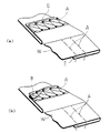
Tシャツ等の裾部処理として行われる裾引き縫いは、図5(a)に示す如く、生地Wの端縁Eを所定幅に亘って裏側に折り重ね、この端縁Eの近傍を前記生地Wの表側から縫い付ける縫製処理である。このような裾引き縫いは、従来一般的には、偏平縫いミシン又は二重環縫いミシンを用い、縫製作業者の手作業により生地の端縁を折り返し、この折り返し状態を保って針落ち位置に送り込むことにより行われている。図5には、二重環縫いによる縫い目Aが形成されている。
【0003】
しかしながら、以上の如き手作業による裾引き縫いにおいては、針落ち位置前にて折り返し幅を調整し、この折り返し幅を維持して針落ち位置に送り込むために繊細な手加減を必要とし、良質な縫いを安定して実現するためには、縫製作業者に高度の熟練が要求されるという問題があった。
【0004】
このような事情により従来から、生地Wの折り返し端縁Eをガイドするガイド手段、生地Wの裏側に折り返された端縁Eを所定幅に切断すべく針落ち位置前に出没するメス等、折り返し幅の調整を補助する補助手段を備えたミシンが種々提案されている。
【0005】
【発明が解決しようとする課題】
ところが、以上の如き補助手段を備えたミシンを用いて裾引き縫いを行ったとしても、例えば、縫製対象となる生地Wが、ニット生地等の巻きぐせがつき易い生地である場合、針落ち位置に送り込まれる生地Wの折り返し端縁が夫々の表面側又は裏面側にカールし、このカール部が端縁Eの外側又は内側に折り返された状態で縫着される虞れがあった。
【0006】
図5(b)には、カール部の縫着がなされた状態が示されている。前記カール部の縫着部分は、前記端縁Eの一部が折り返された状態で生じ、特に、前記カール部が生地Wの表面側にカールした外カールである場合、図示の如く端縁Eの外側に折り返された縫着不良部Bが生成され、得られた縫製品の品質を大きく損なうという問題がある。
【0007】
以上の如き外カール部の縫着防止は、前述した折り返し幅の調整と共に、作業者の手作業により、針落ち位置の前にて前記外カール部を引き延ばして矯正することによりなされており、この矯正に多大の手間を要するという問題があり、特に、前記生地Wが、ニット生地等の伸縮性に富む生地である場合、これらの伸縮を伴うことなく前記カールを矯正するために高度の熟練を要するという問題があった。
【0008】
特開平6-254273号公報には、このように裾引き縫いにおいて、生地の裏側に折り重ねた端縁に生じている外カールの矯正を図った装置が開示されている。この装置は、針落ち位置の前側に生地の裏面に沿ってエアを吹き出す吹き出し口を配し、前記端縁に生じている外カール部を前記エアの流れにより伸長させて針落ち位置に送り込む構成としたものである。
【0009】
しかしながらこの構成においては、エアの吹き出し口を針落ち位置の直前に設定することが難しく、前記エアの吹き付けにより伸長せしめられた外カール部が針落ち位置への到達前に復元し、良好な縫製がなされない虞れがある。また前記吹き出し口にエアを供給するためのエア源を含めた全体構成が複雑となり、前記エア源を備えていない小規模の縫製工場での採用が難しいという問題があった。
【0010】
本発明は斯かる事情に鑑みてなされたものであり、生地の裏側に折り返されて縫製される生地端の外カール部を針落ち位置の直前位置にて確実に矯正することができ、外カール部の縫い付けによる縫製不良の発生を、簡素な構成により有効に防止して、良質な裾引き縫いを、熟練を要することなく安定して行わせ得る生地端カール矯正装置、及びこれを備えるミシンを提供することを目的とする。
【0011】
【課題を解決するための手段】
本発明の第1発明に係る生地端カール矯正装置は、裾引き縫いを行うミシンに装備され、該ミシンの針落ち位置に送り込まれる生地の折り返し端縁に生じている外カール部を、前記針落ち位置の前位置にて矯正する生地端カール矯正装置において、前記生地の折り返し部を挾持し、前記針落ち位置への送りに伴って前記生地の裏側に折り重ねるガイド板と、該ガイド板の後側に連設され、前記外カール部を受容するカール受容部と、該カール受容部の後側から前記針落ち位置に向けて突設され、前記カール受容部から送り出される外カール部に当接し、該外カール部を前記生地の裏面に沿わせるべく、前記針落ち位置への送り込みに伴って引き起す生地端ガイドとを備えることを特徴とする。
【0012】
本発明においては、生地の裏面に折り返された端縁に生じている外カール部を、ガイド板の作用によりカール受容部に受容させ、該カール受容部により所定の姿勢に整えて送り出し、該カール受容部の後側に突設された生地端ガイドの作用により引き起し、生地の裏面に沿わせて針落ち位置に送り込む。
【0013】
また本発明の第2発明に係る生地端カール矯正装置は、第1発明におけるカール受容部が、前部開口に連続し後方に向けて幅を減じる導入溝と、該導入溝の後側に幅調整が可能に連設され、前記外カール部を起立姿勢に保持する保持溝とを備えることを特徴とする。
【0014】
本発明においては、カール受容部を後側に向けて幅を減じる導入溝と、該導入溝の後側に連設された保持溝とにより構成し、導入溝内に外カール部を確実に受容し、幅の減少により姿勢を矯正しつつ保持溝に導入して、該保持溝の作用により起立姿勢に保って送り出し、後側の生地端ガイドに確実に受け渡す。
【0015】
更に本発明の第3発明に係る生地端カール矯正装置は、第1又は第2発明における生地端ガイドが、前記カール受容部の後側への突出長さの増減調整が可能に取り付けられた線材により構成してあることを特徴とする。
【0016】
本発明においては、細径でありながら高剛性を有するピアノ線等の線材により生地端ガイドを構成し、針落ち位置の近傍までの突出を可能として、外カール部を生地の裏面に沿わせて矯正された状態で針落ち位置に送り込む。
【0017】
また本発明に係るミシンは、針落ち位置の前位置に、該針落ち位置に送り込まれる生地の折り返し端縁に生じている外カール部を矯正する生地端カール矯正装置を備えるミシンにおいて、前記生地端カール矯正装置は、前記生地の折り返し部を挾持し、前記針落ち位置への送りに伴って前記生地の裏側に折り重ねるガイド板と、該ガイド板の後側に連設され、前記外カール部を受容するカール受容部と、該カール受容部の後側から前記針落ち位置に向けて突設され、前記カール受容部から送り出される外カール部に当接し、該外カール部を前記生地の裏面に沿わせるべく、前記針落ち位置への送り込みに伴って引き起す生地端ガイドとを備えることを特徴とする。
【0018】
【発明の実施の形態】
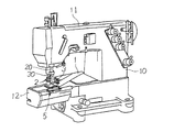
以下本発明をその実施の形態を示す図面に基づいて詳述する。図1は、本発明に係る生地端カール矯正装置を備えるミシンの外観斜視図である。
【0019】
図示のミシンは、ベッド本体1上に立設された脚部10によりその基端を支持されたミシンアーム11を備え、またベッド本体1の一側に、ミシンアーム11の下方に並行するように突設された細径の筒形ベッド12を備えてなる偏平縫いミシンである。
【0020】
ミシンアーム11の先端部には、針棒20及び押え棒30が垂下支持されており、針棒20の下端には複数本(図においては3本)の針2,2…が、また押え棒30の下端には押え金3が夫々取付けられている。筒形ベッド12の上面には、前記針2,2…及び押え金3の下位置に針板4(図2参照)が架設されており、該針板4下部の筒形ベッド12の内部には、図示しないルーパ及び送り歯が備えてある。
【0021】
前記針2,2…は、ミシンアーム11の内部に架設された図示しない上軸からの伝動により、前記針棒と共に針板4の上下を含む所定のストロークにて上下動するようになしてある。また押え金3は、所定の操作により針板4上に降下せしめられ、筒形ベッド12上に後述の如く送り込まれる生地W(図2参照)を、該針板4との間に挾持するようになしてある。
【0022】
以上の如く構成された偏平縫いミシンは、図1中に示す如く、筒形ベッド12上の前記針板4の前側に本発明に係るカール矯正装置5を備えている。図2は、カール矯正装置5の構成を針板4と共に示す斜視図である。
【0023】
本図に示す如く、筒形ベッド12上に架設された針板4の略中央部には、前述の如く上下動する針2,2…の降下時に夫々を挿通させるための複数(図においては3つ)の針落ち孔40,40…が幅方向に並べて形成され、針落ち位置が設定されており、この針落ち位置の前後及び左右両側には、前記送り歯を突出させるべく矩形に開口する送り歯孔41,41…が形成されている。なお図2には、図面の複雑化を防ぐべく、針2,2…及び押え金3の図示、並びに、針板4の左側に延びる筒形ベッド12の先端部の図示を省略してある。
【0024】
前記カール矯正装置5は、以上の如き針板4の前部を横切るように筒形ベッド12上に固定された定規台50上に取付けられた定規板51と、該定規板51上にて左右方向への位置調整可能に取付けられた下ガイド板52と、該下ガイド板52の上面に後述の如く取付けられた生地端ガイド53とを備え、更に、前記下ガイド板52の前位置に取付けられた前ガイド板54と、これらの上部に左右方向への位置調整可能に取り付けられる上ガイド板55とを備えてなる。
【0025】
図示の如く定規板51は、その左側端部を垂直に立ち上げて前後方向に延びる定規縁 51aを備えている。該定規縁 51aの上部には、前記上ガイド板55の取付け座となすべく、左方に向けて略水平に延びる座板 51bが連設されている。
【0026】
図2には、上定規板55を取り外した状態が示されている。上定規板55は、一縁に沿って固定用の長孔が形成された基部 55aと、該基部 55aの他縁に斜め外向きに突設された折り片 55bとを備える薄肉の平板であり、前記座板 51bの上面に基部 55aを重ね、前記長孔に挿通された一対の止めねじ56,56を、前記座板 51bに左右に離隔して形成された各別のねじ孔にねじ込むことにより、前記折り片 55bを右斜め前方に向けて固定されている。このように固定された上定規板55は、止めねじ56,56を緩めることにより、前記長孔をガイドとして、所定の長さ範囲内において左右に位置調整が可能である。
【0027】
図3は、下ガイド板52及び前ガイド板54の取付け状態を示す斜視図である。本図には、夫々の取付け状態を明らかとすべく、下ガイド板52の一部を破断し、また前ガイド板54を取り外して示してある。
【0028】
下ガイド板52は、定規台50上の定規板51の上面に載置したとき、後側の針板4の上面よりもやや上位置となるような厚さを有する板材であり、一縁を適幅に亘って直角に屈曲させ、前記一縁に沿って延びる固定用の長孔が形成された取付けフランジ 52aを備えている。このような下ガイド板52は、図示の如く定規板51の上面に載置され、取付けフランジ 52aの長孔に挿通された一対の止めねじ57,57の夫々を、前記定規台50の前面に左右に離隔して形成された各別のねじ孔(図示せず)にねじ込むことにより、前記上定規板55と同様に、前記長孔の長さ範囲内において左右方向の位置調整が可能に取付けられている。
【0029】
以上の取付けにより前記定規板51の定規縁 51aに対向する下ガイド板52の左側縁には、その前半部に、前右方向に向けてテーパ状に傾斜するテーパ縁 52cが設けられている。下ガイド板52の取付けは、前記テーパ縁 52cの後側に連続する部位と前記定規縁 51aとの間に適宜幅の隙間を確保して、下ガイド板52と定規板51との間に、前部に広幅の開口を有し、後方に向けて幅を減じる導入溝6aと、該導入溝6aの後側に連設された一定幅の保持溝6bとを形成するようになされている。前記保持溝6bの幅は、前記下ガイド板52の左右方向の位置調整により増減することが可能である。
【0030】
前ガイド板54は、図示の如く成形された薄肉の板材であり、その一側を前記下ガイド板52の取付けフランジ 52aの前面に止めねじ58により固定し、他側が定規板51の上面と略面一をなして左方に延びるように取付けられている。この取付けにより前記導入溝6aの前部開口近傍に位置する前ガイド板54の左端部には、斜め下方に向けて屈曲成形されたガイド片 54aが設けてある。
【0031】
一方前記生地端ガイド53は、図示の如く、適宜長さに裁断された細径の線材であり、下ガイド板52の上面に形成された溝内に埋め込み、その中途部を止めねじ59により押えて、前記保持溝6bの後側開口部の斜め後方に向けて先端を突出せしめて取付けられている。以上の如き生地端ガイド53の突出長さは、前記止めねじ59を緩め、前記溝に沿って移動させることにより、前記押え金3に干渉しない範囲において適宜に変更可能である。
【0032】
以上の如く構成されたカール矯正装置5を備えるミシンにおいて、前記上ガイド板55の折り片 55bを利用して端縁Eの近傍を所定幅に亘って裏側に折り返した生地Wを、図2中に2点鎖線により示す如く、下ガイド板52との間に挾持せしめた状態にセットし、この状態でミシンを駆動すると、針板4上に突出する送り歯の作用により前記生地Wに送りが加えられ、該針板4上の針落ち孔40,40…に降下する針2,2…と、針板4下での図示しないルーパの動作とにより、図5に示す如く裾引き縫いが行われる。
【0033】
この間、前記生地Wの端縁Eは、前ガイド板54のガイド片 54aの作用により定規板51上に導かれ、前記定規縁 51aにより折り返し長さを規制されて、略一定の折り返し幅を有して針板4上に送り込まれる。なお前記上ガイド板55は、エアシリンダ等の適宜の駆動手段の動作により、定規板51と共に左方向に退避動作させる構成とすることも可能であり、この構成によれば、前記生地Wの初期セットを容易に行わせることができる。
【0034】
カール矯正装置5は、以上の如く行われる裾引き縫いにおいて、図2に示す如く、生地Wの折り返し端縁Eに生じている外カール部Cを、該生地Wの送りに伴って段階的に矯正し、前記生地Wの裏面に良好に沿わせた状態で針落ち位置に送り込む作用をなす。
【0035】
図4は、カール矯正装置5の動作説明図であり、(a),(b),(c)の各図は、図2中のA−A,B−B,C−Cの各断面における生地Wの状態を示している。
【0036】
生地Wの端縁Eは、前述の如く、前ガイド板54の作用により定規板51の上面に導かれる。定規板51の上面には、下ガイド板52のテーパ縁 52cにより広幅に開口する導入溝6aが形成されており、前記端縁Eに生じている外カール部Cは、前記導入溝6a内に確実に受容される。
【0037】
前記導入溝6aは、後側に向けて幅を減じるように形成されており、前記外カール部Cは、生地Wの送りに伴って前記定規板51の定規縁 51aに向けて押され、端縁Eから離れた側から徐々に伸長されつつ前記導入溝6aの後側に連続する保持溝6b内に導かれ、図4(b)に示す如く、保持溝6bに起立姿勢に保持される。
【0038】
前記保持溝6bの幅は、下ガイド板52の左右位置の調整により増減調整することができ、この増減調整を、例えば、生地Wの厚さ、外カール部Cの生成状態に応じて行わせることにより、図4(b)に示す如き保持姿勢を確実に実現することができる。
【0039】
以上の如き保持溝6b内の外カール部Cは、更なる生地Wの送りにより、前記保持溝6bの後側に抜け出すが、この後側には、線材からなる生地端ガイド53が、左斜め後方に突設させてあり、前記外カール部Cは、図4(c)に示す如く、生地端ガイド53上に乗り上げ、生地Wの進行に伴って該生地Wの裏面に沿うように伸長される。
【0040】
前述の如く生地端ガイド53の突出長さは、前記押え金3に干渉しない範囲において針板4上の針落ち位置に可及的に近付けることが可能であり、生地端ガイド53により伸長された外カール部Cは、この伸長状態を保って押え金3と針板4との間に受け渡される。この結果、針落ち位置においては、図5(b)に示すような縫着不良部Bが生じる虞れが殆どなく、良好な裾引き縫いを安定して行わせることができる。
【0041】
生地端ガイド53は、前述した線材に限らず、棒材、板材等の適宜の材料にて構成することができるが、細径の線材を用いることにより、突出長さの調整を可能とした下ガイド板52の上面への固定構造を簡素に実現することができ、また、押え金3等の周辺部材との干渉を避けて針落ち位置に可及的に近付けた配置が可能となり、前述した外カール部Cの伸長動作を確実に行わせることができる。生地端ガイド53として用いる線材は、ピアノ線等、細径でありながら高剛性が有する線材を用いるのが望ましい。
【0042】
なお、生地Wの裏側に折り返された端縁Eを所定幅に切り揃えるメスを針落ち位置の前に備えるメス付きミシンにおいては、前記生地端ガイド53は、前記メスの直前に無理なく配置でき、突出長さの増減調整が実質上不要である。従って、前記生地端ガイド53を板材とし、下ガイド板52の上面に固定支持する構成とすることができ、更には、前記導入溝6a及び保持溝6bを形成する下ガイド板52の左縁部後端に生地端ガイド53を一体構成することも可能である。
【0043】
【発明の効果】
以上詳述した如く本発明の第1発明に係る生地端カール矯正装置においては、生地の裏面に折り返された端縁に生じている外カール部が、ガイド板、カール受容部及び生地端ガイドの機械的な作用により矯正され、生地の裏面に沿って針落ち位置に送り込まれるから、簡素な構成でありながら、外カール部の縫い付けによる縫製不良の発生を有効に防止することができ、良質な裾引き縫いを、熟練を要することなく安定して行わせることが可能となる。
【0044】
また本発明の第2発明に係る生地端カール矯正装置においては、カール受容部を、後側に向けて幅を減じる導入溝と、該導入溝の後側に連設された保持溝とにより構成したから、外カール部を導入溝内に確実に受容することができ、また導入溝の幅の減少により徐々に矯正される外カール部を、保持溝の作用により起立姿勢に保って送り出すことができ、生地端ガイドによる最終的なカール矯正を確実に行わせることができる。
【0045】
また本発明の第3発明に係る生地端カール矯正装置においては、生地端ガイドをカール受容部の後側への突出長さの増減調整が可能に取り付けられた線材により構成したから、針落ち位置の直前にまで近付けた配置が可能となり、外カール部の矯正を良好に行わせることができ、外カール部の縫い付けによる縫製不良の発生をより確実に防止することが可能となる。
【0046】
更に本発明に係るミシンにおいては、針落ち位置前のガイド板、カール受容部及び生地端ガイドの機械的な作用により、針落ち位置に送り込まれる生地の折り返し端縁に生じている外カール部が、生地の裏面に沿うように矯正されるから、外カール部の縫い付けによる縫製不良の発生を抑え、良質な裾引き縫いを、熟練を要することなく安定して行わせることが可能となる等、本発明は優れた効果を奏する。
【図面の簡単な説明】
【図1】本発明に係る生地端カール矯正装置を備えるミシンの外観斜視図である。
【図2】カール矯正装置の構成を針板と共に示す斜視図である。
【図3】下ガイド板及び前ガイド板の取付け状態を示す斜視図である。
【図4】カール矯正装置の動作説明図である。
【図5】裾引き縫いにおける縫製不良の説明図である。
【符号の説明】
2 針
3 押え金
4 針板
5 カール矯正装置
6a 導入溝
6b 保持溝
51 定規板
52 下ガイド板
53 生地端ガイド
54 前ガイド板
55 上ガイド板
C 外カール部
W 生地[0001]
BACKGROUND OF THE INVENTION
The present invention includes a fabric end curl correcting device that corrects an outer curl generated on a fabric end that is folded and sewn on the back side of the fabric when performing hemline stitching on the front side of the needle drop position, and the same. Regarding sewing machines.
[0002]
[Prior art]
As shown in FIG. 5 (a), the hem stitching performed as a hem processing for a T-shirt or the like is performed by folding the edge E of the fabric W over the back side over a predetermined width, and the vicinity of the edge E is the fabric. This is a sewing process for sewing from the front side of W. Conventionally, such hem-sewing is generally performed by using a flat stitch sewing machine or a double chain stitch sewing machine, and the edge of the fabric is folded back manually by a sewing manufacturer, and this folded state is maintained to a needle drop position. It is done by sending in. In FIG. 5, a seam A is formed by double chain stitching.
[0003]
However, in the above-described hem stitching by hand, the folding width is adjusted before the needle drop position, and delicate manual adjustment is required to maintain this folding width and feed it to the needle drop position. In order to stably realize the sewing machine, there is a problem that a high degree of skill is required of the sewing manufacturer.
[0004]
Due to such circumstances, the guide means for guiding the folded edge E of the fabric W, the knife that appears before and after the needle drop position to cut the edge E folded back on the back side of the fabric W to a predetermined width, etc. Various sewing machines having auxiliary means for assisting width adjustment have been proposed.
[0005]
[Problems to be solved by the invention]
However, even if the hem is sewn using the sewing machine provided with the auxiliary means as described above, for example, if the fabric W to be sewn is a fabric that is easily wound, such as a knit fabric, the needle drop position There is a possibility that the folded edge of the fabric W fed into the curl curls to the front side or the back side and is sewn in a state where the curled part is folded outside or inside the edge E.
[0006]
FIG. 5B shows a state where the curled portion is sewn. The sewn portion of the curled portion occurs when a part of the edge E is folded back. In particular, when the curled portion is an outer curl curled on the surface side of the fabric W, the edge E as shown in the figure. There is a problem in that a poorly-sewn part B that is folded outward is generated and the quality of the obtained sewing product is greatly impaired.
[0007]
The prevention of sewing of the outer curl portion as described above is performed by extending and correcting the outer curl portion in front of the needle drop position by the operator's manual operation together with the adjustment of the folding width described above. There is a problem that much labor is required for correction, and in particular, when the fabric W is a fabric having high elasticity such as a knit fabric, a high level of skill is required to correct the curl without the expansion and contraction. There was a problem that it took.
[0008]
Japanese Patent Application Laid-Open No. 6-254273 discloses an apparatus for correcting an outer curl generated at an edge folded on the back side of a cloth in hem stitching as described above. This device has a structure in which a blowout port for blowing air along the back surface of the fabric is arranged on the front side of the needle drop position, and the outer curl portion generated at the end edge is extended by the air flow and sent to the needle drop position. It is what.
[0009]
However, in this configuration, it is difficult to set the air outlet immediately before the needle drop position, and the outer curl portion extended by the air blowing is restored before reaching the needle drop position, and good sewing is performed. There is a risk that will not be made. In addition, the entire configuration including an air source for supplying air to the air outlet becomes complicated, and there is a problem that it is difficult to employ in a small-scale sewing factory not equipped with the air source.
[0010]
The present invention has been made in view of such circumstances, and the outer curl portion of the fabric end that is folded and sewn on the back side of the fabric can be reliably corrected immediately before the needle drop position. Fabric end curl correction device capable of effectively preventing occurrence of poor sewing due to sewing of parts by a simple configuration and stably performing high-quality hemline sewing without requiring skill, and a sewing machine provided with the same The purpose is to provide.
[0011]
[Means for Solving the Problems]
A fabric edge curl correcting device according to a first aspect of the present invention is provided in a sewing machine that performs hem stitching, and an outer curl portion generated at a folded end edge of a fabric fed to a needle drop position of the sewing machine is provided on the needle. In the fabric edge curl correction device that corrects at the front position of the drop position, a guide plate that holds the folded portion of the fabric and folds back to the back side of the fabric in accordance with feeding to the needle drop position, A curl receiving portion that is connected to the rear side and receives the outer curl portion, and a curl receiving portion that protrudes from the rear side of the curl receiving portion toward the needle drop position and is fed out from the curl receiving portion. A cloth end guide that is brought into contact with the needle drop position to bring the outer curl portion into contact with the back surface of the cloth.
[0012]
In the present invention, the outer curl portion generated at the edge folded back on the back surface of the fabric is received by the curl receiving portion by the action of the guide plate, adjusted to a predetermined posture by the curl receiving portion, and sent out. It is raised by the action of the dough end guide projecting on the rear side of the receiving portion, and fed to the needle drop position along the back side of the dough.
[0013]
In the fabric edge curl correcting device according to the second invention of the present invention, the curl receiving portion in the first invention has an introduction groove that continues to the front opening and decreases in width toward the rear, and a width on the rear side of the introduction groove. A holding groove that is continuously provided so as to be adjustable and that holds the outer curl portion in an upright posture.
[0014]
In the present invention, the curl receiving portion is configured by an introduction groove that reduces the width toward the rear side and a holding groove that is provided continuously on the rear side of the introduction groove, and the outer curl portion is reliably received in the introduction groove. Then, it is introduced into the holding groove while the posture is corrected by reducing the width, and is sent out while being kept in an upright posture by the action of the holding groove, and reliably delivered to the rear fabric end guide.
[0015]
Furthermore, the fabric end curl correcting device according to the third aspect of the present invention is a wire rod to which the fabric end guide according to the first or second aspect is attached so as to be able to increase or decrease the protruding length of the curl receiving portion to the rear side. It is characterized by comprising.
[0016]
In the present invention, the fabric end guide is constituted by a wire rod such as a piano wire having a small diameter but high rigidity, and can be projected to the vicinity of the needle drop position, with the outer curl portion along the back surface of the fabric. Send it to the needle entry position in a corrected state.
[0017]
Further, the sewing machine according to the present invention is a sewing machine provided with a fabric end curl correcting device that corrects an outer curl portion generated at a folded edge of the fabric fed to the needle drop position at a position before the needle drop position. An end curl correction device is provided on the back side of the guide plate, which is connected to the guide plate that holds the folded portion of the fabric and folds on the back side of the fabric as it is fed to the needle drop position. A curl receiving portion that receives the curled portion, and protrudes from the rear side of the curl receiving portion toward the needle drop position, and abuts against an outer curled portion that is fed from the curl receiving portion, and A cloth edge guide that is raised along with the feeding to the needle drop position is provided to be along the back surface.
[0018]
DETAILED DESCRIPTION OF THE INVENTION
Hereinafter, the present invention will be described in detail with reference to the drawings illustrating embodiments thereof. FIG. 1 is an external perspective view of a sewing machine equipped with a fabric edge curl correcting device according to the present invention.
[0019]
The illustrated sewing machine includes a sewing machine arm 11 whose base end is supported by a
[0020]
A
[0021]
The
[0022]
As shown in FIG. 1, the flat stitch sewing machine configured as described above includes a
[0023]
As shown in the figure, a plurality of (in the figure, a plurality of) are inserted into the substantially central portion of the
[0024]
The
[0025]
As shown in the figure, the
[0026]
FIG. 2 shows a state where the
[0027]
FIG. 3 is a perspective view showing how the
[0028]
The
[0029]
The
[0030]
The
[0031]
On the other hand, as shown in the drawing, the
[0032]
In the sewing machine including the
[0033]
During this time, the edge E of the fabric W is guided onto the
[0034]
As shown in FIG. 2, the
[0035]
FIG. 4 is a diagram for explaining the operation of the
[0036]
The edge E of the fabric W is guided to the upper surface of the
[0037]
The introduction groove 6a is formed to reduce the width toward the rear side, and the outer curl portion C is pushed toward the
[0038]
The width of the holding
[0039]
The outer curled portion C in the holding
[0040]
As described above, the protruding length of the
[0041]
The
[0042]
In addition, in a sewing machine with a scalpel provided with a scalpel that trims the edge E folded back on the back side of the fabric W to a predetermined width in front of the needle drop position, the
[0043]
【The invention's effect】
As described above in detail, in the fabric end curl correcting apparatus according to the first aspect of the present invention, the outer curl portion generated on the edge folded back on the back surface of the fabric is formed by the guide plate, the curl receiving portion, and the fabric end guide. Since it is corrected by mechanical action and sent to the needle entry position along the back of the fabric, it is possible to effectively prevent the occurrence of poor sewing due to the sewing of the outer curl part, although it has a simple configuration. Therefore, it is possible to perform stable hem-stitching without requiring skill.
[0044]
In the fabric end curl correcting device according to the second aspect of the present invention, the curl receiving portion is constituted by an introduction groove that decreases in width toward the rear side, and a holding groove that is continuously provided on the rear side of the introduction groove. Therefore, the outer curl portion can be reliably received in the introduction groove, and the outer curl portion that is gradually corrected by the reduction of the width of the introduction groove can be sent out in an upright position by the action of the holding groove. And the final curl correction by the cloth edge guide can be surely performed.
[0045]
In the fabric end curl correcting device according to the third aspect of the present invention, the fabric end guide is composed of a wire rod attached so that the length of the protrusion to the rear side of the curl receiving portion can be adjusted. Therefore, the outer curl portion can be corrected well, and it is possible to more surely prevent the occurrence of poor sewing due to the sewing of the outer curl portion.
[0046]
Furthermore, in the sewing machine according to the present invention, the outer curl portion generated at the folded end edge of the fabric fed to the needle drop position is caused by the mechanical action of the guide plate, the curl receiving portion and the fabric end guide before the needle drop position. Since it is corrected along the back side of the fabric, it is possible to suppress the occurrence of poor sewing due to the stitching of the outer curl portion, and to stably perform high-quality hemline sewing without requiring skill, etc. The present invention has an excellent effect.
[Brief description of the drawings]
FIG. 1 is an external perspective view of a sewing machine equipped with a fabric edge curl correcting device according to the present invention.
FIG. 2 is a perspective view showing a configuration of a curl correction device together with a needle plate.
FIG. 3 is a perspective view showing an attachment state of a lower guide plate and a front guide plate.
FIG. 4 is an operation explanatory diagram of the curl correction apparatus.
FIG. 5 is an explanatory diagram of a sewing failure in hem sewing.
[Explanation of symbols]
2 Needle 3
6a Introduction groove
6b Holding groove
51 Ruler plate
52 Lower guide plate
53 Fabric edge guide
54 Front guide plate
55 Upper guide plate C Outer curl section W Fabric
Claims (4)
前記生地の折り返し部を挾持し、前記針落ち位置への送りに伴って前記生地の裏側に折り重ねるガイド板と、
該ガイド板の後側に連設され、前記外カール部を受容するカール受容部と、
該カール受容部の後側から前記針落ち位置に向けて突設され、前記カール受容部から送り出される外カール部に当接し、該外カール部を前記生地の裏面に沿わせるべく、前記針落ち位置への送り込みに伴って引き起す生地端ガイドと
を備えることを特徴とする生地端カール矯正装置。In the fabric edge curl correction device for correcting the outer curl portion generated at the folded end edge of the fabric fed to the needle drop position of the sewing machine that performs hem stitching at the front position of the needle drop position,
A guide plate that holds the folded portion of the fabric and folds it on the back side of the fabric as it is fed to the needle drop position;
A curl receiving portion connected to the rear side of the guide plate and receiving the outer curl portion;
Projecting from the rear side of the curl receiving portion toward the needle drop position, abuts against an outer curl portion fed out from the curl receiving portion, and the needle drop in order to keep the outer curl portion along the back surface of the fabric. A fabric end curl correction device comprising: a fabric end guide that is raised with feeding to a position.
前記生地端カール矯正装置は、
前記生地の折り返し部を挾持し、前記針落ち位置への送りに伴って前記生地の裏側に折り重ねるガイド板と、
該ガイド板の後側に連設され、前記外カール部を受容するカール受容部と、
該カール受容部の後側から前記針落ち位置に向けて突設され、前記カール受容部から送り出される外カール部に当接し、該外カール部を前記生地の裏面に沿わせるべく、前記針落ち位置への送り込みに伴って引き起す生地端ガイドと
を備えることを特徴とするミシン。In a sewing machine including a fabric end curl correction device that corrects an outer curl portion generated at a folded end edge of the fabric fed to the needle drop position at a position before the needle drop position,
The fabric edge curl correcting device is:
A guide plate that holds the folded portion of the fabric and folds it on the back side of the fabric as it is fed to the needle drop position;
A curl receiving portion connected to the rear side of the guide plate and receiving the outer curl portion;
Projecting from the rear side of the curl receiving portion toward the needle drop position, abuts against an outer curl portion fed out from the curl receiving portion, and the needle drop in order to keep the outer curl portion along the back surface of the fabric. A sewing machine comprising: a cloth edge guide that is raised with feeding to a position.
Priority Applications (1)
| Application Number | Priority Date | Filing Date | Title |
|---|---|---|---|
| JP2001345078A JP3728541B2 (en) | 2001-11-09 | 2001-11-09 | Fabric edge curl straightening device and sewing machine |
Applications Claiming Priority (1)
| Application Number | Priority Date | Filing Date | Title |
|---|---|---|---|
| JP2001345078A JP3728541B2 (en) | 2001-11-09 | 2001-11-09 | Fabric edge curl straightening device and sewing machine |
Publications (2)
| Publication Number | Publication Date |
|---|---|
| JP2003144781A JP2003144781A (en) | 2003-05-20 |
| JP3728541B2 true JP3728541B2 (en) | 2005-12-21 |
Family
ID=19158485
Family Applications (1)
| Application Number | Title | Priority Date | Filing Date |
|---|---|---|---|
| JP2001345078A Expired - Fee Related JP3728541B2 (en) | 2001-11-09 | 2001-11-09 | Fabric edge curl straightening device and sewing machine |
Country Status (1)
| Country | Link |
|---|---|
| JP (1) | JP3728541B2 (en) |
Families Citing this family (4)
| Publication number | Priority date | Publication date | Assignee | Title |
|---|---|---|---|---|
| JP5429709B2 (en) * | 2009-03-03 | 2014-02-26 | ヤマトミシン製造株式会社 | Sewing machine folding back guide device |
| JP5967540B2 (en) * | 2012-09-18 | 2016-08-10 | ヤマトミシン製造株式会社 | Hem stitch machine |
| JP6410145B2 (en) * | 2014-12-19 | 2018-10-24 | ヤマトミシン製造株式会社 | Hem stitch sewing machine |
| CN114892349A (en) * | 2022-04-11 | 2022-08-12 | 中山市蝶安芬内衣有限公司 | A guide fifty percent discount device for sewing machine |
-
2001
- 2001-11-09 JP JP2001345078A patent/JP3728541B2/en not_active Expired - Fee Related
Also Published As
| Publication number | Publication date |
|---|---|
| JP2003144781A (en) | 2003-05-20 |
Similar Documents
| Publication | Publication Date | Title |
|---|---|---|
| JP4725863B2 (en) | Presser foot and sewing machine | |
| JP5984093B2 (en) | Fabric edge curl straightener | |
| JP5429709B2 (en) | Sewing machine folding back guide device | |
| JP3728541B2 (en) | Fabric edge curl straightening device and sewing machine | |
| JP6410145B2 (en) | Hem stitch sewing machine | |
| JP4799946B2 (en) | Sewing sewing machine | |
| JP4769536B2 (en) | Sewing machine with buttons | |
| JPH10235054A (en) | Cloth folded back guide device of sewing machine | |
| JP2878655B2 (en) | Jig for edging and sewing machine with edging jig | |
| US5960729A (en) | Pressing member with air ejector for a sewing machine | |
| JP3991309B2 (en) | Sewing machine presser foot | |
| JPH01101996A (en) | Multi-functional sewing machine | |
| KR100960395B1 (en) | Wrapping assembly for sewing machine | |
| JP4158083B2 (en) | Sewing machine with a knife | |
| US5524563A (en) | system for automatically sewing an imitation cuff | |
| JP2001000767A (en) | Corrector for cloth end curl | |
| TW202045791A (en) | Round fabric hem sewing machine | |
| JP3908051B2 (en) | Sewing cloth guide structure | |
| JP2548258Y2 (en) | Automatic lip stitching device | |
| JP4066049B2 (en) | Automatic curtain sewing machine | |
| JPH0727471U (en) | Sewing machine presser for fabric winding | |
| JPH0662982U (en) | A edging jig and a sewing machine equipped with the edging jig | |
| JPH0249687A (en) | Hem edge guide of sewing machine | |
| US2918026A (en) | Plait forming attachments for sewing machines | |
| JPH11207068A (en) | Presser for sewing machine |
Legal Events
| Date | Code | Title | Description |
|---|---|---|---|
| A621 | Written request for application examination |
Free format text: JAPANESE INTERMEDIATE CODE: A621 Effective date: 20040927 |
|
| A977 | Report on retrieval |
Free format text: JAPANESE INTERMEDIATE CODE: A971007 Effective date: 20050825 |
|
| TRDD | Decision of grant or rejection written | ||
| A01 | Written decision to grant a patent or to grant a registration (utility model) |
Free format text: JAPANESE INTERMEDIATE CODE: A01 Effective date: 20050830 |
|
| A61 | First payment of annual fees (during grant procedure) |
Free format text: JAPANESE INTERMEDIATE CODE: A61 Effective date: 20050914 |
|
| R150 | Certificate of patent or registration of utility model |
Free format text: JAPANESE INTERMEDIATE CODE: R150 |
|
| FPAY | Renewal fee payment (event date is renewal date of database) |
Free format text: PAYMENT UNTIL: 20081014 Year of fee payment: 3 |
|
| FPAY | Renewal fee payment (event date is renewal date of database) |
Free format text: PAYMENT UNTIL: 20091014 Year of fee payment: 4 |
|
| FPAY | Renewal fee payment (event date is renewal date of database) |
Free format text: PAYMENT UNTIL: 20091014 Year of fee payment: 4 |
|
| FPAY | Renewal fee payment (event date is renewal date of database) |
Free format text: PAYMENT UNTIL: 20101014 Year of fee payment: 5 |
|
| FPAY | Renewal fee payment (event date is renewal date of database) |
Free format text: PAYMENT UNTIL: 20111014 Year of fee payment: 6 |
|
| FPAY | Renewal fee payment (event date is renewal date of database) |
Free format text: PAYMENT UNTIL: 20121014 Year of fee payment: 7 |
|
| FPAY | Renewal fee payment (event date is renewal date of database) |
Free format text: PAYMENT UNTIL: 20131014 Year of fee payment: 8 |
|
| R250 | Receipt of annual fees |
Free format text: JAPANESE INTERMEDIATE CODE: R250 |
|
| LAPS | Cancellation because of no payment of annual fees |