JP3728237B2 - Injection foam mold - Google Patents
Injection foam mold Download PDFInfo
- Publication number
- JP3728237B2 JP3728237B2 JP2001344802A JP2001344802A JP3728237B2 JP 3728237 B2 JP3728237 B2 JP 3728237B2 JP 2001344802 A JP2001344802 A JP 2001344802A JP 2001344802 A JP2001344802 A JP 2001344802A JP 3728237 B2 JP3728237 B2 JP 3728237B2
- Authority
- JP
- Japan
- Prior art keywords
- mold
- slide
- movable
- cavity
- injection
- Prior art date
- Legal status (The legal status is an assumption and is not a legal conclusion. Google has not performed a legal analysis and makes no representation as to the accuracy of the status listed.)
- Expired - Fee Related
Links
Images


Landscapes
- Moulds For Moulding Plastics Or The Like (AREA)
- Molding Of Porous Articles (AREA)
Description
【0001】
【発明の属する技術分野】
本発明は、射出発泡成形用金型に関する。
【0002】
【従来の技術】
金型のキャビティ内に発泡剤を含む樹脂を射出した後、可動型と固定型とをパーティングライン部分で閉じた状態を保ちながら金型内でキャビティの型面を構成するスライド型をキャビティ空間が拡大する方向にスライドさせて、樹脂を発泡させて、金型の型面に沿ってスキン層が形成され、内部に発泡層が形成された発泡成形体を製造する射出発泡成形方法がすでに提案されている(特開平7−88878号公報、特開平8−90620号公報等参照)。
【0003】
即ち、この成形方法によって得られた成形体は、成形体内部が発泡しており、断熱性に優れるとともに軽量であるだけでなく、表面にスキン層を備えているので、防汚性、剛性、耐摩耗性に優れたものとなるという利点を備えている。
【0004】
ところで、射出成形の場合、樹脂を射出成形機から金型キャビティ内に射出する際に、キャビティ壁面にかなり大きな力が加わる。したがって、大型の成形品を得るような場合、射出時にスライド型の後方にスライド空間が有るような構造にすると、射出樹脂圧で各スライド型がずれ動き、射出完了後スライド型を後退させてキャビティを拡開して樹脂を発泡させても、1ショットごとに発泡状態の異なる成形品が形成される恐れがある。一方、上記問題を解決するために各スライド型を作動させる油圧機構などを大きなものにすると、金型構造が複雑になりメンテナンス性が悪くなるとともに、金型コストがかかるという問題がある。
【0005】
【発明が解決しようとする課題】
本発明は、このような事情に鑑みて、簡単な金型構造で、スライド型が、射出時の射出樹脂圧でずれ動いて成形不良が発生したりすることのない射出発泡成形用金型を提供することを目的としている。
【0006】
【課題を解決するための手段】
このような目的を達成するために、本発明の請求項1に記載の射出発泡成形用金型(以下、「請求項1の金型」と記す)は、キャビティ内に発泡剤含有溶融樹脂が射出され、射出完了後、キャビティの型面を形成するスライド型が油圧シリンダによってキャビティ拡開方向にスライドさせられて、樹脂をキャビティ内で発泡させるようになっている射出発泡成形用金型において、キャビティ空間が極小状態になる位置に配置されたスライド型に前記油圧シリンダを介さず型閉め圧が伝達され、型閉め圧によってスライド型の射出圧による位置ずれが防止されるとともに、型閉め圧が解除された状態で前記スライド型が、前記油圧シリンダを介して、キャビティ空間が拡大する方向にスライド可能となされている構成とした。
【0007】
本発明の請求項2に記載の射出発泡成形用金型(以下、「請求項2の金型」と記す)は、請求項1の金型において、可動型が、可動型本体と、この可動型本体に対して分離状態で可動可能な成形機取付板とを備える分割構造を有するとともに、少なくとも成形機取付板が型開放方向へ移動時に可動型本体と固定型とを閉じた状態にロックするロック手段を備えている構成とした。
【0008】
本発明の請求項3に記載の射出発泡成形用金型(以下、「請求項3の金型」と記す)は、請求項1または請求項2の金型において、複数のスライド型を有し、これらのスライド型が1つの油圧シリンダによって連動してスライド駆動する構成とした。
【0009】
【発明の実施の形態】
以下に、本発明を、その実施の形態をあらわす図を参照しつつ詳しく説明する。ただし、本発明は、図示の実施形態に限定されるものではなく、本発明の主旨を逸脱しない範囲の設計変更を含むものである。
図1〜図7は本発明の射出発泡成形用金型の1つの実施の形態をあらわしている。
【0010】
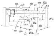
図1および図2に示すように、この金型200は、固定型210と可動型220との閉合により矩形の箱型をしたキャビティKが形成されるようになっている。
可動型220は、可動型本体222と、この可動型本体222に対して分離状態で可動可能な成形機取付板221とを備える分割構造を有するとともに、底用スライド型223と、4つの側壁用スライド型(図では2つしか表れていない。)224と、スライド型位置規制手段としてのスライド型押さえブロック225と、駆動手段としての油圧シリンダ226と、ロック開閉機構250と、成形機取付板221の動作伝達機構260が設けられている。
【0011】
図2に示すように、スライド型押さえブロック225は、ブロック本体225aと、スライド脚部225bと、側面抑え脚部225cと、底用スライド型抑え脚部225dとを備え、油圧シリンダ226によって可動型本体222に対して固定型210方向に進退自在になっている。
スライド脚部225bは、図3に示すように、その先端部の側壁用スライド型224側の壁面がテーパ面225eになっていて、このテーパ面225eが側壁用スライド型224のテーパ状の外壁面224cにスライド自在に当接している。そして、型閉合状態で、スライド脚部225bが、射出時の側壁用スライド型224にかかる射出圧を受けて、側壁用スライド型224がキャビティ拡大方向へスライドしないように側壁用スライド型224を支持するようになっている。
【0012】
側面抑え脚部225cは、図2および図3に示すように、各側壁用スライド型224の両側面にスライド自在に当接して、側壁用スライド型224の側面に設けられたガイドローラ224aが臨むガイド溝225fを側壁用スライド型224の当接面に備えている。
ガイド溝225fは、スライド脚部225bのテーパ面225eと略平行になるように、可動型220の開閉方向に対して傾斜している。
【0013】
すなわち、側面抑え脚部225cは、ブロック本体225aが油圧シリンダ226によって可動型本体222から離れる方向に動かされると、側壁用スライド型224の側面への当接状態を保ちながらブロック本体225aとともに可動型本体222から離れる方向に動くようになっている。そして、ガイドローラ224aをガイド溝225fの外側壁面で係止し、発泡圧による側壁用スライド型224のキャビティKを拡開する方向の動きをガイドローラ224aによって規制しながら、ガイド溝225fのテーパによって側壁用スライド型224をキャビティ拡大方向にスライドさせるようになっている。
【0014】
底用スライド型抑え脚部225dは、型閉め時に底用スライド型223の固定型210から離れる方向への動きを抑えるようになっている。
底用スライド型223は、リンク227を介して各側壁用スライド型224と接続されていて、図2(c)に示すように、側壁用スライド型224がキャビティKの壁面を後退させる方向にスライドすると同時にリンク227によって、キャビティKの壁面を後退させる方向、すなわち固定型210から遠ざかる方向にスライドするようになっている。
【0015】
ロック開閉機構250は、図1,図4および図5に示すように、回動ロック部材251と、2つの係止部材252と、ロック解除手段253とを備えている。
回動ロック部材251は、一方に略コ字形をしたロック部251aを有し、他方に端部にテーパ部251bが設けられたスライド部251cを備えていて、中間部に設けられた軸270によって可動型本体222の側面に、回動自在に取り付けられている。
【0016】
係止部材252は、固定型210の側面および可動型本体222の側面から突出するようにそれぞれ取り付けられていて、固定型210と可動型本体222が閉合状態のとき、図1に示すように、ロック部251aの内側の両係止部材252が入り込み、固定型210側の係止部材252にロック部251aの先端側内壁面が係止され、可動型本体222側の係止部材252にロック部の後端側内壁面が係止されるようになっている。
【0017】
ロック解除手段253は、成形機取付板221に固定されていて、回動ロック部材251のスライド部251cがスライド自在に内部に入り込み、固定型210側で開口するレール溝253aを有し、このレール溝253aは、スライド部251cのテーパ部251bとほぼ同じ傾斜角度で屈曲する屈曲溝部253bを有している。
【0018】
つぎに、このロック開閉機構250の動作を図1,図4および図5を用いて詳しく説明する。
すなわち、このロック開閉機構250は、図1に示すように、固定型210と可動型220とを型閉めした状態のとき、回動ロック部材251のロック部251a内に固定型210および可動型本体222に設けられた係止部材252が入り込み、ロック部251aによって両係止部材252が係止されることによって、固定型210と可動型本体222とを閉合状態に保つ。
【0019】
一方、図4に示すように、成形機取付板221を後退させて型閉め圧が開放されても、成形機取付板221の後退長さが、スライド部251cのテーパ部251bがレール溝253aの屈曲溝部253bに達するまでは、回動ロック部材251が回動せず、ロック部251aの係止部材252への係合状態が保たれる。したがって、可動型本体222と固定型210との閉合状態が保たれる。
【0020】
そして、成形機取付板221がさらに後退し、スライド部251cのテーパ部251bがレール溝253aの屈曲溝部253bのところまでくると、図5に示すように、テーパ部251bのテーパによって、スライド部251cに軸270を中心に回動する方向に力が働き、回動ロック部材251が軸中心に回動し、ロック部251aの係止部材252への係合が解除され、可動型本体222と固定型210との閉合を解除可能にする。
【0021】
動作伝達機構260は、図1,図4〜図8に示すように、動作伝達バー261と、伝達解除バー262と、嵌合穴263とから構成されている。
動作伝達バー261は、成形機取付板221に一端が固定され、中間部がスプリング267によって成形機取付板221の壁面側に付勢されているとともに、他端部が可動型本体222側に突出している。
【0022】
動作伝達バー261の他端部には、後で詳述する嵌合穴263に嵌合する嵌合突起264が可動型本体222側に向かって突設されているとともに、先端に可動型本体222に対面するようにテーパ面265が形成されている。
伝達解除バー262は、固定型210に一端が固定されていて、他端部が可動型本体222側に突出しているとともに、この他端部に動作伝達バー261のテーパ面265と対面する逆テーパ面266が形成されている。
【0023】
嵌合穴263は、可動型本体222の側壁面の動作伝達バー261の長手軸上に凹設されている。
【0024】
つぎに、この動作伝達機構260の動作を詳しく説明する。
すなわち、型開放状態では、図8に示すように、動作伝達バー261の嵌合突起264が可動型本体222の嵌合穴263に嵌合しており、成形機取付板221と可動型本体222とが所定の間隔を開けた状態で型閉め装置(図示せず)によって一体に動くようになっている。
【0025】
そして、型閉め装置によって成形機取付板221と可動型本体222とを固定型210側へ移動させ、可動型本体222と固定型210とが当接する少し手前位置までくると、図7に示すように、動作伝達バー261のテーパ面265が伝達解除バー262の逆テーパ面266に当接する。
【0026】
成形機取付板221をさらに固定型210側に移動させると、可動型本体222が固定型210に当接するとともに、図6に示すように、逆テーパ面266の傾斜に沿って、動作伝達バー261の他端部がスプリング267の付勢力に抗して可動型本体222から離れるように撓み、嵌合突起264の嵌合穴263への嵌合が解除され、動作伝達バー261が伝達解除バー262の外側に乗り上げながら成形機取付板221が可動型本体222に密着し、型閉め装置によって、型閉め状態にされる。
【0027】
一方、型閉め状態から成形機取付板221を後退させると、テーパ面265と逆テーパ面266とが完全に重なる位置にくるまでは、嵌合突起264が嵌合穴263に嵌合していないので、可動型本体222は固定型210と閉合状態に保たれ、成形機取付板221のみが後退する。そして、嵌合突起264が嵌合穴263に嵌合しさらに成形機取付板221が後退すると、可動型本体222が固定型210から離れるようになっている。
【0028】
つぎに、この金型200を用いた射出発泡成形方法を詳しく説明する。
図2(a)に示すように、固定型210と可動型220を閉合し、型閉め装置によって型閉めする。
【0029】
型閉めによって、底用スライド型223および側壁用スライド型224が、キャビティKがもっとも狭小になった状態で型閉め圧によってその動きが規制される。また、このとき、回動ロック部材251のロック部251aが、係止部材252に係合されるため、可動型本体222が固定型210に対して固定された状態になる。
射出成形機(図示せず)で計量された発泡剤含有溶融樹脂PをキャビティK内に射出する。このとき、底用スライド型223および側壁用スライド型224が型閉め圧によってその位置がしっかりと規制されているので、射出圧によって底用スライド型223および側壁用スライド型224が動くことがない。
【0030】
そして、射出が完了したら、図2(b)に示すように、嵌合突起264が嵌合穴263に嵌まり込む位置まで成形機取付板221のみを後退させる。すなわち、上述のように、動作伝達バー261の嵌合突起264が嵌合穴263に嵌合されていないので、嵌合突起264が嵌合穴263に嵌まり込むまでは、可動型本体222が固定型210と閉合した状態に保たれた状態で成形機取付板のみが後退する。また、このとき、回動ロック部材251のロック部251aが係止部材252に係止された状態になっている。
【0031】
つぎに、図2(c)に示すように、油圧シリンダ226を作動させて可動型本体222と固定型210との閉合状態を保持した状態で、スライド型押さえブロック225を後退させ、側壁用スライド型224をその型面が後退する方向に移動させるとともに、側壁用スライド型224のスライドに伴って、底用スライド型223もその型面が後退する方向に移動させてしキャビティKを拡開させて、底および4方の側壁部分の樹脂を発泡させる。また、このとき、回動ロック部材251のロック部251aが係止部材252に係合して、可動型本体222と固定型210とが閉合状態にロックされている。したがって、発泡圧によって、可動型本体222が位置ずれを起こしたりすることがない。
【0032】
そして、可動型本体222と固定型210との閉合状態を保ったまま、樹脂を固化させたのち、成形機取付板221をさらに後退させて、可動型本体222を固定型210から離して成形体を取り出す。
すなわち、このとき、嵌合突起264が嵌合穴263に嵌合されているので、成形機取付板221の後退に伴って可動型本体222も後退しようとする。しかも、回動ロック部材251のスライド部251cに設けられたテーパ部251bがレール溝253aの屈曲溝部253bに当接し、ロック部251aが回動して係止部材252への係合が解除されるので、可動型本体222が成形機取付板221とともに後退する。
【0033】
この金型200は、以上のように、射出時に底用スライド型223および側壁用スライド型224が型閉め圧によってしっかりとその動きが規制されているので、底用スライド型223および側壁用スライド型224が射出圧でその位置がずれ動いたりすることなく、正確に射出工程を完了させることができる。
しかも、成形機取付板221を後退させて底用スライド型223および側壁用スライド型224への型閉め圧を解除したのち、油圧シリンダ226で底用スライド型223および側壁用スライド型224をスライドさせるようにしたので、底用スライド型223および側壁用スライド型224のスライド速度などをコントロールして発泡状態を微妙に変化させることができる。
【0034】
また、成形機取付板221が後退し、型閉め圧が開放された状態になっても、ロック部251aが係止部材252に係合して固定型210と可動型本体222とが開放しないようにロックされているので、発泡時の発泡樹脂圧によって可動型本体222がずれ動いたりすることがない。したがって、パーティングライン部分からの樹脂もれなどが発生しない。
さらに、1つの油圧シリンダ226によって、底用スライド型223および4つの側壁用スライド型224を連動してスライドするようにしたので、常に各部の発泡状態を安定させることができる。
【0035】
図9は、本発明にかかる射出発泡成形用金型の第2の実施の形態をあらわしている。
図9に示すように、この金型300は、可動型310と固定型320とを閉合することによって箱型のキャビティKが形成されるようになっているとともに、可動型310が、成形機取付板311と、可動型本体312と、4つの側壁用スライド型(図では2つしか表れていない。)313とを備えている。
【0036】
成形機取付板311は、成形機取付板本体311aと、この成形機取付板本体311aと一体化された外枠311bとを備えている。
外枠311bは、図9(a)に示すように、上記金型200のスライド脚部225bと同様に、そのテーパ面311cが側壁用スライド型313のテーパ状の外壁面に当接して側壁用スライド型313の動きを規制するようになっている。
【0037】
可動型本体312は、雄型部312aと、油圧シリンダ312bと、スライドブロック312cとを備えている。
油圧シリンダ312bは、雄型部312aに対してスライドブロック312cを固定型320方向に進退させるようになっている。
【0038】
スライドブロック312cは、その脚部312dが上記金型200の側壁抑え脚部225cと同様に側壁用スライド型313の側面にスライド自在に当接するとともに、側壁用スライド型313の側面に設けられたガイドローラ(図示せず)のガイド溝(図示せず)が設けられている。
そして、その他の構成は、上記金型200と同様になっているので説明を省略する。
【0039】
すなわち、この金型300を用いた成形方法は、まず、図9(a)に示すように、型閉めを行い、型閉め圧によって規制され、キャビティKがもっとも狭小になった状態でキャビティK内に発泡剤含有溶融樹脂Pを射出する。
そして、射出が完了したら、図9(b)に示すように、可動型本体312と固定型320との閉合状態を保持した状態で成形機取付板311のみを後退させる。
【0040】
つぎに、図9(c)に示すように、油圧シリンダ312bを作動させて雄型部312aと固定型320との閉合状態を保持した状態で、スライドブロック312cを固定型320から離れる方向に移動させることによって、側壁用スライド型313を型面が後退する方向に移動させてキャビティKを拡開させ、底が発泡せず、4方の側壁が発泡状態になった成形体を成形するようにした以外は、上記第1の実施の形態と同様になっている。
【0041】
図10は、本発明にかかる射出発泡成形用金型の第3の実施の形態をあらわしている。
図10に示すように、この金型300’は、固定型320’が固定型本体321と、可動ブロック322とから構成されていて、可動ブロック322に設けられたピニオンギヤ323に、固定型本体321に固定された第1ラック324および可動型本体312のスライドブロック312cに設けられた第2ラック318が噛み合うように構成されている以外は、上記金型300と同様になっている。
【0042】
すなわち、この金型300’を用いた成形方法は、まず、図10(a)に示すように、型閉めを行い、型閉め圧によって規制され、キャビティKがもっとも狭小になった状態でキャビティK内に発泡剤含有溶融樹脂Pを射出する。
そして、射出が完了したら、図10(b)に示すように、可動型本体312と固定型320’との閉合状態を保持した状態で成形機取付板311のみを後退させる。
【0043】
つぎに、図10(c)に示すように、油圧シリンダ312bを作動させて雄型部312aと固定型320’との閉合状態を保持した状態で、スライドブロック312cを固定型320’から離れる方向に移動させて、側壁用スライド型313をその型面が後退する方向にスライドさせると同時に、第2ラック318をスライドブロック312cとともに、固定型320から離れる方向に移動させることによって、ピニオンギヤ323を回転させ、第1ラック324を介して可動ブロック322を固定型本体321から離れる方向に移動させて、キャビティKを拡開させ、底および4方の側壁が発泡状態になった成形体を成形するようにした以外は、上記第2の実施の形態と同様になっている。
【0044】
図11は、本発明にかかる射出発泡成形用金型の第4の実施の形態をあらわしている。
図11に示すように、この金型100は、可動型110が、可動型本体111と、スライド型112と、成形機取付板113と、油圧シリンダ114とを備えている。
【0045】
可動型本体111は、スライド型112が油圧シリンダ114を介して固定型120方向にスライド自在に内蔵されている。
成形機取付板113は、図11(a)に示すように、型閉め時に可動型本体111内に臨む成形機取付板113の脚部115が、スライド型112に当接し、スライド型112の動きを規制するようになっている。
【0046】
すなわち、この金型100を用いた成形方法は、図11(a)に示すように、スライド型112が最も固定型120側になり、キャビティKがもっとも狭小となる位置にスライド型112に保持し、成形機取付板113の脚部115によって型閉め圧により、スライド型112の動きを規制した状態でキャビティK内に発泡剤含有溶融樹脂Pを射出する。
【0047】
つぎに、可動型本体111と固定型120との閉合状態を保ちながら、図11(b)に示すように、成形機取付板113を後退させて成形機取付板113の脚部115によるスライド型112の規制を解除したのち、油圧シリンダ114を作動させてスライド型112を固定型120から離れる方向にスライドさせ、キャビティKの型面を可動型本体111方向に拡開させ樹脂を溶融状態を保ちながら発泡させる以外は、上記第1の実施の形態と同様になっている。
【0048】
この金型100は、以上のように、第1の実施の形態と同様に射出時にスライド型112が型閉め圧によってしっかりとその動きが規制されているので、スライド型112が射出圧でその位置がずれ動いたりすることなく、正確に射出工程を完了させることができる。
しかも、成形機取付板113を後退させてスライド型112への型閉め圧を解除したのち、油圧シリンダ114でスライド型112をスライドさせるようにしたので、スライド型112のスライド速度などをコントロールして発泡状態を微妙に変化させることができる。
【0049】
本発明にかかる射出発泡成形用金型は、上記の実施の形態に限定されない。例えば、上記の実施の形態では、得られる成形体が板状あるいは矩形の箱状であったが、円筒形や、多角形の筒状でも構わない。
【0050】
【発明の効果】
本発明にかかる射出発泡成形用金型は、以上のように、スライド型が可動型の型閉め圧でその動きが規制されるので、射出時の大きな樹脂圧でスライド型がずれ動いたりすることがない。
すなわち、簡単な金型構造で、スライド型が、射出時の射出樹脂圧でずれ動いて成形不良が発生したりすることがなくなり、安定して良質の発泡成形品を製造することができる。また、金型も小型化でき、コストダウンを図ることができる。
【0051】
特に、請求項2の金型のようにすれば、発泡時の圧力によって可動型本体動いたりすることがなく、良好な発泡状態の成形体をより確実にえることができる。
【0052】
請求項3の金型のようにすれば、すべてのスライド型が同じタイミングでスライドする。したがって、常に各部の発泡状態を安定させることができる。
【図面の簡単な説明】
【図1】本発明にかかる射出発泡成形用金型の第1の実施の形態をあらわす型閉め状態の部分側面図である。
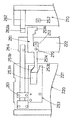
【図2】図1の金型の動作を説明する図であって、同図(a)はその射出工程時(型閉め状態)の断面図、同図(b)はその成形機取付板後退時の断面図、同図(c)はその発泡工程時の断面図である。
【図3】図1の金型の側壁用スライド型部分の分解斜視図である。
【図4】図1の金型のロック機構の動きを説明する金型の部分側面図であって、その発泡工程時の状態をあらわしている。
【図5】図1の金型のロック機構の動きを説明する金型の部分側面図であって、その型開き時状態をあらわしている。
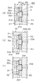
【図6】図1の金型の動作伝達機構の動きを説明する金型の部分断面図であって、射出工程時の状態をあらわしている。
【図7】図1の金型の動作伝達機構の動きを説明する金型の部分断面図であって、発泡工程時の状態をあらわしている。
【図8】図1の金型の動作伝達機構の動きを説明する金型の部分断面図であって、型開き時の状態をあらわしている。
【図9】本発明にかかる射出発泡成形用金型の第2の実施の形態に使用する金型の一つの実施の形態をあらわし、同図(a)はその射出工程時(型閉め状態)の断面図、同図(b)はその成形機取付板後退時の断面図、同図(c)はその発泡工程時の断面図である。
【図10】本発明にかかる射出発泡成形用金型の第3の実施の形態に使用する金型の一つの実施の形態をあらわし、同図(a)はその射出工程時(型閉め状態)の断面図、同図(b)はその成形機取付板後退時の断面図、同図(c)はその発泡工程時の断面図である。
【図11】本発明にかかる射出発泡成形方法の第4の実施の形態に使用する金型の一つの実施の形態をあらわし、同図(a)はその射出工程時(型閉め状態)の断面図、同図(b)はその成形機取付板後退時の断面図、同図(c)はその発泡工程時の断面図である。
【符号の説明】
100,200,300,300' 金型
120,210,320,320' 固定型
110,220,310 可動型
111,222,312 可動型本体
112 スライド型
113,221,311 成形機取付板
223 底用スライド型
224,313 側壁用スライド型
225 スライド型押さえブロック(スライド型位置規制手段)
226 油圧シリンダ(駆動手段)
250 ロック機構
251 ロック部(ロック手段)
K キャビティ[0001]
BACKGROUND OF THE INVENTION
The present invention relates to a mold for injection foam molding.
[0002]
[Prior art]
After injecting resin containing foaming agent into the mold cavity, the slide mold that forms the mold surface of the cavity in the mold is kept in the cavity space while the movable mold and fixed mold are kept closed at the parting line part. An injection foam molding method has already been proposed to produce a foam molded body in which the resin layer is foamed by sliding in the direction of expansion, the skin layer is formed along the mold surface of the mold, and the foam layer is formed inside. (See JP-A-7-88878, JP-A-8-90620, etc.).
[0003]
That is, the molded body obtained by this molding method is foamed inside, and not only has excellent heat insulation and light weight, but also has a skin layer on the surface. It has the advantage of being excellent in wear resistance.
[0004]
In the case of injection molding, a considerably large force is applied to the cavity wall surface when the resin is injected from the injection molding machine into the mold cavity. Therefore, when obtaining a large molded product, if the structure is such that there is a slide space behind the slide mold at the time of injection, each slide mold will shift due to the injection resin pressure, and after completion of injection, the slide mold will be retracted and the cavity will be retracted. Even if the resin is expanded to foam the resin, a molded product having a different foamed state may be formed for each shot. On the other hand, if a hydraulic mechanism or the like that operates each slide mold is made large in order to solve the above problem, there are problems that the mold structure is complicated, the maintainability is deteriorated, and the mold cost is increased.
[0005]
[Problems to be solved by the invention]
In view of such circumstances, the present invention provides an injection foam molding mold that has a simple mold structure, and in which a slide mold does not move due to an injection resin pressure at the time of injection and does not cause molding defects. It is intended to provide.
[0006]
[Means for Solving the Problems]
In order to achieve such an object, a foam for injection foam molding according to claim 1 of the present invention (hereinafter referred to as “mold of claim 1”) has a foaming agent-containing molten resin in a cavity. After the injection is completed, the slide mold that forms the mold surface of the cavity Slided in the cavity expanding direction by the hydraulic cylinder In an injection foam molding mold designed to foam the resin in the cavity, the slide mold is placed at a position where the cavity space is minimized. The mold closing pressure is transmitted without going through the hydraulic cylinder, and the displacement due to the injection pressure of the slide mold is prevented by the mold closing pressure, and the slide mold is moved through the hydraulic cylinder with the mold closing pressure released. Slidable in the direction that the cavity space expands The configuration.
[0007]
The injection foam molding die according to claim 2 of the present invention (hereinafter referred to as “die of claim 2”) is the mold according to claim 1, wherein the movable die is a movable die main body, and the movable die is movable. It has a split structure including a molding machine mounting plate movable in a separated state with respect to the mold body, and locks the movable mold body and the fixed mold in a closed state at least when the molding machine mounting plate moves in the mold opening direction. The lock means is provided.
[0008]
A mold for injection foam molding according to claim 3 of the present invention (hereinafter referred to as "mold of claim 3") has a plurality of slide molds in the mold of claim 1 or claim 2. These slide molds are configured to slide in conjunction with one hydraulic cylinder.
[0009]
DETAILED DESCRIPTION OF THE INVENTION
Hereinafter, the present invention will be described in detail with reference to the drawings showing embodiments thereof. However, the present invention is not limited to the illustrated embodiment, and includes design changes within a range not departing from the gist of the present invention.
1 to 7 show an embodiment of an injection foam molding die of the present invention.
[0010]
As shown in FIGS. 1 and 2, the
The
[0011]
As shown in FIG. 2, the slide
As shown in FIG. 3, the
[0012]
As shown in FIGS. 2 and 3, the
The
[0013]
That is, when the block
[0014]
The bottom slide
The
[0015]
As shown in FIGS. 1, 4, and 5, the lock opening /
The
[0016]
The locking
[0017]
The unlocking means 253 is fixed to the molding
[0018]
Next, the operation of the lock opening /
That is, as shown in FIG. 1, the lock opening /
[0019]
On the other hand, as shown in FIG. 4, even if the molding
[0020]
When the molding
[0021]
As shown in FIGS. 1 and 4 to 8, the
One end of the
[0022]
A
The
[0023]
The
[0024]
Next, the operation of the
That is, in the mold open state, as shown in FIG. 8, the
[0025]
Then, when the molding
[0026]
When the molding
[0027]
On the other hand, when the molding
[0028]
Next, an injection foam molding method using this
As shown in FIG. 2A, the fixed
[0029]
Due to the mold closing, the movement of the
The foaming agent-containing molten resin P measured by an injection molding machine (not shown) is injected into the cavity K. At this time, since the positions of the
[0030]
When the injection is completed, as shown in FIG. 2B, only the molding
[0031]
Next, as shown in FIG. 2C, in a state where the
[0032]
Then, after the resin is solidified while the
That is, at this time, since the
[0033]
As described above, since the movement of the
In addition, the molding
[0034]
Further, even when the molding
Furthermore, since the
[0035]
FIG. 9 shows a second embodiment of an injection foam molding die according to the present invention.
As shown in FIG. 9, the
[0036]
The molding
As shown in FIG. 9A, the
[0037]
The movable
The
[0038]
The
Since the other configuration is the same as that of the
[0039]
That is, in the molding method using the
When the injection is completed, as shown in FIG. 9B, only the molding
[0040]
Next, as shown in FIG. 9 (c), the
[0041]
FIG. 10 shows a third embodiment of an injection foam molding die according to the present invention.
As shown in FIG. 10, the
[0042]
That is, in the molding method using the
Then, when the injection is completed, as shown in FIG. 10B, only the molding
[0043]
Next, as shown in FIG. 10 (c), the
[0044]
FIG. 11 shows a fourth embodiment of an injection foam molding die according to the present invention.
As shown in FIG. 11, in the
[0045]
In the
As shown in FIG. 11A, the molding
[0046]
That is, in the molding method using the
[0047]
Next, while maintaining the closed state of the
[0048]
As described above, in the
In addition, since the molding
[0049]
The injection foam molding die according to the present invention is not limited to the above embodiment. For example, in the above-described embodiment, the obtained molded body has a plate shape or a rectangular box shape, but may be a cylindrical shape or a polygonal cylindrical shape.
[0050]
【The invention's effect】
As described above, since the movement of the mold for injection foam molding according to the present invention is regulated by the mold closing pressure of the movable mold, the slide mold may be displaced due to a large resin pressure at the time of injection. There is no.
That is, with a simple mold structure, the slide mold does not move due to the injection resin pressure at the time of injection, and molding defects do not occur, and a high-quality foam molded product can be manufactured stably. In addition, the mold can be reduced in size, and the cost can be reduced.
[0051]
In particular, according to the mold of claim 2, the movable mold body does not move due to the pressure during foaming, and a molded article in a good foamed state can be obtained more reliably.
[0052]
According to the mold of claim 3, all the slide molds slide at the same timing. Therefore, the foaming state of each part can always be stabilized.
[Brief description of the drawings]
FIG. 1 is a partial side view of a mold closed state showing a first embodiment of an injection foam molding die according to the present invention.
2A and 2B are diagrams for explaining the operation of the mold shown in FIG. 1, wherein FIG. 2A is a cross-sectional view during the injection process (mold closed state), and FIG. Sectional drawing at the time, (c) is a sectional view during the foaming step.
3 is an exploded perspective view of a slide mold portion for a side wall of the mold of FIG. 1. FIG.
4 is a partial side view of the mold for explaining the movement of the lock mechanism of the mold in FIG. 1, and shows a state during the foaming process. FIG.
5 is a partial side view of the mold for explaining the movement of the lock mechanism of the mold in FIG. 1, and shows a state when the mold is opened. FIG.
6 is a partial cross-sectional view of a mold for explaining the movement of the motion transmission mechanism of the mold in FIG. 1, and shows a state during an injection process. FIG.
7 is a partial cross-sectional view of the mold for explaining the movement of the motion transmission mechanism of the mold of FIG. 1, and shows a state during a foaming process. FIG.
8 is a partial cross-sectional view of a mold for explaining the movement of the motion transmission mechanism of the mold of FIG. 1, and shows a state when the mold is opened. FIG.
FIG. 9 shows one embodiment of a mold used in the second embodiment of the injection foam molding mold according to the present invention, and FIG. 9 (a) shows the injection process (mold closed state). FIG. 4B is a sectional view when the molding machine mounting plate is retracted, and FIG. 4C is a sectional view during the foaming step.
FIG. 10 shows one embodiment of a mold used in a third embodiment of an injection foam molding mold according to the present invention, and FIG. 10 (a) shows the injection process (mold closed state). FIG. 4B is a sectional view when the molding machine mounting plate is retracted, and FIG. 4C is a sectional view during the foaming step.
FIG. 11 shows one embodiment of a mold used in the fourth embodiment of the injection foam molding method according to the present invention, and FIG. 11 (a) is a cross section at the time of the injection process (mold closed state). FIG. 2B is a cross-sectional view when the molding machine mounting plate is retracted, and FIG. 1C is a cross-sectional view during the foaming process.
[Explanation of symbols]
100, 200, 300, 300 'mold
120, 210, 320, 320 ′ fixed type
110, 220, 310 Movable type
111, 222, 312 Movable body
112 Slide type
113, 221, 311 Molding machine mounting plate
223 Slide type for bottom
224,313 Side wall slide type
225 Slide-type holding block (slide-type position restricting means)
226 Hydraulic cylinder (drive means)
250 Lock mechanism
251 Locking part (locking means)
K cavity
Claims (3)
Priority Applications (1)
| Application Number | Priority Date | Filing Date | Title |
|---|---|---|---|
| JP2001344802A JP3728237B2 (en) | 2001-11-09 | 2001-11-09 | Injection foam mold |
Applications Claiming Priority (1)
| Application Number | Priority Date | Filing Date | Title |
|---|---|---|---|
| JP2001344802A JP3728237B2 (en) | 2001-11-09 | 2001-11-09 | Injection foam mold |
Publications (2)
| Publication Number | Publication Date |
|---|---|
| JP2003145582A JP2003145582A (en) | 2003-05-20 |
| JP3728237B2 true JP3728237B2 (en) | 2005-12-21 |
Family
ID=19158265
Family Applications (1)
| Application Number | Title | Priority Date | Filing Date |
|---|---|---|---|
| JP2001344802A Expired - Fee Related JP3728237B2 (en) | 2001-11-09 | 2001-11-09 | Injection foam mold |
Country Status (1)
| Country | Link |
|---|---|
| JP (1) | JP3728237B2 (en) |
Families Citing this family (2)
| Publication number | Priority date | Publication date | Assignee | Title |
|---|---|---|---|---|
| KR100973762B1 (en) * | 2006-01-17 | 2010-08-04 | 도요타 지도샤(주) | Mold for molding and method for molding product |
| CN108312417B (en) * | 2018-03-19 | 2024-01-19 | 江苏昊晟塑业科技有限公司 | Foaming temperature control device of foam molding machine |
-
2001
- 2001-11-09 JP JP2001344802A patent/JP3728237B2/en not_active Expired - Fee Related
Also Published As
| Publication number | Publication date |
|---|---|
| JP2003145582A (en) | 2003-05-20 |
Similar Documents
| Publication | Publication Date | Title |
|---|---|---|
| JP5749065B2 (en) | Injection molding machine and injection molding method | |
| JP2927687B2 (en) | Molding method and molding device | |
| JP3728237B2 (en) | Injection foam mold | |
| JP3943696B2 (en) | Manufacturing method of laminated molded product | |
| JP7007690B2 (en) | Slide mechanism, movable mold and molding mold | |
| KR102085969B1 (en) | apparatus and method of forming foaming mold | |
| JP2008094052A (en) | Multilayer injection molding method of resin, and multilayer injection molding apparatus of resin | |
| JPH08197578A (en) | Method and apparatus for molding composite molded product | |
| JP2009029084A (en) | Drive for valve pin in injection molding die | |
| JP5349027B2 (en) | Two-layer foam molding method and apparatus | |
| JP4106320B2 (en) | Injection molding method | |
| KR102029950B1 (en) | apparatus and method of forming foaming mold | |
| JP2010143094A (en) | Method for manufacturing skin-integrated foam molded article and foam molding mold used for the same | |
| JP4199585B2 (en) | Mold clamping device and core back method for injection molding machine, etc. | |
| JP4204724B2 (en) | Vehicle sun visor | |
| JP2007030441A (en) | Manufacturing method of resin molding | |
| JP2001310335A (en) | Molding equipment for foam synthetic resin molding | |
| JP2005288745A (en) | Method for producing injection-molded article | |
| KR102019175B1 (en) | micro opening control mold and method of forming the same | |
| JP2671602B2 (en) | Molded product discharge device of resin molding machine | |
| JP2657193B2 (en) | Injection mold equipment | |
| JP2008179002A (en) | Molding apparatus and molding method | |
| JP2732676B2 (en) | Injection molding equipment | |
| WO1998021018A1 (en) | Compression device for molding, injection compression molding machine, and injection compression molding method using compression device | |
| JP2004299158A (en) | Mold assembly for injection molding |
Legal Events
| Date | Code | Title | Description |
|---|---|---|---|
| A977 | Report on retrieval |
Free format text: JAPANESE INTERMEDIATE CODE: A971007 Effective date: 20040601 |
|
| A131 | Notification of reasons for refusal |
Free format text: JAPANESE INTERMEDIATE CODE: A131 Effective date: 20040608 |
|
| A521 | Written amendment |
Free format text: JAPANESE INTERMEDIATE CODE: A523 Effective date: 20040805 |
|
| TRDD | Decision of grant or rejection written | ||
| A01 | Written decision to grant a patent or to grant a registration (utility model) |
Free format text: JAPANESE INTERMEDIATE CODE: A01 Effective date: 20050830 |
|
| A61 | First payment of annual fees (during grant procedure) |
Free format text: JAPANESE INTERMEDIATE CODE: A61 Effective date: 20050930 |
|
| R150 | Certificate of patent or registration of utility model |
Free format text: JAPANESE INTERMEDIATE CODE: R150 |
|
| FPAY | Renewal fee payment (event date is renewal date of database) |
Free format text: PAYMENT UNTIL: 20091007 Year of fee payment: 4 |
|
| FPAY | Renewal fee payment (event date is renewal date of database) |
Free format text: PAYMENT UNTIL: 20091007 Year of fee payment: 4 |
|
| FPAY | Renewal fee payment (event date is renewal date of database) |
Free format text: PAYMENT UNTIL: 20101007 Year of fee payment: 5 |
|
| FPAY | Renewal fee payment (event date is renewal date of database) |
Free format text: PAYMENT UNTIL: 20111007 Year of fee payment: 6 |
|
| FPAY | Renewal fee payment (event date is renewal date of database) |
Free format text: PAYMENT UNTIL: 20111007 Year of fee payment: 6 |
|
| FPAY | Renewal fee payment (event date is renewal date of database) |
Free format text: PAYMENT UNTIL: 20121007 Year of fee payment: 7 |
|
| FPAY | Renewal fee payment (event date is renewal date of database) |
Free format text: PAYMENT UNTIL: 20121007 Year of fee payment: 7 |
|
| FPAY | Renewal fee payment (event date is renewal date of database) |
Free format text: PAYMENT UNTIL: 20131007 Year of fee payment: 8 |
|
| R250 | Receipt of annual fees |
Free format text: JAPANESE INTERMEDIATE CODE: R250 |
|
| LAPS | Cancellation because of no payment of annual fees |