JP3726533B2 - Lithium secondary battery, its electrolyte and electrical equipment - Google Patents
Lithium secondary battery, its electrolyte and electrical equipment Download PDFInfo
- Publication number
- JP3726533B2 JP3726533B2 JP03681899A JP3681899A JP3726533B2 JP 3726533 B2 JP3726533 B2 JP 3726533B2 JP 03681899 A JP03681899 A JP 03681899A JP 3681899 A JP3681899 A JP 3681899A JP 3726533 B2 JP3726533 B2 JP 3726533B2
- Authority
- JP
- Japan
- Prior art keywords
- solvent
- carbonate
- battery
- electrolyte
- volume
- Prior art date
- Legal status (The legal status is an assumption and is not a legal conclusion. Google has not performed a legal analysis and makes no representation as to the accuracy of the status listed.)
- Expired - Fee Related
Links
Images


Classifications
-
- Y—GENERAL TAGGING OF NEW TECHNOLOGICAL DEVELOPMENTS; GENERAL TAGGING OF CROSS-SECTIONAL TECHNOLOGIES SPANNING OVER SEVERAL SECTIONS OF THE IPC; TECHNICAL SUBJECTS COVERED BY FORMER USPC CROSS-REFERENCE ART COLLECTIONS [XRACs] AND DIGESTS
- Y02—TECHNOLOGIES OR APPLICATIONS FOR MITIGATION OR ADAPTATION AGAINST CLIMATE CHANGE
- Y02E—REDUCTION OF GREENHOUSE GAS [GHG] EMISSIONS, RELATED TO ENERGY GENERATION, TRANSMISSION OR DISTRIBUTION
- Y02E60/00—Enabling technologies; Technologies with a potential or indirect contribution to GHG emissions mitigation
- Y02E60/10—Energy storage using batteries
Description
【0001】
【発明の属する技術分野】
本発明はリチウムイオンを可動イオンとする非水電解液とそれを用いたリチウム2次電池とその電解液及び電気機器に関する。
【0002】
【従来の技術】
非水電解液を用いたリチウム2次電池は、高電圧・高エネルギー密度を有し、且つ、貯蔵性能や低温動作性に優れ、広く携帯用民生電気製品に利用されている。また、この電池を大型化し、電気自動車用や家庭用の夜間電力貯蔵装置として活用していくための研究・開発が盛んに行われている。
【0003】
しかし、これらに利用される溶媒の多くは引火点が低く、燃焼性が高いため、過充電や加熱等により発火,爆発等の危険性がある。そこで、最近ではこの電池の安全性を確保するための提案が増加してきている。例えば、特開平7−192762 号公報では燃焼抑制効果が期待できるハロゲン化ギ酸エステルを環状炭酸エステルに混合することにより、燃焼性を低減することが開示されている。また、特開平8−45544号公報にはハロゲン化されたエステルを混合することが開示されているが、ハロゲン化ギ酸エステルやハロゲン化エステル類は、ハロゲン化していない環状カーボネートよりも引火点が低い場合もあり、十分な難燃化が実現されたとは考え難い。この他の手段として、特開平4−184370 号公報や特開平8−88023号公報では、自己消火作用が期待されるリン酸エステルを電解液に含有することが記されているが、サイクル特性が若干劣る傾向がある。
【0004】
以上は自己消火性が高い溶媒や、消火作用のある溶媒を非水電解液に用いる例であるが、それ自体が不燃性であるフッ素化合物を非水電解液溶媒とすることはリチウム2次電池を不燃化する究極の手段である。フッ素化合物の利用に関しては、特開平9−293533 号公報ではフッ素化アルカンを溶媒に0.5〜30 重量%までの範囲で混合して難燃化することが開示されている。この例におけるフッ素化アルカンの作用は、これら低沸点のフッ素化合物による混合気体の窒息による消火作用であり、混合する割合から考えても不燃性溶媒を用いた電解液とは言い難い。また、特開平9−293533 号公報には、25℃以下の沸点を有するフッ素化合物を電池内に内在させ、電池が高温に曝されたりした場合にフッ素化合物が可燃性溶媒よりも先に気化し、その蒸気で可燃性溶媒の燃焼を窒息させることによって難燃化しようとする方法が開示されている。この例は、不燃性溶媒を電解液とは分離した形態で用いたものであり、不燃性溶媒を電解液として利用しようとするものではない。
【0005】
【発明が解決しようとする課題】
前述の如く、リチウム2次電池の安全性を確立するために電解液の不燃化が重要である。しかしながら、不燃性液体の代表的存在である不燃性溶媒の特性は、一般に双極子モーメントが小さく、誘電率が低いためにリチウム塩の溶解性が非常に乏しい。また、リチウム塩の解離性の良好な双極子モーメントの大きな非水溶媒との相溶性も低く、これらと不燃性溶媒とは混合できず、2層に分離してしまう。この様に、不燃性溶媒は、電解液に要求される物性を全く示さないものである。しかし、リチウム2次電池の唯一の欠点である電解液の燃焼性の問題を解決することが、この電池を大型化し電気自動車や家庭用途へと普及させるために不可欠である。
【0006】
本発明の目的は、高温,加熱,過充電,内部短絡等による爆発,発火,発煙等の危険性を解消したリチウム2次電池とその電解液及び電気機器を提供するにある。
【0007】
【課題を解決するための手段】
本発明は、導電率が0.05ms/cm以上、好ましくは0.1〜3ms/cm、より好ましくは0.2〜2.5ms/cmであり、JIS−K2265試験で引火点を有しない非水電解液を有することを特徴とするリチウム2次電池にある。
【0008】
本発明は、リチウムを吸蔵・放出可能な負極と、リチウムを吸蔵・放出可能な正極と、セパレーター及びリチウム塩を含む非水電解液を有するリチウム2次電池において、前記非水電解液が、非イオン導電性溶媒、好ましくはきわめて難燃性を有する不燃性である溶媒と、リチウムイオン導電性溶媒との混合溶液を含み、前記電解液はJIS−K2265試験で引火点を有しないことを特徴とする。本発明における非イオン導電性溶媒とイオン導電性溶媒との割合は後者の量を10〜40容量%とすることにより前述の引火点を有しないものが得られる。
【0009】
本発明は、リチウム2次電池において、非水電解液が20容量%以上が非イオン導電性溶媒とリチウムイオン導電性溶媒とを含むことを特徴とする。
【0010】
本発明は、非水電解液が、非イオン導電性溶媒と、リチウムイオン導電性溶媒との混合溶液を含み、前記電解液の導電率が0.1〜3ms/cm であることを特徴とするリチウム2次電池にある。
【0011】
本発明は、非水電解液が、非イオン導電性溶媒と、リチウムイオン導電性溶媒との混合溶液を含み、前記リチウムイオン導電性溶媒の双極子モーメントが3デバイ以下であることを特徴とするリチウム2次電池にある。
【0012】
本発明は、非水電解液が、非イオン導電性溶媒と、リチウムイオン導電性溶媒との混合溶液を含み、前記リチウムイオン導電性溶媒は双極子モーメントが3デバイ未満のものと3デバイ以上のものを含むことを特徴とするリチウム2次電池にある。
【0013】
本発明は、非水電解液が、非イオン導電性溶媒及びリチウムイオン導電性溶媒を含み、前記リチウム塩は有機リチウム塩と無機リチウム塩とを有することを特徴とするリチウム2次電池にある。
【0014】
本発明は、非イオン導電性溶媒及びリチウムイオン導電性溶媒を含み、導電率が0.1ms/cm 以上であり、JIS−K2265試験で引火点を有しないものであることを特徴とするリチウム2次電池用非水電解液にある。
【0015】
ここで、本発明に係る非イオン導電性溶媒は不燃性溶媒と略して以後説明する。不燃性溶媒はリチウム塩を溶解しないが、不燃性溶媒の物性に応じたある限界値までは低双極子モーメントの非水溶媒で構成されるリチウム塩を溶解・解離したイオン導電性のある溶液を相溶または分散させる形で混合させることができ、この混合液は電解液として機能するものであることを見出した。
【0016】
また本発明に係る電解液についても不燃性電解液と称して以後説明する。
【0017】
本発明の不燃性電解液は、フッ素化性溶媒中に、リチウム塩を溶解・解離した双極子モーメントの値が3デバイ以下の非水溶媒が相溶または分散した状態の溶液である。これを電解液として用いることによりきわめて高い安全性を有するリチウム2次電池が得られるものであるフッ素化溶媒の一具体例としては、化1
【0018】
【化3】

(式中、mは2〜8の整数を表わし、nは1〜5の整数を表わし、mとnの関係は、m≧((6n+1)/4)である。)で表わされるフッ素化エーテルを用いることができる。これらの溶媒は、分子軌道計算から得られる双極子モーメントの値が2デバイ程度であり、相溶性を高める観点から混合する非水溶媒の双極子モーメントの値も2デバイに近いか又はこれ以下のものが望ましく、非水溶媒の双極子モーメントは大きくとも3デバイまでが好適である。
【0020】
本発明の不燃性電解液の中のフッ素化溶媒を以後不燃性フッ素化溶媒と称して説明する。不燃性フッ素化溶媒には、例えば、パーフロロブチルメチルエーテル,パーフロロブチルエチルエーテル,パーフロロペンチルメチルエーテル,パーフロロペンチルエチルエーテル,パーフロロヘプチルメチルエーテル,パーフロロヘプチルエチルエーテル等から選ばれる1つ乃至は複数の溶媒が用いられる。特に、前記2者のものが好ましい。また、イオン導電性溶媒である非水溶媒としては、例えば、ジメチルカーボネート,エチルメチルカーボネート,ジエチルカーボネート,メチルプロピルカーボネート,エチルプロピルカーボネート,ジプロピルカーボネート,ビス(トリフロロエチル)カーボネート,ビス(ペンタフロロプロピル)カーボネート,トリフロロエチルメチルカーボネート,ペンタフロロエチルメチルカーボネート,ヘプタフロロプロピルメチルカーボネート,パーフロロブチルメチルカーボネート,トリフロロエチルエチルカーボネート,ペンタフロロエチルエチルカーボネート,ヘプタフロロプロピルエチルカーボネート,パーフロロブチルエチルカーボネート等または化2
【0021】
【化4】
(式中、pは2〜10の整数、R1は水素または炭素数1〜3のアルキル基、R2は炭素数1〜3のアルキル基)で表わされるフッ素化オリゴマーの中から選ばれる1乃至複数の非水溶媒が用いられ、双極子モーメントの値が3デバイ以下が好ましい。フッ素化溶媒とイオン導電性非水溶媒とは相溶状態を形成する。
【0023】
有機リチウム塩としては、例えば、LiCF3SO2,LiN(CF3SO2)2,LiN(CF3SO2)(CF3CF2CF2CF2SO2),LiN(CF3CF2SO2)2,LiC(CF3SO2)2,LiC(CF3CF2SO2)2,Li〔PF4(CF(CF3)2)〕の1つ又は複数を用いることができる。
【0024】
無機リチウム塩としては、LiPF6,LiBF4,LiF,LiBr,LiI,LiCl,LiBr,LiClO4 等の中から選ばれる1乃至複数のものが用いられる。先の不燃性溶媒と非水溶媒の混合溶媒にこれらのリチウム塩を溶解するとリチウム塩は非水溶媒によって溶解・解離されて、溶媒和した非水溶媒によってリチウムイオンとカウンターアニオンは取り囲まれ、フッ素化溶媒中に相溶した状態が実現する。更に、混合するリチウム塩の濃度が増加すると、非水溶媒がリチウムイオンやカウンターアニオンと十分な溶媒和圏を形成できなくなり、リチウムイオンまたはカウンターアニオンと接する不燃性溶媒ができてしまい溶媒系のエネルギーが不安定化するので、幾つかの溶媒和が寄り集まりより大きな溶媒和圏を形成し、不燃性溶媒分子が直接イオンに接しない状態を形成する。マクロ的にはイオンを含む非水溶媒分子がフッ素溶媒中でミセル模様のものを形成し、導電性溶液が非導電性溶媒(不燃性溶媒)中に分散した状態を形成する。
【0025】
以上の様な相溶状態または分散状態で不燃性溶媒分子とリチウム塩を溶解・解離した非水溶媒分子が混合された溶液が不燃性電解液として利用し得る。しかし、リチウム塩の濃度が不燃性溶媒分子と非水溶媒分子の相溶性や、非水溶媒とリチウム塩の溶解性等で決まるある限界値を超えると、混合溶液は不燃性溶媒分子からリチウム塩を溶解した非水溶媒溶液が分離してしまい電解液でなくなってしまう。不燃性溶媒としては、フッ素化溶媒であるパーフロロブチルメチルエーテルまたはパーフロロブチルエチルエーテルが好ましい。
【0026】
負極には難黒鉛性炭素,天然又は人造の黒鉛炭素、或いは、錫酸化物,珪素またはゲルマニウム化合物、或いは、リチウム金属またはリチウム合金等が負極活物質として挙げられる。また、正極にはコバルト,ニッケル,マンガン等遷移金属のリチウム複合酸化物、或いは、これらリチウム複合酸化物のリチウムサイトまたは遷移金属サイトの一部をコバルト,ニッケル,マンガン,アルミニウム,ホウ素,マグネシウム,鉄,銅等で置換された化合物、或いは、フェロシアンブルー,ベルリングリーン等の鉄錯体化合物等が好適な正極材料として挙げられる。
【0027】
セパレーターには微多孔性の高分子フィルムを用いる。例えば、ナイロン,セルロース,ニトロセルロース,ポリスルホン,ポリアクリロニトリル,ポリフッ化ビニリデン,ポリプロピレン,ポリエチレン,ポリブテン等が挙げられる。
【0028】
電池形状は特定の形に限定されるものではない。例えば、円筒型,コイン型,角形電池等の形状の電池とすることができる。また、電池容量に関しても特別の制限はなく、民生用の数Whのものから家庭用電力貯蔵用や電気自動車用の数百Whのものまで適応可能である。
【0029】
本発明は、電解液を引火点を有しないものとし、その負荷特性の向上を目的にリチウム塩を含む非水電解液組成を鋭意検討した結果、以下の電解液を用いたものである。
【0030】
(a)フッ素化溶媒を40〜95容量%、
(b)半経験的分子軌道計算から得られる双極子モーメントが3デバイ未満の低双極子モーメント溶媒を5〜60容量%、及び、
(c)半経験的分子軌道計算から得られる双極子モーメントが3デバイ以上の高双極子モーメント溶媒を0.1〜10容量%を含み、
(d)有機リチウム塩を0.2〜1.2モル/リッター及び
(e)無機リチウム塩を0.005〜0.5モル/リッターの(d)及び(e)の一方又は両方を有し、特に電解液としてJIS2265の引火点試験において引火点のない組成とするものである。フッ素化溶媒としては(化5)に示すnが4〜12で表わされるメチルパーフロロアルキルエーテルを用いることができる。
【0031】
【化5】
また、3デバイ未満の鎖状の低双極子モーメント溶媒には、ジメチルカーボネート(DMC),エチルメチルカーボネート(EMC),ジエチルカーボネート(DEC),メチルプロピルカーボネート(MPC),メチルトリフロロエチルカーボネート(MTFEC),ジメトキシエタン(DME),トリグライム (TGM)の中から選ばれる溶媒を1つまたは混合して用いることができる。3デバイ以上の高双極子モーメント溶媒としては、エチレンカーボネート(EC),プロピレンカーボネート(PC),トリフロロプロピレンカーボネート(TFPC),クロロエチレンカーボネート(ClEC),ビニレンカーボネート(VC),ブチレンカーボネート(BC),ジメチルビニレンカーボネート(DMVC),γ−ブチロラクトン(GBL)の中から選ばれる溶媒を1つまたは複数混合して用いることができる。有機リチウム塩としては、前述のものが用いられる。無機リチウム塩には、前述のものが用いられる。
【0033】
本発明は、フッ素化溶媒としてメチルパーフロロブチルエーテルを65容量%以上含み、低双極子モーメントの溶媒としてジメチルカーボネート,エチルメチルカーボネート,ジエチルカーボネート,ジメトキシエタン,トリグライムの1つまたは複数を25容量%未満で含み、高双極子モーメントの溶媒として前述の化合物の1つまたは複数を0.1 〜10容量パーセントの範囲で含み、有機リチウム塩としてLiN(SO2CF2CF3)2を0.2〜1.2モル/リッターの濃度で含み、無機リチウム塩としてLiPF6 を0.005〜0.5モル/リッターの範囲で含み、好ましくは、JIS2265の引火点試験において引火点のない組成の不燃性電解液を用いたリチウム2次電池にある。
【0034】
電解液に用いるフッ素化溶媒の満たすべき要件は、引火点のない不燃性溶媒であること、低双極子モーメントの溶媒または高双極子モーメントの溶媒との相溶性があることである。本発明において、フッ素化溶媒には一般の電解液溶媒に求められるリチウム塩の溶解性は特に必要としない。従って、多くの鎖状フッ素化溶媒を不燃性溶媒として用いることが可能であり、パーフロロアルカン,セミフロロアルカンまたはこれらに塩素や臭素を導入した誘導体等も利用できる。しかし、環境影響性や毒性を考えると良好な材料とは言い難い。フロン洗浄剤の環境対応の代替洗浄剤として導入されたハイドロフロロエーテルは、これらの問題がなく、且つ、電解液溶媒に比べて高価なこともなく、不燃性電解液の不燃化溶媒として好適である。即ち、フッ素化溶媒としては前述の式(5)(式中、nは4〜12の整数を表わす。)で表わされるメチルパーフロロアルキルエーテルを用いるのが好適である。これらの溶媒としては、メチルパーフロロブチルエーテル,メチルパーフロロペンチルエーテル,メチルパーフロロヘキシルエーテル,メチルパーフロロヘプチルエーテル,メチルパーフロロオクチルエーテル,メチルパーフロロノニルエーテル,メチルパーフロロデシルエーテル,メチルパーフロロウンデシルエーテル,メチルパーフロロドデシルエーテルを挙げることができる。
【0035】
一般にフッ素化した溶媒は双極子モーメントが小さいので、それらに混合する第一の溶媒としては鎖状の低双極子モーメントの溶媒の方が相溶性が良い。この様な溶媒としては、前述の通りである。
【0036】
これらハイドロフロロエーテルと低双極子モーメントの溶媒との混合溶媒は、有機リチウム塩を、混合溶媒の種類と混合割合にも依存するが、フッ素化溶媒が80容量%以上の領域においても、1.2M 程度まで溶解することができる。これら可溶な有機リチウム塩としては、前述の通りである。これらのうち、 LiN(SO2CF2CF3)2,LiC(SO2CF2CF3)3,LiC(SO2CF3)3,Li〔PF4(CF(CF3)2)〕 が正極集電体にアルミを用いる現状の電池では、高電位においてアルミとの反応性が小さく好適である。
【0037】
以上の構成材料を用いることによって不燃性電解液を実現できるが、更に負荷特性を向上するためには、充放電時の活物質界面でのリチウムイオンの挿脱入抵抗を低減するための皮膜が必要である。SEI(Surface Electrode Interface)と称されている(例えば、J. Electrochemical Soc.,p.2882,vol.142 (1995)等)溶媒の電極近傍での反応生成物は、電解液中に存在する反応性の高い化合物の種類及びそれらの化合物が反応する場となる混合された溶媒の種類及び混合の割合等によりその性質が左右される。上記の構成材料の電解液では、負荷特性を維持するのに十分なSEIが得られていないと考えられる。そこで、SEIのプレカーサーとしてリチウムイオンとの配位性の高い、高双極性モーメントを有する溶媒を混合した。高双極子モーメントの溶媒の添加量が多くなると、電解液が相分離を起こし使用できなくなるので、0.1 〜10容量パーセントの範囲での添加が好適である。更に、この組成に、単独ではフッ素化溶媒やフッ素化溶媒混合物への溶解性の極めて低い無機リチウム塩を添加することにより、負荷特性は更に安定したものになる。添加する無機リチウム塩としては、前述の化合物を用いることができるが、特に、正極にアルミ集電体を使用する場合にはアルミ表面に電気化学的に安定な皮膜を形成できるフッ素を有する化合物 LiPF6,LiBF4およびLiFが好適である。これら無機リチウム塩は溶解度が高くないので、0.005〜0.5モル/リッターの範囲での添加が好適である。
【0038】
本発明は、リチウム2次電池を電源に用いた電気機器において、前記2次電池の過充電及び過放電に対する保護手段は前記電池の温度及び圧力検出がフリーであり、前記電池の電圧又は電流検出手段及び該検出値に基づいて前記電源を開閉する制御手段を有することを特徴とする。
【0039】
【発明の実施の形態】
[実施例1〜9,比較例1]
不燃性フッ素溶媒として住友スリーエム(株)製ノナフロロブチルメチルエーテル(商標:HFE7100),半経験的分子軌道計算(MOPAC)から求めた双極子モーメントは2.37 デバイである。非水溶媒としてエチルメチルカーボネート(EMC)を用い、同様にして得た双極子モーメントは0.887 デバイである。また、リチウム塩にはビストリフロロメチルスルホニルイミド(LiTFMSI)を用いた。
【0040】
【表1】
表1に示す溶媒混合割合の実施例1〜9の電解液と比較例1の電解液のリチウム塩濃度と溶解・混合性、及び、各濃度における導電率を評価した。
【0042】
図1はリチウム塩濃度と導電率変化との関係を示す線図である。図示した様に、導電率はEMCの混合割合の増加と共に向上する事が分かった。また、EMCの混合割合が50容量%以上ではリチウム塩濃度が1M(モル/リッター)を超えても導電率の低下が見られず、更に多くのLiTFSIを溶解できることが分かった。尚、これらの実施例及び比較例では、評価したリチウム塩濃度領域において、非水電解液のフッ素溶媒中での分散やフッ素溶媒からの分離は認められなかった。即ち、HFE7100とEMCから成る電解液はほぼすべての混合比で相溶状態の電解液を調製でき、不燃性が高く好ましい混合領域であるHFE7100 が40容量%以上の混合割合でも、十分な導電率(0.95Mのリチウム塩濃度において、EMC単独非水溶媒を用いた比較例1の電解液の約3分の1の導電率)を有していることが分かった。
【0043】
[実施例10〜14,比較例2〜5]
不燃性フッ素化溶媒HFE7100の混合割合を80容量%,非水溶媒の混合割合を20容量%と一定として、非水溶媒の種類を変えた結果を表2に示す。
【0044】
【表2】
表2に示す様に実施例10〜14と比較例2〜5の溶媒間の相溶性,電解液の混合状態と導電率を評価した。ここで、DMCはジメチルカーボネート、DECはジエチルカーボネート、TFEMCはトリフロロエチルメチルカーボネート、BTFPCはビストリフロロプロピルカーボネート、DOLは1,3−ジオキソラン、PCはプロピレンカーボネート、ECはエチレンカーボネート、GBLはγ−ブチロラクトン、BCはブチレンカーボネートを表わす。
【0046】
この表から分かる様に、双極子モーメントが3デバイよりも大きな比較例2〜5の溶媒、即ちPC,EC,GBL,BCは不燃性溶媒HFE7100と相溶しない。このことから、溶媒の極性の差が相溶性に大きく作用していると考えられる。更に、双極子モーメントが3デバイよりも小さな溶媒であってもDOL (1.256デバイ)の様な環状の分子は、不燃性溶媒との混合状態が分散となる。また、鎖状の溶媒であってもBTFPC(2.719 デバイ)の様に双極子モーメントが大きくなるとリチウム塩の溶解性が低下してくる。以上のことから、フッ素系不燃性溶媒に対する混合溶媒には、双極子モーメントが3デバイ以下のものが好適である。
【0047】
[実施例15〜18]
図2は、HFE7100 80容量%とEMC 20容量%の混合溶媒に対する各種リチウム塩の溶解性に関係する濃度依存性とそれら電解液の導電率との関係を示す線図である。リチウム塩として、実施例15は住友スリーエム(株)製のビスペンタフロロエチルスルホニルイオミド(LiBETI)、実施例16はセントラルガラス社製のパーフロロブチルメチルスルホニルイミド(LiFBMSI)、実施例17はヘキサフロロリン酸リチウム(LiPF6 )、実施例18はテトラフロロホウ酸リチウム(LiBF4 )を用いたものである。尚、図中で途中でプロットがなくなっているものは、不燃性溶媒と非水溶媒電解液が分離し測定できなくなったものである。
【0048】
図示した様に、この混合溶媒系ではLiPF6やLiBF4等の無機塩よりもフッ素鎖を有するLiTFSI,LiBETI,LiFBMSI等の有機塩の方が溶解・解離性が高く、導電率も良好な値になることが分かった。これは、これら無機塩はその解離アニオンが対象性が高く、双極子モーメントが殆んどゼロ(計算値では、PF6 -は0.001、BF4 -は0.001デバイである)であり、また、分子半径が小さいため帯電性が高く、誘電率の低い不燃性フッ素溶媒との親和性が低下するためと考えられる。
【0049】
これに対して、有機塩の解離アニオンは双極子モーメントを有し(計算値では、TFSI- は1.23 、BETI- は1.103 、FBMSI- は8.468 デバイである)、分子半径も大きく、且つ、ここに示した有機アニオンはフッ素鎖を持っているので不燃性フッ素溶媒との親和性が良いことが溶解性の高さに寄与しているものと考えられる。即ち、有機リチウム塩の方が不燃性電解液の電解質として好適な材料である。なかでもフッ素鎖長の短いLiTFSIはカウンターアニオンの拡散性が良く、不燃性電解液用の電解質として優れている。
【0050】
[実施例19〜23,比較例6]
【0051】
【表3】
表3は種々の組成の不燃性電解液を用いた実施例19〜23の電池と従来の電解液を用いた比較例7の電池を作製し、電池特性と安全性を評価した結果を示すものである。尚、HFE7200は3M社製の不燃性溶媒,ノナフロロブチルエチルエーテルを表わす。
【0053】
図3は本実施例における外形直径18mm,高さ65mmの円筒型電池の断面図である負極活物質9には人造黒鉛,正極活物質10にはコバルト酸リチウム、セパレーター11には25ミクロンのポリエチレン微多孔質フィルムを用いたものである。電池は、電解液をグローブボックス中で真空含浸によって注液後、圧力限界が5気圧の内圧開放弁12を2個設けた電池正極蓋13を取り付け、電池缶
14とこの蓋をレーザー溶接15して密閉して作製した。
【0054】
正極10は正極活物質としてLiCoO2 、導電剤としてアセチレンブラックを7wt%,結着剤としてポリフッ化ビニリデン(PVDF)を5wt%添加して、これにN−メチル−2−ピロリドンを加え混合して正極合剤のスラリーを調製した。
【0055】
同様に負極活物質として菱面体晶が1〜20重量%、残部が六方晶である平均粒径8μmの黒鉛粉末、結着剤としてPVDFを10wt%添加して、これにN−メチル−2−ピロリドンを加え混合して負極合剤のスラリーを調整した。
【0056】
正極合剤を厚み20μmのアルミニウム箔の両面に塗布し、その後120℃で1時間真空乾燥した。真空乾燥後、ローラープレスによって電極を加圧成型して厚みを195μmとした。単位面積当りの合剤塗布量は55mg/cm2 であった。黒鉛粉末の菱面体晶の割合は900℃以上の温度で加熱処理することにより調整することができ、少ない方が好ましい。
【0057】
一方、負極合剤は厚み10μmの銅箔の両面に塗布し、その後120℃で1時間真空乾燥した。真空乾燥後、ローラープレスによって電極を加圧成型して厚みを175μmとした。単位面積当りの合剤塗布量は25mg/cm2 であった。
【0058】
前述によって得られた正極10,セパレーター11,負極9及びセパレーター11の順に積層したものを巻回して電池缶14に収納したものである。16は絶縁板、17は負極リード、18は正極リードである。
【0059】
電池缶14及び電池正極蓋13には、JIS規格のSUS304又は316のオーステナイト系ステンレス鋼を用いた。
【0060】
比較例6の初回容量が1300mAhであったので、この容量を基準に0.5C(650mA)で各電池の充放電サイクル試験を300サイクルまで実施した。また、安全性試験としては満充電した状態の電池を横置きしてその中央部をガスバーナーの直火で加熱する安全試験1、及び、電池中央部に直径5mmの釘を電池直径の半分まで差し込む安全試験2を実施した。表3に示す様に、本発明の不燃性電解液を用いた電池、実施例19〜23は、電池特性的には初回容量1200mAh以上,容量維持率90%以上の従来電解液を用いた比較例6の電池とまったく遜色なく、そして発火の生じない安全性が極めて向上していることが実証された。
【0061】
[実施例24〜28,比較例7]
【0062】
【表4】
表4は種々の組成の不燃性電解液を用いた実施例24〜28の電池及び比較例7の電解液を用い、正極にマンガン酸リチウム、負極に非晶質黒鉛、セパレーターに40ミクロンのポリエチレンフイルムを用い、図4に示す構造の直径80mm,高さ240mmの円筒型の実施例24〜28及び比較例7の大容量電池を作製し、上記と同様の電池特性と安全性を評価した結果を示すものである。尚、この電池も負極9,正極10,電池缶14及び電池正極蓋13には前述の実施例と同様の材料を用いた。電池正極蓋13には耐圧5気圧の内圧開放弁12を設け、電池缶14と電池正極蓋とはレーザで溶接(レーザ溶接部15)して作製した。
【0064】
電池の初回容量は本発明に係る実施例24〜28では26〜27Ahであり、比較例7では、27Ahであった。電池特性は電流値10Aで300サイクルの充放電試験を実施した結果、容量維持率は97%以上であった。尚、この大型電池では約100mlの電解液を内包しているが、安全試験2では電池内部の短絡により一時的に電池温度が急上昇し、従来電解液では発煙が起こるのに対して不燃性電解液ではその主成分であるフッ素系溶媒(毒性は殆どなく、地球温暖化係数も低い)が蒸発して逸散したと考えられるが、濃厚な発煙は見られなかった。即ち、本発明の不燃性電解液を用いることにより、大容量の電池でも従来の電解液を用いた電池と同等の電池特性が得られ、大型電池では特に重要となる安全性が飛躍的に向上できた。
【0065】
以上に記載の通り、導電率が低くても電池容量,負荷特性ともに従来の非水電解液と比較して特性低下は見られなかった。これは、即ち、フッ素系の不燃性溶媒が混合しているイオン導電性の非水溶媒の形成するイオン伝導経路を阻害していないことを示唆するものである。換言すれば、従来の非水電解液もセパレーターの狭い空孔を通してイオンが伝導していたわけで、不燃性溶媒もこれと同様な作用体、いわば液体のセパレーターのような存在になっているにすぎないのではないかと考えることができる。更に推定するに、イオン伝導経路におけるイオン濃度は従来の非水電解液に比べ高くなっており、従来の系に比べ非常に高率の電解液系が実現されていると考えることもできる。
【0066】
[実施例29]
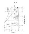
図5は前述の実施例で示した各種イオン導電性溶媒の含有量とJIS−K2265試験による引火点の関係を示す線図である。不燃性溶媒はHFE7100である。図に示す如く、溶媒の種類によって引火点なしの含有量が変わる。b.p.は弗点である。EMC,DMCは30容量%未満、DMEは20容量%未満とするのが好ましい。TGM及びDECは30容量%以下で好ましい。
【0067】
[実施例30]
図6は本発明の非水電解液を用いた直径18mm,高さ65mmの円筒型電池の部分断面図である。負極活物質とした黒鉛炭素材料90重量部を、結着剤であるポリフッ化ビニリデンフロライド(PVDF)10重量部と共にNーメチルピロリドンに溶解・混練して負極材料のペーストを調製した。この負極材料ペーストを厚さ10μmの銅箔集電体1の両面に塗布し、加熱乾燥したのち、加圧・加熱処理して負極2を作製した。次に、この電極の一端にニッケル箔を溶接して負極端子3を取り付けた。次に、正極活物質としたLiCoO2 を85重量部、導電助剤であるアセチレンブラックを8重量部、PVDFを7重量部、N−メチルピロリドンに溶解・混練して正極材料のペーストを調製した。この正極材料ペーストを厚さ20μmのアルミ集電体4の両面に塗布し、加熱乾燥したのち、加圧・加熱処理して正極5を作製した。次に、この電極の一端にニッケル箔を溶接して正極端子6を取り付けた。これらの電極をポリプロピレン製の多孔質セパレーター7を間に挟んで、捲回して電極群を形成した。この電極群を缶底に負極インシュレータ8を挟んで、電池缶19に挿入し、缶底に負極2を溶接し、正極蓋20に正極インシュレータを挟んで正極端子6を溶接した。
【0068】
フッ素化溶媒としてメチルパーフロロブチルエーテル77.4容量% とEMC19容量%を混合したものに、リチウム塩としてLiN(SO2CF2CF3)2を
0.8モル/リッター溶解した。更に、この溶液にECを3.6重量%溶解し、続いて、無機リチウム塩であるLiPF6を0.1モル/リッター溶解し、電解液Aを調製した。この電解液は、JIS2265のクリープランド開放式引火点試験において、引火点がないことを確認した。
【0069】
最後に、電解液Aを先に用意した電池に真空含浸によって注液し、正極蓋20と電池缶19とをカシメて密閉した。
【0070】
[比較例8]
電解液として、ECを34容量%、DMCを66容量%混合した溶媒にLiPF6 を1.0M 溶解した溶液(電解液R1)を用いた電池R1を作製した。尚、この電解液の同試験による引火点は約35℃であった。
【0071】
[比較例9]
電解液として、フッ素化溶媒としてメチルパーフロロブチルエーテル90容量%とEMC10容量%を混合したものに、リチウム塩としてLiN(SO2CF2CF3)2 を0.8 モル/リッター溶解し、電解液Bを調製し、これを注液して比較例2の電池R2を作製した。この電解液Bは電解液AからECとLiPF6 を除去した組成である。この電解液Bも同引火点試験で引火点はなかった。
【0072】
(負荷特性の評価)
以上の様に作製した電池を、140mAを0.1C(10時間率)として140mAから順次140mAずつ電流値を増加して1400mA(1C)までの負荷特性を評価した。充電条件は定電流−定電圧(CC−CV)で、定電流の電流値は上記の通り140mAから順次140mAずつ1400mAまで増加し、定電圧充電の電圧は4.1V とし、終止条件は15時間または10mA以下とした。この試験の結果を図7に示した。従来電解液R1を用いた電池R1の負荷特性に対して、不燃性の電解液Bを用いた電池R2は0.3C(420mA)以上の電流での放電容量の低下が著しい。これに対して、ECとLiPF6 を添加した不燃性の電解液Aを用いた電池は電池R1より若干劣るものの電池R2に対して特性が飛躍的に向上していることが分かった。これら電解液の導電率は電解液Aが0.7mS/cm、電解液R1が12mS/cm、また、電解液R2が0.45mS/cmであることを考えると驚異的な変化である。そこで、これらの0.5C における放電曲線を図8に比較した。これから分かるように、本実施例では電池R2に比べて、放電末期の電位低下が少なくなっている。即ち、この電圧降下を抑制することがECとLiPF6 を添加した効果であり、電解液Aの負荷特性の向上の要因である。この電圧降下は、電極界面での溶媒分子の吸着やアニオンやリチウムイオンの拡散性の低下によって起こるものと考えられるが、ECやLiPF6 を添加することによってこれら障害が緩和されるのではないかと推察する。
【0073】
(高双極子モーメント溶媒の効果)
高双極子モーメント溶媒の種類を変えて、添加効果を評価した。実施例29と同じ正極材料,負極材料を用いて直径15mmの片面塗布電極,円形負極22と円形正極23を作製し、同じく直径18mmに形成した円形セパレーター24を用いて、図9に示す試験電池を作製し、電池特性を評価した。
【0074】
[実施例31]
電解液として電解液BにPC(プロピレンカーボネート)を0.05グラム/ミリリッター(重量比はメチルパーフロロブチルエーテル77容量%,EMC21容量%,PC2容量%)を混合したものに添加した電解液Cを用いて試験電池
C1を作製した。
【0075】
[実施例32]
PCの変わりにBC(ブチレンカーボネート)を同量添加した(重量比はメチルパーフロロブチルエーテル77容量%,EMC21容量%,BC2容量%)電解液Dを用いて試験電池C2を作製した。
【0076】
[実施例33]
PCの変わりにTFPC(トリフロロメチルプロピレンカーボネート)を同量添加した(重量比はメチルパーフロロブチルエーテル77容量%,EMC21容量%,TFPC2容量%)電解液Fを用いて試験電池C4を作製した。
【0077】
[比較例10]
電解液Bを用いて試験電池RC1を作製した。
【0078】
以上作製した電池を、0.05mAから順次0.05mAずつ電流値を増加して5mAまで、定電流−定電圧(4.1V)、終止電流設定5μAの設定で充電し、定電流で放電して放電容量を比較した。この結果を図10に示す。高双極子モーメントの溶媒の添加は、何れの材料においても負荷特性の改善があることが分かった。これは、高双極子モーメントの溶媒がリチウムイオンに優先的に配位し易いことを考えると、高双極子モーメントの溶媒がリチウムイオンに配位した状態で活物質表面で電気化学的反応を起こし、その反応生成物が活物質表面に良好なSEI皮膜を形成していると推察される。従って、負荷特性改良のために添加する溶媒の満たすべき要件はリチウムイオンへの高い配位性であり、分子の特性的には高い双極子モ−メントを持つことであることが分かった。
【0079】
次に、無機リチウム塩の添加量に関して負荷特性の向上効果を評価した。電池は図8に示す試験電池を用いた。
【0080】
[実施例34]
電解液Aを用い試験電池C6を作製した。
【0081】
[実施例35]
電解液AのLiPF6添加量を0.05モル/リッターとした電解液Hを用い試験電池C7を作製した。
【0082】
[実施例36]
電解液AのLiPF6添加量を0.2モル/リッターとした電解液Iを用い試験電池C8を作製した。
【0083】
[比較例11]
電解液AのLiPF6 添加量を0モル/リッターとした電解液Jを用いて試験電池CR2を作製した。
【0084】
これらの電池の負荷特性を上記と同じ条件で評価し、LiPF6 添加量に対して放電容量の変化を図11に示した。この様に、高双極子モーメント溶媒に更に無機リチウム塩LiPF6 を加えることによって負荷特性がさらに向上する。但し、無機リチウム塩LiPF6 の添加量には最適値が存在し、電解液A系の場合は0.1モル/リッターが最適添加量であった。
【0085】
(安全性試験)
実施例の電池1と比較例の電池R1を用いて、(1)釘刺し試験、(2)過充電に関し、安全性試験を実施した。
【0086】
釘刺し試験は、(1−1)室温,30mm/sec,(1−2)室温,5mm/sec,(1−3)室温,1mm/sec,(1−4)60℃,1mm/secの4条件で比較した。
【0087】
【表5】
その結果を表5に示す。本発明の不燃性電解液Aを用いた電池1は、従来の電解液R1を用いた比較例の電池R1が低速や高温の条件で発火・破裂に至ったのに対し、どの試験条件においても発火や破裂等は起こらず安全性が極めて向上していることが確認された。
【0089】
過充電試験は、0.2C−4.1V条件で電池を満充電した後、(2−1)0.5C,(2−2)1.0C,(2−3)2.0Cの電流条件で実施した。その結果を表6に示す。本発明の不燃性電解液では、その導電率が低いためデンドライドシ
【0090】
【表6】
ョートが発生し易く、過充電試験では導電率の高い従来電解液よりも劣ることが危惧されたが、結果としては、過充電試験においても従来電解液と同等またはそれ以上の安全性を維持していることが確認された。
【0092】
以上の様に、フッ素化溶媒を多量に含む不燃性電解液系において、これら高双極子モーメント溶媒及び無機リチウム塩のごく少量の添加による負荷特性の改善は本発明において始めて分かったことであり、これらの材料の添加なくして本質的にリチウムイオンの媒体となり得る非フッ素化溶媒(従来溶媒)が極端に少ない本発明の様な不燃性電解液の負荷特性の飛躍的な向上は困難と考える。
【0093】
[実施例37〜39]
不燃溶媒と非水溶媒混合時の気液相図を測定した。
【0094】
[実施例37]
図12は不燃溶媒HFE7100と非水溶媒EMCの混合溶媒に関する気液相図である。この混合溶媒の場合、EMC混合割合が20容量%までは引火点がないことはすでに示したが、この混合割合では図12からこの混合溶媒の蒸気は93容積%以上が不燃溶媒HFE7100で占められており、蒸気の引火性が極めて低くなっていることが分かる。
【0095】
[実施例38]
図13はHFE7100とDMCの混合溶媒に関する気液相図である。この系の場合はDMCの蒸気圧がEMCよりも高く、また、沸点の差ΔT(B.P.)が30℃(DMCの沸点が90℃、HFE7100の沸点が60℃)でありHFE7100−EMC系のΔT(B.P.)約50℃よりも狭いためにDMCの混合割合が低い領域でのHFE7100の蒸気相中の容積%が低くなっている。このため、HFE7100−DMC系では引火点のない範囲がHFE7100−EMC系よりもせまくなっている。
【0096】
[実施例39]
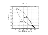
図14はHFE7200とEMCの混合溶媒に関する気液相図である。この系の場合も、ΔT(B.P.)が約30℃で狭いために、EMCが多い範囲でのHFE7200の蒸気相中の容積%が低くなっている。さらに、HFE7200は分子中のF/H比が1.8 でHFE7100のF/H比が3よりも低いために、消火作用が低く、この系はEMCが20容量%と低い混合割合においても引火する。
【0097】
以上のことから、不燃性フッ素溶媒と可燃性溶媒との混合溶媒の不燃化は、フッ素溶媒の高い蒸気による窒息作用が寄与していると考えられる。そのため、フッ素溶媒との沸点の差ΔT(B.P.)が広いものほど引火点のなくなる範囲が広くなる。
【0098】
[実施例40〜43]
表7に示す組成の溶媒としてHFE7100にTGM(トリグライム)を混合した溶媒のリチウム塩、LiBETIの濃度に対する導電率の変化を調べた。
【0099】
これらの結果を、図15に示した。図示した様に、TGMの混合割合により導電率の極大点は高塩濃度側へ移行し、更に、それらの絶対値もTGMの混合割合にしたがって大きくなった。
【0100】
【表7】
[実施例44〜47]
表8に示す組成の溶媒としてHFE7100にDME(ジメトキシエタン)を混合した溶媒のリチウム塩,LiBETIの濃度に対する導電率の変化を調べた。
【0102】
これらの結果を、図16に示した。図示した様に、この系の場合もDMEの混合割合により導電率の極大点は高塩濃度側へ移行し、更に、それらの絶対値もDMEの混合割合にしたがって大きくなった。
【0103】
【表8】
[実施例48〜53]
表7に示す組成の溶媒としてHFE7100にDMEを20容量%混合した溶媒に実施例48:PC(プロピレンカーボネート),実施例49:CIEC(クロロエチレンカーボネート),実施例50:DMVC(4,5−ジメチルビニレンカーボネート),実施例51:EC(エチレンカーボネート),実施例52:BC(ブチレンカーボネート)及び実施例53:TFPC(トリフロロプロピレンカーボネート)を0.5 モル/リッター添加した溶液に、リチウム塩としてLiBETIを溶解した電解液のリチウム塩濃度に対する導電率の変化を調べた。
【0105】
この結果を図17に示す。図から分かる様に、これらの高誘電率の溶媒を HFE7100−DME系電解液に添加すると導電率の絶対値はやや低下するが、リチウム塩濃度に対する極大点は0.4M(モル/リッター)と高誘電率溶媒を添加しないHFE7100−DME系の極大値0.6Mに比べ低くなっている。即ち、高誘電率溶媒を添加することにより、高価なリチウム塩の必要量を低く抑えることができる。
【0106】
[実施例54〜56]
溶媒としてHFE7100に非水溶媒としてDMEを10容量%(実施例54),15容量%(実施例55),DMC10容量%とDME10容量%(実施例56)混合した際の電解液のリチウム塩(LiBETI)濃度に対する導電率の変化を調べた。この結果を図18に示す。
【0107】
HFE7100:DME=90:10の混合溶液では、リチウム塩が0.6Mまでしか溶解しなかったが、導電率は0.4Mで極大値0.55mS/cmを示した。これにDMCを混合し3溶媒系とすることによりDMCの混合割合とともに導電率が増加した。また、混合割合が10容量%(HFE7100:DMC:DME=80:10:10)の場合には導電率の極大値は0.8Mまでシフトし、1.15mS/cmを示した。
【0108】
[実施例57,58]
HFE7100に対して以下の混合割合で2種の非水溶媒を混合した電解液を作製し、リチウム塩濃度依存性を調べた。
【0109】
(実施例57):非水溶媒としてEMC15容量%,DME5容量%。
【0110】
(実施例58):非水溶媒としてEMC10容量%,DME10容量%。
【0111】
EMCを混合した場合も、DMCを混合した場合同様に、EMCの混合割合と共に導電率は増加した。しかし、EMCの場合には、HFE7100:EMC:DME=80:10:10容量%の組成において0.6M の塩濃度において導電率の極大値0.9mS/cmを与えた。
【0112】
[実施例59〜62]
HFE7100に1,3−ジオキソラン(DOL)を混合した系に関して同じ評価を行った。この結果を図19に示す。
【0113】
(実施例59):非水溶媒としてDMC10容量%,DOL10容量%。
【0114】
(実施例60):非水溶媒としてDME10容量%,DOL10容量%。
【0115】
DOLとDMCの混合では極大点が0.6Mで0.72mS/cmを示した。また、DOLとDMEの混合では極大点が0.8Mで0.68mS/cmを示した。
【0116】
(実施例61):HFE7100:DMC=80:20,(実施例62):
HFE7100:DEC=80:20にリチウム塩(LiBETI)の濃度を増加させた場合の導電率変化の極大点は0.8M で同じであった。いずれも容量比である。
【0117】
[実施例63〜66]
HFE7100−DEC系に関してDMEの混合効果を調べた。この結果を図20に示す。
【0118】
(実施例63):HFE7100:DEC=80:20,(実施例64):
HFE7100:DEC:DME=80:10:10,(実施例65):HFE7100:DEC:DME=80:15:5,(実施例66):HFE7100:DEC:DME=70:20:10の混合溶媒系に関してリチウム塩濃度に対する変化を調べた。いずれも容量比である。
【0119】
実施例64のDMEを10容量%混合した電解液では、導電率の極大点が0.6Mにシフトした。これまでのことから、DMEを10容量%程度他の非水電解液に混合すると導電率の極大点を低濃度にシフトする効果があることが分かった。
【0120】
[実施例67〜69]
HFE7100とDGM(ジグライム)の混合系に関して導電率を調べた。この結果を図21に示す。
【0121】
(実施例67):HFE7100:GDM=80:20,(実施例68):
HFE7100:GDM=70:30,(実施例69):HFE7100:GDM=60:40の混合溶媒系に関してリチウム塩濃度に対する導電率の変化を調べた。いずれも容量比である。
【0122】
DGMの場合は、20,30容量%の2成分混合系ではリチウム塩(LiBETI)は0.2Mまでしか溶解しなかった。また、40容量%でも0.4Mまでが溶解限界であった。但し、実施例69では2.7mS/cm と高い導電率を示した。
【0123】
[実施例70〜73]
HFE7100−DGMに第3の非水溶媒を混合した混合溶媒系に関してリチウム塩濃度に対する導電率変化を調べた。いずれも容量比である。
【0124】
(実施例70):HFE7100:GDM:DMC=80:10:10。
【0125】
(実施例71):HFE7100:GDM:DME=80:10:10。
【0126】
DMCやDME等の非水溶媒を混合することによって、DGMが10容量%と低い混合割合においても1M以上のリチウム塩溶解能力を得ることが分かった。
(実施例72):HFE7100:GDM:DMC=80:15:5。
【0127】
(実施例73):HFE7100:GDM:DME=80:15:5。
【0128】
実施例71,72で見られた効果は、DMCやDMEが5容量%では得られないことが分かった。これらのことから、DGMはリチウムイオンの解離性を促進する役割の溶媒として好適であることが分かる。
【0129】
[実施例74〜76]
HFE7100にTGM(トリグライム)を混合した混合溶媒系に関してリチウム塩濃度に対する導電率を調べた。この結果を図22に示す。いずれも容量比である。
【0130】
(実施例74):HFE7100:TGM=80:20。
【0131】
(実施例75):HFE7100:TGM=70:30。
【0132】
(実施例76):HFE7100:TGM=60:40。
【0133】
TGMの場合は2成分混合溶媒系でも、リチウム塩LiBETIは0.6M 以上溶解した。しかし、TGMの混合割合が40容量%に高くなると、やはり溶解の限界が存在することが分かった。
【0134】
[実施例77〜84]
HFE7100−TGM系に第3の非水溶媒を混合した場合の導電率を調べた。この結果を図23に示す。いずれも容量比である。
【0135】
(実施例77):HFE7100:TGM:DMC=80:15:5。
【0136】
(実施例78):HFE7100:TGM:DMC=80:10:10。
【0137】
TGMとDMCを混合した場合は、DMCの混合量に対して導電率は低下する傾向があることが分かった。また、HFE7100−TGM−DMC系では0.4Mから1.0M までのリチウム塩濃度に対する導電率の変化が平坦になり電池の特性上安定した特性が期待される。
【0138】
(実施例79):HFE7100:TGM:DME=80:15:5。
【0139】
(実施例80):HFE7100:TGM:DME=80:10:10。
【0140】
TGMとDMEを混合した場合には、0.6M のリチウム塩濃度において導電率の極大値を示した。また、これらの極大値はDMEの混合割合に関係なく1.7mS/cm程度で同じであった。更に、この数値はHFE7100:TGM=80:20の系の極大値1.35mS/cm よりもかなり高くなっており、DMEを混合することによってHFE7100−TGM系の導電率は高くすることができることが分かる。
【0141】
(実施例81):HFE7100:TGM:DGM=80:10:10。
【0142】
TGMとDGMを混合した場合には、リチウム塩は0.8M までしか溶解しなかった。但し、0.6M における導電率の極大値は1.55mS/cmでHFE7100:TGM=80:20の系の極大値1.35mS/cm よりも高くなっており、DGMを混合することによってもHFE7100−TGM系の導電率を高くすることができることが分かった。
【0143】
(実施例82)
電解液としてHFE7100:TGM:ClEC=80:15:5とした溶媒にリチウム塩を0.8M 溶解した溶液を用い、コバルト酸リチウムを正極材料に、黒鉛炭素を負極に用いた18650型の捲回電極−円筒型電池を作製した。
【0144】
(実施例83)
電解液としてHFE7100:TGM:PC=80:15:5とした溶媒にリチウム塩を0.8M 溶解した溶液を用い、上記と同じ電池を作製した。
【0145】
この電池の2回目の放電曲線を図24に示した。
【0146】
(実施例84)
電解液としてHFE7100:DME=90:10とした溶媒にリチウム塩を0.6M 溶解した溶液を用い、正極にマンガン酸リチウム、負極に非晶質炭素を用い、前述の実験セルを作製した。このセルの充放電サイクル試験結果を図25に示す。50サイクル後の容量低下率は最大初期容量の20%以内であった。
【0147】
[実施例85]
図26は実施例1〜84に記載のリチウム2次電池を用いた電気自動車の駆動システム構成を示す図である。
【0148】
通常のガソリン車と同じようにキースイッチを投入し、アクセルを踏むとアクセル踏み角度に応じて、電動機のトルクまたは回転を制御するようにしている。アクセルを戻したときには、エンジンブレーキに相当する回生ブレーキを動作させ、ブレーキ踏み込み時には回生ブレーキ力をさらに増加させている。シフトレバー信号では車の前進・後進切換えを行い、変速比は常に一定としている。制御方式としては、誘導電動機を用いたIGBTベクトル制御インバータ方式を採用し、電源電圧はIGBT耐電圧から336Vとした、本実施例では、出力を自動車としての動力性能(加速・登坂性能)から最大出力45kW,最大トルク176N・mとし、最高速度仕様から定格出力を30kWとした。主要制御項目としては、車の前進・後進制御,回生制御のほかに、フェイルセイフ制御を行うようにしている。
【0149】
電動機の小型・軽量化によって熱密度が大きくなるので、効率の良い冷却構造とすることが重要になる。一般的な空冷式では電動機の温度上昇が高くなるので、一般のエンジンと同しように水冷式にした。冷却水路は電動機本体を覆うアルミニウム製フレーム内に設け、温度上昇シミュレーションによって最適な形状とした。冷却水はフレームの水路の給水口から流入し、電動機本体の熱を吸収したのち排出され、循環経路中のラジエータによって冷却される。このような水冷構造とすることにより、冷却性能を空冷に対し3倍程度向上することができた。
【0150】
インバータは、パワー素子にはIGBTが使用されており、最高出力時は最大数キロワット程度の発熱がある。このほかにもサージ吸収用の抵抗,フィルタコンデンサなどからも発熱があり、これらの部品を許容温度以下に抑え、効率よく冷却することが必要である。特にIGBTの冷却が問題であり、冷却方式としては、空冷,水冷,油冷などが考えられる。ここでは、取り扱いが容易で効率の良い冷却ができる強制水冷方式とした。
【0151】
本実施例における電源としてリチウム2次電池においては図に示す保護回路が形成される。保護回路は過充電,過放電から電池を保護するものである。その保護回路は図27に示す様に各電池のセル電圧を調整するバランス補償回路からなるもので、各電池に設けられるものである。このバランス補償回路はマイクロコンピュータによってコントロールされる。従来のリチウム2次電池においては電解液が可燃性を有するので、サーミスタを各電池に設けて温度又は圧力検出し、それによって監視していたが、本実施例においては火点を電解液に接近させても炎がその液体に燃え移らない引火点を持たない不燃性のものであるので、特別な温度又は圧力の監視を要しないものにしたものである。それによって保護回路として安全機構を少なくすることができたものである。図26に示す様に過放電が検出されれば電源が自動的に開閉できるようになっている。
【0152】
本実施例は誘導電動機を用いた例を示したものであるが、図28に示す様に他に永久磁石型同期電動機及び直流分巻電動機を用いた電気自動車に対しても同様に用いることができるものである。図中、INV(Inverter:インバータ),IM(Induction Motor:誘導電動機),E(Encoder:エンコーダ),SM (Synchronus Motor:同期電動機),PS(Position Sensor:位置検出器),PWM(Pulse Width Modulation:パルス幅変調),DCM(DCMotor:直流電動機),CH(Chopper:チョッパ),N* :速度指令,T* :トルク指令。図において、各段落は制御方式,システム構成及び主要制御パラメータを示している。
[実施例86]
図5は実施例1〜84に記載のリチウム2次電池を用いた夜間電力の電力貯蔵システムを示す構成図である。本電力貯蔵システム例は2000kW×4h,セル容量1000Whとし、電池360個直列接続、24列並列接続の例を示したものである。本実施例においても実施例85と同様に過充電及び過放電から電池を保護する必要があり、図27に示す保護回路が監視・バランス補償回路を有するものである。
【0153】
本実施例においても前述と同様に電池が保護されるものである。
【0154】
本実施例は大容量の電力貯蔵を目的としたものであるが、家庭用のエアコンデショナー,電気温水器等においても有効である。
【0155】
【発明の効果】
本発明によれば、民生用途のリチウム2次電池から電力貯蔵用途や電気自動車用途の大容量リチウム2次電池を本質的に不燃化でき、抜本的に安全性の向上した信頼性の高い各種用途に応じたリチウム2次電池を提供できる。更に、従来この電池の安全性確保のためや更なる軽量化,小型化が期待できる。備えられている電池内の保護機構や外部の保護回路等を軽減ないし、ないものが得られる顕著な効果が達成できる。また、電解液が不燃性であることにより、製造現場に貯蔵できる電解液の量的な規制も緩和されるので、現在よりも多量の電解液を製造用にストックすることができ、製造の調整や在庫の調整等にも波及するメリットがある。
【図面の簡単な説明】
【図1】本発明の一実施例に係る不燃性電解液のリチウム塩濃度及び溶媒組成と導電率との関係を示す図である。
【図2】本発明の一実施例に係る不燃性電解液のリチウム塩の種類とそれらの塩濃度と導電率との関係を示す図である。
【図3】実施例19〜23に係る円筒型電池の縦断面図である。
【図4】実施例24〜28に係る円筒型大容量電池の縦断面図である。
【図5】引火点と可燃溶媒との関係を示す線図である。
【図6】実施例31に係る円筒型電池の縦断面図である。
【図7】実施例31の円筒型電池での負荷特性を示す図である。
【図8】実施例31の円筒型電池の高電流値放電における放電電圧曲線の比較を示す図である。
【図9】試験電池の縦断面図である。
【図10】実施例33〜36の各種添加溶媒の負荷特性の向上効果を示す図である。
【図11】本発明に係るLiPF6 無機リチウム塩添加量の負荷特性の向上効果を示す図である。
【図12】温度とEMC混合割合との関係を示す線図である。
【図13】温度とDMC混合割合との関係を示す線図である。
【図14】温度とEMC混合割合との関係を示す線図である。
【図15】導電質とLiBETI塩濃度との関係を示す線図である。
【図16】導電質とLiBETI塩濃度との関係を示す線図である。
【図17】導電質とLiBETI塩濃度との関係を示す線図である。
【図18】導電質とLiBETI塩濃度との関係を示す線図である。
【図19】導電質とLiBETI塩濃度との関係を示す線図である。
【図20】導電質とLiBETI塩濃度との関係を示す線図である。
【図21】導電質とLiBETI塩濃度との関係を示す線図である。
【図22】導電質とLiBETI塩濃度との関係を示す線図である。
【図23】導電質とLiBETI塩濃度との関係を示す線図である。
【図24】電池電圧と放電容量との関係を示す線図である。
【図25】電池容量とサイクル数との関係を示す線図である。
【図26】本発明に係る電気自動車の駆動システム構成図である。
【図27】本発明に係る保護回路図である。
【図28】本発明に係る電気自動車の制御システム図である。
【図29】本発明に係る電力貯蔵システム図である。
【符号の説明】
1…銅箔集電体、2…負極、3…負極端子、4…アルミ集電体、5…正極、6…正極端子、7,11…セパレーター、8…負極インシュレータ、9…負極及び負極活物質、10…正極及び正極活物質、12…内圧開放弁、13…電池正極蓋、14,19…電池缶、15…レーザ溶接部、16…絶縁板、17…負極リード、18…正極リード、20…正極蓋、21…正極インシュレータ、22…円形負極、23…円形正極、24…円形セパレーター、25…負極端子、26…正極端子、27…テフロン製締め付けネジ。[0001]
BACKGROUND OF THE INVENTION
The present invention relates to a nonaqueous electrolytic solution using lithium ions as movable ions, a lithium secondary battery using the nonaqueous electrolytic solution, an electrolytic solution thereof, and an electric device.
[0002]
[Prior art]
A lithium secondary battery using a non-aqueous electrolyte has a high voltage and a high energy density, is excellent in storage performance and low-temperature operability, and is widely used in portable consumer electronic products. In addition, research and development for increasing the size of this battery and using it as a nighttime power storage device for electric vehicles and homes are actively conducted.
[0003]
However, many of the solvents used for these have a low flash point and a high flammability. Therefore, there is a risk of ignition, explosion, etc. due to overcharge or heating. Therefore, recently, proposals for ensuring the safety of this battery are increasing. For example, Japanese Patent Application Laid-Open No. 7-192762 discloses that combustibility is reduced by mixing a halogenated formate which can be expected to have a combustion suppressing effect with a cyclic carbonate. JP-A-8-45544 discloses that halogenated esters are mixed. However, halogenated formic acid esters and halogenated esters have a lower flash point than non-halogenated cyclic carbonates. In some cases, it is unlikely that sufficient flame retardancy has been achieved. As other means, JP-A-4-184370 and JP-A-8-88023 describe that the electrolyte contains a phosphate ester that is expected to have a self-extinguishing action. There is a tendency to be slightly inferior.
[0004]
The above is an example in which a solvent having high self-extinguishing properties or a solvent having a fire extinguishing action is used for the non-aqueous electrolyte. However, using a non-flammable fluorine compound as a non-aqueous electrolyte solvent is a lithium secondary battery. Is the ultimate means of making incombustible. Regarding the use of a fluorine compound, JP-A-9-293533 discloses that a fluorinated alkane is mixed with a solvent in a range of 0.5 to 30% by weight to make it flame retardant. The action of the fluorinated alkane in this example is a fire extinguishing action due to the suffocation of the mixed gas by these low boiling point fluorine compounds, and it is difficult to say that it is an electrolytic solution using a nonflammable solvent even from the mixing ratio. Japanese Patent Laid-Open No. 9-293533 discloses that a fluorine compound having a boiling point of 25 ° C. or less is contained in the battery, and the fluorine compound is vaporized prior to the flammable solvent when the battery is exposed to a high temperature. , A method of making flame retardant by suffocating combustion of a combustible solvent with the vapor is disclosed. In this example, the nonflammable solvent is used in a form separated from the electrolytic solution, and the nonflammable solvent is not intended to be used as the electrolytic solution.
[0005]
[Problems to be solved by the invention]
As described above, incombustibility of the electrolyte is important for establishing safety of the lithium secondary battery. However, the characteristics of non-flammable solvents, which are representative of non-flammable liquids, are generally poor in solubility of lithium salts due to their small dipole moment and low dielectric constant. In addition, the lithium salt has a good dissociation property and a low compatibility with a non-aqueous solvent having a large dipole moment, and these and the non-flammable solvent cannot be mixed, resulting in separation into two layers. Thus, the nonflammable solvent does not exhibit any physical properties required for the electrolytic solution. However, it is indispensable to solve the problem of electrolyte flammability, which is the only drawback of the lithium secondary battery, in order to increase the size of the battery and spread it to electric vehicles and household applications.
[0006]
An object of the present invention is to provide a lithium secondary battery, an electrolyte solution thereof, and an electric device that eliminate the dangers of explosion, ignition, smoke, etc. due to high temperature, heating, overcharge, internal short circuit, and the like.
[0007]
[Means for Solving the Problems]
The present invention has a conductivity of 0.05 ms / cm or more, preferably 0.1 to 3 ms / cm, more preferably 0.2 to 2.5 ms / cm, and has no flash point in the JIS-K2265 test. A lithium secondary battery is characterized by having a water electrolyte.
[0008]
The present invention relates to a lithium secondary battery having a negative electrode capable of occluding and releasing lithium, a positive electrode capable of occluding and releasing lithium, a non-aqueous electrolyte containing a separator and a lithium salt, and the non-aqueous electrolyte is a non-aqueous electrolyte. A mixed solution of an ion conductive solvent, preferably a non-flammable solvent having extremely flame retardancy, and a lithium ion conductive solvent, wherein the electrolyte solution has no flash point in JIS-K2265 test. To do. The ratio of the nonionic conductive solvent and the ionic conductive solvent in the present invention is such that the latter does not have the above flash point by setting the latter amount to 10 to 40% by volume.
[0009]
The present invention is characterized in that, in the lithium secondary battery, the nonaqueous electrolyte contains 20% by volume or more of a nonionic conductive solvent and a lithium ion conductive solvent.
[0010]
The present invention is characterized in that the non-aqueous electrolyte includes a mixed solution of a non-ion conductive solvent and a lithium ion conductive solvent, and the conductivity of the electrolyte is 0.1 to 3 ms /
[0011]
The present invention is characterized in that the nonaqueous electrolytic solution includes a mixed solution of a nonionic conductive solvent and a lithium ion conductive solvent, and the dipole moment of the lithium ion conductive solvent is 3 Debye or less. It is in a lithium secondary battery.
[0012]
In the present invention, the non-aqueous electrolyte includes a mixed solution of a non-ion conductive solvent and a lithium ion conductive solvent, and the lithium ion conductive solvent has a dipole moment of less than 3 Debye and 3 or more Debye. What is included in a lithium secondary battery.
[0013]
The present invention resides in a lithium secondary battery, wherein the nonaqueous electrolytic solution includes a nonionic conductive solvent and a lithium ion conductive solvent, and the lithium salt includes an organic lithium salt and an inorganic lithium salt.
[0014]
The present invention includes a nonionic conductive solvent and a lithium ion conductive solvent, has a conductivity of 0.1 ms /
[0015]
Here, the nonionic conductive solvent according to the present invention is abbreviated as a nonflammable solvent and will be described hereinafter. Non-flammable solvents do not dissolve lithium salts, but up to a certain limit depending on the physical properties of non-flammable solvents, ionic conductive solutions in which lithium salts composed of non-aqueous solvents with a low dipole moment are dissolved and dissociated. It was found that they can be mixed or dispersed in a form that is mixed, and this mixed solution functions as an electrolytic solution.
[0016]
The electrolyte solution according to the present invention is also referred to as a nonflammable electrolyte solution and will be described hereinafter.
[0017]
The nonflammable electrolytic solution of the present invention is a solution in which a nonaqueous solvent having a dipole moment value of 3 Debye or less dissolved or dissociated in a fluorinated solvent is dissolved or dispersed. As a specific example of a fluorinated solvent that can be used as an electrolyte, a lithium secondary battery having extremely high safety can be obtained.
[0018]
[Chemical Formula 3]
(Wherein m represents an integer of 2 to 8, n represents an integer of 1 to 5, and the relationship between m and n is m ≧ ((6n + 1) / 4)). Can be used. These solvents have a dipole moment value obtained from molecular orbital calculation of about 2 Debye, and the dipole moment value of the non-aqueous solvent mixed from the viewpoint of improving the compatibility is also close to or less than 2 Debye. Preferably, the non-aqueous solvent has a dipole moment of at most 3 Debye.
[0020]
The fluorinated solvent in the nonflammable electrolyte solution of the present invention will be hereinafter referred to as a nonflammable fluorinated solvent. Examples of the nonflammable fluorinated solvent include 1 selected from perfluorobutyl methyl ether, perfluorobutyl ethyl ether, perfluoropentyl methyl ether, perfluoropentyl ethyl ether, perfluoroheptyl methyl ether, perfluoroheptyl ethyl ether, and the like. One or more solvents are used. In particular, the above two are preferable. Also,Ion conductive solventExamples of non-aqueous solvents include dimethyl carbonate, ethyl methyl carbonate, diethyl carbonate, methyl propyl carbonate, ethyl propyl carbonate, dipropyl carbonate, bis (trifluoroethyl) carbonate, bis (pentafluoropropyl) carbonate, trifluoroethyl methyl. Carbonate, pentafluoroethyl methyl carbonate, heptafluoropropyl methyl carbonate, perfluorobutyl methyl carbonate, trifluoroethyl ethyl carbonate, pentafluoroethyl ethyl carbonate, heptafluoropropyl ethyl carbonate, perfluorobutyl ethyl carbonate, etc.
[0021]
[Formula 4]
(Wherein p is an integer of 2 to 10, R1Is hydrogen or an alkyl group having 1 to 3 carbon atoms, R2Is a non-aqueous solvent selected from fluorinated oligomers represented by 1 to 3 carbon atoms), and the value of the dipole moment is preferably 3 debyes or less. The fluorinated solvent and the ion conductive non-aqueous solvent form a compatible state.
[0023]
As an organic lithium salt, for example, LiCFThreeSO2, LiN (CFThreeSO2)2, LiN (CFThreeSO2) (CFThreeCF2CF2CF2SO2), LiN (CFThreeCF2SO2)2, LiC (CFThreeSO2)2, LiC (CFThreeCF2SO2)2, Li [PFFour(CF (CFThree)2)] Can be used.
[0024]
As an inorganic lithium salt, LiPF6, LiBFFour, LiF, LiBr, LiI, LiCl, LiBr, LiClOFourOne or more selected from among these are used. When these lithium salts are dissolved in the mixed solvent of the non-flammable solvent and the non-aqueous solvent, the lithium salt is dissolved and dissociated by the non-aqueous solvent, and the lithium ion and the counter anion are surrounded by the solvated non-aqueous solvent, and fluorine A state compatible with the solvating solvent is realized. Furthermore, when the concentration of the lithium salt to be mixed increases, the non-aqueous solvent cannot form a sufficient solvation zone with lithium ions or counter anions, and a nonflammable solvent in contact with the lithium ions or counter anions is formed, resulting in solvent system energy. Destabilizes, so some solvates come together to form a larger solvation sphere, and non-flammable solvent molecules do not directly contact the ions. Macroscopically, nonaqueous solvent molecules containing ions form micelle patterns in a fluorine solvent, and a conductive solution is dispersed in a nonconductive solvent (nonflammable solvent).
[0025]
A solution in which the non-flammable solvent molecules and the non-aqueous solvent molecules in which the lithium salt is dissolved and dissociated in the above-described compatible state or dispersed state is mixed can be used as the non-flammable electrolyte. However, if the concentration of the lithium salt exceeds a certain limit value determined by the compatibility of the non-flammable solvent molecule and the non-aqueous solvent molecule, the solubility of the non-aqueous solvent and the lithium salt, etc., the mixed solution will change from the non-flammable solvent molecule to the lithium salt. As a result, the non-aqueous solvent solution in which is dissolved is separated and is no longer an electrolyte solution. As the nonflammable solvent, perfluorobutyl methyl ether or perfluorobutyl ethyl ether which is a fluorinated solvent is preferable.
[0026]
Examples of the negative electrode include non-graphitizable carbon, natural or artificial graphite carbon, tin oxide, silicon or germanium compound, lithium metal or lithium alloy, and the like as the negative electrode active material. In addition, the positive electrode includes a lithium composite oxide of transition metal such as cobalt, nickel, manganese, or a lithium site of the lithium composite oxide or a part of the transition metal site of cobalt, nickel, manganese, aluminum, boron, magnesium, iron. Examples of suitable positive electrode materials include compounds substituted with copper, iron complex compounds such as ferrocyan blue and Berlin green, and the like.
[0027]
A microporous polymer film is used for the separator. Examples thereof include nylon, cellulose, nitrocellulose, polysulfone, polyacrylonitrile, polyvinylidene fluoride, polypropylene, polyethylene, and polybutene.
[0028]
The battery shape is not limited to a specific shape. For example, a battery having a cylindrical shape, a coin shape, a rectangular battery, or the like can be used. Further, there is no particular limitation on the battery capacity, and the battery capacity can be applied from a few Wh for consumer use to a few hundred Wh for household power storage and electric vehicles.
[0029]
In the present invention, the electrolyte solution does not have a flash point, and the following electrolyte solution is used as a result of intensive studies on a non-aqueous electrolyte composition containing a lithium salt for the purpose of improving load characteristics.
[0030]
(A) 40 to 95% by volume of a fluorinated solvent,
(B) 5 to 60% by volume of a low dipole moment solvent having a dipole moment of less than 3 Debye obtained from semiempirical molecular orbital calculations; and
(C) 0.1 to 10% by volume of a high dipole moment solvent having a dipole moment obtained by semi-empirical molecular orbital calculation of 3 debyes or more,
(D) 0.2 to 1.2 mol / liter of an organic lithium salt and
(E) The inorganic lithium salt has one or both of 0.005 to 0.5 mol / liter of (d) and (e), and particularly has a composition having no flash point in the flash point test of JIS 2265 as an electrolyte. Is. As the fluorinated solvent, methyl perfluoroalkyl ether in which n represented by (Chemical Formula 5) is represented by 4 to 12 can be used.
[0031]
[Chemical formula 5]
In addition, chain low dipole moment solvents of less than 3 debyes include dimethyl carbonate (DMC), ethyl methyl carbonate (EMC), diethyl carbonate (DEC), methyl propyl carbonate (MPC), methyl trifluoroethyl carbonate (MTFEC). ), Dimethoxyethane (DME), or triglyme (TGM) can be used singly or in combination. High dipole moment solvents of 3 debyes or more include ethylene carbonate (EC), propylene carbonate (PC), trifluoropropylene carbonate (TFPC), chloroethylene carbonate (ClEC), vinylene carbonate (VC), butylene carbonate (BC) , Dimethyl vinylene carbonate (DMVC), and γ-butyrolactone (GBL) can be used by mixing one or more solvents. As the organic lithium salt, those described above are used. As the inorganic lithium salt, those described above are used.
[0033]
The present invention contains 65% by volume or more of methyl perfluorobutyl ether as a fluorinated solvent, and less than 25% by volume of one or more of dimethyl carbonate, ethyl methyl carbonate, diethyl carbonate, dimethoxyethane, and triglyme as a low dipole moment solvent. In the range of 0.1 to 10% by volume as a solvent with a high dipole moment, and LiN (SO2CF2CFThree)2At a concentration of 0.2 to 1.2 mol / liter, and LiPF as an inorganic lithium salt6Is in the range of 0.005 to 0.5 mol / liter, and preferably in a lithium secondary battery using a nonflammable electrolytic solution having a composition having no flash point in the flash point test of JIS 2265.
[0034]
The requirements to be satisfied by the fluorinated solvent used in the electrolyte solution are that it is a non-flammable solvent having no flash point and is compatible with a solvent having a low dipole moment or a solvent having a high dipole moment. In the present invention, the fluorinated solvent does not particularly require the lithium salt solubility required for a general electrolyte solution solvent. Accordingly, many chain fluorinated solvents can be used as non-flammable solvents, and perfluoroalkanes, semifluoroalkanes, or derivatives obtained by introducing chlorine or bromine into these can also be used. However, considering the environmental impact and toxicity, it is hard to say that it is a good material. Hydrofluoroether introduced as an environmentally friendly alternative cleaning agent for fluorocarbon cleaners does not have these problems and is not expensive compared to electrolyte solvents, and is suitable as a nonflammable solvent for nonflammable electrolytes. is there. That is, as the fluorinated solvent, it is preferable to use methyl perfluoroalkyl ether represented by the above formula (5) (wherein n represents an integer of 4 to 12). These solvents include methyl perfluorobutyl ether, methyl perfluoropentyl ether, methyl perfluorohexyl ether, methyl perfluoroheptyl ether, methyl perfluorooctyl ether, methyl perfluorononyl ether, methyl perfluorodecyl ether, methyl perfluorode Examples include undecyl ether and methyl perfluorododecyl ether.
[0035]
Since fluorinated solvents generally have a small dipole moment, a chain-like low dipole moment solvent is more compatible as the first solvent mixed therewith. Such a solvent is as described above.
[0036]
The mixed solvent of these hydrofluoroethers and a low dipole moment solvent depends on the type and mixing ratio of the organic lithium salt, but even in the region where the fluorinated solvent is 80% by volume or more, 1. It can dissolve up to about 2M. These soluble organic lithium salts are as described above. Of these, LiN (SO2CF2CFThree)2, LiC (SO2CF2CFThree)Three, LiC (SO2CFThree)Three, Li [PFFour(CF (CFThree)2However, the present battery using aluminum for the positive electrode current collector is preferable because of its low reactivity with aluminum at a high potential.
[0037]
A nonflammable electrolyte can be realized by using the above constituent materials, but in order to further improve the load characteristics, a film for reducing the insertion / extraction resistance of lithium ions at the active material interface during charge / discharge is provided. is necessary. Reaction products in the vicinity of the electrode of the solvent called SEI (Surface Electrode Interface) (for example, J. Electrochemical Soc., P. 2882, vol. 142 (1995), etc.) are present in the electrolyte. The nature of the compound depends on the kind of the compound having high properties, the kind of the mixed solvent in which these compounds react and the mixing ratio. It is considered that the SEI sufficient to maintain the load characteristics is not obtained with the electrolyte of the above constituent materials. Therefore, a solvent having a high dipolar moment and a high coordination property with lithium ions was mixed as a precursor of SEI. When the amount of the solvent having a high dipole moment is increased, the electrolytic solution causes phase separation and cannot be used. Therefore, addition in the range of 0.1 to 10 volume percent is preferable. Furthermore, by adding an inorganic lithium salt which has a very low solubility in a fluorinated solvent or a fluorinated solvent mixture alone to this composition, the load characteristics are further stabilized. As the inorganic lithium salt to be added, the above-mentioned compounds can be used. In particular, when an aluminum current collector is used for the positive electrode, a fluorine-containing compound capable of forming an electrochemically stable film on the aluminum surface. LiPF6, LiBFFourAnd LiF are preferred. Since these inorganic lithium salts are not highly soluble, addition in the range of 0.005 to 0.5 mol / liter is suitable.
[0038]
According to the present invention, in an electric device using a lithium secondary battery as a power source, the protection means against overcharge and overdischarge of the secondary battery is free to detect the temperature and pressure of the battery, and detects the voltage or current of the battery. And control means for opening and closing the power supply based on the detected value.
[0039]
DETAILED DESCRIPTION OF THE INVENTION
[Examples 1 to 9, Comparative Example 1]
Nonafluorobutyl methyl ether (trademark: HFE7100) manufactured by Sumitomo 3M Limited as a nonflammable fluorine solvent, and the dipole moment obtained from semiempirical molecular orbital calculation (MOPAC) is 2.37 debye. Using ethyl methyl carbonate (EMC) as the non-aqueous solvent, the dipole moment obtained in the same manner is 0.887 debye. As the lithium salt, bistrifluoromethylsulfonylimide (LiTFMSI) was used.
[0040]
[Table 1]
The lithium salt concentration and solubility / mixability of the electrolyte solutions of Examples 1 to 9 and the electrolyte solution of Comparative Example 1 in the solvent mixing ratio shown in Table 1 were evaluated.
[0042]
FIG. 1 is a diagram showing the relationship between the lithium salt concentration and the change in conductivity. As shown in the figure, it has been found that the conductivity is improved as the mixing ratio of EMC is increased. Further, it was found that when the mixing ratio of EMC was 50% by volume or more, no decrease in conductivity was observed even when the lithium salt concentration exceeded 1M (mol / liter), and more LiTFSI could be dissolved. In these Examples and Comparative Examples, no dispersion of the nonaqueous electrolytic solution in the fluorine solvent or separation from the fluorine solvent was observed in the evaluated lithium salt concentration region. That is, the electrolyte solution composed of HFE7100 and EMC can prepare a compatible electrolyte solution at almost all mixing ratios. Even when the mixing ratio of HFE7100, which is a highly nonflammable and preferable mixing region, is 40% by volume or more, sufficient conductivity is obtained. (Conductivity about one-third that of the electrolyte solution of Comparative Example 1 using an EMC-only non-aqueous solvent at a lithium salt concentration of 0.95 M).
[0043]
[Examples 10 to 14, Comparative Examples 2 to 5]
Table 2 shows the results of changing the type of the non-aqueous solvent with the mixing ratio of the nonflammable fluorinated solvent HFE7100 being constant at 80% by volume and the mixing ratio of the non-aqueous solvent being 20% by volume.
[0044]
[Table 2]
As shown in Table 2, the compatibility between the solvents of Examples 10 to 14 and Comparative Examples 2 to 5, the mixed state of the electrolytic solution, and the conductivity were evaluated. Here, DMC is dimethyl carbonate, DEC is diethyl carbonate, TFEMC is trifluoroethyl methyl carbonate, BTFPC is bistrifluoropropyl carbonate, DOL is 1,3-dioxolane, PC is propylene carbonate, EC is ethylene carbonate, GBL is γ- Butyrolactone, BC represents butylene carbonate.
[0046]
As can be seen from this table, the solvents of Comparative Examples 2 to 5 having a dipole moment greater than 3 Debye, that is, PC, EC, GBL, and BC are not compatible with the nonflammable solvent HFE7100. From this, it is considered that the difference in polarity of the solvent greatly affects the compatibility. Furthermore, even if the dipole moment is a solvent smaller than 3 Debye, a cyclic molecule such as DOL (1.256 Debye) is dispersed in a non-flammable solvent. Moreover, even if it is a chain | strand-shaped solvent, when a dipole moment will become large like BTFPC (2.719 Debye), the solubility of lithium salt will fall. From the above, it is preferable that the mixed solvent for the fluorine-based nonflammable solvent has a dipole moment of 3 Debye or less.
[0047]
[Examples 15 to 18]
FIG. 2 is a diagram showing the relationship between the concentration dependency related to the solubility of various lithium salts in a mixed solvent of 80% by volume of HFE7100 and 20% by volume of EMC and the conductivity of these electrolytes. As a lithium salt, Example 15 is bispentafluoroethylsulfonyliomide (LiBETI) manufactured by Sumitomo 3M Limited, Example 16 is perfluorobutylmethylsulfonylimide (LiFBMSI) manufactured by Central Glass, and Example 17 is hexagonal. Lithium fluorophosphate (LiPF6), Example 18 is lithium tetrafluoroborate (LiBF)Four). In the figure, the case where the plot disappears in the middle is that the nonflammable solvent and the non-aqueous solvent electrolyte are separated and cannot be measured.
[0048]
As shown, this mixed solvent system uses LiPF.6And LiBFFourIt was found that organic salts such as LiTFSI, LiBETI, and LiFBMSI having a fluorine chain have higher solubility and dissociation properties and better electrical conductivity than inorganic salts such as. This is because these dissociated anions are highly targeted and the dipole moment is almost zero (calculated value is PF).6 -Is 0.001, BFFour -In addition, the molecular radius is small, the chargeability is high, and the affinity with a nonflammable fluorine solvent having a low dielectric constant is considered to be reduced.
[0049]
In contrast, the dissociated anion of an organic salt has a dipole moment (calculated value is TFSI-Is 1.23, BETI-1.103, FBMSI-Is 8.468 debye), the molecular radius is large, and the organic anions shown here have a fluorine chain, so that good affinity with non-flammable fluorine solvents contributes to high solubility. It is thought that. That is, the organic lithium salt is a more preferable material as the electrolyte of the nonflammable electrolyte. Among them, LiTFSI having a short fluorine chain length has good diffusibility of the counter anion and is excellent as an electrolyte for a nonflammable electrolyte.
[0050]
[Examples 19 to 23, Comparative Example 6]
[0051]
[Table 3]
Table 3 shows the results of producing batteries of Examples 19 to 23 using noncombustible electrolytes of various compositions and Comparative Example 7 using conventional electrolytes and evaluating battery characteristics and safety. It is. HFE7200 represents 3M non-flammable solvent, nonafluorobutyl ethyl ether.
[0053]
FIG. 3 is a cross-sectional view of a cylindrical battery having an outer diameter of 18 mm and a height of 65 mm in this example. The negative electrode
14 and this lid were sealed by laser welding 15 and produced.
[0054]
The
[0055]
Similarly, graphite powder having an average particle diameter of 8 μm having rhombohedral crystals of 1 to 20% by weight as a negative electrode active material and the balance being hexagonal crystal, and 10 wt% of PVDF as a binder were added, and N-methyl-2- Pyrrolidone was added and mixed to prepare a negative electrode mixture slurry.
[0056]
The positive electrode mixture was applied to both surfaces of an aluminum foil having a thickness of 20 μm, and then vacuum dried at 120 ° C. for 1 hour. After vacuum drying, the electrode was press-molded with a roller press to a thickness of 195 μm. The amount of mixture applied per unit area is 55mg / cm2Met. The proportion of rhombohedral crystals of the graphite powder can be adjusted by heat treatment at a temperature of 900 ° C. or higher, and it is preferably less.
[0057]
On the other hand, the negative electrode mixture was applied on both sides of a copper foil having a thickness of 10 μm and then vacuum-dried at 120 ° C. for 1 hour. After vacuum drying, the electrode was pressure molded by a roller press to a thickness of 175 μm. The amount of mixture applied per unit area is 25mg / cm2Met.
[0058]
The
[0059]
JIS standard SUS304 or 316 austenitic stainless steel was used for the battery can 14 and the battery
[0060]
Since the initial capacity of Comparative Example 6 was 1300 mAh, the charge / discharge cycle test of each battery was performed up to 300 cycles at 0.5 C (650 mA) based on this capacity. In addition, as a safety test, a fully charged battery is placed horizontally and its center is heated by a direct flame of a gas burner, and a nail with a diameter of 5 mm in the center of the battery is half the battery diameter.
[0061]
[Examples 24-28, Comparative Example 7]
[0062]
[Table 4]
Table 4 shows the batteries of Examples 24-28 using noncombustible electrolytes of various compositions and the electrolyte of Comparative Example 7, lithium manganate as the positive electrode, amorphous graphite as the negative electrode, and 40 micron polyethylene as the separator. Using the film, the large capacity batteries of Examples 24 to 28 and Comparative Example 7 having a diameter of 80 mm and a height of 240 mm having the structure shown in FIG. Is shown. In this battery, the same materials as those in the above-described embodiment were used for the
[0064]
The initial capacity of the battery was 26 to 27 Ah in Examples 24-28 according to the present invention, and 27 Ah in Comparative Example 7. As a result of conducting a charge / discharge test of 300 cycles at a current value of 10A, the battery retention rate was 97% or more. This large battery contains about 100 ml of electrolyte, but in
[0065]
As described above, even when the conductivity is low, the battery capacity and load characteristics are not deteriorated compared to the conventional non-aqueous electrolyte. This suggests that the ion conduction path formed by the ion conductive nonaqueous solvent mixed with the fluorine-based nonflammable solvent is not inhibited. In other words, the conventional non-aqueous electrolyte also conducts ions through the narrow pores of the separator, and the non-flammable solvent also has a similar effect, that is, a liquid separator. It can be thought that there is not. Furthermore, it is estimated that the ion concentration in the ion conduction path is higher than that of the conventional non-aqueous electrolyte, and it can be considered that a very high rate electrolyte solution system is realized as compared with the conventional system.
[0066]
[Example 29]
FIG. 5 is a diagram showing the relationship between the contents of various ion conductive solvents shown in the above-mentioned Examples and the flash point according to the JIS-K2265 test. The non-flammable solvent is HFE7100. As shown in the figure, the content without flash point varies depending on the type of solvent. b.p. is a fluorine point. EMC and DMC are preferably less than 30% by volume, and DME is preferably less than 20% by volume. TGM and DEC are preferably 30% by volume or less.
[0067]
[Example 30]
FIG. 6 is a partial cross-sectional view of a cylindrical battery having a diameter of 18 mm and a height of 65 mm using the non-aqueous electrolyte of the present invention. A negative electrode material paste was prepared by dissolving and kneading 90 parts by weight of a graphite carbon material as a negative electrode active material in N-methylpyrrolidone together with 10 parts by weight of polyvinylidene fluoride (PVDF) as a binder. This negative electrode material paste was applied to both surfaces of a copper foil
[0068]
A mixture of 77.4% by volume of methyl perfluorobutyl ether and 19% by volume of EMC as a fluorinated solvent, and LiN (SO2CF2CFThree)2The
Dissolved at 0.8 mol / liter. Further, 3.6% by weight of EC was dissolved in this solution, followed by LiPF, which is an inorganic lithium salt.6Was dissolved in 0.1 mol / liter to prepare an electrolytic solution A. This electrolytic solution was confirmed to have no flash point in a JIS 2265 creep-open open flash point test.
[0069]
Finally, the electrolytic solution A was poured into the previously prepared battery by vacuum impregnation, and the
[0070]
[Comparative Example 8]
As an electrolyte, LiPF was mixed with a solvent in which 34% by volume of EC and 66% by volume of DMC were mixed.6A battery R1 was prepared using a solution (electrolytic solution R1) in which 1.0 M was dissolved. The flash point of this electrolytic solution in the same test was about 35 ° C.
[0071]
[Comparative Example 9]
As an electrolytic solution, a mixture of 90% by volume of methyl perfluorobutyl ether and 10% by volume of EMC as a fluorinated solvent, and LiN (SO as a lithium salt2CF2CFThree)2Was dissolved in 0.8 mol / liter to prepare an electrolytic solution B, which was injected to prepare a battery R2 of Comparative Example 2. This electrolyte B is obtained from electrolyte A to EC and LiPF.6It is a composition from which is removed. This electrolyte solution B also had no flash point in the flash point test.
[0072]
(Evaluation of load characteristics)
The battery produced as described above was evaluated for load characteristics up to 1400 mA (1C) by increasing the current value from 140 mA to 140 mA in sequence, with 140 mA being 0.1 C (10 hour rate). The charging condition is constant current-constant voltage (CC-CV), and the current value of the constant current increases from 140 mA to 1400 mA sequentially from 140 mA as described above, the voltage of constant voltage charging is 4.1 V, and the termination condition is 15 hours. Or it was 10 mA or less. The results of this test are shown in FIG. Compared to the load characteristics of the battery R1 using the conventional electrolyte R1, the battery R2 using the nonflammable electrolyte B has a significant decrease in discharge capacity at a current of 0.3 C (420 mA) or more. In contrast, EC and LiPF6It was found that the characteristics of the battery using the nonflammable electrolyte solution A with the addition of the slag were significantly improved with respect to the battery R2, although being slightly inferior to the battery R1. The conductivity of these electrolytes is a remarkable change considering that the electrolyte A is 0.7 mS / cm, the electrolyte R1 is 12 mS / cm, and the electrolyte R2 is 0.45 mS / cm. Therefore, these discharge curves at 0.5C were compared with FIG. As can be seen, in this example, the potential drop at the end of discharge is less than that of the battery R2. That is, it is possible to suppress this voltage drop by EC and LiPF.6Is an effect of improving the load characteristics of the electrolytic solution A. This voltage drop is thought to be caused by the adsorption of solvent molecules at the electrode interface and the decrease in the diffusibility of anions and lithium ions, but EC and LiPF.6It is presumed that these obstacles can be alleviated by adding.
[0073]
(Effect of high dipole moment solvent)
The effect of addition was evaluated by changing the type of high dipole moment solvent. A test battery shown in FIG. 9 was prepared using the same positive electrode material and negative electrode material as those of Example 29 with a single-side coated electrode having a diameter of 15 mm, a circular
[0074]
[Example 31]
Electrolytic solution C in which 0.05 g / milliliter of PC (propylene carbonate) is added to electrolytic solution B mixed with 0.05 g / milliliter (weight ratio is 77% by volume of methyl perfluorobutyl ether, 21% by volume of EMC, 2% by volume of PC) as electrolytic solution Using test battery
C1 was produced.
[0075]
[Example 32]
A test battery C2 was prepared using the electrolytic solution D in which the same amount of BC (butylene carbonate) was added instead of PC (weight ratio was 77% by volume of methyl perfluorobutyl ether, 21% by volume of EMC, and 2% by volume of BC).
[0076]
[Example 33]
A test battery C4 was produced using the electrolytic solution F in which the same amount of TFPC (trifluoromethylpropylene carbonate) was added instead of PC (weight ratio was 77% by volume of methyl perfluorobutyl ether, 21% by volume of EMC, and 2% by volume of TFPC).
[0077]
[Comparative Example 10]
A test battery RC1 was produced using the electrolytic solution B.
[0078]
The battery manufactured as described above is gradually increased from 0.05 mA in increments of 0.05 mA up to 5 mA, charged at a constant current-constant voltage (4.1 V) and a final current setting of 5 μA, and discharged at a constant current. The discharge capacities were compared. The result is shown in FIG. It has been found that the addition of a high dipole moment solvent has improved loading characteristics in any material. This is because, considering that the solvent with a high dipole moment is likely to coordinate preferentially to lithium ions, an electrochemical reaction occurs on the active material surface with the solvent with a high dipole moment coordinated to lithium ions. The reaction product is presumed to form a good SEI film on the active material surface. Therefore, it was found that the requirement to be satisfied by the solvent added for improving the load characteristics is high coordination property to lithium ions, and that the molecule has a high dipole moment.
[0079]
Next, the load characteristic improvement effect was evaluated with respect to the amount of inorganic lithium salt added. The test battery shown in FIG. 8 was used as the battery.
[0080]
[Example 34]
Test battery C6 was prepared using electrolytic solution A.
[0081]
[Example 35]
LiPF of electrolyte A6A test battery C7 was prepared using an electrolytic solution H with an addition amount of 0.05 mol / liter.
[0082]
[Example 36]
LiPF of electrolyte A6Test battery C8 was produced using electrolytic solution I with an addition amount of 0.2 mol / liter.
[0083]
[Comparative Example 11]
LiPF of electrolyte A6A test battery CR2 was produced using an electrolytic solution J with an addition amount of 0 mol / liter.
[0084]
The load characteristics of these batteries were evaluated under the same conditions as above, and LiPF6The change of the discharge capacity with respect to the addition amount is shown in FIG. In this way, the inorganic lithium salt LiPF is further added to the high dipole moment solvent.6The load characteristics are further improved by adding. However, inorganic lithium salt LiPF6There was an optimum value for the amount of addition of 0.1 mol / liter in the case of the electrolytic solution A system.
[0085]
(Safety test)
Using the
[0086]
The nail penetration test is (1-1) room temperature, 30 mm / sec, (1-2) room temperature, 5 mm / sec, (1-3) room temperature, 1 mm / sec, (1-4) 60 ° C., 1 mm / sec. Comparison was made under four conditions.
[0087]
[Table 5]
The results are shown in Table 5. The
[0089]
In the overcharge test, the battery was fully charged under the condition of 0.2C-4.1V, and then the current condition of (2-1) 0.5C, (2-2) 1.0C, (2-3) 2.0C It carried out in. The results are shown in Table 6. The nonflammable electrolyte of the present invention has a low conductivity, so
[0090]
[Table 6]
However, the overcharge test was inferior to the conventional electrolyte with high conductivity, but as a result, the overcharge test maintained safety equivalent to or higher than that of the conventional electrolyte. It was confirmed that
[0092]
As described above, in the nonflammable electrolyte system containing a large amount of the fluorinated solvent, the improvement of the load characteristics by adding a very small amount of these high dipole moment solvent and inorganic lithium salt is the first to be found in the present invention. It is considered difficult to drastically improve the load characteristics of the non-flammable electrolyte solution of the present invention such that the non-fluorinated solvent (conventional solvent) that can essentially become a lithium ion medium without the addition of these materials is extremely small.
[0093]
[Examples 37 to 39]
The gas-liquid phase diagram at the time of mixing incombustible solvent and nonaqueous solvent was measured.
[0094]
[Example 37]
FIG. 12 is a gas-liquid phase diagram regarding a mixed solvent of the non-flammable solvent HFE7100 and the non-aqueous solvent EMC. In the case of this mixed solvent, it has already been shown that there is no flash point until the EMC mixing ratio reaches 20% by volume. However, in this mixing ratio, 93% by volume or more of the vapor of this mixed solvent is occupied by the nonflammable solvent HFE7100 from FIG. It can be seen that the flammability of steam is extremely low.
[0095]
[Example 38]
FIG. 13 is a gas-liquid phase diagram regarding a mixed solvent of HFE7100 and DMC. In this system, the vapor pressure of DMC is higher than that of EMC, and the difference in boiling point ΔT (BP) is 30 ° C. (the boiling point of DMC is 90 ° C., the boiling point of HFE 7100 is 60 ° C.), and HFE 7100-EMC Since the ΔT (BP) of the system is narrower than about 50 ° C., the volume% in the vapor phase of HFE7100 in the region where the mixing ratio of DMC is low is low. For this reason, in the HFE7100-DMC system, the range without a flash point is more conspicuous than the HFE7100-EMC system.
[0096]
[Example 39]
FIG. 14 is a gas-liquid phase diagram regarding a mixed solvent of HFE7200 and EMC. Also in this system, since ΔT (BP) is narrow at about 30 ° C., the volume% in the vapor phase of HFE7200 in a range where the EMC is large is low. Furthermore, HFE7200 has a low F / H ratio in the molecule of 1.8 and a F / H ratio of HFE7100 lower than 3, so the fire extinguishing action is low. This system ignites even at a mixing ratio as low as 20% by volume of EMC. To do.
[0097]
From the above, it is considered that the incombustibility of the mixed solvent of the nonflammable fluorine solvent and the combustible solvent is contributed by the suffocation action by the high vapor of the fluorine solvent. For this reason, the wider the difference in boiling point ΔT (BP) from the fluorine solvent, the wider the range where the flash point is eliminated.
[0098]
[Examples 40 to 43]
As a solvent having the composition shown in Table 7, the change in conductivity with respect to the concentration of lithium salt and LiBETI in a solvent in which TGM (triglyme) was mixed with HFE7100 was examined.
[0099]
These results are shown in FIG. As shown in the figure, the maximum point of conductivity shifts to the high salt concentration side due to the mixing ratio of TGM, and the absolute value thereof also increases according to the mixing ratio of TGM.
[0100]
[Table 7]
[Examples 44 to 47]
The change in conductivity with respect to the concentration of lithium salt and LiBETI in a solvent in which DFE (dimethoxyethane) was mixed with HFE7100 as a solvent having the composition shown in Table 8 was examined.
[0102]
These results are shown in FIG. As shown in the figure, also in this system, the maximum point of conductivity shifted to the high salt concentration side due to the mixing ratio of DME, and the absolute value thereof also increased according to the mixing ratio of DME.
[0103]
[Table 8]
[Examples 48 to 53]
Example 48: PC (propylene carbonate), Example 49: CIEC (chloroethylene carbonate), Example 50: DMVC (4, 5-) in a solvent in which 20% by volume of DME was mixed with HFE7100 as a solvent having the composition shown in Table 7 Dimethyl vinylene carbonate), Example 51: EC (ethylene carbonate), Example 52: BC (butylene carbonate) and Example 53: TFPC (trifluoropropylene carbonate) added to 0.5 mol / liter of solution, lithium salt The change in conductivity with respect to the lithium salt concentration of the electrolyte solution in which LiBETI was dissolved was investigated.
[0105]
The result is shown in FIG. As can be seen from the figure, when these high dielectric constant solvents are added to the HFE7100-DME electrolyte, the absolute value of the conductivity slightly decreases, but the maximum point with respect to the lithium salt concentration is 0.4 M (mol / liter). It is lower than the maximum value of 0.6M in the HFE7100-DME system to which no high dielectric constant solvent is added. That is, the required amount of expensive lithium salt can be kept low by adding a high dielectric constant solvent.
[0106]
[Examples 54 to 56]
The lithium salt of the electrolytic solution when 10% by volume (Example 54), 15% by volume (Example 55), 10% by volume of DMC and 10% by volume of DME (Example 56) were mixed with HFE7100 as the solvent and DME as the nonaqueous solvent (Example 56). The change in conductivity with respect to the LiBETI concentration was examined. The result is shown in FIG.
[0107]
In the mixed solution of HFE7100: DME = 90: 10, the lithium salt was dissolved only up to 0.6M, but the conductivity was 0.4M and the maximum value was 0.55 mS / cm. By mixing DMC with this to obtain a three-solvent system, the conductivity increased with the mixing ratio of DMC. Further, when the mixing ratio was 10% by volume (HFE7100: DMC: DME = 80: 10: 10), the maximum value of the conductivity was shifted to 0.8M, indicating 1.15 mS / cm.
[0108]
[Examples 57 and 58]
An electrolyte solution in which two kinds of nonaqueous solvents were mixed with HFE7100 at the following mixing ratio was prepared, and the lithium salt concentration dependency was examined.
[0109]
(Example 57):
[0110]
(Example 58):
[0111]
In the case of mixing EMC, the conductivity increased with the mixing ratio of EMC as in the case of mixing DMC. However, in the case of EMC, a maximum conductivity value of 0.9 mS / cm was given at a salt concentration of 0.6 M in a composition of HFE7100: EMC: DME = 80: 10: 10 vol%.
[0112]
[Examples 59 to 62]
The same evaluation was performed on a system in which 1,3-dioxolane (DOL) was mixed with HFE7100. The result is shown in FIG.
[0113]
(Example 59):
[0114]
Example 60:
[0115]
In the mixing of DOL and DMC, the maximum point was 0.6 M and 0.72 mS / cm was exhibited. Further, when DOL and DME were mixed, the maximum point was 0.8 M, and 0.68 mS / cm was exhibited.
[0116]
(Example 61): HFE7100: DMC = 80: 20, (Example 62):
When the concentration of lithium salt (LiBETI) was increased to HFE7100: DEC = 80: 20, the maximum point of the change in conductivity was the same at 0.8M. Both are capacity ratios.
[0117]
[Examples 63 to 66]
The mixing effect of DME was investigated on the HFE7100-DEC system. The result is shown in FIG.
[0118]
(Example 63): HFE7100: DEC = 80: 20, (Example 64):
HFE7100: DEC: DME = 80: 10: 10 (Example 65): HFE7100: DEC: DME = 80: 15: 5 (Example 66): HFE7100: DEC: DME = 70: 20: 10 mixed solvent The changes to lithium salt concentration were investigated for the system. Both are capacity ratios.
[0119]
In the electrolytic solution in which 10% by volume of DME of Example 64 was mixed, the maximum point of conductivity was shifted to 0.6M. From the above, it has been found that mixing about 10% by volume of DME with another non-aqueous electrolyte has an effect of shifting the maximum point of conductivity to a low concentration.
[0120]
[Examples 67 to 69]
The conductivity was examined for a mixed system of HFE7100 and DGM (diglyme). The result is shown in FIG.
[0121]
(Example 67): HFE7100: GDM = 80: 20, (Example 68):
The change in conductivity with respect to the lithium salt concentration was examined for a mixed solvent system of HFE7100: GDM = 70: 30, (Example 69): HFE7100: GDM = 60: 40. Both are capacity ratios.
[0122]
In the case of DGM, the lithium salt (LiBETI) was only dissolved up to 0.2M in the binary mixture system of 20,30% by volume. Even at 40% by volume, the solubility limit was up to 0.4M. However, Example 69 showed a high conductivity of 2.7 mS / cm.
[0123]
[Examples 70 to 73]
The change in conductivity with respect to the lithium salt concentration was examined for a mixed solvent system in which a third nonaqueous solvent was mixed with HFE7100-DGM. Both are capacity ratios.
[0124]
(Example 70): HFE7100: GDM: DMC = 80: 10: 10.
[0125]
(Example 71): HFE7100: GDM: DME = 80: 10: 10.
[0126]
It was found that by mixing a nonaqueous solvent such as DMC or DME, a lithium salt dissolving ability of 1 M or more can be obtained even at a mixing ratio as low as 10% by volume of DGM.
(Example 72): HFE7100: GDM: DMC = 80: 15: 5.
[0127]
(Example 73): HFE7100: GDM: DME = 80: 15: 5.
[0128]
It was found that the effects seen in Examples 71 and 72 were not obtained with 5% by volume of DMC and DME. From these, it can be seen that DGM is suitable as a solvent for promoting the dissociation property of lithium ions.
[0129]
[Examples 74 to 76]
The conductivity with respect to the lithium salt concentration was examined for a mixed solvent system in which TGM (triglyme) was mixed with HFE7100. The result is shown in FIG. Both are capacity ratios.
[0130]
(Example 74): HFE7100: TGM = 80: 20.
[0131]
(Example 75): HFE7100: TGM = 70: 30.
[0132]
(Example 76): HFE7100: TGM = 60: 40.
[0133]
In the case of TGM, the lithium salt LiBETI was dissolved by 0.6 M or more even in a two-component mixed solvent system. However, it was found that when the mixing ratio of TGM is increased to 40% by volume, there is still a limit of dissolution.
[0134]
[Examples 77 to 84]
The conductivity when a third non-aqueous solvent was mixed with the HFE7100-TGM system was examined. The result is shown in FIG. Both are capacity ratios.
[0135]
(Example 77): HFE7100: TGM: DMC = 80: 15: 5.
[0136]
(Example 78): HFE7100: TGM: DMC = 80: 10: 10.
[0137]
It was found that when TGM and DMC were mixed, the conductivity tends to decrease with respect to the amount of DMC mixed. Further, in the HFE7100-TGM-DMC system, the change in conductivity with respect to the lithium salt concentration from 0.4 M to 1.0 M is flattened, and stable characteristics are expected from the battery characteristics.
[0138]
(Example 79): HFE7100: TGM: DME = 80: 15: 5.
[0139]
(Example 80): HFE7100: TGM: DME = 80: 10: 10.
[0140]
When TGM and DME were mixed, the maximum value of conductivity was exhibited at a lithium salt concentration of 0.6M. These maximum values were the same at about 1.7 mS / cm regardless of the mixing ratio of DME. Furthermore, this value is considerably higher than the maximum value of 1.35 mS / cm of the system of HFE7100: TGM = 80: 20, and the conductivity of the HFE7100-TGM system can be increased by mixing DME. I understand.
[0141]
(Example 81): HFE7100: TGM: DGM = 80: 10: 10.
[0142]
When TGM and DGM were mixed, the lithium salt only dissolved up to 0.8M. However, the maximum value of the conductivity at 0.6M is 1.55 mS / cm, which is higher than the maximum value of 1.35 mS / cm in the system of HFE7100: TGM = 80: 20, and even when DGM is mixed, the HFE7100 It has been found that the conductivity of the -TGM system can be increased.
[0143]
(Example 82)
As an electrolytic solution, a 18650 type winding using a solution in which 0.8 M of lithium salt was dissolved in a solvent having HFE7100: TGM: ClEC = 80: 15: 5, lithium cobaltate as a positive electrode material, and graphite carbon as a negative electrode was used. An electrode-cylindrical battery was produced.
[0144]
(Example 83)
The same battery as described above was manufactured using a solution in which 0.8 M of a lithium salt was dissolved in a solvent having HFE7100: TGM: PC = 80: 15: 5 as an electrolytic solution.
[0145]
The second discharge curve of this battery is shown in FIG.
[0146]
(Example 84)
The above-described experimental cell was prepared using a solution obtained by dissolving 0.6 M of a lithium salt in a solvent with HFE7100: DME = 90: 10 as an electrolytic solution, using lithium manganate as the positive electrode and amorphous carbon as the negative electrode. The charge / discharge cycle test results of this cell are shown in FIG. The capacity reduction rate after 50 cycles was within 20% of the maximum initial capacity.
[0147]
[Example 85]
FIG. 26 is a diagram showing a drive system configuration of an electric vehicle using the lithium secondary battery described in Examples 1 to 84.
[0148]
The key switch is turned on in the same way as a normal gasoline vehicle, and when the accelerator is depressed, the torque or rotation of the electric motor is controlled according to the accelerator depression angle. When the accelerator is returned, the regenerative brake corresponding to the engine brake is operated, and the regenerative braking force is further increased when the brake is depressed. With the shift lever signal, the vehicle is switched between forward and reverse, and the gear ratio is always constant. As a control method, an IGBT vector control inverter method using an induction motor is adopted, and the power supply voltage is set to 336 V from the IGBT withstand voltage. In this embodiment, the output is the maximum from the power performance (acceleration / hill climbing performance) as an automobile. The output was 45 kW, the maximum torque was 176 N · m, and the rated output was 30 kW from the maximum speed specification. As the main control items, in addition to forward / reverse control and regenerative control of the car, fail-safe control is performed.
[0149]
Since the heat density increases as the motor becomes smaller and lighter, it is important to have an efficient cooling structure. In general air-cooled type, the temperature rise of the motor becomes high, so it was made water-cooled like a general engine. The cooling water channel is provided in an aluminum frame that covers the motor body, and the optimum shape is obtained by a temperature rise simulation. The cooling water flows in from the water supply port of the water channel of the frame, is discharged after absorbing the heat of the electric motor body, and is cooled by the radiator in the circulation path. By adopting such a water cooling structure, the cooling performance could be improved by about 3 times that of air cooling.
[0150]
The inverter uses an IGBT as a power element, and generates heat of up to several kilowatts at the maximum output. In addition, there is heat generation from surge absorbing resistors, filter capacitors, etc., and it is necessary to keep these components below the allowable temperature and cool them efficiently. In particular, IGBT cooling is a problem, and cooling methods such as air cooling, water cooling, and oil cooling are conceivable. Here, a forced water cooling method is employed that allows easy handling and efficient cooling.
[0151]
In the lithium secondary battery as a power source in this embodiment, a protection circuit shown in the figure is formed. The protection circuit protects the battery from overcharge and overdischarge. The protection circuit comprises a balance compensation circuit for adjusting the cell voltage of each battery as shown in FIG. 27, and is provided for each battery. This balance compensation circuit is controlled by a microcomputer. In conventional lithium secondary batteries, the electrolyte solution is flammable, so a thermistor is installed in each battery to detect temperature or pressure, and monitoring is performed in this embodiment. Since the flame does not have a flash point that does not burn into the liquid even if it is used, no special temperature or pressure monitoring is required. As a result, the safety mechanism can be reduced as a protection circuit. As shown in FIG. 26, the power supply can be automatically opened and closed when overdischarge is detected.
[0152]
This embodiment shows an example using an induction motor, but as shown in FIG. 28, it can also be used for an electric vehicle using a permanent magnet type synchronous motor and a DC shunt motor. It can be done. In the figure, INV (Inverter: Inverter), IM (Induction Motor: Induction motor), E (Encoder: Encoder), SM (Synchronus Motor: Synchronous motor), PS (Position Sensor: Position detector), PWM (Pulse Width Modulation) : Pulse width modulation), DCM (DCMotor: DC motor), CH (Chopper), N*: Speed command, T*: Torque command. In the figure, each paragraph shows a control method, a system configuration, and main control parameters.
[Example 86]
FIG. 5 is a configuration diagram showing a nighttime power storage system using the lithium secondary battery described in Examples 1 to 84. This power storage system example is 2000 kW × 4 h,
[0153]
In this embodiment, the battery is protected in the same manner as described above.
[0154]
The present embodiment is intended for large-capacity power storage, but is also effective in home air conditioners, electric water heaters, and the like.
[0155]
【The invention's effect】
According to the present invention, a large capacity lithium secondary battery for power storage use and electric vehicle use can be made essentially nonflammable from a lithium secondary battery for consumer use, and various highly reliable applications with drastically improved safety. Lithium secondary batteries can be provided. Furthermore, further weight reduction and size reduction can be expected for securing the safety of this battery. It is possible to reduce the protection mechanism in the battery, the external protection circuit, and the like, or to achieve a remarkable effect that can be obtained. In addition, since the electrolyte solution is nonflammable, restrictions on the amount of electrolyte solution that can be stored at the manufacturing site are relaxed, so that a larger amount of electrolyte solution can be stocked for manufacturing, and manufacturing adjustments can be made. And spillover to inventory adjustments.
[Brief description of the drawings]
FIG. 1 is a graph showing the relationship between the lithium salt concentration and solvent composition of a non-flammable electrolyte solution according to an embodiment of the present invention, and electrical conductivity.
FIG. 2 is a diagram showing the relationship between the types of lithium salts of a non-flammable electrolyte solution according to an embodiment of the present invention, their salt concentration, and conductivity.
FIG. 3 is a longitudinal sectional view of a cylindrical battery according to Examples 19-23.
4 is a longitudinal sectional view of a cylindrical large-capacity battery according to Examples 24-28. FIG.
FIG. 5 is a diagram showing a relationship between a flash point and a combustible solvent.
6 is a longitudinal sectional view of a cylindrical battery according to Example 31. FIG.
7 is a graph showing load characteristics of the cylindrical battery of Example 31. FIG.
8 is a diagram showing a comparison of discharge voltage curves in high current value discharge of the cylindrical battery of Example 31. FIG.
FIG. 9 is a longitudinal sectional view of a test battery.
10 is a graph showing the effect of improving the load characteristics of various additive solvents in Examples 33 to 36. FIG.
FIG. 11 shows LiPF according to the present invention.6It is a figure which shows the improvement effect of the load characteristic of inorganic lithium salt addition amount.
FIG. 12 is a diagram showing the relationship between temperature and EMC mixing ratio.
FIG. 13 is a diagram showing the relationship between temperature and DMC mixing ratio.
FIG. 14 is a diagram showing the relationship between temperature and EMC mixing ratio.
FIG. 15 is a diagram showing the relationship between conductivity and LiBETI salt concentration.
FIG. 16 is a diagram showing the relationship between conductivity and LiBETI salt concentration.
FIG. 17 is a diagram showing the relationship between conductivity and LiBETI salt concentration.
FIG. 18 is a diagram showing the relationship between conductivity and LiBETI salt concentration.
FIG. 19 is a diagram showing the relationship between conductivity and LiBETI salt concentration.
FIG. 20 is a diagram showing the relationship between conductivity and LiBETI salt concentration.
FIG. 21 is a diagram showing the relationship between conductivity and LiBETI salt concentration.
FIG. 22 is a diagram showing the relationship between conductivity and LiBETI salt concentration.
FIG. 23 is a diagram showing the relationship between conductivity and LiBETI salt concentration.
FIG. 24 is a diagram showing the relationship between battery voltage and discharge capacity.
FIG. 25 is a diagram showing the relationship between battery capacity and the number of cycles.
FIG. 26 is a configuration diagram of an electric vehicle drive system according to the present invention.
FIG. 27 is a protection circuit diagram according to the present invention.
FIG. 28 is a control system diagram of an electric vehicle according to the present invention.
FIG. 29 is a power storage system diagram according to the present invention.
[Explanation of symbols]
DESCRIPTION OF
Claims (4)
Priority Applications (1)
| Application Number | Priority Date | Filing Date | Title |
|---|---|---|---|
| JP03681899A JP3726533B2 (en) | 1998-02-20 | 1999-02-16 | Lithium secondary battery, its electrolyte and electrical equipment |
Applications Claiming Priority (3)
| Application Number | Priority Date | Filing Date | Title |
|---|---|---|---|
| JP10-38333 | 1998-02-20 | ||
| JP3833398 | 1998-02-20 | ||
| JP03681899A JP3726533B2 (en) | 1998-02-20 | 1999-02-16 | Lithium secondary battery, its electrolyte and electrical equipment |
Related Child Applications (1)
| Application Number | Title | Priority Date | Filing Date |
|---|---|---|---|
| JP2005163422A Division JP2005340223A (en) | 1998-02-20 | 2005-06-03 | Lithium secondary battery, its electrolytic liquid, and electric equipment |
Publications (2)
| Publication Number | Publication Date |
|---|---|
| JPH11307123A JPH11307123A (en) | 1999-11-05 |
| JP3726533B2 true JP3726533B2 (en) | 2005-12-14 |
Family
ID=26375921
Family Applications (1)
| Application Number | Title | Priority Date | Filing Date |
|---|---|---|---|
| JP03681899A Expired - Fee Related JP3726533B2 (en) | 1998-02-20 | 1999-02-16 | Lithium secondary battery, its electrolyte and electrical equipment |
Country Status (1)
| Country | Link |
|---|---|
| JP (1) | JP3726533B2 (en) |
Families Citing this family (31)
| Publication number | Priority date | Publication date | Assignee | Title |
|---|---|---|---|---|
| DE10247675A1 (en) * | 2002-10-12 | 2004-04-22 | Solvay Fluor Und Derivate Gmbh | The use of polyfluoropolyethers and their mixtures as fire resistant solvents for conductive salt mixtures in reusable battery electrolytes increases the safety of the batteries, e.g. decreases the explosion risk |
| JP4660104B2 (en) | 2004-03-23 | 2011-03-30 | スリーエム イノベイティブ プロパティズ カンパニー | Non-aqueous mixed solvent and non-aqueous electrolyte containing the same |
| JP2006049037A (en) | 2004-08-03 | 2006-02-16 | Three M Innovative Properties Co | Nonaqueous electrolyte for electrochemical energy device |
| JP2006216361A (en) * | 2005-02-03 | 2006-08-17 | Three M Innovative Properties Co | Electrolytic solution for lithium battery |
| US8343374B2 (en) | 2005-03-30 | 2013-01-01 | Daikin Industries, Ltd. | Electrolytic solution |
| CN101156217B (en) | 2005-03-30 | 2012-04-18 | 大金工业株式会社 | Electrolyte solution |
| JP4857710B2 (en) * | 2005-06-01 | 2012-01-18 | 日産自動車株式会社 | Battery pack and vehicle equipped with the same |
| JP4618025B2 (en) * | 2005-07-12 | 2011-01-26 | トヨタ自動車株式会社 | Battery pack and charge control method thereof |
| JP4701923B2 (en) | 2005-08-26 | 2011-06-15 | トヨタ自動車株式会社 | Ion conductive materials and their use |
| EP3557684B1 (en) | 2005-10-20 | 2024-01-24 | Mitsubishi Chemical Corporation | Lithium secondary batteries and nonaqueous electrolyte for use in the same |
| JP5636623B2 (en) * | 2005-11-29 | 2014-12-10 | 三菱化学株式会社 | Non-aqueous electrolyte for secondary battery and non-aqueous electrolyte secondary battery using the same |
| CN103354287B (en) | 2007-02-06 | 2017-07-28 | 大金工业株式会社 | Non-aqueous electrolyte |
| JP5245404B2 (en) * | 2007-12-28 | 2013-07-24 | ダイキン工業株式会社 | Non-aqueous electrolyte |
| CN102017273B (en) * | 2008-04-28 | 2014-12-31 | 旭硝子株式会社 | Secondary cell nonaqueous electrolyte and secondary cell |
| EP2302714B1 (en) | 2008-06-30 | 2016-08-03 | Daikin Industries, Ltd. | Lithium secondary cell |
| KR101355356B1 (en) | 2008-07-09 | 2014-01-23 | 다이킨 고교 가부시키가이샤 | Nonaqueous electrolyte solution |
| JP5506682B2 (en) | 2008-07-30 | 2014-05-28 | ダイキン工業株式会社 | Solvent for dissolving electrolyte salt of lithium secondary battery |
| JP2010073489A (en) * | 2008-09-18 | 2010-04-02 | Nissan Motor Co Ltd | Electrolyte excellent in thermal stability and secondary battery prepared using the same |
| WO2010092829A1 (en) * | 2009-02-16 | 2010-08-19 | パナソニック株式会社 | Electrolyte solution and electrochemical capacitor using same |
| EP2450998A1 (en) * | 2009-06-30 | 2012-05-09 | Asahi Glass Company, Limited | Electrolytic solution for chargeable device, electrolytic solution for lithium ion secondary battery, and secondary battery |
| KR101117699B1 (en) | 2009-11-19 | 2012-02-24 | 삼성에스디아이 주식회사 | Electrolytic solution for lithium battery and lithium battery employing the same |
| KR101277996B1 (en) | 2010-06-30 | 2013-06-27 | 다이킨 고교 가부시키가이샤 | Binder composition for electrode |
| EP2597718A1 (en) | 2010-07-21 | 2013-05-29 | Asahi Glass Company, Limited | Non-aqueous electrolyte for secondary batteries, and secondary battery |
| JPWO2012086602A1 (en) * | 2010-12-20 | 2014-05-22 | 旭硝子株式会社 | Nonaqueous electrolyte for secondary battery and secondary battery |
| JP2013054887A (en) * | 2011-09-02 | 2013-03-21 | Ntt Facilities Inc | Nonaqueous electrolyte battery |
| CN104285332B (en) | 2012-05-11 | 2016-08-24 | 宇部兴产株式会社 | Nonaqueous electrolytic solution and employ the electric energy storage device of nonaqueous electrolytic solution |
| EP2894645A4 (en) | 2012-09-04 | 2016-07-20 | Daikin Ind Ltd | Electrolyte solution and electrochemical device |
| JP6098878B2 (en) | 2013-04-17 | 2017-03-22 | トヨタ自動車株式会社 | Non-aqueous electrolyte secondary battery |
| CN103928709B (en) * | 2014-04-23 | 2016-09-28 | 中国科学院宁波材料技术与工程研究所 | A kind of nonaqueous electrolytic solution and lithium ion battery |
| JP6100808B2 (en) * | 2015-01-09 | 2017-03-22 | トヨタ自動車株式会社 | Lithium battery electrolyte and lithium battery |
| JP7234529B2 (en) * | 2017-08-31 | 2023-03-08 | 株式会社Gsユアサ | Non-aqueous electrolyte and storage element |
-
1999
- 1999-02-16 JP JP03681899A patent/JP3726533B2/en not_active Expired - Fee Related
Also Published As
| Publication number | Publication date |
|---|---|
| JPH11307123A (en) | 1999-11-05 |
Similar Documents
| Publication | Publication Date | Title |
|---|---|---|
| JP3726533B2 (en) | Lithium secondary battery, its electrolyte and electrical equipment | |
| US6210835B1 (en) | Lithium secondary battery and liquid electrolyte for the battery | |
| JP2005340223A (en) | Lithium secondary battery, its electrolytic liquid, and electric equipment | |
| US11710849B2 (en) | SO2-based electrolyte for a rechargeable battery cell, and rechargeable battery cells | |
| US9184468B2 (en) | Combinations of fluorinated solvents with imide salts or methide salts for electrolytes | |
| CN100452520C (en) | Non-inflammable non aqueous electrolyte and lithium-ion battery containing the same | |
| US20210328266A1 (en) | Electrolyte Solution For Lithium Secondary Battery and Lithium Secondary Battery Including the Same | |
| JP6536563B2 (en) | Non-aqueous electrolyte secondary battery | |
| JP2001093572A (en) | Non-aqueous electrolyte secondary battery, and electric vehicle, hybrid vehicle and power storage system using same | |
| WO2011125397A1 (en) | Electrolyte for non-aqueous electrolyte batteries and non-aqueous electrolyte battery using the same | |
| JP2014209436A (en) | Nonaqueous electrolyte battery, and battery pack | |
| JP2009140641A (en) | Nonaqueous electrolyte, gel electrolyte, and secondary battery using the same | |
| JPH11195429A (en) | Nonaqueous electrolytic solution secondary battery | |
| JPH1040956A (en) | Usage of boron oxide additive in rechargeable non-aqueous lithium battery | |
| US6824928B2 (en) | Organic borate compounds and the nonaqueous electrolytes and lithium secondary batteries using the compounds | |
| JPH10189043A (en) | Lithium secondary battery | |
| JP2001319688A (en) | Nonaqueous-electrolyte lithium secondary battery | |
| JP2011187163A (en) | Nonaqueous electrolyte, and lithium ion secondary battery | |
| JP7234529B2 (en) | Non-aqueous electrolyte and storage element | |
| JP5482151B2 (en) | Nonaqueous electrolyte secondary battery | |
| JP2002110230A (en) | Non-acqueous electrolyte lithium secondary battery | |
| JP6147796B2 (en) | Nonaqueous electrolyte battery and battery pack | |
| WO2023120687A1 (en) | Secondary battery | |
| JP7157622B2 (en) | Non-aqueous electrolyte and non-aqueous electrolyte battery | |
| JP7012550B2 (en) | Non-aqueous electrolyte and non-aqueous electrolyte batteries |
Legal Events
| Date | Code | Title | Description |
|---|---|---|---|
| A977 | Report on retrieval |
Free format text: JAPANESE INTERMEDIATE CODE: A971007 Effective date: 20041008 |
|
| A131 | Notification of reasons for refusal |
Free format text: JAPANESE INTERMEDIATE CODE: A131 Effective date: 20041019 |
|
| A521 | Written amendment |
Free format text: JAPANESE INTERMEDIATE CODE: A523 Effective date: 20041117 |
|
| A131 | Notification of reasons for refusal |
Free format text: JAPANESE INTERMEDIATE CODE: A131 Effective date: 20050118 |
|
| A521 | Written amendment |
Free format text: JAPANESE INTERMEDIATE CODE: A523 Effective date: 20050304 |
|
| A02 | Decision of refusal |
Free format text: JAPANESE INTERMEDIATE CODE: A02 Effective date: 20050405 |
|
| A521 | Written amendment |
Free format text: JAPANESE INTERMEDIATE CODE: A523 Effective date: 20050603 |
|
| A911 | Transfer of reconsideration by examiner before appeal (zenchi) |
Free format text: JAPANESE INTERMEDIATE CODE: A911 Effective date: 20050805 |
|
| TRDD | Decision of grant or rejection written | ||
| A01 | Written decision to grant a patent or to grant a registration (utility model) |
Free format text: JAPANESE INTERMEDIATE CODE: A01 Effective date: 20050906 |
|
| A61 | First payment of annual fees (during grant procedure) |
Free format text: JAPANESE INTERMEDIATE CODE: A61 Effective date: 20050919 |
|
| LAPS | Cancellation because of no payment of annual fees |