JP3723034B2 - Switch panel mounting structure for automotive door trim - Google Patents
Switch panel mounting structure for automotive door trim Download PDFInfo
- Publication number
- JP3723034B2 JP3723034B2 JP2000078403A JP2000078403A JP3723034B2 JP 3723034 B2 JP3723034 B2 JP 3723034B2 JP 2000078403 A JP2000078403 A JP 2000078403A JP 2000078403 A JP2000078403 A JP 2000078403A JP 3723034 B2 JP3723034 B2 JP 3723034B2
- Authority
- JP
- Japan
- Prior art keywords
- positioning
- armrest
- switch panel
- door trim
- boss
- Prior art date
- Legal status (The legal status is an assumption and is not a legal conclusion. Google has not performed a legal analysis and makes no representation as to the accuracy of the status listed.)
- Expired - Fee Related
Links
Images


Description
【0001】
【発明の属する技術分野】
本発明は、自動車のドアトリムの内側に突設されたアームレストの棚部にスイッチパネルを取付けるための自動車用ドアトリムのスイッチパネル取付け構造に関するものである。
【0002】
【従来の技術】
従来、この種の取付け構造として、図8に示すものが知られている。
【0003】
図8によれば、ドアトリム本体aにアームレストbを突設し、アームレストbの棚部後半部にプルハンドル部cを設け、棚部前半部にスイッチパネルdを設けている。
【0004】
スイッチパネルdは、アームレストbの棚部に設けた取付け孔eに、スイッチパネルの前端部に設けたL字状の係合片fと後端部に設けた鉄クリップgを係合することにより、アームレストbに取付けられている。
【0005】
【発明が解決しようとする課題】
このように構成する従来構造においては、取付け孔eに係合片fおよび鉄クリップgを係合することによって、スイッチパネルbを取付けるように構成しているために、係合片fの他に鉄クリップgを必要として部品点数が多く、また鉄クリップgのスイッチパネルbへの取付け工数も必要となる。
【0006】
また、取付け孔eはその大きさに製作誤差が生じる場合があり、係合片fや鉄クリップgの係合代が少なくなってしまうことがあり、確実にスイッチパネルをアームレストに取付けるための玉成作業を長時間必要とする場合がある。
【0007】
本発明は、かかる点に鑑み、鉄クリップを使用せず、しかも取付け孔に製作誤差があったとしても確実にスイッチパネルをアームレストに取付けるようになした自動車用ドアトリムのスイッチパネル取付け構造を提供することを目的としている。
【0008】
【課題を解決するための手段】
上記目的を達成するために、本発明は、ドアトリム本体より突設されたアームレストの棚部にスイッチパネルを設置する自動車用ドアトリムのスイッチパネル取付け構造において、スイッチパネルの前端側及び後端側のいずれか一方に位置決め嵌合部を形成するとともに、位置決め嵌合部が嵌合する位置決めボス部をドアトリム本体に形成し、且つ、アームレストの側壁にアームレストカバーを設け、アームレストカバーにドアトリム本体側の位置決めボス部とともに位置決め嵌合部に嵌合する取付けボスを形成し、位置決め嵌合部に位置決めボス部及び取付け用ボス部を嵌合した状態で位置決め嵌合部と位置決めボス部及び取付け用ボス部とを共締めして構成している。
【0009】
本発明によれば、スイッチパネルのアームレストへの取付けは、位置決め嵌合部に位置決めボス部を嵌合した状態でねじにより位置決め嵌合部及び位置決めボス部を共締めして行うことから、鉄クリップを使用せずにスイッチパネルの取付けが可能となって、部品点数の軽減及び鉄クリップのアームレストへの取位置決め嵌合部に嵌合する或いは付け作業をなくすことができる。
【0010】
また、本発明によれば、位置決め嵌合部に嵌合する位置決めボス部をドアトリム本体側に形成したことにより、アームレストの取付け孔に製作誤差があったとしても、関係なくアームレストの正規の位置に確実に取付けることができる。
【0011】
また、本発明によれば、スイッチパネルとアームレストカバーとを同時にアームレストに取付けることができ、取付け工数の軽減を図ることができる。
【0012】
更に本発明は、前記取付け用ボス部の外周に嵌合突起を形成するとともに、該嵌合突起が嵌合する凹溝を前記位置決め嵌合部に形成して、前記凹溝に前記嵌合突起を嵌合することにより位置決め嵌合部に対して前記取付け用ボス部の回り止めを施して構成している。
【0013】
本発明によれば、嵌合突起と凹溝との嵌合により、スイッチパネルに対するアームレストカバーの回り止めを行うことができ、位置決め嵌合部と取付け用ボス部とのねじによる共締め作業を片手で簡単に行うことができる。
【0014】
【発明の実施の形態】
以下、本発明の実施の形態について、図を用いて説明する。
【0015】
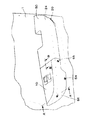
図1は、本発明における一の実施の形態を採用した自動車用のドアトリムの斜視図、図2は図1のアームレスト付近を拡大して描画した斜視図、図3は同じく分解斜視図、図4は図2のA−A断面図、図5は同じくB−B断面図である。
【0016】
図において、ドアトリム本体1には、スピーカグリル30やポケット部40が設けられているほか、アームレスト20が突設されている。
【0017】
アームレスト20の棚部24における後半部はプルハンドル部50が設置され、プルハンドル部50はその裏面に設けたクリップ(不図示)等をアームレスト20の棚部24に形成した取付けボス部51,51に取着することによりアームレスト20に装着されている。
【0018】
アームレスト20の棚部24における前半部はスイッチパネル10が設置されている。
【0019】
即ち、スイッチパネル10の前端部(または後端部)には、突片11が垂設され、突片11には位置決め嵌合部12が設けられている。
【0020】
スイッチパネル10の後端部(または前端部)には、略L字状の係合片13が、その係合爪13aが外向きになるように、形成されている。
【0021】
アームレスト20の棚部24における前端部には、スイッチパネル10を取り付けるための取付け孔21が形成されており、取付け孔21より後端側(または前端側)外端側に、突片22を突設し、突片22には、取付け用ボス部23が立設されている。
【0022】
ドアトリム本体1における取付け孔21に対し前端側(または後端側)には、位置決め嵌合部12が嵌合する位置決めボス部2が突設されており、位置決めボス部2と位置決め嵌合部12との嵌合により、アームレスト20に対してスイッチパネル10の位置決めを行っている。
【0023】
スイッチパネル10に対向するアームレスト20の側壁には、アームレストカバー60が設けられている。
【0024】
アームレストカバー60は、その裏面に3つの取付け用ボス61,62,63を立設されている。
【0025】
取付け用ボス61は管状に形成されて、位置決めボス部2とともに位置決め嵌合部12に嵌合するように形成されている。
【0026】
アームレストカバー60の略中央に存在する取付け用ボス62はドアトリム本体1に設けた取付け孔3とともに、ねじ64が螺合するようになっている。
【0027】
取付け用ボス63はアームレスト20の棚部24に設けた取付け用ボス部23に当接して、取付け用ボス部23とともにねじ65が螺合するようになっている。
【0028】
以上のように構成する場合、アームレスト20にスイッチパネル10、アームレストカバー60及びプルハンドル部50を取付けるには、先ず、プルハンドル50の裏面に設けたクリップ等を取付けボス51,51に挿着して、プルハンドル部50をアームレスト20の棚部24の後半部に取付けるとともに、スイッチパネル10の係合片13を取付け孔3をくぐらせることによって係合爪13aを棚部24の裏面に係合した状態で、位置決め嵌合部12にドアトリム本体1側の位置決めボス部2を嵌合させる。
【0029】
次に、アームレストカバー60の取付け用ボス61をスイッチパネル10の位置決め嵌合部12に嵌合して、ドアトリム本体1の位置決めボス部2に当接させるとともに、取付け用ボス62,63を取付け孔3及び取付け用ボス部23にそれぞれ対向させる。
【0030】
次に、ねじ64,65,66をそれぞれ取付け孔3、取付け用ボス部23、位置決めボス部2に螺合して、アームレストカバー60と共にスイッチパネル10をアームレスト20に取付ける。
【0031】
以上説明した本発明における実施の形態によれば、スイッチパネル10のアームレスト20への取付けは、位置決め嵌合部12に位置決めボス部2を嵌合した状態でねじ66により位置決め嵌合部12及び位置決めボス部2を共締めし、且つ、スイッチパネル10の前端側(または後端側)に係合片13を形成し、係合片13をアームレスト20の棚部24に形成した取付け孔21に係合することにより、スイッチパネル10の前端側(または後端側)を係着して行うことから、鉄クリップを使用せずにスイッチパネル10の取付けが可能になって、部品点数の軽減及び鉄クリップのアームレスト20への取位置決め嵌合部に嵌合する或いは付け作業をなくすことができる。
【0032】
また、位置決め嵌合部12に嵌合する位置決めボス部2をドアトリム本体1側に形成したことにより、アームレスト20の取付け孔21に製作誤差があったとしても、関係なくアームレスト20の正規の位置にスイッチパネル10を確実に取付けることができる。
【0033】
また、スイッチパネル10とアームレストカバー60とを同時にアームレスト20に取付けることができ、取付け工数の軽減を図ることができる。
【0034】
図6及び図7は本発明における他の実施の形態を示すもので、取付け用ボス部61の外周に複数個の嵌合突起67を形成するとともに、嵌合突起67が嵌合する凹溝14を位置決め嵌合部12に形成して、凹溝14に嵌合突起67を嵌合することにより位置決め嵌合部12に対し取付け用ボス61の回り止めを施している。
【0035】
この実施の形態によれば、嵌合突起67と凹溝14との嵌合により、ドアトリム本体1と共にアームレスト20に対するスイッチパネル10の回り止めを行うことができ、位置決め嵌合部12と取付け用ボス61とのねじ66による共締め作業を片手で簡単に行うことができる。
【0036】
【発明の効果】
以上説明したように本発明において、スイッチパネルのアームレストへの取付けは、位置決め嵌合部に位置決めボス部を嵌合した状態でねじにより位置決め嵌合部及び位置決めボス部を共締めすることにより、鉄クリップを使用せずにスイッチパネルの取付けが可能となって、部品点数の軽減及び鉄クリップのアームレストへの取位置決め嵌合部に嵌合する或いは付け作業をなくすことができる。
【0037】
また、本発明によれば、位置決め嵌合部に嵌合する位置決めボス部をドアトリム本体側に形成したことにより、スイッチパネルの取付け孔に製作誤差があったとしても、関係なくアームレストの正規の位置に確実に取付けることができる。
【図面の簡単な説明】
【図1】本発明における一の実施の形態を採用した自動車用のドアトリムの斜視図である。
【図2】図1のアームレスト周辺を拡大して描画した斜視図である。
【図3】図1におけるアームレスト付近を拡大して描画した分解図である。
【図4】図2のA−A断面図である。
【図5】図2のB−B断面図である。
【図6】本発明における他の実施の形態を示す要部分解斜視図である。
【図7】図6におけるドアトリム側位置決めボス部とスイッチパネル側位置決め嵌合部との嵌合状態を示す縦断面図である。
【図8】従来のドアトリムのアームレスト周辺を描画した分解斜視図である。
【符号の説明】
1 ドアトリム本体
2 位置決めボス部
10 スイッチパネル
12 位置決め嵌合部
13 係合片
14 凹溝
20 アームレスト
21 取付け孔
24 棚部
60 アームレストカバー
61 取付け用ボス
66 ねじ
67 嵌合突起[0001]
BACKGROUND OF THE INVENTION
The present invention relates to a switch panel mounting structure for an automotive door trim for mounting a switch panel on an armrest shelf projecting from an inner side of the automotive door trim.
[0002]
[Prior art]
Conventionally, as this type of mounting structure, one shown in FIG. 8 is known.
[0003]
According to FIG. 8, the armrest b is projected from the door trim body a, the pull handle portion c is provided in the rear half of the shelf of the armrest b, and the switch panel d is provided in the front half of the shelf.
[0004]
The switch panel d is formed by engaging an L-shaped engagement piece f provided at the front end portion of the switch panel and an iron clip g provided at the rear end portion in the mounting hole e provided in the shelf portion of the armrest b. It is attached to the armrest b.
[0005]
[Problems to be solved by the invention]
In the conventional structure configured as described above, the switch panel b is mounted by engaging the engaging piece f and the iron clip g with the mounting hole e. The iron clip g is required and the number of parts is large, and the man-hour for attaching the iron clip g to the switch panel b is also required.
[0006]
In addition, there may be a manufacturing error in the size of the mounting hole e, and the engagement margin of the engaging piece f or the iron clip g may be reduced, so that the ball mounting for securely mounting the switch panel to the armrest is possible. Work may be required for a long time.
[0007]
SUMMARY OF THE INVENTION In view of the above, the present invention provides a switch panel mounting structure for an automotive door trim that does not use an iron clip and can securely mount the switch panel to the armrest even if there is a manufacturing error in the mounting hole. The purpose is that.
[0008]
[Means for Solving the Problems]
To achieve the above object, according to the present invention, there is provided a switch panel mounting structure for an automotive door trim in which a switch panel is installed on a shelf portion of an armrest protruding from a door trim main body. A positioning fitting portion is formed on one side, a positioning boss portion to which the positioning fitting portion is fitted is formed on the door trim body , an armrest cover is provided on the side wall of the armrest , and the positioning boss on the door trim body side is provided on the armrest cover. parts together forming a mounting boss that fits into the positioning fitting portion, and a positioning boss and the positioning fitting portion in a state of fitting the positioning boss portion and the mounting boss in the positioning fitting portion and the mounting boss It is configured by tightening together.
[0009]
According to the present invention, the mounting of the switch panel to the armrest is performed by tightening the positioning fitting portion and the positioning boss portion with screws in a state where the positioning boss portion is fitted to the positioning fitting portion. The switch panel can be mounted without using the, so that the number of parts can be reduced, and the fitting operation or fitting operation of the iron clip to the armrest can be eliminated.
[0010]
Further, according to the present invention, since the positioning boss portion to be fitted to the positioning fitting portion is formed on the door trim main body side, even if there is a manufacturing error in the mounting hole of the armrest, it is in the normal position of the armrest regardless of the manufacturing error. Can be installed reliably.
[0011]
Further , according to the present invention , the switch panel and the armrest cover can be attached to the armrest at the same time, and the number of attachment steps can be reduced .
[0012]
Further, the present invention is to form a fitting projection on the outer periphery of the mounting boss portion, to form a concave groove fitting projection is fitted into the positioning fitting portion, the fitting in the groove and relative positioning fitting portion by fitting the projection constitutes subjected to detent of the mounting boss portion.
[0013]
According to the present invention, the armrest cover can be prevented from rotating with respect to the switch panel by fitting the fitting protrusion and the concave groove, and the joint fastening operation with the screw between the positioning fitting portion and the mounting boss portion can be performed with one hand. Easy to do.
[0014]
DETAILED DESCRIPTION OF THE INVENTION
Hereinafter, embodiments of the present invention will be described with reference to the drawings.
[0015]
1 is a perspective view of a door trim for an automobile adopting one embodiment of the present invention, FIG. 2 is an enlarged perspective view of the vicinity of the armrest in FIG. 1, FIG. 3 is an exploded perspective view, and FIG. Is a cross-sectional view taken along the line AA in FIG. 2, and FIG. 5 is a cross-sectional view taken along the line BB.
[0016]
In the figure, the door trim
[0017]
A
[0018]
The
[0019]
That is, the projecting
[0020]
A substantially L-
[0021]
A
[0022]
On the front end side (or rear end side) of the
[0023]
An
[0024]
The
[0025]
The mounting
[0026]
A mounting
[0027]
The mounting
[0028]
In the case of the above configuration, in order to attach the
[0029]
Next, the mounting
[0030]
Next, the
[0031]
According to the embodiment of the present invention described above, the
[0032]
Further, since the
[0033]
Moreover, the
[0034]
6 and 7 show another embodiment of the present invention, in which a plurality of
[0035]
According to this embodiment, the
[0036]
【The invention's effect】
As described above, in the present invention, the mounting of the switch panel to the armrest is performed by tightening the positioning fitting portion and the positioning boss portion with screws in a state in which the positioning boss portion is fitted to the positioning fitting portion. The switch panel can be mounted without using a clip, so that the number of parts can be reduced, and the fitting / attaching operation to the positioning / fitting portion of the iron clip to the armrest can be eliminated.
[0037]
In addition, according to the present invention, since the positioning boss portion that fits into the positioning fitting portion is formed on the door trim body side, even if there is a manufacturing error in the mounting hole of the switch panel, the normal position of the armrest is irrelevant. Can be securely installed.
[Brief description of the drawings]
FIG. 1 is a perspective view of a door trim for an automobile adopting an embodiment of the present invention.
2 is an enlarged perspective view of the periphery of the armrest of FIG. 1. FIG.
FIG. 3 is an exploded view in which the vicinity of the armrest in FIG. 1 is enlarged and drawn.
4 is a cross-sectional view taken along the line AA in FIG.
5 is a cross-sectional view taken along the line BB in FIG.
FIG. 6 is an exploded perspective view showing a main part of another embodiment of the present invention.
7 is a longitudinal sectional view showing a fitting state between the door trim side positioning boss portion and the switch panel side positioning fitting portion in FIG. 6;
FIG. 8 is an exploded perspective view depicting the vicinity of an armrest of a conventional door trim.
[Explanation of symbols]
DESCRIPTION OF
Claims (2)
前記スイッチパネルの前端側及び後端側のいずれか一方に位置決め嵌合部を形成するとともに、該位置決め嵌合部が嵌合する位置決めボス部を前記ドアトリム本体に形成し、
且つ、前記アームレストの側壁にアームレストカバーを設け、該アームレストカバーに前記ドアトリム本体側の前記位置決めボス部とともに前記位置決め嵌合部に嵌合する取付けボスを形成し、
前記位置決め嵌合部に前記位置決めボス部及び前記取付け用ボス部を嵌合した状態で前記位置決め嵌合部と前記位置決めボス部及び取付け用ボス部とを共締めしたことを特徴とする自動車用ドアトリムのスイッチパネル取付け構造。In the switch panel mounting structure of an automotive door trim that installs a switch panel on the armrest shelf protruding from the door trim body,
Forming a positioning fitting portion on either the front end side or the rear end side of the switch panel, and forming a positioning boss portion to which the positioning fitting portion fits in the door trim body;
And an armrest cover is provided on the side wall of the armrest, and an attachment boss that fits the positioning fitting portion together with the positioning boss portion on the door trim main body side is formed on the armrest cover,
Automotive, characterized in that the fastened together and the previous SL positioning fitting portions the positioning boss and the mounting boss portion in a state of fitting the said positioning boss and said mounting boss in the positioning fitting portion Door trim switch panel mounting structure.
Priority Applications (1)
| Application Number | Priority Date | Filing Date | Title |
|---|---|---|---|
| JP2000078403A JP3723034B2 (en) | 2000-03-21 | 2000-03-21 | Switch panel mounting structure for automotive door trim |
Applications Claiming Priority (1)
| Application Number | Priority Date | Filing Date | Title |
|---|---|---|---|
| JP2000078403A JP3723034B2 (en) | 2000-03-21 | 2000-03-21 | Switch panel mounting structure for automotive door trim |
Publications (2)
| Publication Number | Publication Date |
|---|---|
| JP2001262935A JP2001262935A (en) | 2001-09-26 |
| JP3723034B2 true JP3723034B2 (en) | 2005-12-07 |
Family
ID=18595819
Family Applications (1)
| Application Number | Title | Priority Date | Filing Date |
|---|---|---|---|
| JP2000078403A Expired - Fee Related JP3723034B2 (en) | 2000-03-21 | 2000-03-21 | Switch panel mounting structure for automotive door trim |
Country Status (1)
| Country | Link |
|---|---|
| JP (1) | JP3723034B2 (en) |
Cited By (1)
| Publication number | Priority date | Publication date | Assignee | Title |
|---|---|---|---|---|
| CN103151193A (en) * | 2013-01-30 | 2013-06-12 | 黄荣生 | Novel switch panel shift fork type mounting structure |
Families Citing this family (6)
| Publication number | Priority date | Publication date | Assignee | Title |
|---|---|---|---|---|
| JP3780275B2 (en) * | 2003-10-09 | 2006-05-31 | 本田技研工業株式会社 | Automatic switchgear for vehicles |
| JP4933087B2 (en) * | 2005-11-29 | 2012-05-16 | テイ・エス テック株式会社 | Vehicle interior material and method for assembling the vehicle interior material |
| JP4935512B2 (en) * | 2007-06-06 | 2012-05-23 | マツダ株式会社 | Slide door prevention structure |
| JP5892379B2 (en) * | 2012-06-21 | 2016-03-23 | トヨタ紡織株式会社 | Vehicle door trim |
| US11186237B2 (en) | 2018-11-21 | 2021-11-30 | Kasai Kogyo Co., Ltd. | Door armrest |
| CN113071314B (en) * | 2021-05-10 | 2022-07-15 | 广州鑫欣塑胶制品有限公司 | Automobile back door switch panel |
-
2000
- 2000-03-21 JP JP2000078403A patent/JP3723034B2/en not_active Expired - Fee Related
Cited By (1)
| Publication number | Priority date | Publication date | Assignee | Title |
|---|---|---|---|---|
| CN103151193A (en) * | 2013-01-30 | 2013-06-12 | 黄荣生 | Novel switch panel shift fork type mounting structure |
Also Published As
| Publication number | Publication date |
|---|---|
| JP2001262935A (en) | 2001-09-26 |
Similar Documents
| Publication | Publication Date | Title |
|---|---|---|
| JP3723034B2 (en) | Switch panel mounting structure for automotive door trim | |
| JP3908500B2 (en) | Room lamp fixing structure | |
| JP3367842B2 (en) | Mounting structure of heater control device | |
| JP2535329Y2 (en) | Power window switch bezel mounting structure | |
| JPH0629134Y2 (en) | Radiator grill mounting structure | |
| JP4020371B2 (en) | Modular structure in roof trim | |
| JP3014587B2 (en) | Mounting structure of switch panel to instrument panel | |
| JP3631055B2 (en) | Power window finisher mounting structure for door armrests for automobiles | |
| JP2000071885A (en) | Vehicular console box | |
| JPS5848166Y2 (en) | Mounting structure for automotive decorative parts | |
| JPH067977Y2 (en) | Car lamp mounting structure | |
| JP3542006B2 (en) | Bumper mounting structure | |
| JPH0569784A (en) | Radiator grille | |
| JP3698475B2 (en) | Meter hood mounting structure | |
| JP4005450B2 (en) | Mounting structure of switch device | |
| JP3812786B2 (en) | Mounting structure for automobile dash side trim | |
| JP2537093Y2 (en) | Fixed structure of two articles | |
| JPH043885Y2 (en) | ||
| JP4497500B2 (en) | Inner remote handle structure | |
| JPH10119824A (en) | Mounting structure for hood insulator | |
| JP3989708B2 (en) | Trim member mounting structure | |
| JPH0711651Y2 (en) | Vehicle seat armrest mounting structure | |
| JP2001180331A (en) | Instrument panel structure | |
| JPH08156720A (en) | Grille attaching structure | |
| JPH11291945A (en) | Mounting structure of rear parcel |
Legal Events
| Date | Code | Title | Description |
|---|---|---|---|
| A977 | Report on retrieval |
Free format text: JAPANESE INTERMEDIATE CODE: A971007 Effective date: 20050527 |
|
| A131 | Notification of reasons for refusal |
Free format text: JAPANESE INTERMEDIATE CODE: A131 Effective date: 20050531 |
|
| A521 | Written amendment |
Free format text: JAPANESE INTERMEDIATE CODE: A523 Effective date: 20050720 |
|
| TRDD | Decision of grant or rejection written | ||
| A01 | Written decision to grant a patent or to grant a registration (utility model) |
Free format text: JAPANESE INTERMEDIATE CODE: A01 Effective date: 20050913 |
|
| A61 | First payment of annual fees (during grant procedure) |
Free format text: JAPANESE INTERMEDIATE CODE: A61 Effective date: 20050914 |
|
| R150 | Certificate of patent or registration of utility model |
Free format text: JAPANESE INTERMEDIATE CODE: R150 |
|
| LAPS | Cancellation because of no payment of annual fees |