JP3722710B2 - Map display device and navigation device - Google Patents
Map display device and navigation device Download PDFInfo
- Publication number
- JP3722710B2 JP3722710B2 JP2001076752A JP2001076752A JP3722710B2 JP 3722710 B2 JP3722710 B2 JP 3722710B2 JP 2001076752 A JP2001076752 A JP 2001076752A JP 2001076752 A JP2001076752 A JP 2001076752A JP 3722710 B2 JP3722710 B2 JP 3722710B2
- Authority
- JP
- Japan
- Prior art keywords
- information
- map
- unit
- map data
- dimensional
- Prior art date
- Legal status (The legal status is an assumption and is not a legal conclusion. Google has not performed a legal analysis and makes no representation as to the accuracy of the status listed.)
- Expired - Fee Related
Links
Images


Description
【0001】
【発明の属する技術分野】
本発明は、地図表示装置およびナビゲーション装置に関し、より特定的には、通信部を介して外部から入力されてくる通過しようとする料金所を特定するための情報を含む通信情報を解析し、地図内のオブジェクトに変換して合成表示するとともに、所定の場合には課金処理のための通信を行う地図表示装置およびナビゲーション装置に関する。
【0002】
【従来の技術】
従来の地図表示装置およびナビゲーション装置は、既存の情報通信システムからの交通情報や道路規制情報、あるいはインターネットから流れてくる情報等を地図表示画面とは別の画面に表示する。すなわち、従来の地図表示装置およびナビゲーション装置は、これらの情報を地図内のオブジェクトに変換して合成表示するわけではない。
【0003】
ここで、既存の情報通信システムとしては、VICS(Vehicle Information and Communication System)と呼ばれる、道路の渋滞情報や事故情報などの道路情報を、FM多重放送、電波ビーコンおよび光ビーコン等を利用してリアルタイムで発信する情報通信システムが存在する。
【0004】
このような既存の情報通信システムにおいて送信される渋滞情報は、具体的には渋滞している道路のリンク番号などが含まれる。したがって、従来のナビゲーション装置は、一般的にはこのような渋滞情報を、模式的に表された簡略な地図上に表現して、ナビゲーション用の地図画面とは別の画面に表示する。
【0005】
また、渋滞情報を同一画面上に表示する場合であっても、従来のナビゲーション装置は、渋滞情報を地図内のオブジェクトに変換して合成表示するわけではなく、送信されてきた道路のリンク番号に対応する道路の色のみを変更して表示するにすぎない。このように従来のナビゲーション装置が色のみを変更して表示するのは、既存のシステムにおいて生成されるオブジェクトが固定されているからである。したがって、従来のナビゲーション装置が新しいオブジェクトを生成することなく渋滞情報を表示するためには、色を変更する方法しか存在しない。
【0006】
また、最近のナビゲーション装置には、インターネットブラウザが追加されて、地図画面とは別の画面にインターネットからの情報を表示するものも存在する。このような装置は、外部の情報から隔絶した車や人を、内蔵された通信系によって、インターネットを介して外部と接続することになる。
【0007】
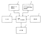
以上のような従来の地図表示装置およびナビゲーション装置の構成および動作について、図46および図47を用いながら説明する。図46は、従来の地図表示装置の構成を示すブロック図である。図46において、従来の地図表示装置は、入力部2と、地図データ格納部3と、地図データ作成部400と、表示器5と、通信部7とを備える。
【0008】
入力部2は、本地図表示装置における機能選択や地点設定等を行うために用いられる。この入力部2から出力される指示情報は、地図データ作成部400へ入力される。
【0009】
地図データ格納部3は、地形、交差点や道路の接続状況やその座標・形状・属性・規制情報などの2次元地図データあるいは3次元地図データが格納されている。この地図データ格納部3に格納された地図データは、地図データ作成部400によって適宜読み出されて利用される。
【0010】
通信部7は、外部に設けられた通信システムとの情報の送受信を行う。外部システムとの送受信には、例えば、電話回線やDAB(Digital Audio Broadcast)、地上波ディジタル放送などが用いられる。通信部7から得られた各種情報は、そのまま加工されることなく、表示器5へ入力される。
【0011】
地図データ作成部400は、地図データ格納部3に格納されている地図データに基づいて、地図を作成する。表示器5は、地図データ作成部400において作成された地図を表示する。また、表示器5は、当該地図とは別の画面において、インターネットやVICS等から得られた情報を表示する。典型的には、表示器5は、インターネットブラウザやVICS専用画面上に得られた情報を表示する。
【0012】
次に、図47は、上記のような従来のナビゲーション装置の構成を示すブロック図である。なお、ここでは、本ナビゲーション装置は、車両に搭載されているものとする。図47において、従来のナビゲーション装置は、入力部2と、位置検出部9と、地図データ格納部3と、経路選出部100と、誘導部110と、通信部7と、表示器5とを備える。
【0013】
入力部2は、ユーザによって操作され、機能選択(処理項目変更、地図切り替え、階層変更等)や、地点設定等を行うために用いられる。この入力部2から出力される指示情報は、経路選出部100に入力される。位置検出部9は、車両の現在位置を検出する。そして、位置検出部9から出力される車両の現在位置情報は、経路選出部100および誘導部110へ入力される。
【0014】
地図データ格納部3は、地形、交差点や道路の接続状況や座標・形状・属性・規制情報などの2次元地図データあるいは3次元地図データを格納する。この地図データ格納部3に格納された地図データは、経路選出部100および誘導部110によって適宜読み出されて利用される。
【0015】
通信部7は、インターネットなどの外部システムから、各種情報の送受信を行う。外部システムとの送受信には、例えば、電話回線やDAB、地上波ディジタル放送などが用いられる。通信部7から得られた各種情報は、そのまま加工されることなく、表示器5へ入力される。
【0016】
経路選出部100は、入力部2から入力された指示情報の指示に従って、必要となる範囲の地図データを地図データ格納部3から読み込む。そして、経路選出部100は、入力部2から入力された地点情報等の指示情報と、位置検出部9から入力された車両の現在位置情報とに基づいて、出発地や目的地を決定し、出発地から目的地間の最小コスト経路を探索する。経路選出部100から出力された経路情報は、誘導部110へ入力される。
【0017】
誘導部110は、経路選出部100から入力された経路情報と、位置検出部9から入力された車両の位置情報と、地図データ格納部3から入力された地図データとに基づき、2次元または3次元景観の地図画面を生成する。生成された2次元または3次元の地図画面は、表示器5へ入力される。
【0018】
表示器5は、誘導部110によって生成された地図画面を表示する。また、表示器5は、地図画面とは別の画面において、インターネットやVICS等から得られた情報を表示する。典型的には、表示器5は、インターネットブラウザやVICS専用画面上に得られた情報を表示する。
【0019】
このような地図表示装置およびナビゲーション装置によれば、ユーザは外部から最新の情報、例えば、交通情報や駐車場の情報などを容易に入手することができる。したがって、このような従来の地図表示装置ないしナビゲーション装置は、ユーザーに対して目的地の各種情報をできるだけ正確に把握させることができる。
【0020】
【発明が解決しようとする課題】
しかし、従来のナビゲーション装置において、基本的にインターネットブラウザは、地図画面とは別の画面に表示される。また、VICSによる渋滞情報も同様に、別画面の簡略な地図上に表示されるのが一般的である。したがって、必要な情報と表示されている情報とを比較参照し、関連づけることは、ユーザーが視線を動かして行わなければならない。しかし、このような関連付けをユーザーが行う場合には、一旦車両を停止させることが好ましい。したがって、上述のようなナビゲーション装置の利点は、車両が走行中には充分に発揮できないという問題点がある。このことは、本ナビゲーション装置が車両以外の移動体に搭載されるものであっても、歩行者が携帯するものであっても変わりがない。
【0021】
しかし、従来のナビゲーション装置において、ナビゲーション画面上に新しいオブジェクトを生成することなく各種情報を合成表示することは、前述のように道路等の表示色を変更して表示する場合を除けば、極めて困難である。
【0022】
また、ここで、地図表示装置およびナビゲーション装置が内蔵された通信手段を介して新しいオブジェクトを生成するために必要な画像や三次元ポリゴンデータを含む全てのデータを受信して、地図画面上に合成表示するような構成も考えられる。しかし、このような地図表示装置およびナビゲーション装置の構成によれば、送受信する情報量が多くなって、経済的ではない。
【0023】
他方、地図表示装置およびナビゲーション装置が、各種情報に対応するあらゆるオブジェクトを生成するためのデータを予め保持するような構成も考えられる。しかし、このような地図表示装置およびナビゲーション装置の構成によれば、オブジェクトを記憶するために設けられる記憶媒体の容量が非常に大きくなって、やはり経済的ではないという問題点がある。
【0024】
それ故に、本発明の目的は、リアルタイムに変化する規制情報や渋滞情報、あるいはインターネットから流れてくる各種情報や通過しようとする料金所を特定するための情報を含む通信情報を地図上に合成して表示し、ユーザが視線を動かさず、より直感的に情報を把握することができるとともに、所定の場合には課金処理のための通信を行う地図表示装置およびナビゲーション装置を提供することである。
【0025】
また、本発明の他の目的は、送受信する情報量が僅少でありながら、オブジェクトを記憶するための記憶媒体の容量を小さくすることができる上記の地図表示装置およびナビゲーション装置を提供することである。
【0026】
【課題を解決するための手段および発明の効果】
第1の発明は、装置外部から送信されてきた通信情報を所定の形状を有するオブジェクトとして地図上に合成表示するとともに、所定の場合には課金処理のための通信を行う地図表示装置であって、
ユーザからの指示が入力される入力部と、
地図情報を予め格納する地図データ格納部と、
オブジェクトを地図上に提示するためのオブジェクトモデル提示情報を格納するオブジェクトモデル提示情報格納部と、
通過しようとする料金所を特定するための情報を含む通信情報を受信するとともに、所定の場合には課金処理のための課金情報を送信する通信部と、
通信情報およびオブジェクトモデル提示情報格納部から入力された対応するオブジェクトモデル提示情報を解釈してオブジェクトを生成し、地図上に合成するとともに、所定の場合には課金情報を生成する地図データ合成部と、
地図データ合成部によって合成された地図画面をユーザに対して表示する表示部とを備える。
【0027】
上記のように、第1の発明によれば、地図データ格納部に格納してある地図データと通信部から送られてくる情報とオブジェクトモデル提示情報格納部に格納してある情報に基づいてオブジェクトを地図データ空間内に合成して提示でき、さらに課金処理を行うことができるので、リアルタイムに変化する規制情報や渋滞情報、あるいはインターネットから流れてくる各種情報を、視線を動かさず、より直感的に表現することで、ユーザの視認性の向上を図ることができるとともに、自動料金徴収システムの端末として動作してユーザの利便を図ることができる。
【0028】
さらに、予め記憶媒体の中に登録されているのはリアルタイムに提示条件や提示内容の変更を行いたいオブジェクトモデル提示情報であり、実行時に条件が整えばその場でオブジェクトを作成削除を行うことができる。したがって、記憶する容量が少ないだけでなく、通信部を介してオブジェクトモデル提示条件の更新や追加削除を行う場合も、記憶する容量を少なくすることができる。そのために、経済的な地図表示装置を提供することができる。
【0029】
第2の発明は、第1の発明に従属する発明であって、
オブジェクトモデル提示情報は、
オブジェクトが有する形状に関する情報と、
オブジェクトにおける時空間の振る舞いに関する情報とを含む。
【0030】
上記のように、第2の発明によれば、オブジェクトモデル提示情報格納部に格納される情報をオブジェクトの形状に関する情報と時空間の振る舞いに関する情報との組によって構成するので、新しいオブジェクトモデル提示情報と入れ替える場合や、形状情報あるいは時空間の振る舞いに関する情報の一部だけを入れ替える場合のような情報の管理を簡単に行うことができる。
【0031】
第3の発明は、第2の発明に従属する発明であって、
オブジェクトにおける時空間の振る舞いに関する情報は、コンパイルなしに実行することができるオブジェクト指向のインタープリタ言語を用いて記述されることを特徴とする。
【0032】
上記のように、第3の発明によれば、オブジェクトモデル提示情報格納部に格納される情報をコンパイルなしで実行可能なスクリプトで記述できるので、地図表示装置に依存しないオブジェクトモデル提示情報を利用することができる。したがって、オブジェクトモデル提示情報を提供するサーバー側の運用を容易にすることができる。また、例えばJAVAのように標準的なスクリプト言語を使用することによって、広くネットワークを介してオブジェクトモデル提示情報を取り込むことができるので、オブジェクトモデル提示情報の流通と再利用性を向上させることができる。
【0033】
第4の発明は、第2の発明に従属する発明であって、
オブジェクトにおける時空間の振る舞いに関する情報は、実行条件と、実行関数とを含む。
【0034】
上記のように、第4の発明によれば、実行条件を固定的にする必要がない。したがって、オブジェクトがユーザの入力や通信部から入力された情報に対して、毎回同じ反応をする必要がなく、意外性と融通性のある提示内容を提供することができる。
【0035】
第5の発明は、第1の発明に従属する発明であって、
地図データ合成部は、
通信情報およびオブジェクトモデル提示情報格納部から入力された対応するオブジェクトモデル提示情報を解釈して実行するオブジェクト提示情報実行部と、
オブジェクト提示情報実行部における実行結果が入力されてオブジェクトを生成するオブジェクト作成部と、
オブジェクトを地図上に合成するデータ合成部とを含む。
【0036】
上記のように、第5の発明によれば、2次元ないし3次元のオブジェクトを生成して、2次元ないし3次元の地図上に合成することができるので、各種情報を、視線を動かさず、より直感的に表現することで、ユーザの視認性の向上を図ることができる。
【0037】
第6の発明は、第5の発明に従属する発明であって、
地図データ合成部は、地図データ格納部から入力された2次元データの地図情報に基づいて3次元の地図を作成する三次元地図作成部をさらに含み、
データ合成部は、オブジェクトを三次元地図作成部が作成した地図上に合成することを特徴とする。
【0038】
上記のように、第6の発明によれば、2次元ないし3次元のオブジェクトを生成して、3次元の地図上に合成することができるので、各種情報を、視線を動かさず、より直感的に表現することで、ユーザの視認性の向上を図ることができる。また、2次元データの地図情報に基づいて3次元の地図を作成するので、地図データ格納部において地図を記憶するための記憶媒体の容量を小さくすることができる。
【0039】
第7の発明は、第5の発明に従属する発明であって、
地図データ合成部は、オブジェクト作成部が生成した2次元のオブジェクトを3次元のオブジェクトへ変換する二次元/三次元座標変換部をさらに含み、
データ合成部は、二次元/三次元座標変換部によって変換された3次元のオブジェクトを地図上に合成することを特徴とする。
【0040】
上記のように、第7の発明によれば、2次元のオブジェクトを生成して、2次元または3次元の地図上に合成することができるので、各種情報を、視線を動かさず、より直感的に表現することで、ユーザの視認性の向上を図ることができる。また、2次元データのオブジェクトモデル提示情報に基づいて3次元のオブジェクトを作成するので、オブジェクトモデル提示情報格納部においてオブジェクトモデル提示情報を記憶するための記憶媒体の容量を小さくすることができる。
【0041】
第8の発明は、第1の発明に従属する発明であって、
地図データ合成部は、所定の有料区間における入り口と出口とに設けられた料金所に関する通信情報を参照して課金情報を生成し、有料区間における料金額を含むオブジェクトを生成して地図上に合成することを特徴とする。
【0042】
第9の発明は、第1の発明に従属する発明であって、
有料区間における料金支払いに用いられる通行券に対応する通行券情報を格納する通行券情報格納部をさらに備え、
地図データ合成部は、通行券を購入する場合には通行券情報格納部に格納された通行券情報を作成し、所定の場合には通行券情報を変更することを特徴とする。
【0043】
第10の発明は、第9の発明に従属する発明であって、
通行券情報は、通行券の有効期限に関する情報を含み、
地図データ合成部は、通行券の有効期限に関する情報を参照し、所定の場合に警告メッセージを作成して、表示部に表示させることを特徴とする。
【0044】
上記のように、第8ないし第10の発明によれば、本地図表示装置は、自動料金徴収システムの端末として動作してユーザの利便を図ると共に、料金等の各種情報を、直感的に表現することで、ユーザの視認性を向上することができる。
【0045】
第11の発明は、装置外部から送信されてきた通信情報を所定の形状を有するオブジェクトとして地図上に合成表示し、目的地までの誘導案内を行うとともに、所定の場合には課金処理のための通信を行うナビゲーション装置であって、
ユーザからの指示が入力される入力部と、
現在位置を検出する位置検出部と、
地図情報を予め格納する地図データ格納部と、
オブジェクトを地図上に提示するためのオブジェクトモデル提示情報を予め格納するオブジェクトモデル提示情報格納部と、
入力部から入力された指示と、位置検出部が検出した現在位置と、地図データ格納部に格納された地図情報とに基づいて、目的地までの経路を選出する経路選出部と、
通過しようとする料金所を特定するための情報を含む通信情報を受信するとともに、所定の場合には課金処理のための課金情報を送信する通信部と
通信情報およびオブジェクトモデル提示情報格納部から入力された対応するオブジェクトモデル提示情報を解釈してオブジェクトを生成し、地図上に合成する地図データ合成部と、
通信部によって受信された通信情報と、経路選出部によって選出された経路と、位置検出部によって検出された現在位置と、地図データ格納部からの地図情報とが入力されて、目的地までの誘導案内を生成すると共に、地図データ合成部によって合成された地図画面を出力し、所定の場合には課金情報を生成する誘導部と、
誘導部から入力された地図画面をユーザに対して表示する表示部とを備える。
【0046】
第12の発明は、第11の発明に従属する発明であって、
オブジェクトモデル提示情報は、
オブジェクトが有する形状に関する情報と、
オブジェクトにおける時空間の振る舞いに関する情報とを含む。
【0047】
第13の発明は、第12の発明に従属する発明であって、
オブジェクトにおける時空間の振る舞いに関する情報は、コンパイルなしに実行することができるオブジェクト指向のインタープリタ言語を用いて記述されることを特徴とする。
【0048】
第14の発明は、第12の発明に従属する発明であって、
オブジェクトにおける時空間の振る舞いに関する情報は、実行条件と、実行関数とを含む。
【0049】
第15の発明は、第11の発明に従属する発明であって、
地図データ合成部は、
通信情報およびオブジェクトモデル提示情報格納部から入力された対応するオブジェクトモデル提示情報を解釈して実行するオブジェクト提示情報実行部と、
オブジェクト提示情報実行部における実行結果が入力されてオブジェクトを生成するオブジェクト作成部と、
オブジェクトを地図上に合成するデータ合成部とを含む。
【0050】
第16の発明は、第15の発明に従属する発明であって、
地図データ合成部は、地図データ格納部から入力された2次元データの地図情報に基づいて3次元の地図を作成する三次元地図作成部をさらに含み、
データ合成部は、オブジェクトを三次元地図作成部が作成した地図上に合成することを特徴とする。
【0051】
第17の発明は、第15の発明に従属する発明であって、
地図データ合成部は、オブジェクト作成部が生成した2次元のオブジェクトを3次元のオブジェクトへ変換する二次元/三次元座標変換部をさらに含み、
データ合成部は、二次元/三次元座標変換部によって変換された3次元のオブジェクトを地図上に合成することを特徴とする。
【0052】
第18の発明は、第11の発明に従属する発明であって、
誘導部は、所定の有料区間における入り口と出口とに設けられた料金所に関する通信情報を参照して課金情報を生成し、
地図データ合成部は、有料区間における料金額を含むオブジェクトを生成して地図上に合成することを特徴とする。
【0053】
第19の発明は、第11の発明に従属する発明であって、
所定の有料区間における料金支払いに用いられる通行券に対応する通行券情報を格納する通行券情報格納部をさらに備え、
誘導部は、通行券を購入する場合には通行券情報格納部に格納された通行券情報を作成し、所定の場合には通行券情報を変更することを特徴とする。
【0054】
第20の発明は、第19の発明に従属する発明であって、
通行券情報は、通行券の有効期限に関する情報を含み、
地図データ合成部は、通行券の有効期限に関する情報を参照し、所定の場合に警告メッセージを作成して、表示部に表示させることを特徴とする。
【0055】
上記のように、第11および第20の発明によれば、前述した第1ないし第10の発明に係る地図表示装置と同様の効果を有するナビゲーション装置を提供することができる。
【0056】
第21の発明は、外部から送信されてきた通信情報を所定の形状を有するオブジェクトとして地図上に合成表示するとともに、所定の場合には課金処理のための通信を行う地図表示方法であって、
ユーザからの指示が入力される入力ステップと、
通過しようとする料金所を特定するための情報を含む通信情報を受信するとともに、所定の場合には課金処理のための課金情報を送信する通信ステップと、
通信情報および対応するオブジェクトを地図上に提示するためのオブジェクトモデル提示情報を解釈してオブジェクトを生成し、地図上に合成するとともに、所定の場合には課金情報を生成する地図データ合成ステップと、
地図データ合成ステップにおいて合成された地図画面をユーザに対して表示する表示ステップとを備える。
【0057】
第22の発明は、第21の発明に従属する発明であって、
地図データ合成ステップは、
通信情報および対応するオブジェクトモデル提示情報を解釈して実行するオブジェクト提示情報実行ステップと、
オブジェクト提示情報実行ステップにおける実行結果からオブジェクトを生成するオブジェクト作成ステップと、
オブジェクトを地図上に合成するデータ合成ステップとを含む。
【0058】
第23の発明は、第22の発明に従属する発明であって、
地図データ合成ステップは、2次元データの地図情報に基づいて3次元の地図を作成する三次元地図作成ステップをさらに含み、
データ合成ステップは、三次元地図作成ステップにおいて作成された地図上にオブジェクトを合成することを特徴とする。
【0059】
第24の発明は、第22の発明に従属する発明であって、
地図データ合成ステップは、オブジェクト作成ステップにおいて作成された2次元のオブジェクトを3次元のオブジェクトへ変換する二次元/三次元座標変換ステップをさらに含み、
データ合成ステップは、二次元/三次元座標変換ステップにおいて変換された3次元のオブジェクトを地図上に合成することを特徴とする。
【0060】
第25の発明は、外部から送信されてきた通信情報を所定の形状を有するオブジェクトとして地図上に合成表示するとともに、所定の場合には課金処理のための通信を行うナビゲーション方法であって、
ユーザからの指示が入力される入力ステップと、
通過しようとする料金所を特定するための情報を含む通信情報を受信するとともに、所定の場合には課金処理のための課金情報を送信する通信ステップと、
現在位置を検出する位置検出ステップと、
通信情報および対応するオブジェクトを地図上に提示するためのオブジェクトモデル提示情報を解釈してオブジェクトを生成し、地図上に合成する地図データ合成ステップと、
入力ステップにおいて入力された指示と、位置検出ステップにおいて検出された現在位置と、地図情報とに基づいて、目的地までの経路を選出する経路選出ステップと、
通信ステップにおいて受信された通信情報と、経路選出ステップにおいて選出された経路と、位置検出ステップにおいて検出された現在位置と、地図情報とに基づいて、目的地までの誘導案内を生成すると共に、地図データ合成ステップにおいて合成された地図画面を出力し、所定の場合には課金情報を生成する誘導ステップと、
誘導ステップにおいて出力された地図画面をユーザに対して表示する表示ステップとを備える。
【0061】
第26の発明は、外部から送信されてきた通信情報を所定の形状を有するオブジェクトとして地図上に合成表示するとともに、所定の場合には課金処理のための通信を行う地図表示装置に、
通過しようとする料金所を特定するための情報を含む通信情報およびオブジェクトを地図上に提示するためのオブジェクトモデル提示情報を解釈して実行するオブジェクト提示情報実行ステップと、
オブジェクト提示情報実行ステップにおける実行結果からオブジェクトを生成するオブジェクト作成ステップと、
オブジェクトを地図上に合成するデータ合成ステップと、
所定の場合には課金処理のための課金情報を作成する課金処理情報作成ステップとを実行させるためのプログラムを記録したコンピュータ読み取り可能な記録媒体である。
【0062】
第27の発明は、外部から送信されてきた通信情報を所定の形状を有するオブジェクトとして地図上に合成表示するとともに、所定の場合には課金処理のための通信を行うナビゲーション装置に、
通過しようとする料金所を特定するための情報を含む通信情報および対応するオブジェクトを地図上に提示するためのオブジェクトモデル提示情報を解釈してオブジェクトを生成し、地図上に合成する地図データ合成ステップと、
ユーザから入力された指示と、現在位置と、地図情報とに基づいて、目的地までの経路を選出する経路選出ステップと、
通信情報と、経路選出ステップにおいて選出された経路と、現在位置と、地図情報とに基づいて、目的地までの誘導案内を生成すると共に、地図データ合成ステップにおいて合成された地図画面を出力し、所定の場合には課金処理のための課金情報を生成する誘導ステップとを実行させるためのプログラムを記録したコンピュータ読み取り可能な記録媒体である。
【0063】
第28の発明は、外部から送信されてきた通信情報を所定の形状を有するオブジェクトとして地図上に合成表示するとともに、所定の場合には課金処理のための通信を行う地図表示装置に、
通信情報およびオブジェクトを地図上に提示するためのオブジェクトモデル提示情報を解釈して実行するオブジェクト提示情報実行ステップと、
オブジェクト提示情報実行ステップにおける実行結果からオブジェクトを生成するオブジェクト作成ステップと、
オブジェクトを地図上に合成するデータ合成ステップと、
所定の場合には課金処理のための課金情報を作成する課金処理情報作成ステップとを実行させるためのコンピュータプログラムである。
【0064】
第29の発明は、外部から送信されてきた通信情報を所定の形状を有するオブジェクトとして地図上に合成表示するとともに、所定の場合には課金処理のための通信を行うナビゲーション装置に、
通過しようとする料金所を特定するための情報を含む通信情報および対応するオブジェクトを地図上に提示するためのオブジェクトモデル提示情報を解釈してオブジェクトを生成し、地図上に合成する地図データ合成ステップと、
ユーザから入力された指示と、現在位置と、地図情報とに基づいて、目的地までの経路を選出する経路選出ステップと、
通信情報と、経路選出ステップにおいて選出された経路と、現在位置と、地図情報とに基づいて、目的地までの誘導案内を生成すると共に、地図データ合成ステップにおいて合成された地図画面を出力し、所定の場合には課金処理のための課金情報を生成する誘導ステップとを実行させるためのコンピュータプログラムである。
【0065】
【発明の実施の形態】
(本発明の基本概念の説明)
本発明の各実施形態の詳しい説明を行う前に、本発明の理解を容易にする目的で、その基本概念を説明する。
【0066】
本発明の各実施形態に係る装置は、外部からの情報を受信して、装置上に表示されている地図空間(例えば、3次元の地図空間)と同次元のオブジェクトへ変換し、さらに地図空間内に合成表示する。このことによって、ユーザは、リアルタイムに変化する規制情報や渋滞情報、あるいはインターネットから流れてくる各種情報を、視線を動かさず、より直感的に把握することができる。したがって、本発明の実施形態に係る装置は、ユーザに対する情報の視認性を向上し、またユーザの利便性を向上することができる。
【0067】
また、装置上に表示される地図が三次元であれば、より現実に近い感覚をユーザにもたらすが、対応する三次元オブジェクトのポリゴンデータをそのまま送信する場合には情報量が大きくなる。さらにこのような場合には、端末側ではデータを合成する機能を有しないことになるので、情報の提示方法を状況に応じてカスタマイズすることもできない。これに対して、本発明の各実施形態に係る装置は、圧縮された情報を受信して、その場の状況やユーザの好みなどに合わせて柔軟なユーザインターフェースを提供することができる。
【0068】
なお、以下の実施形態に係る各装置は車両に搭載され、または歩行者が携帯するように記載されているが、いずれの装置も車両以外の移動体に搭載されてもよいし、歩行者が携帯するような独立の装置であってもよい。
【0069】
また、上記の基本概念の説明は、本発明の理解を容易にするためにのみ用いられるべきであって、本発明の権利範囲を不当に狭く解釈するために用いられるものであってはならないことを予め指摘しておく。
【0070】
(第1の実施形態)
図1は、本発明の第1の実施形態に係る地図表示装置の構成を示すブロック図である。図1において、本地図表示装置は、入力部2と、地図データ格納部3と、地図データ合成部4と、表示器5と、オブジェクトモデル提示情報格納部6と、通信部7とを備えている。
【0071】
入力部2は、ユーザによって操作されるリモートコントローラ、タッチセンサ、キーボード、マウス等によって構成され、本地図表示装置の機能選択(処理項目変更、地図切り替え、階層変更等)、地点設定等を行うために用いられる。この入力部2から出力される指示情報は、地図データ合成部4に入力される。
【0072】
地図データ格納部3は、光ディスク(CD、DVD等)、ハードディスク、SDカードのような半導体メモリカード等で構成され、地形、交差点や道路の接続状況や座標・形状・属性・規制情報などの2次元地図データあるいは3次元地図データが記録されている。この地図データ格納部3に記録された地図データは、地図データ合成部4によって適宜読み出されて利用される。
【0073】
通信部7は、外部システムとの情報の送受信を行う。外部システムとの送受信には、例えば、電話回線やDAB、地上波ディジタル放送などが用いられ、典型的にはインターネットを介して情報が送受信される。
【0074】
オブジェクトモデル提示情報格納部6は、地図データ格納部3と同様に、光ディスク(CD、DVD等)、ハードディスク、SDカードのような半導体メモリカード等で構成され、通信部7または入力部2から入力された情報に応じて地図上に2次元または3次元のオブジェクトを提示するための方法に関する情報を格納する。詳細な当該情報の内容およびオブジェクトを提示するための方法については、後述する。
【0075】
地図データ合成部4は、地図データ格納部3に格納されている地図データと、通信部7から送られてくる情報と、オブジェクトモデル提示情報格納部6に格納されている情報とに基づいて、オブジェクトを地図データ空間内に合成する。この地図データ合成部4の機能は、CPUに基づくソフトウェア制御によって実現することもできる。その場合、本地図表示装置は、典型的には当該ソフトウェア制御のためのプログラムを記憶した記録媒体を実装することになる。また、本地図表示装置は、通信回線から伝送されてくるプログラムを利用してもよい。
【0076】
表示器5は、表示装置(液晶ディスプレイ、CRTディスプレイ等)やスピーカ等を含み、地図データ合成部4において合成された地図画面を表示する。また、当該表示と共に、または当該表示に替えて、案内のための音声を出力してもよい。
【0077】
以上のような図1における地図表示装置の構成は、一般的なコンピュータシステムにおいて実現することができる。図2は、一般的なコンピュータシステムにおいて実現された地図表示装置の構成を示した図である。
【0078】
図2において、本地図表示装置は、CPU332と、ROM333と、RAM334と、出力部335と、入力部336と、通信部338とを備える。これらは共通のシステムバスによって結合されている。ここで、ROM333は、コンピュータ内部に設けられた読み出し専用メモリーの他、外部記憶媒体、例えば光ディスク(CD、DVD等)や半導体メモリカード等を用いた記憶装置を含むことができるものとする。また、RAM334は、コンピュータ内部に設けられた読み書き可能なメモリーの他、読み書き可能な外部記憶媒体、例えば光ディスク(CD−R/W、DVD−RAM等)、ハードディスク、半導体メモリカード等を用いた記憶装置を含むことができるものとする。
【0079】
図2において、本地図表示装置のCPU332は、ROM333およびRAM334の一方または双方に記憶されたプログラムに従って動作する。図1における地図データ合成部4の機能は、当該プログラムによって実現される。その場合、本地図表示装置は、典型的には当該プログラムを記憶した記録媒体を実装することになる。また、本地図表示装置は、通信回線から伝送されてくるプログラムを利用してもよい。
【0080】
また、典型的には図1における地図データ格納部3は、ROM333に含まれる。もっとも、地図データ格納部3の全部または一部は、RAM334に含まれてもよい。同様に、オブジェクトモデル提示情報格納部は、典型的にはRAM334に含まれるが、ROM333に含まれてもよい。
【0081】
このように、図1に示された第1の実施形態に係る地図表示装置は、図46における従来の地図表示装置とは、オブジェクトモデル提示情報格納部6が新たに設けられ、地図データ作成部400に替えて地図データ合成部4が設けられ、通信部7からの出力が地図データ合成部4へ入力される点が大きく異なる。以下、それぞれの動作について詳述する。
【0082】
図3は、図1の地図表示装置における地図データ合成部4の動作を示したフローチャートである。以下、図3を参照しつつ、地図データ合成部4の動作について説明する。
【0083】
まず、図3のステップS11において、地図データ合成部4は、入力部2から入力された地図番号および表示コマンド等に対応する地図データを地図データ格納部3から読み出す。
【0084】
次に、ステップS12において、地図データ合成部4は、通信部7から通信情報を読み込む。なお、この情報は、地図情報とは異なって、時間の経過に伴って内容が変化するものとする。したがって、当該情報は、一度はかならず外部の情報発信源から通信部7を介して読み込まれなければならない。その意味で、当該情報は、目印となる建物の位置情報ないし形状情報のみによって構成される一般的なランドマークの情報等とは異なる。
【0085】
このような通信部7から送られてくる情報は、例えば、図4に示されるような内容を含む。図4は、通信部7から送られてくる情報の内容例をツリー構造を用いて表した図である。図4に示されるように、情報内容は大きく分けて、交通情報、緊急情報、駐車場情報、車間通信情報、その他情報を含む。なお、図4において示される情報内容は、例示に過ぎないので、一部の情報のみで構成されてもよいし、他の情報内容を含んでもよい。
【0086】
まず、図4において、交通情報は、渋滞情報と、事故情報と、工事中情報と、凍結情報とを含む。以下これらの情報内容について説明する。渋滞情報は、例えば、渋滞情報IDおよびリンクデータを含んだデータ構造を有する。ここでリンクとは、例えば道路を交差点から交差点までの方向別に区切った切片のような、所定区間の道路に対応する位置表現用の単位をいう。典型的には、リンクデータは、リンク情報と、From情報と、To情報と、車線情報とを含む。ここで、渋滞情報IDは、続くリンクデータが渋滞情報であることを識別するための情報識別番号である。リンク情報は、渋滞が生じている道路に対応した地図のリンク番号である。From情報は、渋滞が起こっているリンク内の補間点番号等の始まり位置を示す。To情報は、渋滞が起こっているリンク内の補間点番号等の終了位置を示す。車線情報は、渋滞が起こっている車線番号等の情報である。なお、渋滞情報には複数のリンクデータが含まれてもよい。
【0087】
事故情報は、例えば、事故情報IDおよびリンクデータを含んだデータ構造を有する。典型的には、リンクデータは、リンク情報と、緯度経度と、車線情報とを含む。ここで、事故情報IDは、続くリンクデータが事故情報であることを識別するための情報識別番号である。リンク情報は、事故が生じている道路に対応した地図のリンク番号である。緯度経度は、事故が起こっている場所のリンク内の緯度および経度を示す。車線情報は、事故が起こっている車線番号等の情報である。
【0088】
工事中情報は、例えば、工事情報IDおよびリンクデータを含んだデータ構造を有する。典型的には、リンクデータは、リンク情報と、From情報と、To情報と、車線情報とを含む。ここで、工事情報IDは、続くリンクデータが工事中情報であることを識別するための情報識別番号である。リンク情報は、工事を行っている道路に対応した地図のリンク番号である。From情報は、工事を行っているリンク内の補間点番号等の始まり位置を示す。To情報は、工事を行っているリンク内の補間点番号等の終了位置を示す。車線情報は、工事している車線番号等の情報である。なお、工事中情報には複数のリンクデータが含まれてもよい。
【0089】
凍結情報は、例えば、凍結情報IDおよびリンクデータを含んだデータ構造を有する。典型的には、リンクデータは、リンク情報と、From情報と、To情報とを含む。ここで、凍結情報IDは、続くリンクデータが凍結情報であることを識別するための情報識別番号である。リンク情報は、凍結が起こっている道路に対応した地図のリンク番号である。From情報は、凍結が起こっているリンク内の補間点番号等の始まり位置を示す。To情報は、凍結が起こっているリンク内の補間点番号等の終了位置を示す。なお、凍結情報には複数のリンクデータが含まれてもよい。
【0090】
次に、緊急情報は、救急車情報と、パトカー情報と、消防自動車情報とを含む。以下これらの情報内容について説明する。救急車情報は、例えば、救急情報IDおよびリンクデータを含んだデータ構造を有する。典型的には、リンクデータは、現在地情報と、To情報と、経路情報とを含む。救急情報IDは、続くリンクデータが救急車情報であることを識別するための情報識別番号である。現在地情報は、救急車の現在位置の情報である。To情報は、救急車がどこに向かっているのかを示すための情報であって、救急患者が発生した場所や病院の場所あるいはその施設番号等である。経路情報は、救急車が通過するであろうと予測される経路情報である。経路情報は、現在地情報およびTo情報に基づいて、経路探索を行うことによって算出してもよい。
【0091】
パトカー情報は、例えば、パトカー情報IDおよびリンクデータを含んだデータ構造を有する。典型的には、リンクデータは、現在地情報と、To情報と、経路情報とを含む。パトカー情報IDは、続くリンクデータがパトカー情報であることを識別するための情報識別番号である。現在地情報は、パトカーの現在位置の情報である。To情報は、パトカーがどこに向かっているのかを示すための情報であって、事件が発生した場所や警察の場所あるいはその施設番号等である。経路情報は、パトカーが通過するであろうと予測される経路情報である。経路情報は、現在地情報およびTo情報に基づいて、経路探索を行うことによって算出してもよい。
【0092】
消防自動車情報は、例えば、消防情報IDおよびリンクデータを含んだデータ構造を有する。典型的には、リンクデータは、現在地情報と、To情報と、経路情報とを含む。消防情報IDは、続くリンクデータが消防車情報であることを識別するための情報識別番号である。現在地情報は、消防車の現在位置の情報である。To情報は、消防車がどこに向かっているのかを示すための情報であって、火事が発生した場所や病院の場所あるいはその施設番号等である。経路情報は、消防車が通過するであろうと予測される経路情報である。経路情報は、現在地情報およびTo情報に基づいて、経路探索を行うことによって算出してもよい。
【0093】
また、駐車場情報は、駐車場空き情報等を含む。駐車場空き情報は、例えば、駐車場情報IDおよびリンクデータを含んだデータ構造を有する。典型的には、リンクデータは、位置情報と、駐車場IDと、空き情報とを含む。駐車場情報IDは、続くリンクデータが駐車場情報であることを識別するための情報識別番号である。位置情報は、駐車場の位置の情報である。駐車場IDは、当該駐車場に対応した施設番号である。空き情報は、当該駐車場の空き状態を示す情報である。
【0094】
さらに、車間通信情報は、車間距離情報等を含む。車間距離情報は、例えば、車間距離情報IDおよびリンクデータを含んだデータ構造を有する。典型的には、リンクデータは、前方距離と、その車種と、後方距離と、その車種とを含む。車間距離情報IDは、続くリンクデータが車間距離情報であることを識別するための情報識別番号である。前方距離およびその車種は、前方にある車との車間距離とその車種を示す。後方距離およびその車種は、後方にある車との車間距離とその車種を示す。
【0095】
最後に、その他情報は、ランドマーク情報と、スポーツ情報と、ギャンブル情報とを含む。以下これらの情報内容について説明する。ランドマーク情報は、例えば、施設IDおよびリンクデータを含んだデータ構造を有する。なお、ここでいうランドマーク情報は、前述した一般的なランドマーク情報とは異なり、ランドマークに関する提供情報、例えば、店の種類情報や広告情報などを含む。この広告情報には、具体的には、バーゲンや催しなどの対応する店舗におけるサービス内容や、店舗や商品自体を宣伝するための文字または画像情報が含まれる。ランドマーク情報に含まれるリンクデータは、典型的には、隣接リンク情報と、緯度経度と、提供情報とを含む。施設IDは、続くリンクデータがランドマーク等の施設に関する情報であることを識別するための情報識別番号である。隣接リンク情報は、一番近くに隣接したリンク情報である。緯度経度は、当該施設の配置の基準となる緯度経度である。提供情報は、ランドマークに関する前述のような提供情報を含む。
【0096】
スポーツ情報は、例えば、施設IDおよびリンクデータを含んだデータ構造を有する。典型的には、リンクデータは、隣接リンク情報と、緯度経度と、提供情報とを含む。施設IDは、続くリンクデータが施設に関する情報であることを識別するための情報識別番号である。隣接リンク情報は、一番近くに隣接したリンク情報である。緯度経度は、当該施設の配置の基準となる緯度経度である。提供情報は、スポーツに関する試合結果等の提供情報である。
【0097】
ギャンブル情報は、例えば、施設IDおよびリンクデータを含んだデータ構造を有する。典型的には、リンクデータは、隣接リンク情報と、緯度経度と、提供情報とを含む。施設IDは、続くリンクデータが施設に関する情報であることを識別するための情報識別番号である。隣接リンク情報は、一番近くに隣接したリンク情報である。緯度経度は、当該施設の配置の基準となる緯度経度である。提供情報は、ギャンブルに関する結果等の提供情報である。
【0098】
次に、図3のサブルーチンステップS13において、地図データ合成部4は、通信部7から読み込まれた上述のような通信情報と、オブジェクトモデル提示情報格納部6に格納されている情報とを参照して、2次元ないし3次元のオブジェクトを作成し、地図データ格納部3から読み出された地図データと合成する。このサブルーチンステップS13の処理内容について、図5を用いながら以下に説明する。
【0099】
図5は、図3のサブルーチンステップS13の詳細な処理を示すフローチャートである。図5のステップS131において、地図データ合成部4は、通信部7から読み込まれた通信情報が存在し、かつ対応する位置が表示しようとする地図内に存在するか否かを判断する。通信情報が存在しないか、または対応する位置が地図外である場合には、地図データ合成部4は、サブルーチンステップS13の処理を終了して復帰する。通信情報が存在し、かつ対応する位置が地図内に存在する場合には、地図データ合成部4は、ステップS132へ進む。
【0100】
ステップS132において、地図データ合成部4は、読み込まれた通信情報に対応するオブジェクトモデル提示情報をオブジェクトモデル提示情報格納部6から読み込む。なお、オブジェクトモデル提示情報の全部または一部は、通信情報に含まれるように構成してもよい。
【0101】
さらに、地図データ合成部4は、典型的には、読み込まれたオブジェクトモデル提示情報に含まれる関数に通信部7から読み込まれたパラメータを適応させて、オブジェクトモデルを作成する。次に、地図データ合成部4は、作成されたオブジェクトモデルを地図表示空間での位置に合わせて、地図と合成する。当該結果は、表示器5によって表示される(サブルーチンステップS133)。このサブルーチンステップS133の詳細な処理内容については後述する。
【0102】
ここで、オブジェクトモデル提示情報の内容について説明する。図6は、オブジェクトモデル提示情報の内容を例示して説明した図である。図6に示されるように、オブジェクトモデル提示情報は、典型的には、形状に関する情報と時空間の振る舞い方に関する情報とに分けることができる。
【0103】
形状に関する情報は、例えば、形状を表現するためのポリゴン情報および当該ポリゴンに貼り付けるためのテキスチャを指定する記述が用いられて直接的に表現される。または、形状に関する情報は、関数およびパラメータを指定する記述が用いられて間接的に表現される。
【0104】
次に、時空間の振る舞い方に関する情報は、例えば、所定の条件に適合すれば所定の処理が実行されるように表現される。このように表現するならば、実行条件を固定的にする必要がない。したがって、オブジェクトがユーザの入力や通信部7から入力された情報に対して、毎回同じ反応をする必要がなく、意外性と融通性のある提示内容を提供することができる。また、時空間の振る舞い方に関する情報は、ただ単に関数名と関数の内容とを記述した形式で表現することもできる。まず、前者の形態をとるものについて説明する。
【0105】
典型的には、図6における時空間の振る舞い方に関する情報として、図中のCREATEには、対応するオブジェクトが作成されたときに実行されるメソッドが記述される。さらに、時空間の振る舞い方に関する情報として、図中のCAR_NEARには、車がオブジェクトの所定の距離以内に近づくと実行されるメソッドが記述される。
【0106】
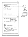
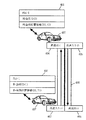
さらに、上述のようなオブジェクトモデル提示情報の詳細な具体例を図7を用いながら説明する。図7は、図4に示されるようなその他情報に対応するオブジェクトモデル提示情報の詳細な具体例を示した図である。
【0107】
図7において、オブジェクトモデル提示情報700は、形状に関する情報701と、時空間の振る舞い方に関する情報702とを含む。形状に関する情報701は、例えば”gas_station.obj”という名称のファイルに格納されている3次元形状情報であってもよい。また、形状に関する情報701は、例えば、ポリゴンの幅、高さ、奥行きの情報と、当該ポリゴンに貼り付けるためのテキスチャを指定する”esso_station.bmp”という名称のファイルとによって構成されてもよい。さらに、形状に関する情報701は、位置情報を含む。図7において、位置情報は、オブジェクトが表示される3次元座標である。なお、図7の右側上部に示された2つの図形は、以上のような形状に関する情報を用いて実際にそれぞれ描画した例を表している。
【0108】
オブジェクトモデル提示情報700に含まれる時空間の振る舞い方に関する情報702は、どのような言語が用いられて表現されてもよいが、典型的にはオブジェクト指向のインタープリタ言語(例えば、Sun Microsystems社が開発したJava言語など)が用いられて表現される。このような言語によって表記されたスクリプトは、コンパイルの必要がないので、即時に実行することができ、作成も容易であるので、本実施形態に好適である。
【0109】
図7の時空間の振る舞い方に関する情報702において、posメソッドは、施設IDに対応する空間座標の位置にオブジェクトを作成する。Dirメソッドは、3次元空間におけるオブジェクトの傾きを表現する。Shapeメソッドは、オブジェクトを描画する。BlinkObjectメソッドは、車とオブジェクトとの距離が所定の数値radius以下になったときに、所定のオブジェクトを点滅させる。したがって、この時空間の振る舞い方に関する情報702は、所定のオブジェクトの位置が車から所定の距離radius内に入るとオブジェクトを点滅させるように記述されている。
【0110】
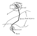
図8は、図7における時空間の振る舞い方に関する情報が実行される状態を説明するための図である。図8において、Road Objectsは地図上の道路を表し、図上方の直方体の図形は地図上に描画されたオブジェクトを表している。ここで、自車は図中の太線によって表される経路Routeに沿って走行しているものとする。まず、図中のposition1に車の位置があるときには、オブジェクトの状態に変化はない。その後、車の位置がposition2に来ると、オブジェクトの位置が車からの所定の半径radius内に入る。すると、図7における時空間の振る舞い方に関する情報が実行されて、当該オブジェクトは点滅することになる。
【0111】
次に、時空間の振る舞い方に関する情報が関数名と関数の内容とを記述した形式で表現される場合について、図9および図10を用いながら説明する。図9は、オブジェクトモデル提示情報格納部6に格納されて、前述の交通情報に対応する関数名と関数の内容を例示した図である。図10は、オブジェクトモデル提示情報格納部6に格納されて、前述の緊急情報、駐車場情報および車間通信情報に対応する関数名と関数の内容を例示した図である。
【0112】
図9において、例えば、VICS等から通信部7を介して渋滞情報が送られてきた場合において、対応する位置が表示しようとする地図内にある場合には、地図データ合成部4は、渋滞情報提示関数を実行する。したがって、図9における関数内容に含まれる番号に従って処理が実行される。すなわち、第1のステップとして、地図データ合成部4は、通信部7から読み込まれたリンク情報と、From情報と、To情報とに対応する道路情報(例えば、当該道路を構成する線素辺を規定するテーブルなど)を地図データ格納部3から読み込む。次に、第2のステップとして、地図データ合成部4は、第1のステップにおいて読み込まれた情報に対応した区間の地図データ表示空間座標を求める。最後に、第3のステップとして、地図データ合成部4は、渋滞をあらわす車ポリゴンや渋滞ビルボードのようなオブジェクトを中間バッファに作成し、表示空間に配置する。以上のようなステップが実行されると、地図空間の中に渋滞を示す車ポリゴン等が作成されて、道路に並べられる。したがって、ユーザは、視線を動かすことなく、直感的に渋滞情報を把握することができる。
【0113】
なお、以上のような処理は、他の通信情報に対しても同様になされ、通信情報に応じてオブジェクトモデル提示情報格納部6に格納されている個別の関数が実行される。これらの関数は、図9および図10に示されたとおりである。
【0114】
次に、上記の渋滞情報提示関数が実行された際の具体的処理例について、さらに詳述する。まず、地図データ合成部4によって通信部7から読み込まれる渋滞情報について図11を参照しながら説明する。
【0115】
図11は、VICS等から通信部7を介して送られてきた渋滞情報の構造例を示した図である。図11の渋滞情報は、渋滞情報ID551と、渋滞リンク番号552と、開始補間点番号553と、終了補間点番号554と、渋滞車線番号555とを含む。なお、これらの情報は、前述した図4の渋滞情報に含まれる、渋滞情報IDと、リンク情報と、From情報と、To情報と、車線情報とにそれぞれ対応している。
【0116】
渋滞情報ID551は、続くリンクデータが渋滞情報であることを識別するための情報識別番号である。渋滞リンク番号552は、渋滞している道路に対応するリンク番号である。例えば、ここに1010が格納されていれば、リンク番号1010の道路が渋滞していることを表す。開始補間点番号553および終了補間点番号554は、渋滞している道路に対応するリンク内の開始補間点および終了補間点を表す。たとえば、開始補間点番号553に1が格納され、終了補間点番号554に2が格納されていれば、リンク番号1010の道路において、補間点1から補間点2までの区間が渋滞していることを表す。渋滞車線番号555は、渋滞が起こっている車線番号である。なお、渋滞情報には複数のリンクデータが含まれてもよいことは前述した。
【0117】
次に、渋滞情報提示関数が実行された場合の処理手順について説明する。図12は、渋滞情報提示関数が実行された場合の処理手順を示したフローチャートである。図12のステップS101において、渋滞情報提示関数が実行されると、まず、地図データ合成部4は、読み込まれた渋滞情報に対応する地図データとの関係を示す情報(以下、対応テーブルという)を地図データ格納部3から読み出す。
【0118】
図13は、地図データ合成部4に格納されている地図データとの関係を示す対応テーブルを例示した図である。図13の対応テーブルは、道路に対応するリンク番号と、その開始および終了補間点番号と、道路数と、シーケンス番号およびその開始・終了背骨点番号の1つ以上の組とを含む。
【0119】
ここで、道路数とは、地図データ格納部3に格納されて、リンク番号に対応する地図データ内の道路の数を表す。シーケンス番号とは、地図データ格納部3に格納されている地図データ内の道路の最小単位であるシーケンスにつけられた番号である。このシーケンスは、直線や折れ線、曲線などで構成されており、その制御点を背骨点と呼ぶ。背骨点は、1つのシーケンスに対して2つ以上が設けられ、連続番号が付されている。従って、シーケンス番号と、開始背骨点番号と、終了背骨点番号との組によって、地図データ中の任意の線素辺を一意的に示すことができる。
【0120】
なお、ここで示されるシーケンス番号と、開始背骨点番号と、終了背骨点番号との組は、地図データのデータ構造により異なるが、地図データ中の任意の線素辺を一意的に示すことができるデータであれば、これらの組に限られず、どのようなデータであってもよい。
【0121】
次に、図12のステップS102において、地図データ合成部4は、読み出された前述の対応テーブルの情報から、地図データ内の道路の数を抽出する。図13の対応テーブル例によれば、道路の数は3つである。
【0122】
そして、ステップS103において、地図データ合成部4は、抽出された道路数と処理済みの道路数とを比較し、これらが等しくなれば道路数分の処理が終了したと判定して、処理はステップS108へジャンプする。終了しない場合には、処理はステップS104へ進む。
【0123】
ステップS104において、地図データ合成部4は、前述のステップS101において読み出した各シーケンス番号、開始背骨点番号および終了背骨点番号のうち、所定の一組(初期値では最初の一組)に対応する3次元座標点を地図データ格納部3より検索して読み出す。なお、当該3次元座標点は、地図データとは別に設けられた所定のテーブルに格納されていてもよいし、地図データそのものから算出されてもよい。また、ここでは2次元座標点が用いられてもよい。
【0124】
次に、ステップS104において、地図データ合成部4は、読み出された3次元座標点を修正するオフセット処理を行う。なぜなら、読み出された座標点列は、道路の中央線に対応するので、前述の渋滞情報に含まれる渋滞車線番号555が示す車線に対応させるために、その中央位置を計算する必要があるからである。ここで、車線番号が1である場合には、補間点番号1から2の方向へ向かって左側の車線を表すものとし、左車線の中央部点列を求める。
【0125】
さらに、ステップS104において、地図データ合成部4は、実行中の渋滞情報提示関数が指定する車の3次元モデルを並べようとする位置や大きさ、数、向きなどを、左車線中央部点列を補間するようにして算出する。
【0126】
以上のように或る道路に関する処理を終了すると、ステップS105において、地図データ合成部4は、処理済みの道路数をインクリメントし、読み出された各シーケンス番号、開始背骨点番号および終了背骨点番号のうち、次の道路に関する処理を行うために、所定の一組を選出する。その後、処理はステップS103へ戻る。
【0127】
全ての処理が終了すれば、ステップS108において、地図データ合成部4は、地図データ格納部3またはオブジェクトモデル提示情報格納部6から車のモデルデータを読み出す。次に、地図データ合成部4は、ステップS106で求められた車モデルのそれぞれの位置や大きさ、数、向きなどを参照して、地図データと合成して表示器5に表示できるように、中間バッファに配置する。なお、車モデルは、3次元モデルに限られず、2次元モデルであっても、実写画像であってもよい。
【0128】
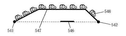
図14は、以上のように配置された車モデルと道路の関係を示すために、地図平面に対して垂直方向の上空から見下ろした地図の模式図である。図14において、道路546は補間点541および542を有するリンク番号1000の道路を表し、道路547は補間点543および544を有するリンク番号1010の道路を表すものとする。また、図13の対応テーブルが示すように、リンク番号1010の道路は、3つのシーケンスで構成されており、図14におけるシーケンス5471〜5473に対応する。したがって、シーケンス5471のシーケンス番号は15であり、開始背骨点番号は0であり、終了背骨点番号は1である。同様に、シーケンス5472のシーケンス番号は14であり、開始背骨点番号は0であり、終了背骨点番号は1である。また、シーケンス5473のシーケンス番号は13であり、開始背骨点番号は0であり、終了背骨点番号は1である。さらに、図15は、図14が示す地図を補間点544から補間点543の方向へ地上高から見た側面図である。
【0129】
図14および図15を参照すれば、地上高にあるリンク番号1000の道路546に対して、リンク番号1010の道路547が立体交差しており、リンク番号1010の道路547の左車線が渋滞していることがわかる。なお、実際に表示される場合には、地図は3次元で表示されてもよいし、2次元で表示されてもよい。また、車モデル548の表示についても同様である。
【0130】
以上のような渋滞情報提示関数の処理は、工事中の車線規制情報の表示に関しても同様の手順で行うことができる。もちろん、前述した渋滞情報における渋滞情報IDが工事中情報IDに置き換わり、道路上に並べるモデルが車から、工事中を示す看板や人形などのモデルに置き換わることになる。このように、図9および図10に示される関数の処理も同様に行うことができる。
【0131】
以上のように図5のサブルーチンステップS133の処理が終了すると、次に、ステップS134において、地図データ合成部4は、通信部7から読み込まれた情報がすべて実行されたかどうかを確認する。全て実行されている場合には、地図データ合成部4は、サブルーチンステップS13の処理を終了し、図3のフローに復帰する。未だ全て実行されていない場合には、地図データ合成部4は、処理をステップS132まで戻して、一連の処理を繰り返す。図3において、サブルーチンステップS13の処理が終了すると、地図データ合成部4は、合成した地図データを表示器5に送る。表示器5は、地図画面をユーザに対して表示する。
【0132】
図16は、以上のような処理を経て生成された地図画面の一表示例を示した図である。図16において、ビル群を含む3次元景観上には、パトカーの位置を示す車ポリゴンと、渋滞を示す渋滞ビルボードと、工事中であることを示すアニメーション図形とが配置されている。したがって、ユーザは、視線を動かすことなく、直感的に各種情報を把握することができる。
【0133】
さらに、図5のサブルーチンステップS133における地図データ合成部4の詳細な処理を説明する前提として、まず、地図データ合成部4の詳細な構成を図17および図18を用いながら説明する。
【0134】
図17は、地図データ合成部4の詳細な構成を示したブロック図である。図17において、地図データ合成部4は、オブジェクトモデル提示情報格納部6、入力部2および通信部7からの情報が入力されて、オブジェクトモデル提示情報を実行するオブジェクト提示情報実行部41と、オブジェクト提示情報実行部41および地図データ格納部3からの地図データが入力されて、表示データを合成する表示データ合成部42とを含む。
【0135】
オブジェクト提示情報実行部41は、割り込みイベントを検出して各イベントに対応したコマンドを実行する。また、オブジェクト提示情報実行部41は、オブジェクトモデル提示情報を実行してオブジェクトデータを作成し、表示データ合成部42へ送る。表示データ合成部42は、送られてきたオブジェクトデータと地図データとを合成して、表示器5へ出力する。
【0136】
次に、オブジェクト提示情報実行部41の詳細な構成を説明する。図18は、オブジェクト提示情報実行部41の詳細な構成を示したブロック図である。図18において、オブジェクト提示情報実行部41は、オブジェクト提示情報制御部411と、解釈実行部412とを含む。
【0137】
オブジェクト提示情報制御部411は、オブジェクトモデル提示情報格納部6、入力部2および通信部7からの情報が入力されて、各イベントに対応した制御を行う。解釈実行部412は、オブジェクト提示情報制御部411から送られてきたオブジェクト作成依頼ないしオブジェクト属性変更依頼に従い、オブジェクトモデル提示情報を解釈・実行してオブジェクトデータを生成し、オブジェクト提示情報制御部411へ出力する。
【0138】
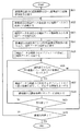
以上を前提にして、図5のサブルーチンステップS133における地図データ合成部4の詳細な処理を説明する。図19は、サブルーチンステップS133の詳細な処理を示したフローチャートである。
【0139】
図19のステップS91において、オブジェクト提示情報実行部41は、通信部7、入力部2またはタイマー割り込みからの割り込みイベントを検出する。典型的には、他から割り込みがかからない限り、オブジェクト提示情報実行部41は、割り込みイベントが検出されるまで、ステップS91の処理を繰り返す。
【0140】
割り込みイベントが検出されると、ステップS92において、オブジェクト提示情報実行部41は、当該イベントを解析し、イベントに対応した処理を実行する。ここでは、イベントは、更新イベント、提示条件発火イベント、作成イベント、属性変更イベントの4つが規定されている。解析されたイベントが更新イベントであれば、処理はステップS94へ進む。解析されたイベントが提示条件発火イベントであれば、処理はステップS95へ進む。解析されたイベントが作成イベントであれば、処理はステップS96へ進む。解析されたイベントが属性変更イベントであれば、処理はステップS98へ進む。
【0141】
ステップS94(更新イベント)において、オブジェクト提示情報実行部41は、通信部7よりオブジェクトモデル提示情報の更新情報を読み込み、オブジェクトモデル提示情報格納部6へ更新情報を格納する。当該更新情報は、オブジェクトモデル提示情報格納部6に格納されている対応するオブジェクトモデル提示情報の全部であってもよいし、一部であってもよい。以上の処理が終了すると、地図データ合成部4は、サブルーチンステップS133の処理を終了し、図5のフローへ復帰する。
【0142】
ステップS95(提示条件発火イベント)において、オブジェクト提示情報実行部41は提示条件発火イベントの内容を解析し、提示条件の設定を変更する。以上の処理が終了すると、地図データ合成部4は、サブルーチンステップS133の処理を終了し、図5のフローへ復帰する。
【0143】
ステップS96(作成イベント)において、オブジェクト提示情報制御部411は、オブジェクトモデル提示情報格納部6から対応するオブジェクトのオブジェクトモデル提示情報を読み込み、解釈実行部412にその情報を送信し、オブジェクトの作成処理を依頼する。さらに、ステップS97において、解釈実行部412は、送られてきたオブジェクトの形状に関する情報と時空間の振る舞いに関する情報(典型的には簡易言語や関数表現で作成された情報)を解釈実行し、オブジェクトモデル提示条件の設定や提示処理を行い、オブジェクト提示情報制御部411に制御を戻す。このようなオブジェクトモデル提示情報の構造および実行例については、前述した。
【0144】
次に、ステップS99において、オブジェクト提示情報実行部41は、解釈実行部412で実行されたオブジェクトの提示情報の実行結果を表示データ合成部42に送り、地図データに合成する。以上の処理が終了すると、地図データ合成部4は、サブルーチンステップS133の処理を終了し、図5のフローへ復帰する。
【0145】
ステップS98(属性変更イベント)において、オブジェクト提示情報制御部411は、位置や大きさなどオブジェクトの属性変更処理を行うように、解釈実行部412に依頼する。次に、ステップS99において、オブジェクト提示情報実行部41は、前述のような処理を行う。以上の処理が終了すると、地図データ合成部4は、サブルーチンステップS133の処理を終了し、図5のフローへ復帰する。
【0146】
さらに、図19のステップS99において、表示データ合成部42が地図画面をどのように生成するかを詳述する。まず、生成される地図画面が2次元景観である場合について説明する。図20は、2次元景観を作成する場合における表示データ合成部42の詳細な構成を示した図である。図20において、表示データ合成部42は、二次元オブジェクト作成部145と、二次元データ合成部146とを含む。
【0147】
二次元オブジェクト作成部145は、オブジェクト提示情報実行部41からのオブジェクトモデル提示情報が入力されて、二次元のオブジェクトを作成する。二次元データ合成部146は、二次元オブジェクト作成部145が作成した二次元のオブジェクトと、地図データ格納部3からの2次元地図データとを入力されて、互いのデータにおける2次元座標データを基に、ユーザに表示すべき地図画像を合成する。
【0148】
次に、表示データ合成部42において生成される地図画面が、3次元景観である場合について説明する。ここで、生成される地図画面が3次元景観であっても、オブジェクトモデル提示情報から作成されるオブジェクトおよび地図データ格納部3に格納されている地図データは、必ずしも3次元のデータである必要はない。そこでまず、表示データ合成部42が、オブジェクト提示情報実行部41からは3次元のデータが入力され、地図データ格納部3からは2次元の地図データが入力されて、3次元景観の地図画面を生成する場合について説明する。
【0149】
図21は、オブジェクト提示情報実行部41からは3次元のデータが入力され、地図データ格納部3からは2次元の地図データが入力されて、鳥瞰図の地図画面を生成する、表示データ合成部42の詳細な構成について説明したブロック図である。
【0150】
図21において、表示データ合成部42は、地図データ格納部3から2次元の地図データが入力されて鳥瞰図の形の地図データに変形する鳥瞰図データ変形部141と、オブジェクト提示情報実行部41から3次元のデータが入力されて三次元のオブジェクトを作成する三次元オブジェクト作成部142と、鳥瞰図データ変形部141からのデータおよび三次元オブジェクト作成部142からのデータが入力されてそれらを合成する三次元データ合成部143とを含む。
【0151】
鳥瞰図データ変形部141は、地図データ格納部3から2次元の地図データが入力されて、鳥瞰図の形の地図データに変形する。2次元データから鳥瞰図を作成する方法については、例えば、「鳥瞰図地図表示ナビゲーションシステムの開発」(社団法人 自動車技術会 学術講演前刷集962 1996−5)等に開示されている。以下、2次元データから鳥瞰図を作成する方法について説明する。
【0152】
図22は、二次元の地図データに対して透視投影変換を施して鳥瞰図を作成する方法を説明した図である。図22において、V(Vx,Vy,Vz)は視点の座標を表す。S(Sx,Sy)はモニター上の鳥瞰図画像の座標を表す。M(Mx,My,Mz)は2次元地図上の座標を表す。なお、地図データは二次元のデータであるから、Mzは0である。E(Ex,Ey,Ez)は視点座標系で見た点Mの相対位置を表す。θは視線の見下ろし角を表し、φは視線の方向角を表す。DSは視点と画面との間の理論的距離を表す。
【0153】
ここで、視点の座標V(Vx,Vy,Vz)と、視線の見下ろし角θと、視線の方向角φとを定めれば、2次元地図上の座標M(Mx,My,Mz)に対して、鳥瞰図画像の座標S(Sx,Sy)を求めることができる。その算出式は、次式(1)のように表すことができる。
【数1】

鳥瞰図データ変形部141は、例えば上式(1)の計算を行って、地図データ格納部3から入力された2次元の地図データを、鳥瞰図の形の地図データに変形する。鳥瞰図の形に変形された3次元の地図データは、三次元データ合成部143へ入力される。
【0155】
また、三次元オブジェクト作成部142は、オブジェクト提示情報実行部41から3次元のデータが入力されて、前述した図5のサブルーチンステップS133における処理を行い、3次元のオブジェクトを作成する。生成されたオブジェクトは、三次元データ合成部143へ入力される。
【0156】
三次元データ合成部143は、入力された3次元地図データおよびオブジェクトのデータを合成して、表示器5に出力する。図23は、このようにして作成されたデータを表示器5が表示する場合の一例を示した図である。
【0157】
図23において、鳥瞰図の形に表示された地図上には、工事中を示す3次元のオブジェクトと、駐車場の満車を示すオブジェクトとが配置されている。なお、図23において、これらのオブジェクトは2次元のオブジェクトのように見えたとしても、これらは視点が変化することによってその形状が変化するような3次元のオブジェクトを表しているものとする。
【0158】
次に、オブジェクト提示情報実行部41からは3次元のデータが入力され、地図データ格納部3からは2次元の地図データが入力されて、上述のような鳥瞰図とは異なる3次元景観の地図画面が生成される場合について説明する。
【0159】
図24は、オブジェクト提示情報実行部41からは3次元のデータが入力され、地図データ格納部3からは2次元の地図データが入力されて、鳥瞰図とは異なる3次元景観の地図画面を生成する、表示データ合成部42の詳細な構成について説明したブロック図である。
【0160】
図24において、表示データ合成部42は、地図データ格納部3から2次元の地図データが入力されて3次元の地図データを生成する三次元地図データ作成部147と、オブジェクト提示情報実行部41から3次元のデータが入力されて三次元のオブジェクトを作成する三次元オブジェクト作成部142と、三次元地図データ作成部147からのデータおよび三次元オブジェクト作成部142からのデータが入力されてそれらを合成する三次元データ合成部143とを含む。
【0161】
図24において、三次元オブジェクト作成部142と、三次元データ合成部143とは、図21における場合と同様の構成および動作を行う。したがって、これらの説明は省略し、以下、三次元地図データ作成部147の構成および動作について説明する。
【0162】
図25は、三次元地図データ作成部147の詳細な構成を示したブロック図である。図25において、三次元地図データ作成部147は、地図データ格納部3からは2次元の地図データが入力されて、高さおよび幅の情報を付与する高さ・幅情報付与部1471と、高さ・幅情報付与部1471からのデータが入力されて3次元のオブジェクトを作成する3次元ポリゴン作成部1472とを含む。
【0163】
高さ・幅情報付与部1471は、入力された二次元の地図データに含まれるリンクの種類(例えば、側道リンクや高架リンクなど)および分岐ノードの情報を利用し、典型的には所定のパターンをあてはめて、道路等の3次元形状を解析する。解析の結果から、高さ・幅情報付与部1471は、当該道路等の2次元データに対して、高さおよび幅の情報を付与し、3次元の地図データを生成する。
【0164】
3次元ポリゴン作成部1472は、高さ・幅情報付与部1471から3次元の地図データを入力され、一般的なポリゴン作成手法を用いて、3次元のオブジェクトを作成する。以上のように、図24の表示データ合成部42は、鳥瞰図とは異なる3次元景観の地図画面を生成する。
【0165】
次に、表示データ合成部42が、オブジェクト提示情報実行部41からは2次元のデータが入力され、地図データ格納部3からは3次元の地図データが入力されて、3次元景観の地図画面を生成する場合について説明する。
【0166】
図26は、オブジェクト提示情報実行部41からは2次元のデータが入力され、地図データ格納部3からは3次元の地図データが入力されて、3次元景観の地図画面を生成する、表示データ合成部42の詳細な構成について説明したブロック図である。
【0167】
図26において、表示データ合成部42は、オブジェクト提示情報実行部41から2次元のデータが入力されて2次元のオブジェクトを作成する二次元オブジェクト作成部145と、二次元のオブジェクトデータが入力されて3次元座標に変換する二次元/三次元座標変換部144と、地図データ格納部3から3次元の地図データが入力され、二次元/三次元座標変換部144からの三次元のオブジェクトが入力されてそれらを合成する三次元データ合成部143とを含む。
【0168】
図26において、二次元オブジェクト作成部145は、オブジェクト提示情報実行部41から2次元のデータが入力されて、前述した図5のサブルーチンステップS133における処理を行い、2次元のオブジェクトを作成する。
【0169】
具体的には、前述のように、オブジェクトモデル提示情報に含まれる2次元の形状情報として、複数の画像ファイルが用意される。図27は、オブジェクトモデル提示情報に含まれる2次元の形状情報として用意された複数の画像ファイルを例示した図である。図27において、複数の画像はそれぞれ、事故画像と、工事中画像と、渋滞画像との種類に分かれている。これらの画像の種類は、各オブジェクトモデル提示情報に対応している。また、各種類の画像にはさらに、遠距離用と、中距離用と、近距離用とに分かれている。
【0170】
まず、二次元オブジェクト作成部145は、オブジェクトモデル提示情報に対応する画像の種類を決定する。次に、二次元オブジェクト作成部145は、決定された画像の種類の中から、遠距離用の画像、中距離用の画像および近距離用の画像のいずれかを選択する。ここで、前述のように、オブジェクトモデル提示情報には形状に関する情報としてオブジェクトの位置を表す位置情報が含まれる。当該位置情報は、3次元座標によって表されている。図27において、遠距離用の画像と、中距離用の画像と、近距離用の画像は、オブジェクトの位置を表す3次元座標と視点座標との距離に従って決定される。したがって、典型的には、二次元オブジェクト作成部145は、オブジェクトの位置を表す3次元座標と視点座標との距離を計算して、当該距離が予め定められたどの距離の範囲に含まれるかを判別する。
【0171】
二次元/三次元座標変換部144は、生成された2次元のオブジェクトにおける2次元座標を、対応する前述した位置情報に基づいて3次元座標に変換する。変換された3次元のオブジェクトデータは、三次元データ合成部143へ入力される。
【0172】
三次元データ合成部143は、地図データ格納部3から3次元の地図データを入力される。三次元データ合成部143は、入力された地図データと、二次元/三次元座標変換部144から入力された3次元のオブジェクトデータとを合成して、3次元景観の地図画面を作成する。作成された3次元景観の地図画面は、表示器5へ入力される。
【0173】
また、以上のような構成によれば、二次元オブジェクト作成部145において作成された2次元のオブジェクトは、二次元/三次元座標変換部144において3次元のデータに変換された後、三次元データ合成部143において3次元の地図データと合成される。しかし、図26の表示データ合成部42は、二次元/三次元座標変換部144が省略され、三次元データ合成部143に替えて二次元/三次元画像合成部が設けられるように構成されてもよい。ここで、二次元/三次元画像合成部は、二次元オブジェクト作成部145において作成された2次元のオブジェクトを3次元景観の地図画面上に貼り付ける形で合成する。具体的には、二次元/三次元画像合成部は、3次元の地図データをスクリーン座標へ変換して3次元景観の地図画面を生成し、2次元のオブジェクトのスクリーン座標を計算して、生成された3次元景観の地図画面に対して2次元データのまま合成する。このように構成すれば、視点の移動に従って、オブジェクトの形が変形することなく、常に画面に対して平行に表示される。したがって、視認性のよいオブジェクト表示を行うことができる。
【0174】
図28は、図26の表示データ合成部42によって作成された3次元景観の地図画面を例示した図である。図28に示されるように、図の左側には工事中を示すオブジェクトが表示され、図の中央には、事故を示すオブジェクトが表示され、その右下方へ配置された道路上に渋滞の発生を示すオブジェクトが表示されている。表示されている渋滞の発生を示すオブジェクトは、前述のように視点座標との距離に従って、画面手前に近づくほど大きく表示されている。したがって、2次元のオブジェクトが用いられる場合であっても、3次元景観上においてユーザに奥行きを感じさせることができる。
【0175】
最後に、表示データ合成部42が、オブジェクト提示情報実行部41からは2次元のデータが入力され、地図データ格納部3からは2次元の地図データが入力されて、3次元景観の地図画面を生成する場合について説明する。
【0176】
このような3次元景観の地図画面を生成する表示データ合成部42は、図20の表示データ合成部42に対して、図21における鳥瞰図データ変形部141または図24における三次元地図データ作成部147をさらに含むように構成すれば、前述と同様の構成部を用いて構成することができる。
【0177】
すなわち、以上のような表示データ合成部42は、オブジェクト提示情報実行部41から2次元のデータが入力されて2次元のオブジェクトを作成する二次元オブジェクト作成部145と、二次元のオブジェクトデータが入力されて3次元座標に変換する二次元/三次元座標変換部144と、地図データ格納部3から2次元の地図データが入力されて鳥瞰図の形の地図データに変形する鳥瞰図データ変形部141または3次元の地図データを生成する三次元オブジェクト作成部142と、鳥瞰図データ変形部141または三次元オブジェクト作成部142からの3次元地図データおよび二次元/三次元座標変換部144からの三次元のオブジェクトデータが入力されてそれらを合成する三次元データ合成部143とを含む。このような表示データ合成部42における各構成部の動作は前述と同様であるので、説明を省略する。
【0178】
以上のように、表示データ合成部42がオブジェクト提示情報実行部41から2次元のデータを入力されて3次元景観の地図画面を生成する場合には、オブジェクトモデル提示情報格納部6は、3次元データよりもデータ量の少ない2次元データを格納する。したがって、オブジェクトモデル提示情報格納部6は、一定の容量であれば、3次元データを格納する場合よりも多くの種類のオブジェクトデータを格納することができ、同種のデータを格納する場合であれば、容量を少なくすることができる。
【0179】
さらに、表示データ合成部42がオブジェクト提示情報実行部41から2次元のデータを入力されて3次元景観の地図画面を生成する場合には、ユーザは2次元のオブジェクトが用いられていても、直感的に情報を把握することができる。例えば、ユーザが道路を走行中であって、進行方向に渋滞や事故が発生している場合には、3次元景観の地図画面において渋滞や事故が発生していることを示すオブジェクトが表示されることによって、ユーザは直感的に情報を把握することができる。
【0180】
図29は、3次元景観の地図画面上に、渋滞が発生していることを示す2次元のオブジェクトが表示される場合を例示した図である。図29に示されるように、複数の渋滞を示すオブジェクトが表示されることによって、進行方向が渋滞していることを直感的に把握することができる。
【0181】
また、図30は、3次元景観の地図画面上に、事故が発生していることを示す2次元のオブジェクトが表示される場合を例示した図である。図30に示されるように、複数の事故を示すオブジェクトが表示されることによって、進行方向に事故が発生していることを直感的に把握することができる。
【0182】
さらに、例えば、ユーザが道路を走行中であって、前方に工事中の道路が存在する場合には、3次元景観の地図画面において工事中であることを示すオブジェクトが表示されることによって、ユーザは工事中の道路を直感的に把握することができる。また、典型的には視点位置が前方に進行した場合には、オブジェクトの大きさが拡大されることによって、ユーザは工事中の道路をより直感的に把握することができる。
【0183】
図31は、3次元景観の地図画面上に、工事中であることを示す2次元のオブジェクトが表示される場合を例示した図である。また、図32は、図31から視点位置がさらに前方へ移動した場合において、3次元景観の地図画面上に、工事中であることを示す2次元のオブジェクトが表示される場合を例示した図である。図31および図32に示されるように、視点位置の進行に伴ってオブジェクトの大きさが拡大されることによって、ユーザは工事中の道路をより直感的に把握することができる。
【0184】
(第2の実施形態)
図33は、本発明の第2の実施形態に係るナビゲーション装置の構成を示すブロック図である。図33において、本ナビゲーション装置は、入力部2と、地図データ格納部3と、地図データ合成部4と、表示器5と、オブジェクトモデル提示情報格納部6と、通信部7、位置検出部9と、経路選出部10と、誘導部11とを備えている。
【0185】
ここで、図33のナビゲーション装置における入力部2と、地図データ格納部3と、地図データ合成部4と、表示器5と、オブジェクトモデル提示情報格納部6と、通信部7とは、図1の地図表示装置において対応するそれぞれの構成部とほぼ同様の構成および動作を行う。また、図33のナビゲーション装置における位置検出部9と、経路選出部10と、誘導部11との構成および動作は、図47のナビゲーション装置において対応するそれぞれの構成部とほぼ同様の構成および動作を行う。
【0186】
以上のような図33のナビゲーション装置の構成は、図1における地図表示装置と同様に、一般的なコンピュータシステムにおいて実現することができる。図34は、一般的なコンピュータシステムにおいて実現された図33におけるナビゲーション装置の構成を示した図である。
【0187】
図34において、本ナビゲーション装置は、CPU342と、ROM343と、RAM344と、出力部345と、入力部346と、位置検出部349と、通信部338とを備えている。これらは共通のバスによって結合されている。ここで、ROM343およびRAM344は、図2のROM333およびRAM334と同様に、外部記憶媒体を用いた記憶装置を含むことができるものとする。
【0188】
また、位置検出部349は、GPS、電波ビーコン受信装置、車速センサ、角速度センサ、絶対方位センサ等で構成される。さらに、位置検出部349が電波または光のビーコン受信装置で構成される場合であって、電波または光のビーコン信号に前述のような外部からの情報が含まれている場合には、通信部338は省略されてもよい。その場合には、図33における通信部7の機能は、位置検出部349に含まれることになる。
【0189】
図34において、本ナビゲーション装置のCPU342は、ROM343および/またはRAM344に記憶されたプログラムに従って動作する。したがって、図33における地図データ合成部4、経路選出部10および誘導部11の各機能は、それぞれ対応するプログラムによって実現される。その場合、本ナビゲーション装置は、典型的には当該ソフトウェア制御のためのプログラムを記憶した記録媒体を実装することになる。もちろん、本装置は、通信回線から伝送されてくるプログラムを利用してもよい。
【0190】
また、典型的には図33における地図データ格納部3は、ROM343に含まれる。もっとも、地図データ格納部3の全部または一部は、RAM344に含まれてもよい。同様に、オブジェクトモデル提示情報格納部は、RAM344に含まれるが、ROM343に含まれてもよい。
【0191】
このように、図33に示された第2の実施形態に係るナビゲーション装置は、従来のナビゲーション装置と同様に動作する部分を除いて、図1に示された第1の実施形態に係る地図表示装置とほぼ同様に動作する。以下、本ナビゲーション装置における基本的な動作について、図35を用いながら説明する。
【0192】
図35は、第2の実施形態に係るナビゲーション装置の基本的な処理の流れを表したフローチャートである。図35のステップS51において、経路選出部10は、入力部2から目的地や表示した地図領域がユーザによって指定され、位置検出部9から自車位置が渡されて経路探索を行い、誘導部11に経路探索結果を渡す。
【0193】
次に、ステップS52において、誘導部11は、位置検出部9の自車位置に対応する該当領域の地図表示を行うため、地図データ合成部4に地図データ合成表示を依頼する。さらに、ステップS53において、地図データ合成部4は、地図データ格納部3から地図データを読み込む。ステップS54において、誘導部11は、通信部7から通信情報を読み込んで、地図データ合成部4に渡す。サブルーチンステップS55において、地図データ合成部4は、読み込まれた通信情報とオブジェクトモデル提示情報格納部6に格納されている情報を参照してオブジェクトを作成し、地図データに合成する。
【0194】
ここで、図35のステップS53からサブルーチンステップS55までの処理は、図3のステップS11からサブルーチンステップS13までの処理にほぼ対応する。したがって、図35のサブルーチンステップS55における処理の詳細も、図5における処理の詳細と同様である。よって、以上の処理内容の説明は省略する。
【0195】
最後に、図35のステップS56において、誘導部11は、位置検出部9の自車位置から目的地に到着するまで誘導案内を続行するので、処理はステップS52へ戻る。また、誘導部11は、目的地に到着したと判断した場合には、誘導案内を終了する。
【0196】
以上のように、第2の実施形態に係るナビゲーション装置は、第1の実施形態に係る地図表示装置とほぼ同様に、誘導案内時において、ユーザが視線を動かさず、より直感的に情報を把握することができ、また、送受信する情報量が僅少でありながら、オブジェクトを記憶するための記憶媒体の容量を小さくすることができる。
【0197】
(第3の実施形態)
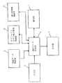
図36は、本発明の第3の実施形態に係る地図表示装置の構成を示すブロック図である。図36において、本地図表示装置は、入力部2と、地図データ格納部3と、地図データ合成部4と、表示器5と、オブジェクトモデル提示情報格納部6と、通信部7と、通行券情報格納部12とを備えている。なお、通行券情報格納部12は、本地図表示装置に対して着脱自在に装着された半導体カードや磁気カードなどによって実現されてもよい。
【0198】
本地図表示装置は、図1の地図表示装置に加えて通行券情報格納部12をさらに備えている以外は、図1の地図表示装置と同様の構成部を備える。したがって、同様の構成部には同一の番号を付してその説明を省略する。もっとも、本地図表示装置は、外部の図示されていない自動料金徴収センタまたは各料金所と通信部7とが必ず双方向で通信し、地図データ合成部4と通信部7とのデータ通信も双方向で行われる点が、必ずしも双方向の通信を要しない図1の地図表示装置とは異なる。また、本地図表示装置は、自動料金徴収システムの端末として動作するので、地図データ合成部4の動作も異なる。以下、その動作について詳述する。
【0199】
図37は、自動料金徴収システムの端末として動作する地図データ合成部4の処理内容を表したフローチャートである。図37のステップS611において、地図データ合成部4は、地図データ格納部3から地図データを読み込む。次に、ステップS612において、地図データ合成部4は、通信部7から自動料金徴収センタまたは各料金所が送信する料金所情報を読み込む。典型的には、料金所情報には、料金所IDと当該料金所の位置座標とが含まれる。さらに、サブルーチンステップS613において、地図データ合成部4は読み込まれた料金所情報とオブジェクトモデル提示情報格納部6に格納されている情報とを参照して料金所のオブジェクトを作成し、地図データに合成する。
【0200】
以上のような処理は、図3の各処理にそれぞれ対応してほぼ同一である。すなわち、図37のステップS611は、図3のステップS11と同様であり、図37のステップS612は、図3のステップS12と同様であり、図37のサブルーチンステップS613は、図3のサブルーチンステップS13と同様である。したがって、これらの処理の詳細な説明は省略する。
【0201】
もっとも、図37における料金所情報は、前述した通信情報とは異なって単なるランドマーク情報であってもよいし、料金の情報を含んでいてもよい。したがって、料金所情報は必ずしも通信部7から読み込まれる必要はなく、サブルーチンステップS613において、オブジェクトモデル提示情報格納部6に格納されている情報のみからオブジェクトが作成されてもよい。その場合には、ステップS612は省略される。
【0202】
次に、図37のステップS614において、地図データ合成部4は、通信部7からの駅通過イベント割り込み情報があったかを判断する。具体的には、ユーザが携帯した本地図表示装置が駅の出入り口を通過すると、自動料金徴収センタまたは駅の出入り口に対応する料金所から駅通過イベント割り込み情報が送信される。駅通過イベント割り込み情報は、入り口イベント情報または出口イベント情報を含むが、その内容については後述する。地図データ合成部4は、通信部7によって当該情報が受信されたか否かを判断する。当該情報が受信されていなければ、地図データ合成部4は、処理を終了する。もっとも、図37の処理は、典型的には一定の時間ごとに行われるので、ステップS614における判断は繰り返しなされることになる。当該情報が受信されていれば、処理はステップS615へ進む。
【0203】
ステップS615において、地図データ合成部4は、受信された駅通過イベント割り込み情報を解析し、入口イベント情報が受信されたとき、または出口イベント情報が受信されたときには、対応するオブジェクトモデル提示情報格納部6に格納されているオブジェクトモデル提示情報を実行し、表示器5上に所定のシンボルないしオブジェクトモデルを表示する。典型的には、表示されている料金所のシンボル内に利用区間や支払履歴、料金等の情報を表示する。
【0204】
図38は、ステップS615において表示される所定のシンボルを例示した図である。図38において、2つのシンボル、すなわち、料金所シンボル1001および料金情報シンボル1002が示されている。料金所シンボル1001は、典型的には、前述の料金所情報に対応する料金所の位置に地図と共に表示される。料金情報シンボル1002は、例えば、出口イベント情報を受信した場合に、乗車駅および降車駅の情報と、その料金とを示す。当該料金は、本地図表示装置が所定のテーブルを参照して算出してもよいし、乗車駅および降車駅の情報を自動料金徴収センタ等へ送信し、そこで計算された結果を受信してもよい。
【0205】
なお、これらのシンボルは、後述するサブルーチンステップS616における通行券購入・使用処理の後で表示されてもよい。したがって、本ステップS615は、サブルーチンステップS616の後に行われてもよいし、共に行われてもよい。
【0206】
次に、サブルーチンステップS616において、地図データ合成部4は、入口イベント情報が受信された後、さらに出口イベント情報が受信され、後述する所定の条件を満たしたときには、各種通行券を使用または購入する処理を行う。通行券には、例えば定期券や回数券などが含まれる。定期券とは、所定の区間を所定の期間だけ通行することができる権利または当該権利を表すデータをいう。回数券とは、所定の料金区間を所定の回数だけ通行することができる権利または当該権利を表すデータをいう。さらに、地図データ合成部4は、通信部7を介して、典型的には自動料金徴収センターに課金処理を依頼する。処理を依頼された自動料金徴収センタは、本地図表示装置のユーザを判別して所定の課金処理を行う。以下、サブルーチンステップS616の処理内容について詳説する。
【0207】
図39は、図37のサブルーチンステップS616における処理の詳細を示したフローチャートである。図39のステップS6161において、地図データ合成部4は、入り口または出口の料金所IDを所定の領域に格納する。典型的には前述したように、当該料金所IDは、通信部7によって受信された情報に含まれている。
【0208】
ステップS6162において、地図データ合成部4は、ステップS6161において格納された料金所IDが出口料金所か否かを判定する。出口であれば、処理はステップS6163へ進む。出口でない場合には、サブルーチン処理は終了し、図37の処理へ復帰する。
【0209】
ステップS6163において、地図データ合成部4は、通行券情報格納部12に格納されている通行券情報を参照して、入り口料金所IDが示す乗車駅から出口料金所IDが示す降車駅までの区間で定期券を使用することができるか判断する。使用することができる場合には、サブルーチン処理は終了し、図37の処理へ復帰する。なお、ここで、定期券が使用された旨のメッセージやアニメーション等が表示されてもよい。また、定期券を使用することができない場合、例えば、未購入の場合や、区間外、有効期限切れの場合には、処理はステップS6164へ進む。
【0210】
なお、有効期限切れの場合には、地図データ合成部4は、その旨の警告メッセージを表示器5に表示して、ユーザに定期券の購入を促してもよい。また、使用することができる場合であっても、有効期限が迫ってきている場合には、その旨の警告メッセージを表示器5に表示してもよい。
【0211】
図40は、通行券情報格納部12に格納されている通行券情報を例示した図である。図40において、通行券情報は、典型的には回数券情報620と定期券情報630とを含む。なお、これらの通行券情報は、容易に改竄することができないように、ユーザが通常の方法ではアクセスすることのできないセキュア領域に保存されることが望ましい。または、通行券情報は暗号化され、その復号鍵がセキュア領域に保存されることが望ましい。典型的には、当該セキュア領域は装置内に挿入されたICカード内に確保される。さらに、通行券情報自体は料金所や自動料金徴収センタが保持し、必要に応じて本地図表示装置が情報を要求してもよい。
【0212】
ここで、回数券情報620は、回数券ID621と、入り口ID622と、出口ID623と、料金624と、残り回数625とを含む。なお、回数券情報620は有効期限を含んでもよい。定期券情報630は、定期券ID631と、入り口ID632と、出口ID633と、料金634と、有効期限635とを含む。ここで、回数券ID621および定期券ID631とは、自動料金徴収センタまたは各料金所が送信する回数券情報および定期券情報に与えられた固有の識別番号である。入り口ID622および632と出口ID623および633とは、入り口および出口の料金所IDである。
【0213】
なお、通行券情報は、後述する定期券・回数券購入処理を経て、初めて作成されるので、装置起動当初にはデータが存在しない。また、これらの通行券情報は、それぞれが複数存在してもよい。さらに、通行券情報は、回数券および定期券以外の新たな種別の通行券情報を含んでいてもよい。
【0214】
次に、図39のステップS6164において、地図データ合成部4は、入り口料金所IDと出口料金所IDとの区間において回数券を使用することができるか判断する。使用することができる場合には、処理はステップS6165へ進む。使用することができない場合、例えば、料金超過や有効期限切れなどの場合には、処理はステップS6166へジャンプする。
【0215】
なお、定期券の場合と同様に、当該回数券が有効期限切れまたは残り回数が0の場合には、地図データ合成部4は、その旨の警告メッセージを表示器5に表示して、ユーザに定期券の購入を促してもよい。また、使用することができる場合であっても、有効期限が迫ってきている場合や残り回数が少なくなってきている場合には、その旨の警告メッセージを表示器5に表示してもよい。
【0216】
ステップS6165において、地図データ合成部4は、回数券を使用する処理を行う。具体的には、使用される回数券に対応する回数券情報620に含まれる残り回数625の値を1だけ減算する。ここで、残り回数625の値が0になった場合には、回数券情報620を削除ないし初期化してもよい。その後、図39のサブルーチン処理は終了して、図37の処理へ復帰する。なお、ここでも、定期券の場合と同様に、回数券が使用された旨のメッセージやアニメーション等が表示されてもよい。
【0217】
次に、ステップS6166において、地図データ合成部4は、表示器5上にダイアログボックス等を開き、ユーザに対して定期券か回数券を購入するか否かを質問し、決定させる。定期券または回数券を購入する場合には、処理はステップS6168へジャンプする。購入しない場合には、処理はステップS6187へ進む。なお、毎回ユーザに質問せずに、ユーザによって予め購入の要否が決定されていてもよいし、例えば定期券を優先的に購入するなど、所定の条件が予め設定されていてもよい。
【0218】
ステップS6167において、地図データ合成部4は、一回券を購入する処理を行う。具体的には、本地図表示装置が所定のテーブルを参照して、乗車駅から降車駅までの料金を算出し、自動料金徴収センターへ課金処理を依頼する課金情報を送信してもよいし、乗車駅および降車駅の情報(例えば、図40における入り口ID622または632と出口ID623または633)を課金情報として自動料金徴収センタへ送信して、料金計算および課金処理を依頼してもよい。なお、典型的には、課金情報は、本地図表示装置のユーザを特定するための固有の識別番号を含む。
【0219】
以上のように処理を依頼された自動料金徴収センタは、課金情報に含まれる本地図表示装置の識別番号等からユーザを判別して所定の課金処理を行う。例えば、ユーザの口座から課金処理毎または月末等に一括して料金を引き落とし、或いは、本地図表示装置に接続されるICカードやプリペイドカードなどへ課金情報を書き込むなどの課金処理を行う。その後、処理は終了して、図37の処理へ復帰する。
【0220】
また、ステップS6168においては、地図データ合成部4は、ステップS6165において決定された定期券または回数券を購入する処理を行う。具体的な料金計算および課金処理については、ステップS6167において説明した処理と同様であるので、説明を省略する。その後、処理は終了して、図37の処理へ復帰する。
【0221】
さらに、図37のステップS616において、地図データ合成部4は、対象となるオブジェクトモデル提示情報の実行が全て終了したか否かを判別する。終了していなければ、地図データ合成部4は、ステップS614の処理に戻る。終了していれば、地図データ合成部4は、処理を終了する。
【0222】
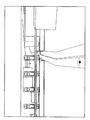
以上のような本地図表示装置の動作について、以下、図41を用いながら具体的に説明する。図41は、ユーザが本地図表示装置を携帯して電車を利用する場合における自動料金徴収センタが送信する情報を表した図である。図41において、図の右上および左下の人物および携帯用コンピュータは、ユーザ376および携帯されている本地図表示装置375である。
【0223】
図41において、本地図表示装置375を携帯したユーザ376は、左下のA駅出入り口374から電車に乗車しようとする。すると、図の下方に示されるような入り口イベント情報372が、自動料金徴収センタまたは駅出入り口付近から送信される。当該入り口イベント情報372には、フラグ情報と、料金所IDと、料金所位置情報とが含まれる。駅に入ったときには、フラグ情報としてFLG=1がセットされる。料金所IDには識別番号が付与され、A駅では1がセットされている。料金所位置情報には、緯度および経度のような座標(X1,Y1)がセットされる。本地図表示装置375は、以上のような情報を受信すると、前述のステップS615において説明したように支払履歴や料金等の所定の情報を提示する。
【0224】
次に、本地図表示装置375を携帯したユーザ376は、目的地のB駅に到着して、図41の右上のB駅出入り口373から電車を下車する。すると、図の上方に示されるような出口イベント情報371が、自動料金徴収センタまたは駅出入り口付近から送信される。当該出口イベント情報371は、入り口イベント情報372と同様であるが、駅を出るときには、フラグ情報としてFLG=0が、B駅の料金所IDには2が、料金所位置情報には座標(X2,Y2)がそれぞれセットされる。本地図表示装置375は、以上のような情報を受信すると、前述のステップS615およびサブルーチンステップS616において説明したように、所定の情報を提示するとともに、課金処理がなされる。
【0225】
以上のように、本地図表示装置は、自動料金徴収システムの端末として動作してユーザの利便を図ると共に、各種情報を、直感的に表現することで、ユーザの視認性を向上することができる。
【0226】
なお、本地図表示装置は、駅における自動料金徴収システムに用いられるように説明したが、どのような自動料金徴収システムに用いられてもよく、例えば、高速道路におけるETC(Electronic Toll Collection system)に用いられてもよい。
【0227】
さらに、本実施形態に係る地図表示装置の構成に対して、位置検出部9、経路選出部10および誘導部11をそれぞれ追加し、本地図表示装置と同様の機能を有するナビゲーション装置を構成することもできる。すなわち、本地図表示装置は、第1の実施形態に係る地図表示装置における通信部7が双方向で通信し、地図データ合成部4の動作が異なる。同様に、第2の実施形態に係るナビゲーションシステムに対して、さらに通信部7が双方向で通信し、地図データ合成部4の動作が異なるように構成すれば、本地図表示装置と同様の機能を有するナビゲーション装置を構成することができる。次に、このようなナビゲーション装置を車に搭載してETCに用いた場合の例を、第4の実施形態として説明する。
【0228】
(第4の実施形態)
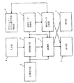
図42は、本発明の第4の実施形態に係るナビゲーション装置の構成を示すブロック図である。図42において、本ナビゲーション装置は、入力部2と、地図データ格納部3と、地図データ合成部4と、表示器5と、オブジェクトモデル提示情報格納部6と、通信部7、位置検出部9と、経路選出部10と、誘導部11とを備えている。なお、図42のナビゲーション装置は、図36の地図表示装置が備える通行券情報格納部12を備えていない。しかし、通行券の種類が同様に想定される場合などには、通行券情報格納部12を備えていてもよい。
【0229】
本ナビゲーション装置は、図33のナビゲーション装置と同様の構成部を備えるので、同様の構成部には同一の番号を付してその説明を省略する。もっとも、本ナビゲーション装置は、外部の自動料金徴収センタまたは各料金所(図示されていない)と通信部7とが双方向で通信し、誘導部11と通信部7とのデータ通信も双方向で行われる点が図33のナビゲーション装置とは異なる。また、本ナビゲーション装置は、自動料金徴収システムの端末として動作する点も異なる。ただし、基本的な動作は第3の実施形態に係る地図表示装置と同様である。以下、本ナビゲーション装置の動作について詳述する。
【0230】
図43は、自動料金徴収システムの端末として動作するナビゲーション装置の処理内容を表したフローチャートである。図43のステップS621において、入力部2から目的地や表示したい地図領域が指定され、位置検出部9から自車位置が渡されると、経路選出部10は経路探索を行い、誘導部11に経路探索結果を渡す。次に、ステップS622において、誘導部11は地図データ合成部4に地図データの合成表示を依頼する。
【0231】
ステップS623において、地図データ合成部4は、地図データ格納部3から地図データを読み込む。本ステップは、図37のステップS611に対応する。次に、ステップS624において、誘導部11は、通信部7から自動料金徴収センタまたは各料金所が送信するETC料金徴収所情報を読み込む。本ステップは、図37のステップS612に対応する。さらに、サブルーチンステップS625において、地図データ合成部4は読み込まれたETC料金徴収所情報とオブジェクトモデル提示情報格納部6にある情報を参照して料金所のオブジェクトを作成し、地図データに合成する。本ステップは、図37のサブルーチンステップS613に対応する。
【0232】
次に、ステップS626において、地図データ合成部4は、通信部7からのETC通過イベント割り込み情報があったかを判断する。具体的には、ナビゲーション装置がETCゲートを通過すると、自動料金徴収センタまたは各料金所からETC通過イベント割り込み情報が送信される。ETC通過イベント割り込み情報は、第3の実施形態において説明した駅通過イベント割り込み情報とほぼ同様の内容である。その内容については後述する。地図データ合成部4は、通信部7によって当該情報が受信されたか否かを判断する。当該情報が受信されていなければ、地図データ合成部4は、処理を終了する。もっとも、図43の処理は、典型的には一定の時間ごとに行われるので、ステップS626における判断は繰り返しなされることになる。当該情報が受信されていれば、地図データ合成部4は、ステップS627の処理へ進む。なお、本ステップは、図37のステップS614に対応する。
【0233】
ステップS627において、地図データ合成部4は、受信されたETC通過イベント割り込み情報を解析し、入口イベント情報が受信されたとき、または入口および出口イベント情報が受信されたときには、対応するオブジェクトモデル提示情報格納部6に格納されているオブジェクトモデル提示情報を実行し、所定のシンボルを表示する。典型的には、表示されている料金所のシンボル内に支払履歴や料金累計等の情報を表示する。なお、本ステップは、図37のステップS615に対応する。
【0234】
図44は、ステップS627において表示される所定のシンボルを例示した図である。図44においても、図38の場合と同様に、2つのシンボル、すなわち、料金所シンボル1011および料金情報シンボル1012が示されている。料金所シンボル1011は、典型的には、前述のETC料金所情報に対応する料金所の位置に地図と共に表示される。料金情報シンボル1012は、例えば、入り口イベント情報を受信した場合に、高速道路入り口および誘導案内経路上にあって通過が予定されている高速道路出口の情報と、その料金と、到着予定時刻と、予想所要時間とを示す。当該料金は、本ナビゲーション装置が所定のテーブルを参照して算出してもよいし、高速道路入り口および出口の情報を自動料金徴収センタ等へ送信し、そこで計算された結果を受信してもよい。
【0235】
このように、本ナビゲーション装置は、第3の実施形態に係る地図表示装置の構成に対して、位置検出部9、経路選出部10および誘導部11が追加されていることから、経路探索の結果を利用して、上述したような予測を行って、ユーザに対して事前に提示することができる。
【0236】
次に、ステップS628において、誘導部11は、入口イベント情報と出口イベント情報とが共に受信されたときには、通信部7を介して、典型的には自動料金徴収センタへ課金処理を依頼する。処理を依頼された自動料金徴収センタは、本ナビゲーション装置のユーザを判別して所定の課金処理を行う。なお、本ステップは、図37のサブルーチンステップS616に対応する。
【0237】
さらに、ステップS629において、地図データ合成部4は、実行されたオブジェクトモデル提示情報の実行が全て終了したか否かを判別する。終了していなければ、地図データ合成部4は、ステップS626の処理に戻る。終了していれば、処理は、ステップS630へ進む。なお、本ステップは、図37のステップS617に対応する。
【0238】
ステップS630において、誘導部11は、自車が目的地に到着した場合のように、誘導案内が終了したか否かを判断する。誘導案内が終了していなければ、処理はステップS622まで戻り、終了するまで繰り返される。誘導案内が終了した場合には、処理が終了する。
【0239】
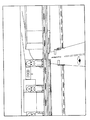
以上のような本ナビゲーション装置の動作について、以下、図45を用いながら具体的に説明する。図45は、本ナビゲーション装置がETC端末として利用される場合における自動料金徴収センタが送信する情報を表した図である。図45において、図の上下の車は、車載されている本ナビゲーション装置407である。なお、図45における自動料金徴収センタが送信する情報は、図41における自動料金徴収センタが送信する情報とほぼ同様である。
【0240】
図45において、車載されている本ナビゲーション装置407は、下のAインタ高速入り口403から有料の高速道路408に入ろうとして、ETC専用ゲートのような料金所を通過する。すると、図の下方に示されるような入り口イベント情報402が自動料金徴収センタまたは出入り口付近から送信される。典型的には、当該通信は5.8GHz帯の無線周波数、1Mbpsのデータ転送速度で行われる。当該入り口イベント情報402の内容については、図41とほぼ同様であるので、説明は省略する。車載されている本ナビゲーション装置407は、当該情報を受信すると、前述のステップS627における支払履歴や料金累計等の所定の情報を提示する。
【0241】
次に、車載されている本ナビゲーション装置407が目的地のBインタに到着して、図45の上に示されるBインター高速出口404から高速道路408を出る。すると、図の上方に示されるような出口イベント情報401が、自動料金徴収センタまたは出入り口付近から送信される。車載されている本ナビゲーション装置407は、以上のような情報を受信すると、前述のステップS627およびS628において説明したように所定の情報を提示するとともに、課金処理を受ける。
【0242】
以上のように、本ナビゲーション装置は、ETC自動料金徴収システムの端末として動作してユーザの利便を図ると共に、各種情報を直感的に表現することで、ユーザの視認性を向上することができる。
【0243】
なお、本ナビゲーション装置は、ETC自動料金徴収システムに用いられるが、どのような自動料金徴収システムに用いられてもよく、第3の実施形態において前述したような駅における自動料金徴収システムに用いられてもよい。
【0244】
また、第3の実施形態に係る地図表示装置および本実施形態に係るナビゲーション装置は、いずれも列車や高速道路などの有料区間における料金支払いに用いられるように説明した。しかし、前述のような有料区間の入り口および出口に料金所が設けられる場合に限られず、有料エリアの出入り口に料金所が設けられていてもよく、また、接近または通過することなどに対して料金の支払いが要求される所定の地点に料金所が設けられていてもよい。
【図面の簡単な説明】
【図1】本発明の第1の実施形態に係る地図表示装置の構成を示すブロック図である。
【図2】一般的なコンピュータシステムにおいて実現された第1の実施形態に係る地図表示装置の構成を示した図である。
【図3】図1の地図表示装置における地図データ合成部4の動作を示したフローチャートである。
【図4】通信部7から送られてくる情報の内容例をツリー構造を用いて表した図である。
【図5】図3のサブルーチンステップS13の詳細な処理を示すフローチャートである。
【図6】オブジェクトモデル提示情報の内容を例示して説明した図である。
【図7】図4に示されるようなその他情報に対応するオブジェクトモデル提示情報の詳細な具体例を示した図である。
【図8】図7における時空間の振る舞い方に関する情報が実行される状態を説明するための図である。
【図9】オブジェクトモデル提示情報格納部6に格納されて、交通情報に対応する関数名と関数の内容を例示した図である。
【図10】オブジェクトモデル提示情報格納部6に格納されて、緊急情報、駐車場情報および車間通信情報に対応する関数名と関数の内容を例示した図である。
【図11】VICS等から通信部7を介して送られてきた渋滞情報の構造例を示した図である。
【図12】渋滞情報提示関数が実行された場合の処理手順を示したフローチャートである。
【図13】地図データ合成部4に格納されている地図データとの関係を示す対応テーブルを例示した図である。
【図14】配置された車モデルと道路の関係を示すために、地図平面に対して垂直方向の上空から見下ろした地図の模式図である。
【図15】図14が示す地図を補間点544から補間点543の方向へ地上高から見た側面図である。
【図16】第1の実施形態に係る地図表示装置によって生成された地図画面の一例を示した図である。
【図17】地図データ合成部4の詳細な構成を示したブロック図である。
【図18】オブジェクト提示情報実行部41の詳細な構成を示したブロック図である。
【図19】サブルーチンステップS133の詳細な処理を示したフローチャートである。
【図20】2次元景観を作成する場合における表示データ合成部42の詳細な構成を示した図である。
【図21】鳥瞰図の地図画面を生成する、表示データ合成部42の詳細な構成について説明したブロック図である。
【図22】二次元の地図データに対して透視投影変換を施して鳥瞰図を作成する方法を説明した図である。
【図23】表示データ合成部42によって生成された鳥瞰図の地図画面の一例を示した図である。
【図24】鳥瞰図とは異なる3次元景観の地図画面を生成する、表示データ合成部42の詳細な構成について説明したブロック図である。
【図25】三次元地図データ作成部147の詳細な構成を示したブロック図である。
【図26】オブジェクト提示情報実行部41からは2次元のデータが入力され、地図データ格納部3からは3次元の地図データが入力されて、3次元景観の地図画面を生成する、表示データ合成部42の詳細な構成について説明したブロック図である。
【図27】オブジェクトモデル提示情報に含まれる2次元の形状情報として用意された複数の画像ファイルを例示した図である。
【図28】図26の表示データ合成部42によって作成された3次元景観の地図画面を例示した図である。
【図29】3次元景観の地図画面上に、渋滞が発生していることを示す2次元のオブジェクトが表示される場合を例示した図である。
【図30】3次元景観の地図画面上に、事故が発生していることを示す2次元のオブジェクトが表示される場合を例示した図である。
【図31】3次元景観の地図画面上に、工事中であることを示す2次元のオブジェクトが表示される場合を例示した図である。
【図32】図31から視点がさらに前方へ移動した場合において、3次元景観の地図画面上に、工事中であることを示す2次元のオブジェクトが表示される場合を例示した図である。
【図33】本発明の第2の実施形態に係るナビゲーション装置の構成を示すブロック図である。
【図34】一般的なコンピュータシステムにおいて実現された第2の実施形態に係るナビゲーション装置の構成を示した図である。
【図35】第2の実施形態に係るナビゲーション装置の基本的な処理の流れを表したフローチャートである。
【図36】本発明の第3の実施形態に係る地図表示装置の構成を示すブロック図である。
【図37】自動料金徴収システムの端末として動作する地図データ合成部4の処理内容を表したフローチャートである。
【図38】ステップS615において表示される所定のシンボルを例示した図である。
【図39】図37のサブルーチンステップS616における処理の詳細を示したフローチャートである。
【図40】通行券情報格納部12に格納されている通行券情報を例示した図である。
【図41】ユーザが本地図表示装置を携帯して電車を利用する場合における自動料金徴収センタが送信する情報を表した図である。
【図42】本発明の第4の実施形態に係るナビゲーション装置の構成を示すブロック図である。
【図43】自動料金徴収システムの端末として動作するナビゲーション装置の処理内容を表したフローチャートである。
【図44】図43のステップS627において表示される所定のシンボルを例示した図である。
【図45】本ナビゲーション装置がETC端末として利用される場合における自動料金徴収センタが送信する情報を表した図である。
【図46】従来の地図表示装置の構成を示すブロック図である。
【図47】従来のナビゲーション装置の構成を示すブロック図である。
【符号の説明】
2 入力部
3 地図データ格納部
4 地図データ合成部
5 表示器
6 オブジェクトモデル提示情報格納部
7 通信部
9 位置検出部
10 経路選出部
11 誘導部
41 オブジェクト提示情報実行部
42 表示データ合成部
141 鳥瞰図データ変形部
142 三次元オブジェクト作成部
143 三次元データ合成部
144 二次元/三次元座標変換部
145 二次元オブジェクト作成部
146 二次元データ合成部
147 三次元地図データ作成部
332 CPU
333 ROM
334 RAM
335 出力部
336 入力部
338 通信部
342 CPU
343 ROM
344 RAM
345 出力部
346 入力部
348 通信部
349 位置検出部
411 オブジェクト提示情報制御部
412 解釈実行部
1471 高さ・幅情報付与部
1472 3次元ポリゴン作成部[0001]
BACKGROUND OF THE INVENTION
The present invention relates to a map display device and a navigation device, and more specifically, analyzes communication information including information for specifying a toll gate to be passed, which is input from the outside via a communication unit, and The present invention relates to a map display device and a navigation device that convert the object into a composite object, display it in combination, and perform communication for charging processing in a predetermined case.
[0002]
[Prior art]
Conventional map display devices and navigation devices display traffic information and road regulation information from existing information communication systems or information flowing from the Internet on a screen different from the map display screen. That is, the conventional map display device and navigation device do not convert these information into objects in the map and display them in combination.
[0003]
Here, as an existing information communication system, road information such as traffic congestion information and accident information called VICS (Vehicle Information and Communication System) is real-time using FM multiplex broadcasting, radio wave beacon, optical beacon, and the like. There is an information communication system that transmits information.
[0004]
The traffic jam information transmitted in such an existing information communication system specifically includes a link number of a road in which traffic is jammed. Therefore, the conventional navigation apparatus generally displays such traffic information on a simple map schematically represented and displays it on a screen different from the map screen for navigation.
[0005]
Also, even when the traffic information is displayed on the same screen, the conventional navigation device does not convert the traffic information into an object in the map and displays it in a composite manner. Only the corresponding road color is changed and displayed. The reason why the conventional navigation device changes the color and displays the object is that the object generated in the existing system is fixed. Therefore, in order for the conventional navigation device to display the traffic jam information without generating a new object, there is only a method for changing the color.
[0006]
Some recent navigation devices have an Internet browser added to display information from the Internet on a screen different from the map screen. Such a device connects a car or a person isolated from external information to the outside via the Internet by a built-in communication system.
[0007]
The configuration and operation of the conventional map display device and navigation device as described above will be described with reference to FIGS. 46 and 47. FIG. FIG. 46 is a block diagram showing a configuration of a conventional map display device. 46, the conventional map display device includes an
[0008]
The
[0009]
The map
[0010]
The
[0011]
The map
[0012]
Next, FIG. 47 is a block diagram showing a configuration of a conventional navigation apparatus as described above. Here, it is assumed that this navigation device is mounted on a vehicle. 47, the conventional navigation apparatus includes an
[0013]
The
[0014]
The map
[0015]
The
[0016]
The
[0017]
The
[0018]
The
[0019]
According to such a map display device and navigation device, the user can easily obtain the latest information from the outside, for example, traffic information and parking lot information. Therefore, such a conventional map display device or navigation device can make the user ascertain as much information as possible about the destination.
[0020]
[Problems to be solved by the invention]
However, in the conventional navigation apparatus, the Internet browser is basically displayed on a screen different from the map screen. Similarly, traffic information by VICS is generally displayed on a simple map on a separate screen. Therefore, it is necessary for the user to move the line of sight to compare and refer to the necessary information and the displayed information. However, when the user performs such association, it is preferable to temporarily stop the vehicle. Therefore, there is a problem that the advantages of the navigation device as described above cannot be fully exhibited while the vehicle is traveling. This is the same whether the navigation device is mounted on a moving body other than a vehicle or carried by a pedestrian.
[0021]
However, in the conventional navigation device, it is extremely difficult to display various information in a synthesized manner without generating a new object on the navigation screen, except for the case where the display color is changed and displayed as described above. It is.
[0022]
Here, all data including images and 3D polygon data necessary to generate a new object are received and synthesized on the map screen via the communication means incorporating the map display device and the navigation device. A configuration to display is also conceivable. However, according to such a configuration of the map display device and the navigation device, the amount of information to be transmitted / received increases, which is not economical.
[0023]
On the other hand, a configuration in which the map display device and the navigation device hold data for generating all objects corresponding to various information in advance is also conceivable. However, according to such a configuration of the map display device and the navigation device, there is a problem that the capacity of the storage medium provided for storing the object becomes very large, which is also not economical.
[0024]
Therefore, the object of the present invention is to synthesize on a map communication information including regulation information and traffic jam information that change in real time, or various information flowing from the Internet and information for specifying a tollgate to pass. It is possible to provide a map display device and a navigation device that can more intuitively grasp information without moving the line of sight, and perform communication for billing processing in a predetermined case.
[0025]
Another object of the present invention is to provide the above map display device and navigation device that can reduce the capacity of a storage medium for storing objects while the amount of information to be transmitted and received is small. .
[0026]
[Means for Solving the Problems and Effects of the Invention]
A first aspect of the present invention is a map display device for composing and displaying communication information transmitted from the outside of the device as an object having a predetermined shape on a map and performing communication for charging processing in a predetermined case. ,
An input unit for inputting an instruction from the user;
A map data storage unit for storing map information in advance;
An object model presentation information storage unit for storing object model presentation information for presenting an object on a map;
A communication unit that receives communication information including information for specifying a tollgate to pass, and transmits charging information for charging processing in a predetermined case; and
A map data synthesizing unit that interprets corresponding object model presentation information input from the communication information and object model presentation information storage unit, generates an object, synthesizes it on a map, and generates accounting information in a predetermined case; ,
A display unit that displays a map screen synthesized by the map data synthesis unit to the user.
[0027]
As described above, according to the first aspect, the object is based on the map data stored in the map data storage unit, the information sent from the communication unit, and the information stored in the object model presentation information storage unit. Can be combined and presented in the map data space, and billing processing can be performed, so the regulation information and traffic jam information that changes in real time or various information that flows from the Internet can be more intuitive without moving the line of sight In this way, the visibility of the user can be improved, and the user can be operated by operating as a terminal of the automatic fee collection system.
[0028]
Furthermore, pre-registered in the storage medium is object model presentation information for which the presentation conditions and presentation contents are to be changed in real time. If conditions are established at the time of execution, objects can be created and deleted on the spot. it can. Therefore, not only the capacity to be stored is small, but also the capacity to be stored can be reduced when the object model presentation condition is updated or additionally deleted via the communication unit. Therefore, an economical map display device can be provided.
[0029]
The second invention is an invention subordinate to the first invention,
Object model presentation information
Information about the shape of the object,
Information about the spatio-temporal behavior of the object.
[0030]
As described above, according to the second invention, the information stored in the object model presentation information storage unit is composed of a set of information related to the shape of the object and information related to the behavior of the space-time. It is possible to easily manage information as in the case of exchanging, or in the case of exchanging only a part of the information related to the shape information or the behavior of time and space.
[0031]
The third invention is an invention subordinate to the second invention,
Information on the spatio-temporal behavior of objects is described using an object-oriented interpreter language that can be executed without compilation.
[0032]
As described above, according to the third invention, since the information stored in the object model presentation information storage unit can be described by a script that can be executed without compiling, the object model presentation information independent of the map display device is used. be able to. Therefore, the operation on the server side that provides the object model presentation information can be facilitated. Further, for example, by using a standard script language such as JAVA, the object model presentation information can be captured widely via the network, so that the distribution and reusability of the object model presentation information can be improved. .
[0033]
The fourth invention is an invention subordinate to the second invention,
The information regarding the spatio-temporal behavior of the object includes an execution condition and an execution function.
[0034]
As described above, according to the fourth invention, it is not necessary to fix the execution condition. Therefore, it is not necessary for the object to react the same as the user's input or information input from the communication unit every time, and it is possible to provide unexpected and flexible presentation contents.
[0035]
The fifth invention is an invention subordinate to the first invention,
The map data synthesizer
An object presentation information execution unit that interprets and executes corresponding object model presentation information input from the communication information and object model presentation information storage unit;
An object creation unit that generates an object by inputting an execution result in the object presentation information execution unit;
And a data composition unit for composing the object on the map.
[0036]
As described above, according to the fifth invention, since a two-dimensional or three-dimensional object can be generated and synthesized on a two-dimensional or three-dimensional map, various information can be displayed without moving the line of sight. By expressing it more intuitively, the visibility of the user can be improved.
[0037]
The sixth invention is an invention subordinate to the fifth invention,
The map data synthesis unit further includes a 3D map creation unit that creates a 3D map based on the map information of the 2D data input from the map data storage unit,
The data synthesis unit synthesizes the object on the map created by the 3D map creation unit.
[0038]
As described above, according to the sixth invention, since a two-dimensional or three-dimensional object can be generated and synthesized on a three-dimensional map, various information can be more intuitive without moving the line of sight. It is possible to improve the visibility of the user by expressing the above. In addition, since the three-dimensional map is created based on the map information of the two-dimensional data, the capacity of the storage medium for storing the map in the map data storage unit can be reduced.
[0039]
The seventh invention is an invention subordinate to the fifth invention,
The map data synthesis unit further includes a 2D / 3D coordinate conversion unit that converts the 2D object generated by the object creation unit into a 3D object,
The data synthesizing unit synthesizes the three-dimensional object converted by the two-dimensional / three-dimensional coordinate conversion unit on a map.
[0040]
As described above, according to the seventh invention, since a two-dimensional object can be generated and synthesized on a two-dimensional or three-dimensional map, various information can be more intuitive without moving the line of sight. It is possible to improve the visibility of the user by expressing the above. Further, since the three-dimensional object is created based on the object model presentation information of the two-dimensional data, the capacity of the storage medium for storing the object model presentation information in the object model presentation information storage unit can be reduced.
[0041]
The eighth invention is an invention subordinate to the first invention,
The map data compositing unit generates billing information by referring to the communication information about the toll booths provided at the entrance and exit in a predetermined toll section, generates an object including the toll amount in the toll section and composes it on the map It is characterized by doing.
[0042]
The ninth invention is an invention subordinate to the first invention,
Further comprising a pass ticket information storage unit for storing pass ticket information corresponding to a pass ticket used for paying a fee in a toll section;
The map data synthesizing unit creates the pass ticket information stored in the pass ticket information storage unit when purchasing the pass ticket, and changes the pass ticket information in a predetermined case.
[0043]
A tenth invention is an invention subordinate to the ninth invention,
The pass ticket information includes information about the expiry date of the pass ticket,
The map data synthesizing unit refers to information related to the expiration date of the pass ticket, creates a warning message in a predetermined case, and displays the warning message on the display unit.
[0044]
As described above, according to the eighth to tenth aspects of the present invention, the map display device operates as a terminal of the automatic fee collection system for the convenience of the user and expresses various information such as fees intuitively. By doing so, the visibility of the user can be improved.
[0045]
In an eleventh aspect, communication information transmitted from the outside of the apparatus is synthesized and displayed as an object having a predetermined shape on a map, and guidance to a destination is provided. A navigation device for communication,
An input unit for inputting an instruction from the user;
A position detector for detecting the current position;
A map data storage unit for storing map information in advance;
An object model presentation information storage unit that stores in advance object model presentation information for presenting an object on a map;
A route selection unit that selects a route to the destination based on the instruction input from the input unit, the current position detected by the position detection unit, and the map information stored in the map data storage unit;
A communication unit that receives communication information including information for specifying a tollgate to pass, and transmits charging information for charging processing in a predetermined case;
A map data composition unit that interprets corresponding object model presentation information input from the communication information and object model presentation information storage unit, generates an object, and synthesizes it on a map;
The communication information received by the communication unit, the route selected by the route selection unit, the current position detected by the position detection unit, and the map information from the map data storage unit are input, and guidance to the destination A guidance unit that generates a guidance, outputs a map screen synthesized by the map data synthesis unit, and generates billing information in a predetermined case;
A display unit that displays a map screen input from the guide unit to the user.
[0046]
A twelfth invention is an invention subordinate to the eleventh invention,
Object model presentation information
Information about the shape of the object,
Information about the spatio-temporal behavior of the object.
[0047]
A thirteenth invention is an invention subordinate to the twelfth invention,
Information on the spatio-temporal behavior of objects is described using an object-oriented interpreter language that can be executed without compilation.
[0048]
A fourteenth invention is an invention subordinate to the twelfth invention,
The information regarding the spatio-temporal behavior of the object includes an execution condition and an execution function.
[0049]
The fifteenth invention is an invention subordinate to the eleventh invention,
The map data synthesizer
An object presentation information execution unit that interprets and executes corresponding object model presentation information input from the communication information and object model presentation information storage unit;
An object creation unit that generates an object by inputting an execution result in the object presentation information execution unit;
And a data composition unit for composing the object on the map.
[0050]
A sixteenth invention is an invention subordinate to the fifteenth invention,
The map data synthesis unit further includes a 3D map creation unit that creates a 3D map based on the map information of the 2D data input from the map data storage unit,
The data synthesis unit synthesizes the object on the map created by the 3D map creation unit.
[0051]
The seventeenth invention is an invention subordinate to the fifteenth invention,
The map data synthesis unit further includes a 2D / 3D coordinate conversion unit that converts the 2D object generated by the object creation unit into a 3D object,
The data synthesizing unit synthesizes the three-dimensional object converted by the two-dimensional / three-dimensional coordinate conversion unit on a map.
[0052]
An eighteenth invention is an invention subordinate to the eleventh invention,
The guide unit generates billing information with reference to communication information related to the toll gate provided at the entrance and exit in a predetermined toll section,
The map data composition unit generates an object including a charge amount in a toll section and composes it on a map.
[0053]
The nineteenth invention is an invention subordinate to the eleventh invention,
A travel ticket information storage unit for storing the pass ticket information corresponding to the pass ticket used for the fee payment in a predetermined toll section,
The guide unit creates the pass ticket information stored in the pass ticket information storage unit when purchasing the pass ticket, and changes the pass ticket information in a predetermined case.
[0054]
The twentieth invention is an invention subordinate to the nineteenth invention,
The pass ticket information includes information about the expiry date of the pass ticket,
The map data synthesizing unit refers to information related to the expiration date of the pass ticket, creates a warning message in a predetermined case, and displays the warning message on the display unit.
[0055]
As described above, according to the eleventh and twentieth inventions, it is possible to provide a navigation device having the same effects as the map display devices according to the first to tenth inventions described above.
[0056]
A twenty-first invention is a map display method for communicatively displaying communication information transmitted from the outside as an object having a predetermined shape on a map and performing communication for charging processing in a predetermined case,
An input step in which an instruction from the user is input;
A communication step of receiving communication information including information for specifying a toll booth to pass, and transmitting charging information for charging processing in a predetermined case;
An object model presentation information for presenting communication information and a corresponding object on a map to generate an object, synthesize it on the map, and a map data synthesis step for generating billing information in a predetermined case;
A display step of displaying the map screen synthesized in the map data synthesis step to the user.
[0057]
The twenty-second invention is an invention subordinate to the twenty-first invention,
The map data synthesis step
An object presentation information execution step for interpreting and executing communication information and corresponding object model presentation information;
An object creation step for generating an object from the execution result in the object presentation information execution step;
And a data synthesis step for synthesizing the object on the map.
[0058]
A twenty-third invention is an invention subordinate to the twenty-second invention,
The map data synthesis step further includes a 3D map creation step of creating a 3D map based on the map information of the 2D data,
The data synthesis step is characterized in that the object is synthesized on the map created in the three-dimensional map creation step.
[0059]
A twenty-fourth invention is an invention subordinate to the twenty-second invention,
The map data synthesis step further includes a 2D / 3D coordinate conversion step of converting the 2D object created in the object creation step into a 3D object,
The data composition step is characterized in that the three-dimensional object converted in the two-dimensional / three-dimensional coordinate conversion step is synthesized on a map.
[0060]
A twenty-fifth aspect of the invention is a navigation method for communicating and displaying communication information transmitted from the outside as an object having a predetermined shape on a map and performing communication for billing processing in a predetermined case,
An input step in which an instruction from the user is input;
A communication step of receiving communication information including information for specifying a toll booth to pass, and transmitting charging information for charging processing in a predetermined case;
A position detection step for detecting the current position;
A map data synthesis step of generating an object by interpreting object model presentation information for presenting communication information and a corresponding object on a map, and synthesizing the object on a map;
A route selection step of selecting a route to the destination based on the instruction input in the input step, the current position detected in the position detection step, and the map information;
Based on the communication information received in the communication step, the route selected in the route selection step, the current position detected in the position detection step, and the map information, a guidance guide to the destination is generated, and a map Outputting a map screen synthesized in the data synthesis step, and generating a billing information in a predetermined case; and
A display step of displaying the map screen output in the guidance step to the user.
[0061]
According to a twenty-sixth aspect of the present invention, there is provided a map display device for communicatively displaying communication information transmitted from the outside as an object having a predetermined shape on a map and performing communication for charging processing in a predetermined case.
Object presentation information execution step for interpreting and executing communication information including information for specifying a toll booth to pass through and object model presentation information for presenting an object on a map;
An object creation step for generating an object from the execution result in the object presentation information execution step;
A data synthesis step to synthesize the object on the map;
It is a computer-readable recording medium recording a program for executing a billing process information creating step for creating billing information for billing processing in a predetermined case.
[0062]
According to a twenty-seventh aspect of the present invention, there is provided a navigation apparatus for compositing and displaying communication information transmitted from the outside as an object having a predetermined shape on a map and performing communication for charging processing in a predetermined case.
Map data synthesis step for generating communication objects including information for identifying tollgates to pass and object model presentation information for presenting corresponding objects on the map, and generating objects on the map When,
A route selection step of selecting a route to the destination based on the instruction input from the user, the current position, and the map information;
Based on the communication information, the route selected in the route selection step, the current position, and the map information, a guidance guide to the destination is generated, and the map screen synthesized in the map data synthesis step is output, The computer-readable recording medium stores a program for executing a guidance step for generating billing information for billing processing in a predetermined case.
[0063]
According to a twenty-eighth aspect of the present invention, there is provided a map display device for communicatively displaying communication information transmitted from the outside as an object having a predetermined shape on a map and performing communication for charging processing in a predetermined case.
An object presentation information execution step for interpreting and executing object model presentation information for presenting communication information and objects on a map;
An object creation step for generating an object from the execution result in the object presentation information execution step;
A data synthesis step to synthesize the object on the map;
A computer program for executing a billing process information creation step for creating billing information for billing processing in a predetermined case.
[0064]
According to a twenty-ninth aspect of the present invention, there is provided a navigation apparatus for compositing and displaying communication information transmitted from the outside as an object having a predetermined shape on a map and performing communication for billing processing in a predetermined case.
Map data synthesis step for generating communication objects including information for identifying tollgates to pass and object model presentation information for presenting corresponding objects on the map, and generating objects on the map When,
A route selection step of selecting a route to the destination based on the instruction input from the user, the current position, and the map information;
Based on the communication information, the route selected in the route selection step, the current position, and the map information, a guidance guide to the destination is generated, and the map screen synthesized in the map data synthesis step is output, A computer program for executing a guidance step for generating billing information for billing processing in a predetermined case.
[0065]
DETAILED DESCRIPTION OF THE INVENTION
(Description of the basic concept of the present invention)
Before describing each embodiment of the present invention in detail, the basic concept will be described in order to facilitate understanding of the present invention.
[0066]
The device according to each embodiment of the present invention receives information from the outside, converts it into an object having the same dimension as a map space (for example, a three-dimensional map space) displayed on the device, and further maps the map space. Is displayed in a composite. As a result, the user can more intuitively understand regulation information and traffic jam information that change in real time, or various types of information flowing from the Internet without moving his / her line of sight. Therefore, the apparatus according to the embodiment of the present invention can improve the visibility of information for the user and can improve the convenience for the user.
[0067]
Further, if the map displayed on the apparatus is three-dimensional, it gives the user a more realistic sensation, but the amount of information increases when transmitting the polygon data of the corresponding three-dimensional object as it is. Further, in such a case, since the terminal side does not have a function of synthesizing data, the information presentation method cannot be customized according to the situation. On the other hand, the apparatus according to each embodiment of the present invention can receive compressed information and provide a flexible user interface according to the current situation, user preference, and the like.
[0068]
Each device according to the following embodiments is described as being mounted on a vehicle or carried by a pedestrian, but any device may be mounted on a moving body other than the vehicle, It may be an independent device that is carried around.
[0069]
In addition, the above description of the basic concept should be used only to facilitate understanding of the present invention, and should not be used to unduly narrow the scope of rights of the present invention. Is pointed out in advance.
[0070]
(First embodiment)
FIG. 1 is a block diagram showing the configuration of the map display device according to the first embodiment of the present invention. In FIG. 1, the map display device includes an
[0071]
The
[0072]
The map
[0073]
The
[0074]
Similar to the map
[0075]
The map
[0076]
The
[0077]
The configuration of the map display device in FIG. 1 as described above can be realized in a general computer system. FIG. 2 is a diagram showing a configuration of a map display device realized in a general computer system.
[0078]
In FIG. 2, the map display apparatus includes a
[0079]
In FIG. 2, the
[0080]
Further, typically, the map
[0081]
As described above, the map display device according to the first embodiment shown in FIG. 1 is different from the conventional map display device in FIG. 46 in that the object model presentation
[0082]
FIG. 3 is a flowchart showing the operation of the map
[0083]
First, in step S <b> 11 of FIG. 3, the map
[0084]
Next, in step S <b> 12, the map
[0085]
Such information sent from the
[0086]
First, in FIG. 4, the traffic information includes traffic jam information, accident information, under-construction information, and freezing information. The information contents will be described below. The traffic jam information has, for example, a data structure including a traffic jam information ID and link data. Here, the link refers to a unit for expressing a position corresponding to a road in a predetermined section, such as an intercept obtained by dividing a road according to directions from the intersection to the intersection. Typically, the link data includes link information, From information, To information, and lane information. Here, the traffic jam information ID is an information identification number for identifying that the following link data is traffic jam information. The link information is a link number of a map corresponding to a road where a traffic jam occurs. The From information indicates the start position of an interpolation point number or the like in the link where the traffic jam occurs. The To information indicates an end position such as an interpolation point number in the link where the traffic jam occurs. The lane information is information such as a lane number where a traffic jam occurs. Note that the traffic jam information may include a plurality of link data.
[0087]
The accident information has a data structure including an accident information ID and link data, for example. Typically, the link data includes link information, latitude / longitude, and lane information. Here, the accident information ID is an information identification number for identifying that the following link data is accident information. The link information is a link number of a map corresponding to the road where the accident occurs. The latitude and longitude indicate the latitude and longitude in the link of the place where the accident has occurred. The lane information is information such as the lane number where an accident has occurred.
[0088]
The under-construction information has a data structure including, for example, a construction information ID and link data. Typically, the link data includes link information, From information, To information, and lane information. Here, the construction information ID is an information identification number for identifying that the following link data is construction information. The link information is a link number of a map corresponding to a road on which construction is being performed. From information indicates the start position of an interpolation point number or the like in a link where construction is being performed. The To information indicates an end position such as an interpolation point number in a link where construction is being performed. The lane information is information such as the lane number being constructed. The under-construction information may include a plurality of link data.
[0089]
The freeze information has a data structure including, for example, a freeze information ID and link data. Typically, link data includes link information, From information, and To information. Here, the freeze information ID is an information identification number for identifying that the subsequent link data is freeze information. The link information is a link number of a map corresponding to a road where freezing occurs. From information indicates the starting position of an interpolation point number or the like in a link where freezing occurs. The To information indicates an end position such as an interpolation point number in the link where freezing occurs. The freezing information may include a plurality of link data.
[0090]
Next, the emergency information includes ambulance information, police car information, and fire engine information. The information contents will be described below. The ambulance information has a data structure including, for example, an emergency information ID and link data. Typically, the link data includes current location information, To information, and route information. The emergency information ID is an information identification number for identifying that the following link data is ambulance information. The current location information is information on the current position of the ambulance. The To information is information for indicating where the ambulance is heading, such as the location where the emergency patient is generated, the location of the hospital, or the facility number thereof. The route information is route information predicted that an ambulance will pass. The route information may be calculated by performing a route search based on the current location information and To information.
[0091]
The police car information has, for example, a data structure including a police car information ID and link data. Typically, the link data includes current location information, To information, and route information. The police car information ID is an information identification number for identifying that the following link data is police car information. The current location information is information on the current position of the police car. The To information is information for indicating where the police car is heading, and is the place where the incident occurred, the location of the police, or the facility number thereof. The route information is route information predicted that the police car will pass. The route information may be calculated by performing a route search based on the current location information and To information.
[0092]
The fire engine information has, for example, a data structure including a fire information ID and link data. Typically, the link data includes current location information, To information, and route information. The fire fighting information ID is an information identification number for identifying that the following link data is fire truck information. The current location information is information on the current position of the fire engine. The To information is information for indicating where the fire engine is heading, and is a place where a fire has occurred, a place of a hospital, or a facility number thereof. The route information is route information predicted that the fire engine will pass. The route information may be calculated by performing a route search based on the current location information and To information.
[0093]
The parking lot information includes parking lot availability information and the like. The parking lot availability information has a data structure including, for example, a parking lot information ID and link data. Typically, the link data includes position information, a parking lot ID, and vacancy information. The parking lot information ID is an information identification number for identifying that the following link data is parking lot information. The position information is information on the position of the parking lot. The parking lot ID is a facility number corresponding to the parking lot. The vacancy information is information indicating the vacancy state of the parking lot.
[0094]
Further, the inter-vehicle communication information includes inter-vehicle distance information and the like. The inter-vehicle distance information has a data structure including, for example, an inter-vehicle distance information ID and link data. Typically, the link data includes a front distance, a vehicle type, a rear distance, and a vehicle type. The inter-vehicle distance information ID is an information identification number for identifying that the following link data is inter-vehicle distance information. The front distance and the vehicle type indicate the inter-vehicle distance from the vehicle in front and the vehicle type. The rear distance and the vehicle type indicate the inter-vehicle distance from the vehicle behind and the vehicle type.
[0095]
Finally, the other information includes landmark information, sports information, and gambling information. The information contents will be described below. The landmark information has a data structure including, for example, a facility ID and link data. Note that the landmark information here is different from the general landmark information described above, and includes provision information related to the landmark, such as store type information and advertisement information. Specifically, the advertisement information includes service contents at corresponding stores such as bargains and events, and text or image information for advertising the stores and the products themselves. The link data included in the landmark information typically includes adjacent link information, latitude / longitude, and provision information. The facility ID is an information identification number for identifying that the following link data is information regarding a facility such as a landmark. The adjacent link information is link information adjacent to the nearest neighbor. The latitude / longitude is a latitude / longitude serving as a reference for arrangement of the facility. The provision information includes the provision information as described above regarding the landmark.
[0096]
The sports information has a data structure including, for example, a facility ID and link data. Typically, the link data includes adjacent link information, latitude / longitude, and provision information. The facility ID is an information identification number for identifying that the subsequent link data is information regarding the facility. The adjacent link information is link information adjacent to the nearest neighbor. The latitude / longitude is a latitude / longitude serving as a reference for arrangement of the facility. Provision information is provision information, such as a game result regarding sports.
[0097]
The gambling information has a data structure including, for example, a facility ID and link data. Typically, the link data includes adjacent link information, latitude / longitude, and provision information. The facility ID is an information identification number for identifying that the subsequent link data is information regarding the facility. The adjacent link information is link information adjacent to the nearest neighbor. The latitude / longitude is a latitude / longitude serving as a reference for arrangement of the facility. The provided information is provided information such as a result related to gambling.
[0098]
Next, in subroutine step S13 of FIG. 3, the map
[0099]
FIG. 5 is a flowchart showing detailed processing of subroutine step S13 of FIG. In step S131 of FIG. 5, the map
[0100]
In step S <b> 132, the map
[0101]
Furthermore, the map
[0102]
Here, the contents of the object model presentation information will be described. FIG. 6 is a diagram illustrating the contents of the object model presentation information as an example. As shown in FIG. 6, the object model presentation information can typically be divided into information related to the shape and information related to the behavior of the space-time.
[0103]
The information on the shape is directly expressed by using, for example, polygon information for expressing the shape and a description for specifying the texture to be attached to the polygon. Alternatively, the information on the shape is indirectly expressed using a description specifying a function and a parameter.
[0104]
Next, the information regarding the behavior of the spatio-temporal is expressed, for example, such that a predetermined process is executed if a predetermined condition is met. If expressed in this way, there is no need to fix execution conditions. Therefore, it is not necessary for the object to react the same as the user's input or the information input from the
[0105]
Typically, as information related to the behavior of the space-time in FIG. 6, a method executed when a corresponding object is created is described in CREATE in the figure. In addition, as information on how the spacetime behaves, CAR_NEAR in the figure describes a method that is executed when the vehicle approaches within a predetermined distance of the object.
[0106]
Further, a specific example of the object model presentation information as described above will be described with reference to FIG. FIG. 7 is a diagram showing a specific example of object model presentation information corresponding to other information as shown in FIG.
[0107]
In FIG. 7, the object
[0108]
The
[0109]
In the
[0110]
FIG. 8 is a diagram for explaining a state in which information relating to the behavior of space-time in FIG. 7 is executed. In FIG. 8, Road Objects represents a road on the map, and a rectangular parallelepiped at the top of the figure represents an object drawn on the map. Here, it is assumed that the vehicle is traveling along a route Route represented by a thick line in the figure. First, when the position of the car is in
[0111]
Next, the case where the information related to the behavior of the space-time is expressed in a format describing the function name and the function content will be described with reference to FIGS. FIG. 9 is a diagram exemplifying function names and function contents stored in the object model presentation
[0112]
In FIG. 9, for example, when traffic jam information is sent from the VICS or the like via the
[0113]
Note that the above processing is similarly performed on other communication information, and individual functions stored in the object model presentation
[0114]
Next, a specific processing example when the above-described traffic jam information presentation function is executed will be further described in detail. First, the traffic jam information read from the
[0115]
FIG. 11 is a diagram illustrating a structure example of traffic jam information sent from the VICS or the like via the
[0116]
The traffic
[0117]
Next, a processing procedure when the traffic jam information presentation function is executed will be described. FIG. 12 is a flowchart showing a processing procedure when the traffic jam information presentation function is executed. When the traffic jam information presentation function is executed in step S101 of FIG. 12, first, the map
[0118]
FIG. 13 is a diagram illustrating a correspondence table showing the relationship with the map data stored in the map
[0119]
Here, the number of roads is stored in the map
[0120]
The set of the sequence number, start spine point number, and end spine point number shown here varies depending on the data structure of the map data, but may uniquely indicate any line element side in the map data. Any data can be used as long as the data can be used.
[0121]
Next, in step S102 of FIG. 12, the map
[0122]
In step S103, the map
[0123]
In step S104, the map
[0124]
Next, in step S104, the map
[0125]
Further, in step S104, the map
[0126]
When the processing related to a certain road is completed as described above, in step S105, the map
[0127]
When all the processes are completed, in step S108, the map
[0128]
FIG. 14 is a schematic diagram of a map looking down from above in the direction perpendicular to the map plane in order to show the relationship between the car model and the road arranged as described above. In FIG. 14, a
[0129]
Referring to FIGS. 14 and 15, the
[0130]
The processing of the congestion information presentation function as described above can be performed in the same procedure with respect to the display of lane restriction information during construction. Of course, the traffic jam information ID in the traffic jam information described above is replaced with the construction-in-progress information ID, and the model arranged on the road is replaced with a model such as a signboard or a doll indicating the construction in progress from the car. Thus, the processing of the functions shown in FIGS. 9 and 10 can be performed in the same manner.
[0131]
When the process of subroutine step S133 in FIG. 5 is completed as described above, next, in step S134, the map
[0132]
FIG. 16 is a diagram showing a display example of a map screen generated through the above processing. In FIG. 16, on a three-dimensional landscape including a group of buildings, a vehicle polygon indicating the position of a police car, a traffic jam billboard indicating traffic jam, and an animation graphic indicating that construction is underway are arranged. Therefore, the user can intuitively grasp various information without moving the line of sight.
[0133]
Furthermore, as a premise for explaining the detailed processing of the map
[0134]
FIG. 17 is a block diagram showing a detailed configuration of the map
[0135]
The object presentation
[0136]
Next, a detailed configuration of the object presentation
[0137]
The object presentation
[0138]
Based on the above, detailed processing of the map
[0139]
In step S91 of FIG. 19, the object presentation
[0140]
When an interrupt event is detected, in step S92, the object presentation
[0141]
In step S <b> 94 (update event), the object presentation
[0142]
In step S95 (presentation condition firing event), the object presentation
[0143]
In step S96 (creation event), the object presentation
[0144]
Next, in step S99, the object presentation
[0145]
In step S98 (attribute change event), the object presentation
[0146]
Further, how the display
[0147]
The two-dimensional
[0148]
Next, the case where the map screen produced | generated in the display data synthetic |
[0149]
FIG. 21 shows a display
[0150]
In FIG. 21, the display
[0151]
The bird's eye view
[0152]
FIG. 22 is a diagram illustrating a method of creating a bird's eye view by performing perspective projection conversion on two-dimensional map data. In FIG. 22, V (Vx, Vy, Vz) represents viewpoint coordinates. S (Sx, Sy) represents the coordinates of the bird's eye view image on the monitor. M (Mx, My, Mz) represents coordinates on the two-dimensional map. Since map data is two-dimensional data, Mz is 0. E (Ex, Ey, Ez) represents the relative position of the point M seen in the viewpoint coordinate system. θ represents the look-down angle of the line of sight, and φ represents the direction angle of the line of sight. DS represents the theoretical distance between the viewpoint and the screen.
[0153]
Here, if the coordinates V (Vx, Vy, Vz) of the viewpoint, the look-down angle θ of the line of sight, and the direction angle φ of the line of sight are determined, the coordinates M (Mx, My, Mz) on the two-dimensional map are determined. Thus, the coordinates S (Sx, Sy) of the bird's eye view image can be obtained. The calculation formula can be expressed as the following formula (1).
[Expression 1]
The bird's eye view
[0155]
The three-dimensional
[0156]
The three-dimensional
[0157]
In FIG. 23, on the map displayed in the form of a bird's-eye view, a three-dimensional object indicating that construction is in progress and an object indicating that the parking lot is full are arranged. In FIG. 23, even if these objects look like two-dimensional objects, they represent three-dimensional objects whose shape changes as the viewpoint changes.
[0158]
Next, three-dimensional data is input from the object presentation
[0159]
In FIG. 24, three-dimensional data is input from the object presentation
[0160]
In FIG. 24, the display
[0161]
In FIG. 24, the three-dimensional
[0162]
FIG. 25 is a block diagram showing a detailed configuration of the 3D map
[0163]
The height / width
[0164]
A 3D
[0165]
Next, the display
[0166]
FIG. 26 shows display data composition in which two-dimensional data is input from the object presentation
[0167]
In FIG. 26, the display
[0168]
In FIG. 26, a two-dimensional
[0169]
Specifically, as described above, a plurality of image files are prepared as two-dimensional shape information included in the object model presentation information. FIG. 27 is a diagram illustrating a plurality of image files prepared as two-dimensional shape information included in the object model presentation information. In FIG. 27, each of the plurality of images is divided into an accident image, a construction image, and a traffic jam image. These types of images correspond to each object model presentation information. Each type of image is further divided into a long-distance use, a medium-distance use, and a short-distance use.
[0170]
First, the two-dimensional
[0171]
The two-dimensional / three-dimensional coordinate
[0172]
The three-dimensional
[0173]
Further, according to the above configuration, the two-dimensional object created by the two-dimensional
[0174]
FIG. 28 is a diagram illustrating a map screen of a three-dimensional landscape created by the display
[0175]
Finally, the display
[0176]
The display
[0177]
That is, the display
[0178]
As described above, when the display
[0179]
Furthermore, when the display
[0180]
FIG. 29 is a diagram exemplifying a case where a two-dimensional object indicating that a traffic jam has occurred is displayed on the map screen of the three-dimensional landscape. As shown in FIG. 29, by displaying a plurality of objects indicating traffic jams, it is possible to intuitively understand that the traveling direction is traffic jams.
[0181]
FIG. 30 is a diagram illustrating a case where a two-dimensional object indicating that an accident has occurred is displayed on the map screen of the three-dimensional landscape. As shown in FIG. 30, by displaying objects indicating a plurality of accidents, it is possible to intuitively understand that an accident has occurred in the traveling direction.
[0182]
Furthermore, for example, when the user is traveling on a road and there is a road under construction in front of the user, an object indicating that the construction is underway is displayed on the map screen of the three-dimensional landscape. Can intuitively grasp the road under construction. Also, typically, when the viewpoint position advances forward, the size of the object is enlarged, so that the user can more intuitively understand the road under construction.
[0183]
FIG. 31 is a diagram illustrating a case where a two-dimensional object indicating that construction is underway is displayed on a map screen of a three-dimensional landscape. FIG. 32 is a diagram exemplifying a case where a two-dimensional object indicating that construction is underway is displayed on the map screen of the three-dimensional landscape when the viewpoint position moves further forward from FIG. 31. is there. As shown in FIGS. 31 and 32, the size of the object is enlarged as the viewpoint position advances, so that the user can more intuitively understand the road under construction.
[0184]
(Second Embodiment)
FIG. 33 is a block diagram showing a configuration of a navigation device according to the second embodiment of the present invention. 33, the navigation device includes an
[0185]
Here, the
[0186]
The configuration of the navigation device in FIG. 33 as described above can be realized in a general computer system, similarly to the map display device in FIG. FIG. 34 is a diagram showing the configuration of the navigation device in FIG. 33 implemented in a general computer system.
[0187]
34, the navigation device includes a
[0188]
The
[0189]
In FIG. 34, the
[0190]
Further, typically, the map
[0191]
As described above, the navigation apparatus according to the second embodiment shown in FIG. 33 is the map display according to the first embodiment shown in FIG. 1 except for the parts that operate in the same manner as the conventional navigation apparatus. It operates in much the same way as the device. Hereinafter, the basic operation of the navigation apparatus will be described with reference to FIG.
[0192]
FIG. 35 is a flowchart showing the flow of basic processing of the navigation device according to the second embodiment. In step S51 of FIG. 35, the
[0193]
Next, in step S <b> 52, the guiding
[0194]
Here, the processing from step S53 to subroutine step S55 in FIG. 35 substantially corresponds to the processing from step S11 to subroutine step S13 in FIG. Therefore, the details of the processing in subroutine step S55 of FIG. 35 are the same as the details of the processing in FIG. Therefore, the description of the above processing content is omitted.
[0195]
Finally, in step S56 of FIG. 35, the
[0196]
As described above, the navigation device according to the second embodiment grasps information more intuitively without guiding the user's line of sight at the time of guidance guidance, in the same manner as the map display device according to the first embodiment. In addition, the capacity of the storage medium for storing the object can be reduced while the amount of information transmitted and received is small.
[0197]
(Third embodiment)
FIG. 36 is a block diagram showing a configuration of a map display device according to the third embodiment of the present invention. 36, the map display device includes an
[0198]
This map display device includes the same components as the map display device of FIG. 1 except that it further includes a pass ticket
[0199]
FIG. 37 is a flowchart showing the processing contents of the map
[0200]
The processes as described above are substantially the same corresponding to the processes in FIG. That is, step S611 in FIG. 37 is the same as step S11 in FIG. 3, step S612 in FIG. 37 is the same as step S12 in FIG. 3, and subroutine step S613 in FIG. 37 is subroutine step S13 in FIG. It is the same. Therefore, detailed description of these processes is omitted.
[0201]
However, unlike the communication information described above, the toll gate information in FIG. 37 may be simple landmark information or may include fee information. Therefore, the toll gate information does not necessarily need to be read from the
[0202]
Next, in step S614 of FIG. 37, the map
[0203]
In step S615, the map
[0204]
FIG. 38 is a diagram illustrating a predetermined symbol displayed in step S615. In FIG. 38, two symbols are shown: a
[0205]
These symbols may be displayed after a pass ticket purchase / use process in subroutine step S616 described later. Therefore, this step S615 may be performed after the subroutine step S616 or may be performed together.
[0206]
Next, in subroutine step S616, after the entrance event information is received, the map
[0207]
FIG. 39 is a flowchart showing details of the processing in subroutine step S616 of FIG. In step S6161 of FIG. 39, the map
[0208]
In step S6162, the map
[0209]
In step S6163, the map
[0210]
When the expiration date has expired, the map
[0211]
FIG. 40 is a diagram illustrating the pass ticket information stored in the pass ticket
[0212]
Here, the
[0213]
Since the pass ticket information is created for the first time after a commuter pass / multiple ticket purchase process, which will be described later, there is no data at the start of the apparatus. A plurality of these pass ticket information may exist. Further, the pass ticket information may include new types of pass ticket information other than coupon tickets and commuter passes.
[0214]
Next, in step S6164 of FIG. 39, the map
[0215]
As in the case of a commuter pass, if the coupon ticket has expired or the remaining number of times is 0, the map
[0216]
In step S6165, the map
[0217]
Next, in step S6166, the map
[0218]
In step S6167, the map
[0219]
The automatic fee collection center requested for processing as described above discriminates the user from the identification number of the map display device included in the billing information and performs a predetermined billing process. For example, a billing process is performed such that a charge is withdrawn collectively from the user's account at the billing process or at the end of the month, or billing information is written to an IC card or prepaid card connected to the map display device. Thereafter, the process ends and returns to the process of FIG.
[0220]
In Step S6168, map
[0221]
Furthermore, in step S616 of FIG. 37, the map
[0222]
The operation of the map display apparatus as described above will be specifically described below with reference to FIG. FIG. 41 is a diagram showing information transmitted by the automatic toll collection center when the user carries the map display device and uses a train. In FIG. 41, the upper right and lower left persons and the portable computer in the figure are the
[0223]
In FIG. 41, the
[0224]
Next, the
[0225]
As described above, the map display device operates as a terminal of the automatic fee collection system for the convenience of the user and can improve the visibility of the user by expressing various information intuitively. .
[0226]
In addition, although this map display apparatus demonstrated that it was used for the automatic fare collection system in a station, it may be used for what kind of automatic fare collection systems, for example, in ETC (Electronic Toll Collection system) in a highway. May be used.
[0227]
Furthermore, a
[0228]
(Fourth embodiment)
FIG. 42 is a block diagram showing a configuration of a navigation device according to the fourth embodiment of the present invention. 42, the navigation device includes an
[0229]
Since this navigation device includes the same components as the navigation device of FIG. 33, the same components are denoted by the same reference numerals and description thereof is omitted. However, in this navigation apparatus, an external automatic toll collection center or each toll gate (not shown) and the
[0230]
FIG. 43 is a flowchart showing the processing contents of the navigation device that operates as a terminal of the automatic fee collection system. In step S621 in FIG. 43, when a destination or a map area to be displayed is specified from the
[0231]
In step S623, the map
[0232]
Next, in step S626, the map
[0233]
In step S627, the map
[0234]
FIG. 44 is a diagram illustrating a predetermined symbol displayed in step S627. Also in FIG. 44, two symbols, that is, a
[0235]
As described above, the navigation device includes the
[0236]
Next, in step S628, when both the entrance event information and the exit event information are received, the
[0237]
Furthermore, in step S629, the map
[0238]
In step S630, the guiding
[0239]
The operation of the navigation device as described above will be specifically described below with reference to FIG. FIG. 45 is a diagram showing information transmitted by the automatic fee collection center when this navigation apparatus is used as an ETC terminal. In FIG. 45, the upper and lower cars in the figure are the
[0240]
In FIG. 45, the
[0241]
Next, the
[0242]
As described above, the navigation device operates as a terminal of the ETC automatic fee collection system to improve the user's convenience and improve the visibility of the user by intuitively expressing various information.
[0243]
The navigation device is used in an ETC automatic fee collection system, but may be used in any automatic fee collection system, and is used in an automatic fee collection system at a station as described above in the third embodiment. May be.
[0244]
Further, the map display device according to the third embodiment and the navigation device according to the present embodiment have been described so as to be used for fee payment in toll sections such as trains and highways. However, it is not limited to the case where toll gates are provided at the entrance and exit of the toll section as described above, and a toll gate may be provided at the entrance / exit of the toll area, and there is a fee for approaching or passing through. A toll gate may be provided at a predetermined point where payment is required.
[Brief description of the drawings]
FIG. 1 is a block diagram showing a configuration of a map display device according to a first embodiment of the present invention.
FIG. 2 is a diagram showing a configuration of a map display device according to a first embodiment realized in a general computer system.
3 is a flowchart showing an operation of a map
FIG. 4 is a diagram showing an example of the content of information sent from the
FIG. 5 is a flowchart showing detailed processing of subroutine step S13 of FIG. 3;
FIG. 6 is a diagram illustrating an example of the content of object model presentation information.
7 is a diagram showing a detailed specific example of object model presentation information corresponding to other information as shown in FIG.
8 is a diagram for explaining a state in which information relating to the behavior of space-time in FIG. 7 is executed.
FIG. 9 is a diagram exemplifying function names and function contents corresponding to traffic information stored in the object model presentation
FIG. 10 is a diagram exemplifying function names and function contents corresponding to emergency information, parking lot information, and inter-vehicle communication information stored in the object model presentation
FIG. 11 is a diagram illustrating a structure example of traffic jam information transmitted from the VICS or the like via the
FIG. 12 is a flowchart showing a processing procedure when a traffic jam information presentation function is executed.
FIG. 13 is a diagram exemplifying a correspondence table showing a relationship with map data stored in the map
FIG. 14 is a schematic diagram of a map looking down from above in the direction perpendicular to the map plane in order to show the relationship between the arranged car model and the road.
15 is a side view of the map shown in FIG. 14 as viewed from the ground height in the direction from the
FIG. 16 is a diagram showing an example of a map screen generated by the map display device according to the first embodiment.
FIG. 17 is a block diagram showing a detailed configuration of the map
18 is a block diagram illustrating a detailed configuration of an object presentation
FIG. 19 is a flowchart showing detailed processing of subroutine step S133.
FIG. 20 is a diagram illustrating a detailed configuration of a display data synthesis unit in the case of creating a two-dimensional landscape.
FIG. 21 is a block diagram illustrating a detailed configuration of a display data synthesis unit that generates a map screen of a bird's eye view.
FIG. 22 is a diagram illustrating a method of creating a bird's eye view by performing perspective projection conversion on two-dimensional map data.
23 is a diagram showing an example of a bird's eye view map screen generated by the display
FIG. 24 is a block diagram illustrating a detailed configuration of a display data synthesis unit that generates a map screen of a three-dimensional landscape different from a bird's eye view.
25 is a block diagram showing a detailed configuration of a 3D map
FIG. 26 is a display data composition in which two-dimensional data is input from the object presentation
FIG. 27 is a diagram illustrating a plurality of image files prepared as two-dimensional shape information included in the object model presentation information.
FIG. 28 is a diagram exemplifying a map screen of a three-dimensional landscape created by the display
FIG. 29 is a diagram exemplifying a case where a two-dimensional object indicating that a traffic jam has occurred is displayed on a map screen of a three-dimensional landscape.
FIG. 30 is a diagram exemplifying a case where a two-dimensional object indicating that an accident has occurred is displayed on a map screen of a three-dimensional landscape.
FIG. 31 is a diagram exemplifying a case where a two-dimensional object indicating that construction is underway is displayed on a map screen of a three-dimensional landscape.
FIG. 32 is a diagram exemplifying a case where a two-dimensional object indicating that construction is underway is displayed on the map screen of the three-dimensional landscape when the viewpoint moves further forward from FIG. 31;
FIG. 33 is a block diagram showing a configuration of a navigation device according to a second embodiment of the present invention.
FIG. 34 is a diagram showing a configuration of a navigation device according to a second embodiment realized in a general computer system.
FIG. 35 is a flowchart showing a basic processing flow of the navigation device according to the second embodiment.
FIG. 36 is a block diagram showing a configuration of a map display device according to a third embodiment of the present invention.
FIG. 37 is a flowchart showing the processing contents of the map
FIG. 38 is a diagram illustrating a predetermined symbol displayed in step S615.
FIG. 39 is a flowchart showing details of processing in subroutine step S616 in FIG. 37;
FIG. 40 is a diagram illustrating the pass ticket information stored in the pass ticket
FIG. 41 is a diagram showing information transmitted by the automatic fare collection center when the user carries the map display device and uses a train.
FIG. 42 is a block diagram showing a configuration of a navigation device according to a fourth embodiment of the present invention.
FIG. 43 is a flowchart showing the processing contents of the navigation device that operates as a terminal of the automatic fee collection system.
44 is a diagram illustrating a predetermined symbol displayed in step S627 of FIG. 43. FIG.
FIG. 45 is a diagram showing information transmitted by the automatic fee collection center when the navigation device is used as an ETC terminal.
FIG. 46 is a block diagram showing a configuration of a conventional map display device.
FIG. 47 is a block diagram showing a configuration of a conventional navigation device.
[Explanation of symbols]
2 Input section
3 Map data storage
4 Map data composition part
5 Display
6 Object model presentation information storage
7 Communication Department
9 Position detector
10 route selection department
11 Guide part
41 Object presentation information execution part
42 Display data composition unit
141 Bird's eye view data transformation part
142 3D object creation part
143 Three-dimensional data composition part
144 2D / 3D coordinate converter
145 Two-dimensional object creation part
146 Two-dimensional data composition part
147 3D map data generator
332 CPU
333 ROM
334 RAM
335 output unit
336 Input section
338 Communication Department
342 CPU
343 ROM
344 RAM
345 output section
346 Input section
348 Communication Department
349 Position detection unit
411 Object presentation information control unit
412 Interpretation execution unit
1471 Height / width information giving section
1472 3D polygon creation part
Claims (27)
ユーザからの指示が入力される入力部と、
地図情報を予め格納する地図データ格納部と、
前記オブジェクトを前記地図上に提示するためのオブジェクトモデル提示情報を格納するオブジェクトモデル提示情報格納部と、
前記通信情報を受信する通信部と、
前記通信情報および前記オブジェクトモデル提示情報格納部から入力された対応するオブジェクトモデル提示情報に含まれる前記オブジェクトが有する形状に関する情報と、所定の条件に適合すれば所定の処理が実行されるような形態もしくは関数名と関数の内容とを記述した形態で表現された前記オブジェクトにおける時空間の振る舞いに関する情報とを解釈して前記オブジェクトを生成し、前記地図上に合成する地図データ合成部と、
前記地図データ合成部によって合成された地図画面をユーザに対して表示する表示部とを備える、地図表示装置。A map display device for composing and displaying communication information transmitted from outside the device as an object having a predetermined shape on a map,
An input unit for inputting an instruction from the user;
A map data storage unit for storing map information in advance;
An object model presentation information storage unit for storing object model presentation information for presenting the object on the map;
A communication unit for receiving the communication information;
Information relating to the shape of the object included in the corresponding object model presentation information input from the communication information and the object model presentation information storage unit, and a form in which a predetermined process is executed if a predetermined condition is met Alternatively, a map data composition unit that interprets information on the behavior of space-time in the object expressed in a form describing the function name and function content , generates the object, and composes it on the map;
A map display device comprising: a display unit that displays a map screen synthesized by the map data synthesis unit to a user.
前記通信情報および前記オブジェクトモデル提示情報格納部から入力された対応するオブジェクトモデル提示情報を解釈して実行するオブジェクト提示情報実行部と、
前記オブジェクト提示情報実行部における実行結果が入力されて前記オブジェクトを生成するオブジェクト作成部と、
前記オブジェクトを前記地図上に合成するデータ合成部とを含む、請求項1に記載の地図表示装置。The map data synthesis unit
An object presentation information execution unit that interprets and executes the corresponding object model presentation information input from the communication information and the object model presentation information storage unit;
An object creation unit that receives the execution result in the object presentation information execution unit and generates the object;
The map display device according to claim 1, further comprising: a data synthesis unit that synthesizes the object on the map.
前記データ合成部は、前記オブジェクトを前記三次元地図作成部が作成した地図上に合成することを特徴とする、請求項5に記載の地図表示装置。The map data synthesis unit further includes a 3D map creation unit that creates a 3D map based on the map information of the 2D data input from the map data storage unit,
The map display device according to claim 5, wherein the data synthesis unit synthesizes the object on a map created by the three-dimensional map creation unit.
前記データ合成部は、前記二次元/三次元座標変換部によって変換された3次元のオブジェクトを前記地図上に合成することを特徴とする、請求項5に記載の地図表示装置。The map data synthesis unit further includes a 2D / 3D coordinate conversion unit that converts the 2D object generated by the object creation unit into a 3D object,
The map display device according to claim 5, wherein the data synthesis unit synthesizes the three-dimensional object converted by the two-dimensional / three-dimensional coordinate conversion unit on the map.
前記地図データ合成部は、所定の場合には前記課金情報を生成することを特徴とする、請求項1に記載の地図表示装置。The communication unit receives communication information including information for specifying a toll gate to pass through, and transmits billing information for billing processing at the toll gate in a predetermined case,
The map display device according to claim 1, wherein the map data synthesizing unit generates the billing information in a predetermined case.
前記地図データ合成部は、前記通行券を購入する場合には前記通行券情報格納部に格納された前記通行券情報を作成し、所定の場合には前記通行券情報を変更することを特徴とする、請求項8に記載の地図表示装置。Further comprising a pass ticket information storage unit for storing pass ticket information corresponding to a pass ticket used for the fee payment in the toll section,
The map data composition unit creates the pass ticket information stored in the pass ticket information storage unit when purchasing the pass ticket, and changes the pass ticket information in a predetermined case. The map display device according to claim 8.
前記地図データ合成部は、前記通行券の有効期限に関する情報を参照し、所定の場合に警告メッセージを作成して、前記表示部に表示させることを特徴とする、請求項11に記載の地図表示装置。The pass ticket information includes information related to an expiration date of the pass ticket,
The map display according to claim 11, wherein the map data synthesis unit creates a warning message in a predetermined case with reference to information on an expiration date of the pass ticket and displays the warning message on the display unit. apparatus.
ユーザからの指示が入力される入力ステップと、
前記通信情報を受信する通信ステップと、
前記通信情報および対応する前記オブジェクトを前記地図上に提示するためのオブジェクトモデル提示情報に含まれる前記オブジェクトが有する形状に関する情報と、所定の条件に適合すれば所定の処理が実行されるような形態もしくは関数名と関数の内容とを記述した形態で表現された前記オブジェクトにおける時空間の振る舞いに関する情報とを解釈して前記オブジェクトを生成し、前記地図上に合成する地図データ合成ステップと、
前記地図データ合成ステップにおいて合成された地図画面をユーザに対して表示する表示ステップとを備える、地図表示方法。A map display method for compositing and displaying communication information transmitted from the outside as an object having a predetermined shape on a map,
An input step in which an instruction from the user is input;
A communication step of receiving the communication information;
Information relating to the shape of the object included in the object model presentation information for presenting the communication information and the corresponding object on the map, and a form in which a predetermined process is executed if a predetermined condition is met Or the map data synthesis step of generating the object by interpreting information on the behavior of space-time in the object expressed in the form describing the function name and the function content, and synthesizing the object on the map,
A map display method comprising: a display step of displaying a map screen synthesized in the map data synthesis step to a user.
前記通信情報および対応する前記オブジェクトモデル提示情報を解釈して実行するオブジェクト提示情報実行ステップと、
前記オブジェクト提示情報実行ステップにおける実行結果から前記オブジェクトを生成するオブジェクト作成ステップと、
前記オブジェクトを前記地図上に合成するデータ合成ステップとを含む、請求項13に記載の地図表示方法。The map data synthesis step includes:
An object presentation information execution step of interpreting and executing the communication information and the corresponding object model presentation information;
An object creation step for generating the object from an execution result in the object presentation information execution step;
The map display method according to claim 13, further comprising a data synthesis step of synthesizing the object on the map.
前記データ合成ステップは、前記三次元地図作成ステップにおいて作成された地図上に前記オブジェクトを合成することを特徴とする、請求項17に記載の地図表示方法。The map data synthesis step further includes a 3D map creation step of creating a 3D map based on the map information of 2D data,
The map display method according to claim 17, wherein the data synthesis step synthesizes the object on the map created in the three-dimensional map creation step.
前記データ合成ステップは、前記二次元/三次元座標変換ステップにおいて変換された3次元のオブジェクトを前記地図上に合成することを特徴とする、請求項17に記載の地図表示方法。The map data synthesis step further includes a 2D / 3D coordinate conversion step of converting the 2D object created in the object creation step into a 3D object,
The map display method according to claim 17, wherein the data synthesis step synthesizes the three-dimensional object converted in the two-dimensional / three-dimensional coordinate conversion step on the map.
前記地図データ合成ステップは、所定の場合には前記課金情報を生成することを特徴とする、請求項13に記載の地図表示方法。The communication step receives communication information including information for specifying a toll gate to pass, and transmits charging information for charging processing in a predetermined case,
The map display method according to claim 13, wherein the map data synthesis step generates the billing information in a predetermined case.
前記地図データ合成ステップは、前記通行券を購入する場合には前記通行券情報格納部に格納された前記通行券情報を作成し、所定の場合には前記通行券情報を変更することを特徴とする、請求項20に記載の地図表示方法。A pass ticket information storing step of storing the pass ticket information corresponding to the pass ticket used for the fee payment in the toll section in the pass ticket information storage unit;
In the map data composition step, the ticket information stored in the ticket information storage unit is created when the ticket is purchased, and the ticket information is changed in a predetermined case. The map display method according to claim 20.
前記地図データ合成ステップは、前記通行券の有効期限に関する情報を参照し、所定の場合に警告メッセージを作成して、ユーザに対して表示することを特徴とする、請求項23に記載の地図表示方法。The pass ticket information includes information related to an expiration date of the pass ticket,
24. The map display according to claim 23, wherein the map data synthesizing step refers to information relating to an expiration date of the pass ticket, creates a warning message in a predetermined case, and displays the warning message to the user. Method.
ユーザからの指示が入力される入力部と、
現在位置を検出する位置検出部と、
地図情報を予め格納する地図データ格納部と、
前記オブジェクトを前記地図上に提示するためのオブジェクトモデル提示情報を格納するオブジェクトモデル提示情報格納部と、
前記入力部から入力された前記指示と、前記位置検出部が検出した前記現在位置と、前記地図データ格納部に格納された前記地図情報とに基づいて、目的地までの経路を選出する経路選出部と、
前記通信情報を受信する通信部と、
前記通信情報および前記オブジェクトモデル提示情報格納部から入力された対応するオブジェクトモデル提示情報に含まれる前記オブジェクトが有する形状に関する情報と、所定の条件に適合すれば所定の処理が実行されるような形態もしくは関数名と関数の内容とを記述した形態で表現された前記オブジェクトにおける時空間の振る舞いに関する情報とを解釈して前記オブジェクトを生成し、前記地図上に合成する地図データ合成部と、
前記通信部によって受信された前記通信情報と、前記経路選出部によって選出された前記経路と、前記位置検出部によって検出された前記現在位置と、前記地図データ格納部からの前記地図情報とが入力されて、目的地までの誘導案内を生成すると共に、前記地図データ合成部によって合成された地図画面を出力する誘導部と、
前記誘導部から入力された前記地図画面をユーザに対して表示する表示部とを備える、ナビゲーション装置。A navigation device that displays communication information transmitted from the outside of the device as an object having a predetermined shape on a map and performs guidance guidance to a destination,
An input unit for inputting an instruction from the user;
A position detector for detecting the current position;
A map data storage unit for storing map information in advance;
An object model presentation information storage unit for storing object model presentation information for presenting the object on the map;
Route selection for selecting a route to a destination based on the instruction input from the input unit, the current position detected by the position detection unit, and the map information stored in the map data storage unit And
A communication unit for receiving the communication information;
Information relating to the shape of the object included in the corresponding object model presentation information input from the communication information and the object model presentation information storage unit, and a form in which a predetermined process is executed if a predetermined condition is met Alternatively, a map data composition unit that interprets information on the behavior of space-time in the object expressed in a form describing the function name and function content , generates the object, and composes it on the map;
The communication information received by the communication unit, the route selected by the route selection unit, the current position detected by the position detection unit, and the map information from the map data storage unit are input. A guidance unit for generating a guidance to the destination and outputting the map screen synthesized by the map data synthesis unit;
A navigation device comprising: a display unit that displays to the user the map screen input from the guide unit.
前記通信情報および前記オブジェクトを前記地図上に提示するためのオブジェクトモデル提示情報に含まれる前記オブジェクトが有する形状に関する情報と、所定の条件に適合すれば所定の処理が実行されるような形態もしくは関数名と関数の内容とを記述した形態で表現された前記オブジェクトにおける時空間の振る舞いに関する情報とを解釈して実行するオブジェクト提示情報実行ステップと、
前記オブジェクト提示情報実行ステップにおける実行結果から前記オブジェクトを生成するオブジェクト作成ステップと、
前記オブジェクトを前記地図上に合成するデータ合成ステップとを実行させるためのプログラムを記録したコンピュータ読み取り可能な記録媒体。In the map display device that displays the communication information transmitted from the outside as an object having a predetermined shape on the map,
Information relating to the shape of the object included in the object model presentation information for presenting the communication information and the object on the map, and a form or function in which a predetermined process is executed if a predetermined condition is met An object presentation information execution step for interpreting and executing information on the behavior of space-time in the object expressed in a form describing the name and the content of the function ;
An object creation step for generating the object from an execution result in the object presentation information execution step;
A computer-readable recording medium recording a program for executing a data synthesis step of synthesizing the object on the map.
前記通信情報および前記オブジェクトを前記地図上に提示するためのオブジェクトモデル提示情報に含まれる前記オブジェクトが有する形状に関する情報と、所定の条件に適合すれば所定の処理が実行されるような形態もしくは関数名と関数の内容とを記述した形態で表現された前記オブジェクトにおける時空間の振る舞いに関する情報とを解釈して実行するオブジェクト提示情報実行ステップと、
前記オブジェクト提示情報実行ステップにおける実行結果から前記オブジェクトを生成するオブジェクト作成ステップと、
前記オブジェクトを前記地図上に合成するデータ合成ステップとを実行させるためのコンピュータプログラム。In the map display device that displays the communication information transmitted from the outside as an object having a predetermined shape on the map,
Information relating to the shape of the object included in the object model presentation information for presenting the communication information and the object on the map, and a form or function in which a predetermined process is executed if a predetermined condition is met An object presentation information execution step for interpreting and executing information on the behavior of space-time in the object expressed in a form describing the name and the content of the function ;
An object creation step for generating the object from an execution result in the object presentation information execution step;
A computer program for executing a data synthesis step of synthesizing the object on the map.
Priority Applications (1)
| Application Number | Priority Date | Filing Date | Title |
|---|---|---|---|
| JP2001076752A JP3722710B2 (en) | 2000-03-17 | 2001-03-16 | Map display device and navigation device |
Applications Claiming Priority (3)
| Application Number | Priority Date | Filing Date | Title |
|---|---|---|---|
| JP2000-77293 | 2000-03-17 | ||
| JP2000077293 | 2000-03-17 | ||
| JP2001076752A JP3722710B2 (en) | 2000-03-17 | 2001-03-16 | Map display device and navigation device |
Publications (3)
| Publication Number | Publication Date |
|---|---|
| JP2001330452A JP2001330452A (en) | 2001-11-30 |
| JP2001330452A5 JP2001330452A5 (en) | 2005-06-30 |
| JP3722710B2 true JP3722710B2 (en) | 2005-11-30 |
Family
ID=26587894
Family Applications (1)
| Application Number | Title | Priority Date | Filing Date |
|---|---|---|---|
| JP2001076752A Expired - Fee Related JP3722710B2 (en) | 2000-03-17 | 2001-03-16 | Map display device and navigation device |
Country Status (1)
| Country | Link |
|---|---|
| JP (1) | JP3722710B2 (en) |
Families Citing this family (3)
| Publication number | Priority date | Publication date | Assignee | Title |
|---|---|---|---|---|
| JP2007102238A (en) * | 2006-10-23 | 2007-04-19 | Zenrin Co Ltd | Information provision using electronic map data capable of three-dimensional display |
| JP2009031308A (en) * | 2008-10-30 | 2009-02-12 | Zenrin Co Ltd | Navigation system and data structure for electronic map data |
| CN107077780A (en) * | 2014-10-30 | 2017-08-18 | 三菱电机株式会社 | Mobile unit, automatic driving vehicle, automatic Pilot accessory system, Autopilot Monitor Unit, road management device and automatic Pilot information collection apparatus |
Family Cites Families (7)
| Publication number | Priority date | Publication date | Assignee | Title |
|---|---|---|---|---|
| JP2865856B2 (en) * | 1990-11-30 | 1999-03-08 | 株式会社日立製作所 | How to display map / drawing information |
| JP3003518B2 (en) * | 1994-10-17 | 2000-01-31 | 松下電器産業株式会社 | Navigation device |
| JPH08261774A (en) * | 1995-03-20 | 1996-10-11 | Hitachi Ltd | Route-guiding apparatus and data-providing system |
| JPH09304090A (en) * | 1996-05-21 | 1997-11-28 | Canon Inc | Map information processor |
| JPH10123943A (en) * | 1996-10-15 | 1998-05-15 | Matsushita Electric Ind Co Ltd | On-vehicle information offering device |
| JPH10254669A (en) * | 1997-03-11 | 1998-09-25 | Sony Corp | Device and method for processing information |
| JPH10300489A (en) * | 1997-04-25 | 1998-11-13 | Alpine Electron Inc | Navigation system |
-
2001
- 2001-03-16 JP JP2001076752A patent/JP3722710B2/en not_active Expired - Fee Related
Also Published As
| Publication number | Publication date |
|---|---|
| JP2001330452A (en) | 2001-11-30 |
Similar Documents
| Publication | Publication Date | Title |
|---|---|---|
| EP1134554B1 (en) | Map display device and navigation device | |
| JP4302872B2 (en) | Landmark update system and navigation device | |
| RU2436167C1 (en) | Road traffic information processing system, statistical processing device, road traffic information processing method and navigation device control module | |
| CN101082503B (en) | Image forming system | |
| JP4486866B2 (en) | Navigation device and method for providing cost information | |
| JP4486520B2 (en) | Navigation device | |
| US7920966B2 (en) | Navigation apparatuses, methods, and programs | |
| JP4905044B2 (en) | Traffic information distribution device | |
| JP2006506715A (en) | Intelligent transportation system | |
| JP2001134659A (en) | Method for arranging target | |
| EP2335023B1 (en) | Method of and computer implemented system for generating a junction view image | |
| JP2001330451A (en) | Map display and automobile navigation system | |
| JP4699170B2 (en) | Map information distribution system | |
| KR101283126B1 (en) | Toll fee communicating and travel route providing system and method thereof | |
| JP5855412B2 (en) | Navigation device, navigation method, and program | |
| JPH109879A (en) | Front image display device | |
| JPH10253380A (en) | 3d map display device | |
| JP3722710B2 (en) | Map display device and navigation device | |
| JP2001273526A (en) | Stereoscopic map display device | |
| JP5454559B2 (en) | Traffic information distribution device | |
| JP2023024857A (en) | Road-to-vehicle cooperative information processing method, apparatus, system, electronic device, storage medium, and computer program | |
| JP2001330453A (en) | Map display and automobile navigation system | |
| JP2007333654A (en) | Navigation system | |
| JP4547826B2 (en) | Navigation device and navigation program | |
| JP4187944B2 (en) | In-vehicle route guidance method and in-vehicle route guidance device |
Legal Events
| Date | Code | Title | Description |
|---|---|---|---|
| A521 | Written amendment |
Free format text: JAPANESE INTERMEDIATE CODE: A523 Effective date: 20041021 |
|
| A621 | Written request for application examination |
Free format text: JAPANESE INTERMEDIATE CODE: A621 Effective date: 20041021 |
|
| A871 | Explanation of circumstances concerning accelerated examination |
Free format text: JAPANESE INTERMEDIATE CODE: A871 Effective date: 20041029 |
|
| A975 | Report on accelerated examination |
Free format text: JAPANESE INTERMEDIATE CODE: A971005 Effective date: 20041129 |
|
| A131 | Notification of reasons for refusal |
Free format text: JAPANESE INTERMEDIATE CODE: A131 Effective date: 20050203 |
|
| A521 | Written amendment |
Free format text: JAPANESE INTERMEDIATE CODE: A523 Effective date: 20050331 |
|
| A02 | Decision of refusal |
Free format text: JAPANESE INTERMEDIATE CODE: A02 Effective date: 20050613 |
|
| A521 | Written amendment |
Free format text: JAPANESE INTERMEDIATE CODE: A523 Effective date: 20050719 |
|
| A521 | Written amendment |
Free format text: JAPANESE INTERMEDIATE CODE: A523 Effective date: 20050816 |
|
| A911 | Transfer of reconsideration by examiner before appeal (zenchi) |
Free format text: JAPANESE INTERMEDIATE CODE: A911 Effective date: 20050819 |
|
| TRDD | Decision of grant or rejection written | ||
| A01 | Written decision to grant a patent or to grant a registration (utility model) |
Free format text: JAPANESE INTERMEDIATE CODE: A01 Effective date: 20050913 |
|
| A61 | First payment of annual fees (during grant procedure) |
Free format text: JAPANESE INTERMEDIATE CODE: A61 Effective date: 20050913 |
|
| R150 | Certificate of patent or registration of utility model |
Free format text: JAPANESE INTERMEDIATE CODE: R150 |
|
| FPAY | Renewal fee payment (event date is renewal date of database) |
Free format text: PAYMENT UNTIL: 20080922 Year of fee payment: 3 |
|
| FPAY | Renewal fee payment (event date is renewal date of database) |
Free format text: PAYMENT UNTIL: 20090922 Year of fee payment: 4 |
|
| FPAY | Renewal fee payment (event date is renewal date of database) |
Free format text: PAYMENT UNTIL: 20090922 Year of fee payment: 4 |
|
| FPAY | Renewal fee payment (event date is renewal date of database) |
Free format text: PAYMENT UNTIL: 20100922 Year of fee payment: 5 |
|
| LAPS | Cancellation because of no payment of annual fees |