JP3720767B2 - Zoom lens and optical apparatus having the same - Google Patents
Zoom lens and optical apparatus having the same Download PDFInfo
- Publication number
- JP3720767B2 JP3720767B2 JP2002016944A JP2002016944A JP3720767B2 JP 3720767 B2 JP3720767 B2 JP 3720767B2 JP 2002016944 A JP2002016944 A JP 2002016944A JP 2002016944 A JP2002016944 A JP 2002016944A JP 3720767 B2 JP3720767 B2 JP 3720767B2
- Authority
- JP
- Japan
- Prior art keywords
- lens
- diffractive optical
- zoom lens
- lens group
- zoom
- Prior art date
- Legal status (The legal status is an assumption and is not a legal conclusion. Google has not performed a legal analysis and makes no representation as to the accuracy of the status listed.)
- Expired - Lifetime
Links
Images


Classifications
-
- G—PHYSICS
- G02—OPTICS
- G02B—OPTICAL ELEMENTS, SYSTEMS OR APPARATUS
- G02B15/00—Optical objectives with means for varying the magnification
- G02B15/14—Optical objectives with means for varying the magnification by axial movement of one or more lenses or groups of lenses relative to the image plane for continuously varying the equivalent focal length of the objective
- G02B15/144—Optical objectives with means for varying the magnification by axial movement of one or more lenses or groups of lenses relative to the image plane for continuously varying the equivalent focal length of the objective having four groups only
- G02B15/1441—Optical objectives with means for varying the magnification by axial movement of one or more lenses or groups of lenses relative to the image plane for continuously varying the equivalent focal length of the objective having four groups only the first group being positive
- G02B15/144113—Optical objectives with means for varying the magnification by axial movement of one or more lenses or groups of lenses relative to the image plane for continuously varying the equivalent focal length of the objective having four groups only the first group being positive arranged +-++
Description
【0001】
【発明の属する技術分野】
本発明はデジタルカメラ、ビデオカメラ、電子スチルカメラ、銀塩写真用カメラ等に好適なズームレンズ及びそれを有する光学機器の関し、特に高変倍比、大口径比を持ち、かつ良好な光学性能を維持しつつ、レンズ系全体の小型化を図ったズームレンズ及びそれを有する光学機器に関するものである。
【0002】
【従来の技術】
最近、デジタルカメラやビデオカメラ等の小型軽量化に伴い、それに用いる撮像用のズームレンズにおいても、レンズ全長の短縮化や前玉径の小型化、構成の簡略化等が要望されている。これらの目的を達成する一つのズームレンズとして、物体側の第1レンズ群以外のレンズ群を移動させてフォーカス(焦点合わせ)を行う、所謂リアフォーカス式のズームレンズが知られている。
【0003】
一般にリアフォーカス式のズームレンズは第1レンズ群を移動させてフォーカスを行うズームレンズに比べて第1レンズ群の有効径が小さくなり、レンズ系全体の小型化が容易になり、また近接撮影、特に極至近撮影が容易となり、さらに小型軽量のレンズ群を移動させているので、レンズ群の駆動力が小さくて済み迅速な焦点合わせが出来る等の特徴がある。
【0004】
このようなリアフォーカス式のズームレンズとして、例えば特開昭62−24213号公報や特開昭63−247316号公報では、物体側より順に、正の屈折力の第1レンズ群、負の屈折力の第2レンズ群、正の屈折力の第3レンズ群、正の屈折力の第4レンズ群の4つのレンズ群を有し、第2レンズ群を移動させて変倍を行い、第4レンズ群を移動させて変倍に伴なう像面変動の補正とフォーカスを行っている。
【0005】
ところで、カメラの非使用時(非撮影時)に収納性を高めるには、レンズ系全体を沈胴させるのが効果的である。しかしながら第2レンズ群が殆どの変倍機能を有する上記のズームタイプのズームレンズでは第1レンズ群、第2レンズ群の偏心に対する敏感度が大きすぎて沈胴には適さない。
【0006】
これに関して特開平10−62687号公報では、変倍比3倍程度のズームレンズにおいて、物体側より順に、正の屈折力の第1レンズ群、負の屈折力の第2レンズ群、正の屈折力の第3レンズ群、正の屈折力の第4レンズ群の4つのレンズ群を有し、第1レンズ群を単レンズで構成すると共に第2、第3、第4レンズ群を移動させてズーミングを行い、第4レンズ群を移動させフォーカスを行って光学系全体を簡素化し、沈胴構造にも適したズームレンズを提案している。
【0007】
このタイプのズームレンズにおいて、レンズ系全体の小型化やレンズ枚数の削減を図ろうとすると、軸上色収差や倍率色収差が大きくなり、高画素の撮像素子を利用することで高画質が要求されるデジタルカメラやビデオカメラに適用するのが困難となってくる。
【0008】
色収差の発生を抑制する一つの方法として、近年、回折光学素子を撮像光学系に応用する提案がなされている。
【0009】
例えば特開平4−213421号公報、特開平6−324262号公報では、単レンズに回折光学素子を応用することで色収差の低減を図っている。
【0010】
また米国特許第5,268,790号では、ズームレンズを構成する第2レンズ群または第3レンズ群に回折光学素子を用いて、レンズ枚数の削減やレンズ系全体の小型化を達成している。
【0011】
また特開平11−52238号公報、特開平11−52244号公報等では、第1レンズ群に回折光学面を設けることで第1レンズ群の枚数削減を達成したズームレンズを提案している。
【0012】
更に特開平11−305126号公報では、2枚のレンズの接合面(貼合せ面)に回折光学面を設けて色収差の低減を図ったズームレンズを提案している。
【0013】
また回折光学素子を用いた光学系を撮影系として使用する場合は、可視範囲全域に渡って十分な回折効率を得る必要がある。一般に単層の回折格子では設計波長以外の波長では回折効率が落ちて設計次数以外の不要回折光が色フレアーの要因となる。これを考慮して特開平9−127322号公報では、回折光学素子を構成する3つの回折格子の3種の異なる材料と2種の異なる格子厚を最適に選ぶことにより、可視範囲全域で高い回折効率を得ている。
【0014】
【発明が解決しようとする課題】
一般にズームレンズの変倍群(変倍レンズ群)に回折光学面を導入して色収差を補正しようとした場合、回折光学面に入射する光線角度が画角や焦点距離によって大きく変化するので回折効率が変化して不要回折光が多くなってくる。特開平11−52238号公報、特開平11−52244号公報では、像側に凸(正の屈折力)のレンズ面に回折光学面を設けているので軸上光線と周辺光線で回折光学面に入射する角度の差が大きくて回折効率が十分に得られない。
【0015】
また可視範囲全域で高い回折効率を得るためには、回折光学部を複数の回折格子で構成する必要があり、前後にレンズを有する貼合せ面に回折光学部を設定する必要がある。特開平11−305126号公報では回折格子を貼合せ面に設けてはいるが、回折格子への光線の入射条件が変倍及び画角の変化に対して大きく変化している。
【0016】
本発明は、これらの従来技術を鑑み、回折光学面を導入するレンズ群や回折光学部の設けられている面(曲面)の曲率を適切に設定し、回折光学部への入射角の変動を全ズーム域、全画角で抑制することによって不要次回折光を低減し、広角端から望遠端に至る全ズーム範囲にわたり良好なる光学性能を有するズームレンズ及びそれを有する光学機器の提供を目的とする。
【0017】
【課題を解決するための手段】
請求項1の発明のズームレンズは、物体側より順に、正の屈折力の第1レンズ群、ズーミングに際して光軸方向に移動する負の屈折力の第2レンズ群、正の屈折力の第3レンズ群、ズーミングに際し移動する正の屈折力の第4レンズ群の4つのレンズ群のみをレンズ群として有するズームレンズにおいて、該第2レンズ群は物体側に凸状の貼合せ面を有し、該貼合せ面に回折格子により構成される回折光学部が設けられており、該貼合せ面の曲率半径をRD、該第2レンズ群の焦点距離をf2とするとき、
−2.5 < RD/f2 < −1.5
なる条件を満足することを特徴としている。
【0018】
請求項2の発明は請求項1の発明において、前記回折光学部は互いに分散の異なる材料より成る複数の回折格子の積層構造により構成されていることを特徴としている。
【0019】
請求項3の発明は請求項1又は2の発明において、d線の波長をλd、光軸からの距離をhとして、前記回折光学部によって波面に与えられる位相を、
φ(h)=2π/λd(C2・h2+C4・h4+・・・C2 ・ i・h2i)
で表し、前記回折光学部の有効径の1/2をH、前記第2レンズ群の焦点距離を
f2とするとき、
−0.05 <(C2・H2+C4・H4)/f2 < −0.0007
なる条件を満足することを特徴としている。
【0020】
請求項4の発明は請求項1の発明において、前記該第1レンズ群乃至第4レンズ群は全てズーミングに際し移動することを特徴としている。
【0021】
請求項5の発明は請求項1の発明において、前記第1レンズ群と前記第3レンズ群はズーミングのために移動せず、前記第4レンズ群はズーミングに際し移動することを特徴としている。
【0022】
請求項6の発明のズームレンズは、物体側より順に、正の屈折力の第1レンズ群、ズーミングに際し移動する負の屈折力の第2レンズ群、正の屈折力の第3レンズ群、ズーミングに際し移動する正の屈折力の第4レンズ群の4つのレンズ群のみをレンズ群として有するズームレンズにおいて、
該第2レンズ群は、2つの負レンズを接合した貼合せレンズを有し、該貼合せレンズの貼合せ面は、物体側に凸状で、且つ回折格子により構成される回折光学部が設けられており、該貼合せ面の曲率半径をRD、該第2レンズ群の焦点距離をf2とするとき、
−2.8 < RD/f2 < −1.2
なる条件を満足することを特徴としている。
【0023】
請求項7の発明は請求項6の発明において、d線の波長をλd、光軸からの距離をhとして、前記回折光学部によって波面に与えられる位相を、
φ(h)=2π/λd(C2・h2+C4・h4+・・・C2 ・ i・h2i)
で表し、該回折光学部の有効径の1/2をH、第2レンズ群の焦点距離をf2とするとき、
−0.05 <(C2・H2+C4・H4)/f2 < −0.0007
なる条件を満足することを特徴としている。
【0024】
請求項8の発明は請求項1から7のいずれか1項の発明において、全系の広角端と望遠端における焦点距離をfW,fTとするとき、
【数2】

【0025】
請求項9の発明は請求項1から8のいずれか1項の発明において、光電変換素子上に像を形成することを特徴としている。
【0026】
請求項10の発明の光学機器は、請求項1から9のいずれか1項のズームレンズと、該ズームレンズが形成する像を受光する光電変換素子とを有することを特徴としている。
【0033】
【発明の実施の形態】
以下に図面を用いて本発明のズームレンズ及び光学機器の実施形態について説明する。
【0034】
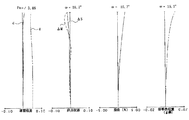
図1は、本発明の実施形態1(後述の数値実施例1に対応)のズームレンズの要部断面図、図2〜図4は実施形態1のズームレンズの広角端、中間焦点距離、望遠端における収差図である。
【0035】
図5は、本発明の実施形態2(後述の数値実施例2に対応)のズームレンズの要部断面図、図6〜図8は実施形態2のズームレンズの広角端、中間焦点距離、望遠端における収差図である。
【0036】
図9は、本発明の実施形態3(後述の数値実施例3に対応)のズームレンズの要部断面図、図10〜図12は実施形態3のズームレンズの広角端、中間焦点距離、望遠端における収差図である。
【0037】
各実施形態のレンズ断面中、L1は正の屈折力(光学的パワー=焦点距離の逆数)の第1レンズ群、L2は負の屈折力の第2レンズ群、L3は正の屈折力の第3レンズ群、L4は正の屈折力の第4レンズ群である。SPは開口絞りであり、第3群L3の前方に配置しており、ズーミングに際し、第3レンズ群L3と一体的に移動している。Gは色分解プリズムやフェースプレートや各種フィルター等に相当するガラスブロックである。IPは像面であり、CCDやCMOS等の固体撮像素子(光電変換素子)やフィルム等の感光材料が配置されている。
【0038】
各実施形態の収差図において、d,gはd線及びg線、ΔM,ΔSはメリジオナル像面、サジタル像面、倍率色収差はg線によって表している。
【0039】
図1に示した実施形態1では、広角端から望遠端へのズーミングに際し、図中の矢印に示すように、変倍のために第1レンズ群L1と第3レンズ群L3を物体側へ、第2レンズ群L2を像側へ凸状の軌跡で移動させ、変倍に伴う像面変動を補正するために第4レンズ群L4を物体側に凸状の軌跡の一部を有するように移動させている。
【0040】
又、第4レンズ群L4を光軸方向に移動させてフォーカスを行うリアフォーカス式を採用している。このため、第4レンズ群L4のズーミングの際の移動軌跡は物体距離によって異なっている。図1に示す第4レンズ群L4の実線の曲線4aと点線の曲線4bは各々無限遠物体と近距離物体にフォーカスしているときの広角端から望遠端へのズーミングの際の移動軌跡を示している。曲線4a,4bに示すように、第4レンズ群L4を広角端から望遠端へのズーミングに際して、物体側へ凸状の軌跡を有するように移動させることにより、第3レンズ群L3と第4レンズ群L4の間の空間の有効利用を図り、レンズ全長の短縮化を効果的に達成している。
【0041】
実施形態1において、例えば望遠端において無限遠物体から近距離物体へのフォーカスは、図1の直線4cに示すように第4レンズ群L4を前方へ繰り出すことにより行っている。
【0042】
実施形態1では、第3レンズ群L3をズーミングに際して物体側に移動させることにより第3レンズ群L3に主な変倍効果を持たせ、更に正の屈折力の第1レンズ群L1をズーミングに際して物体側へ移動させることで第2レンズ群L2にも変倍効果を持たせて第1レンズ群L1、第2レンズ群L2の屈折力をあまり大きくすることなく5倍程度の変倍比を容易に得ている。
【0043】
そして実施形態1では、第2レンズ群L2を、物体側から順に、負レンズG21と、物体側に凸面を向けたメニスカス形状の負レンズG22との2枚のレンズからなる貼合せレンズ、物体側に屈折力の絶対値が大きい凸面を有するメニスカス形状の正レンズG23より構成し、負レンズG21と負レンズG22の物体側に凸状の貼合わせ面に、光軸に対して回転対称な位相型の回折格子で構成される回折光学部を設け、貼合せレンズを回折光学素子としている。
【0044】
なお、回折光学部は位相型の回折格子で構成しているので、実際には所定の厚みを持つことになるが、幾何光学的には無視できる程度の厚みなので、厚みを無視する場合には回折光学面(回折面)と呼ぶこともある。 実施形態1では、球面状の貼合せ面に回折光学部を設けているが、そのベース面を非球面にすれば、更に望遠端での球面収差やコマ収差の補正が良好に行える。これは以後説明する実施形態2や3においても同様である。
【0045】
次に、図5に示した本実施形態2では、広角端から望遠端へのズーミングに際し、図5の矢印に示すのように、変倍のために第2レンズ群L2を像側へ、第3レンズ群L3を物体側へ移動させると共に、変倍に伴う像面変動を補正するために第4レンズ群L4を物体側に凸状の軌跡の一部を有しるように移動させている。
【0046】
又、第4レンズ群L4を光軸方向に移動させてフォーカスを行うリアフォーカス式を採用している。このため、やはり第4レンズ群L4のズーミングの際の移動軌跡は物体距離によって異なっている。図5に示す第4レンズ群L4の実線の曲線4aと点線の曲線4bは各々無限遠物体と近距離物体にフォーカスしているときの広角端から望遠端へのズーミングの際の移動軌跡を示している。曲線4a,4bに示すように、第4レンズ群L4を広角端から望遠端へのズーミングに際して、物体側へ凸状の軌跡を有するように移動させることにより、第3レンズ群L3と第4レンズ群L4の間の空間の有効利用を図り、レンズ全長の短縮化を効果的に達成している。
【0047】
実施形態2において、例えば望遠端において無限遠物体から近距離物体へのフォーカスは、図5の直線4cに示すように第4レンズ群L4を前方へ繰り出すことにより行っている。
【0048】
実施形態2では、ズーミングのためには第1レンズ群L1を移動させず鏡筒構造の簡素化を図っている。また、第3レンズ群L3をズーミングに際して物体側に移動させることにより第3レンズ群L3に主な変倍効果を持たせている。
【0049】
そして実施形態2では、第2レンズ群L2を、物体側から順に、負レンズG21と、物体側に凸面を向けたメニスカス形状の負レンズG22との2枚のレンズからなる貼合せレンズ、物体側に屈折力の絶対値が大きい凸面を有するメニスカス形状の正レンズG23で構成し、負レンズG21と負レンズG22の物体側に凸状の貼合わせ面(レンズ面)に、光軸に対して回転対称な位相型の回折格子で構成される回折光学部を設け、貼合せレンズを回折光学素子としている。
【0050】
図9に示した実施形態3では、広角端から望遠端へのズーミングに際し、図中の矢印に示すように、変倍のために第2レンズ群L2を像側に移動させると共に、変倍に伴う像面変動を補正するために第4レンズ群L4を物体側に凸状の軌跡の一部を有するように移動させている。
【0051】
また第4レンズ群L4を光軸方向に移動させてフォーカシングを行うリアフォーカス式を採用している。このため、第4レンズ群L4のズーミングの際の移動軌跡は物体距離によって異なっている。図9に示す第4レンズ群L4の実線の曲線4aと点線の曲線4bは各々無限遠物体と近距離物体にフォーカスしているときの広角端から望遠端へのズーミングの際の移動軌跡を示している。曲線4a、4bに示すように、第4レンズ群L4を広角端から望遠端へのズーミングに際して、物体側へ凸状の軌跡を有するように移動させることにより第3レンズ群L3と第4レンズ群L4間の空間の有効利用を図り、レンズ全長の短縮化を効果的に達成している。
【0052】
なお、実施形態3では第1レンズ群L1、第3レンズ群L3をズーム及びフォーカスの際に固定としているが、必要に応じて移動させても良い。
【0053】
実施形態3では、第2レンズ群L2を、物体側から順に、負レンズG21、像側に屈折力の絶対値が大きい凹面を有する負レンズG22、物体側に屈折力の絶対値が大きい凹面を有する負レンズG23の3枚のレンズで構成している。そして、負レンズG21と負レンズG22を貼合わせレンズとし、その物体側に凸状の貼合わせ面に、光軸に対して回転対称な位相型の回折格子で構成される回折光学部を設け、貼合せレンズを回折光学素子としている。
【0054】
更に実施形態3では、第1レンズ群L1を負レンズと正レンズの2枚のレンズを貼り合わせて構成し、その物体側に凸状の貼合わせ面にも、光軸に対して回転対称な位相型の回折格子で構成される回折光学部を形成している。通常10倍程度のズーム比の4つのレンズ群より成る4群ズームレンズでは第1レンズ群L1は1枚の負レンズと2枚の正レンズの3枚で構成され、第2レンズ群L2は2枚の負レンズと正レンズの3枚で構成されている。これに対し、実施形態3のズームレンズでは、2つの回折光学面を使用することで、第1レンズ群L1を正、負レンズの2枚で構成し、第2レンズ群L2を負レンズのみで構成してレンズ全長の短縮化を容易にしている。また第1レンズ群L1に光学的パワー(焦点距離の逆数)の大きい回折光学面を用いたときに過剰に発生する異常分散効果を第2レンズ群L2で低減する作用もある。
【0055】
実施形態1,2のように、第1レンズ群L1を1つの正レンズのみで構成しても、第2レンズ群L2の適切な面に回折光学部を設けることで、例えばd線とg線といった2波長のみの色収差を良好に補正することはできる。
【0056】
一方、実施形態3では、望遠端における2波長以外の波長に対する色収差いわゆる2次スペクトルを全可視波長範囲内で更に良好に補正するために、屈折系の色消し条件と回折系の色消し条件を最適に組み合わせている。これによって、実施形態3のズームレンズでは、特に望遠端での2次スペクトルまで含めた色収差を良好に補正して高い光学性能を得ている。
【0057】
第1レンズ群L1の色消しを回折光学部に分担させるには、回折光学部の光学的パワーは正の値を持つことが望ましい。回折光学部のパワーが負であると、通常の屈折光学系と発生する色収差の方向が同じになってしまい、回折光学部による色消し効果が出ず、光学系全域で十分な色収差の補正が行えない。
【0058】
次に各実施形態で用いた回折光学素子の構成について説明する。
【0059】
図13は回折光学素子1の回折光学部の一部拡大断面図であり、基板2に1つの層よりなる回折格子3を設けている。図14は、この回折光学素子1の回折効率の特性を示す図である。図14において横軸は波長を表し、縦軸は回折効率を表している。なお、回折効率は全透過光束に対する回折光の光量の割合であり、格子境界面での反射光などは説明が複雑になるのでここでは考慮していない。
【0060】
回折格子3の光学材料は、紫外線硬化樹脂(nd=1.513,νd=51.0)を用い、格子厚d1を1.03μmと設定し、波長530nm、+1次の回折光の回折効率が最も高くなるようにしている。すなわち、設計次数が+1次で、設計波長が530nmである。図14中において、+1次の回折光の回折効率は実線で示している。
【0061】
さらに、図14では設計次数近傍の回折次数(+1次±1次である0次光と+2次)の回折効率も併記している。図14から分かるように、設計次数での回折効率は設計波長近傍で最も高くなり、それ以外の波長では徐々に低くなる。
【0062】
この設計次数での回折効率の低下分が他の次数の回折光となり、フレアの要因となる。また、回折光学素子を複数箇所に使用した場合には、設計波長以外の波長での回折効率の低下は透過率の低下にもつながることになる。
【0063】
次に、異なる材料よりなる複数の回折格子を積層した積層型の回折光学素子について説明する。図15は積層型の回折光学素子の一部拡大断面図であり、図16はこの回折光学素子の+1次の回折光の回折効率の波長依存性を表す図である。図15の回折光学素子では、基板102上に紫外線硬化樹脂(屈折率nd=1.499、アッベ数νd=54)からなる第1の回折格子104を形成し、その上に別の回折格子105(屈折率nd=1.598、アッベ数νd=28)を形成している。この材料の組み合わせにおいて、第1の回折格子104の格子厚d1はd1=13.8μm、第2の回折格子105の格子厚d2はd2=10.5μmとしている。
【0064】
図16からも分かるように、積層構造の回折格子を備えた回折光学素子にすることで、設計次数の回折光において使用波長全域(ここでは可視域)で95%以上という高い回折効率が得ている。
【0065】
なお、前述の積層構造の回折光学素子としては、回折格子を構成する材料を紫外線硬化樹脂に限定するものではなく、他のプラスチック材等も使用できるし、基材によっては第1の層を直接基材に形成しても良い。また各格子厚が必ずしも異なる必要はなく、材料の組み合わせによっては2つの回折格子104と105の格子部の格子厚を等しくしても良い。この場合は表面に格子形状が形成されないことになるので、防塵性に優れ、回折光学素子の組立作業性を向上させることができる。更には2つの回折格子104と105を必ずしも密着させる必要はなく、空気層を隔てて2つの回折格子の層を配置しても良い。
【0066】
さて、実施形態1〜3に示したズームレンズでは、第2レンズ群L2に入射する光束の入射角度がズーム位置や画角で変化する。そこで、実施形態1〜3では、回折光学部を設ける面の曲率半径を適切な値とすることによって全ズーム域及び全画角で高い回折効率が得られるようにしている。
【0067】
具体的には、第2レンズ群L2の回折光学部を設けた貼合せ面の曲率半径をRD、第2レンズ群L2の焦点距離をf2とするとき、
−2.8 < RD/f2 < −1.2 ・・・(1)
なる条件式を満足するようにしている。
【0068】
条件式(1)の下限を超えて、貼合せ面、ひいては回折光学面の曲率が強く(大きく)なり過ぎると、特に望遠端の軸上光線に対する入射角が大きくなりすぎて回折効率が低下してしまうので良くない。逆に上限を超えて曲率が弱く(小さく)なり過ぎると広角側の画面周辺で入射角が大きくなって良くない。
【0069】
更に好ましくは条件式(1)の数値範囲を次の如く設定するのが良い。
【0070】
−2.5 < RD/f2 < −1.5 ・・・(1a)
一例として、図17に実施形態1(後述する数値実施例1)の回折光学面(貼合わせ面)における光軸からの高さhに対する光線の入射角の変動を示す。横軸が光軸からの高さで、縦軸が入射角度である。斜線を施された領域が入射光線の分布範囲である。ズーミング等で回折光学面への光線の入射角度が大きく変動すると、回折効率が低下して色フレアーの原因となる。
【0071】
各実施形態においては、負レンズG21と負レンズG22の貼合わせ面の曲率を条件式(1)を満足するように適切に設定することで、回折光学面への入射角の変動を±10度以下に抑えている。回折効率の低下を考慮すると、回折光学面での入射角の変動は±15度、望ましくは10度以内であることが必要である。d線の波長をλd、光軸からの距離をhとして、前記回折光学部によって波面に与えられる位相を、
各実施形態において、回折光学面の効果を十分に発揮するには、回折光学部が透過光の波面に与える位相φ(h)を
φ(h)=2π/λd(C2・h2+C4・h4+・・・C2・i・h2i)
但し λd:基準波長(d線)
h:光軸からの距離
C2,C4,・・・C2i:位相係数
で表し、回折光学部の有効径の1/2をH、第2レンズ群L2の焦点距離をf2とするとき、
−0.05<(C2・H2+C4・H4)/f2<−0.0007 ・・・(2)
なる条件式を満足するように回折光学部を構成する回折格子を設定している。
【0072】
条件式(2)の上限を超えると、回折光学部による色収差補正の効果が十分に得られず広角端でのg線の倍率色収差が負の方向に大きくなるので良くない。逆に上限を超えると倍率色収差が逆の正の方向に悪化するので良くない。
【0073】
更に好ましくは、条件式(2)の数値範囲を次の如く設定するのが良い。
【0074】
−0.04<(C2・H2+C4・H4)/f2<−0.001 ・・・(2a)
更に各実施形態においてズーム部のレンズ全長を短縮するには、全系の広角端と望遠端の焦点距離を各々fw,fT、第2レンズ群L2の焦点距離をf2とするとき、
【0075】
【数3】
![]()
なる条件式を満足するのが良い。
【0077】
ここで広角端と望遠端とは、変倍用のレンズ群が機構上、光軸上移動可能な範囲の両端に位置したときのズーム位置をいう。
【0078】
条件式(3)は第2レンズ群L2の屈折力に関するものであり、ズーミングに伴なう収差変動を少なくしつつ、所望の変倍比を効果的に得るためのものである。下限値を超えて第2レンズ群L2の屈折力が強くなりすぎると小型化には有利になるが、望遠端で発生する球面収差やコマ収差の補正が困難になる。逆に上限値を超えると、ズーミングの際の第2レンズ群L2の移動量が大きくなり過ぎてレンズ全長が長くなってしまうので良くない。
【0079】
更に好ましくは条件式(3)の数値範囲を次の如く設定するのが良い。
【0080】
【数4】
![]()
以下に実施形態1〜3のズームレンズの数値データに各々対応する数値実施例1〜3を示す。各数値実施例においてiは物体側からの光学面の順序を示し、Riは第i番目の光学面(第i面)の曲率半径、Diは第i面と第i+1面との間の間隔、Niとνiはそれぞれd線に対する第i番目の光学部材の屈折率、アッベ数を示す。fは焦点距離、FnoはFナンバー、ωは半画角である。
【0082】
また、数値実施例1,2の最も像側の5つの面、数値実施例3の最も像側の2つの面は、色分解プリズム、フェースプレート、各種フィルター等に相当するガラスブロックPを構成する面である。
【0083】
またkを離心率、B,C,D,E、F・・・を非球面係数、光軸からの高さhの位置での光軸方向の変位を面頂点を基準にしてxとするとき、非球面形状は、
x=(h2/R)/[1+[1−(1+k)(h/R)2]1/2]+Bh4+Ch6+Dh8+Eh10
で表示される。但しRは曲率半径である。
【0084】
回折光学面(回折面)は前述の位相関数、
φ(h)=2π/λd(C2・h2+C4・h4+・・・C2i・h2i)
の位相係数を与えることで表している。
【0085】
なお、例えば「e−Z」の表示は「10-Z」を意味する。
【0086】
各数値実施例における上述した条件式との対応を表1に示す。
【0087】
【外1】
【外2】
【外3】
【表1】
次に実施形態1〜3に示したようなズームレンズを撮影光学系として用いたデジタルスチルカメラ(光学機器)の実施形態を図18を用いて説明する。
【0095】
図18において、10はカメラ本体、11は実施形態1〜3で説明したいずれかのズームレンズによって構成された撮影光学系、12はカメラ本体に内臓されたストロボ、13は外部式ファインダー、14はシャッターボタンである。
【0096】
このように本発明のズームレンズをデジタルスチルカメラ等の光学機器に適用することにより、小型で高い光学性能を有する光学機器が実現できる。
【0097】
【発明の効果】
以上説明したように、本発明によれば、回折光学面を導入するレンズ群や回折光学部の設けられている面(曲面)の曲率を適切に設定し、回折光学部への入射角の変動を全ズーム域、全画角で抑制することによって、不要回折光を低減し、広角端から望遠端に至る全ズーム範囲にわたり良好なる光学性能を有するズームレンズ及びそれを有する光学機器を達成することができる。
【図面の簡単な説明】
【図1】 本発明の実施形態1のズームレンズのレンズ断面図
【図2】 本発明の実施形態1のズームレンズの広角端における収差図
【図3】 本発明の実施形態1のズームレンズの中間ズーム位置における収差図
【図4】 本発明の実施形態1のズームレンズの望遠端における収差図
【図5】 本発明の実施形態2のズームレンズのレンズ断面図
【図6】 本発明の実施形態2のズームレンズの広角端における収差図
【図7】 本発明の実施形態2のズームレンズの中間ズーム位置における収差図
【図8】 本発明の実施形態2のズームレンズの望遠端における収差図
【図9】 本発明の実施形態3のズームレンズのレンズ断面図
【図10】 本発明の実施形態3のズームレンズの広角端における収差図
【図11】 本発明の実施形態3のズームレンズの中間ズーム位置における収差図
【図12】 本発明の実施形態3のズームレンズの望遠端における収差図
【図13】 単層構造の回折光学素子の説明図
【図14】 単層構造の回折光学素子の波長依存特性の説明図
【図15】 積層構造の回折光学素子の説明図
【図16】 積層構造の回折光学素子の波長依存特性の説明図
【図17】 実施形態1のズームレンズの回折光学面への光束の入射角を示す説明図
【図18】 デジタルスチルカメラの要部概略図
【符号の説明】
L1 第1群
L2 第2群
L3 第3群
L4 第4群
SP 開口絞り
IP 像面
d d線
g g線
ΔS サジタル像面
ΔM メリディオナル像面
ω 画角
Fno Fナンバー[0001]
BACKGROUND OF THE INVENTION
The present invention relates to a zoom lens suitable for a digital camera, a video camera, an electronic still camera, a silver salt photographic camera, and an optical apparatus having the zoom lens, and particularly has a high zoom ratio, a large aperture ratio, and good optical performance. The present invention relates to a zoom lens in which the entire lens system is reduced in size and an optical apparatus having the same.
[0002]
[Prior art]
Recently, along with the reduction in size and weight of digital cameras and video cameras, there is a demand for shortening the total lens length, reducing the front lens diameter, and simplifying the configuration of an imaging zoom lens used therefor. As one zoom lens that achieves these objectives, a so-called rear focus type zoom lens that performs focusing (focusing) by moving a lens group other than the first lens group on the object side is known.
[0003]
In general, a rear focus type zoom lens has a smaller effective diameter of the first lens group than a zoom lens that moves the first lens group to perform focusing, thereby facilitating downsizing of the entire lens system, and close-up photography. In particular, close-up photography is facilitated, and the small and lightweight lens group is moved, so that the driving force of the lens group is small and rapid focusing is possible.
[0004]
As such a rear focus type zoom lens, for example, in Japanese Patent Laid-Open Nos. 62-24213 and 63-247316, in order from the object side, a first lens unit having a positive refractive power, a negative refractive power, The fourth lens group includes a second lens group, a third lens group having a positive refractive power, and a fourth lens group having a positive refractive power. The group is moved to correct and focus the image plane variation accompanying zooming.
[0005]
By the way, it is effective to retract the entire lens system in order to improve the storage property when the camera is not used (when not photographing). However, the zoom type zoom lens in which the second lens group has almost a zooming function is not suitable for retracting because the sensitivity of the first lens group and the second lens group to the decentration is too high.
[0006]
In this regard, in Japanese Patent Laid-Open No. 10-62687, in a zoom lens having a zoom ratio of about 3 times, in order from the object side, a first lens group having a positive refractive power, a second lens group having a negative refractive power, and a positive refraction. The first lens group is composed of a single lens and the second, third, and fourth lens groups are moved while having a fourth lens group having a third power group and a fourth lens group having a positive refractive power. A zoom lens is proposed that performs zooming, moves the fourth lens group to perform focusing, simplifies the entire optical system, and is suitable for a retractable structure.
[0007]
In this type of zoom lens, when trying to reduce the size of the entire lens system or reduce the number of lenses, axial chromatic aberration and lateral chromatic aberration increase, and digital images that require high image quality by using high-pixel image sensors It becomes difficult to apply to cameras and video cameras.
[0008]
In recent years, proposals have been made to apply a diffractive optical element to an imaging optical system as one method for suppressing the occurrence of chromatic aberration.
[0009]
For example, in Japanese Patent Application Laid-Open Nos. 4-213421 and 6-324262, the chromatic aberration is reduced by applying a diffractive optical element to a single lens.
[0010]
In US Pat. No. 5,268,790, a diffractive optical element is used for the second lens group or the third lens group constituting the zoom lens, thereby reducing the number of lenses and reducing the size of the entire lens system. .
[0011]
JP-A-11-52238, JP-A-11-52244, and the like propose zoom lenses that achieve a reduction in the number of first lens groups by providing a diffractive optical surface in the first lens group.
[0012]
Furthermore, Japanese Patent Application Laid-Open No. 11-305126 proposes a zoom lens in which a diffractive optical surface is provided on the joint surface (bonding surface) of two lenses to reduce chromatic aberration.
[0013]
In addition, when an optical system using a diffractive optical element is used as an imaging system, it is necessary to obtain sufficient diffraction efficiency over the entire visible range. In general, in a single-layer diffraction grating, diffraction efficiency decreases at wavelengths other than the design wavelength, and unnecessary diffracted light other than the design order causes color flare. In view of this, Japanese Patent Laid-Open No. 9-127322 discloses a high diffraction rate in the entire visible range by optimally selecting three different materials and two different grating thicknesses of the three diffraction gratings constituting the diffractive optical element. Has gained efficiency.
[0014]
[Problems to be solved by the invention]
Generally, when trying to correct chromatic aberration by introducing a diffractive optical surface to the zoom lens group (variable lens group), the angle of light incident on the diffractive optical surface varies greatly depending on the angle of view and focal length, so the diffraction efficiency. Changes and the amount of unnecessary diffracted light increases. In JP-A-11-52238 and JP-A-11-52244, a diffractive optical surface is provided on a lens surface convex (positive refractive power) on the image side. The difference in incident angle is large, and sufficient diffraction efficiency cannot be obtained.
[0015]
Further, in order to obtain high diffraction efficiency over the entire visible range, the diffractive optical part needs to be composed of a plurality of diffraction gratings, and the diffractive optical part needs to be set on the bonding surface having lenses on the front and back sides. In Japanese Patent Application Laid-Open No. 11-305126, a diffraction grating is provided on the bonding surface, but the incident condition of the light beam on the diffraction grating changes greatly with respect to the magnification change and the change in the angle of view.
[0016]
In view of these prior arts, the present invention appropriately sets the curvature of a surface (curved surface) on which a diffractive optical surface is introduced and a lens group and a diffractive optical unit are provided, and changes the incident angle to the diffractive optical unit. An object of the present invention is to provide a zoom lens having an excellent optical performance over the entire zoom range from the wide-angle end to the telephoto end, and an optical apparatus having the same, by reducing unnecessary next-order diffracted light by suppressing in all zoom ranges and all angles .
[0017]
[Means for Solving the Problems]
The zoom lens according to the first aspect of the present invention includes, in order from the object side, a first lens group having a positive refractive power and a second lens group having a negative refractive power that moves in the optical axis direction during zooming.In a zoom lens having only four lens groups, a third lens group having a positive refractive power and a fourth lens group having a positive refractive power that moves during zooming, as a lens groupThe second lens group has a convex bonding surface on the object side, and a diffractive optical part configured by a diffraction grating is provided on the bonding surface.When the radius of curvature of the bonding surface is RD and the focal length of the second lens group is f2,
-2.5 < RD / f2 < -1.5
Satisfy the conditionIt is characterized by that.
[0018]
A second aspect of the invention is characterized in that, in the first aspect of the invention, the diffractive optical part is formed of a laminated structure of a plurality of diffraction gratings made of materials having different dispersions.
[0019]
The invention of
φ (h) = 2π / λd (C2・ H2+ CFour・ HFour+ ... C2 ・ i・ H2i)
And ½ of the effective diameter of the diffractive optical unit is H, and the focal length of the second lens group is
When f2
-0.05 <(C2・ H2+ CFour・ HFour) / F2 <−0.0007
It is characterized by satisfying the following conditions.
[0020]
According to a fourth aspect of the invention, in the first aspect of the invention, the first to fourth lens groups are all moved during zooming.
[0021]
According to a fifth aspect of the invention, in the first aspect of the invention, the first lens group and the third lens group do not move for zooming, and the fourth lens group moves for zooming.
[0022]
A zoom lens according to a sixth aspect of the invention includes, in order from the object side, a first lens group having a positive refractive power, a second lens group having a negative refractive power that moves during zooming, a third lens group having a positive refractive power, and zooming. 4th lens group with positive refractive power that moves when movingThis lens group has only four lens groupsIn zoom lenses,
The second lens group includes a cemented lens in which two negative lenses are cemented, and a cemented surface of the cemented lens is convex on the object side and includes a diffractive optical unit configured by a diffraction grating. When the radius of curvature of the bonding surface is RD and the focal length of the second lens group is f2,
-2.8 <RD / f2 <-1.2
It is characterized by satisfying the following conditions.
[0023]
The invention of claim 7 is the invention of claim 6, wherein the wavelength given by the diffractive optical part to the wavefront is λd and the distance from the optical axis is h,
φ (h) = 2π / λd (C2・ H2+ CFour・ HFour+ ... C2 ・ i・ H2i)
Where ½ of the effective diameter of the diffractive optical part is H, and the focal length of the second lens group is f2.
-0.05 <(C2・ H2+ CFour・ HFour) /f2 <-0.0007
It is characterized by satisfying the following conditions.
[0024]
The invention of claim 8 is the invention of any one of claims 1 to 7, wherein the focal lengths at the wide-angle end and the telephoto end of the entire system are fW and fT,
[Expression 2]
[0025]
The invention of claim 9 is characterized in that, in the invention of any one of claims 1 to 8, an image is formed on the photoelectric conversion element.
[0026]
An optical apparatus according to a tenth aspect of the present invention is the zoom lens according to any one of the first to ninth aspects.A photoelectric conversion element that receives an image formed by the zoom lens;It is characterized by having.
[0033]
DETAILED DESCRIPTION OF THE INVENTION
Embodiments of a zoom lens and an optical apparatus according to the present invention will be described below with reference to the drawings.
[0034]
1 is a cross-sectional view of a main part of a zoom lens according to Embodiment 1 (corresponding to Numerical Example 1 described later) of the present invention, and FIGS. 2 to 4 are wide-angle end, intermediate focal length, and telephoto of the zoom lens according to Embodiment 1. It is an aberration diagram at the end.
[0035]
5 is a cross-sectional view of a main part of a zoom lens according to Embodiment 2 (corresponding to Numerical Example 2 described later) of the present invention, and FIGS. 6 to 8 are wide-angle end, intermediate focal length, and telephoto of the zoom lens according to Embodiment 2. It is an aberration diagram at the end.
[0036]
9 is a cross-sectional view of an essential part of a zoom lens according to Embodiment 3 (corresponding to Numerical Example 3 described later) of the present invention, and FIGS. 10 to 12 are a wide angle end, an intermediate focal length, and a telephoto end of the zoom lens according to
[0037]
In the lens cross section of each embodiment, L1 is a first lens unit having a positive refractive power (optical power = reciprocal of focal length), L2 is a second lens unit having a negative refractive power, and L3 is a first lens unit having a positive refractive power. The third lens group, L4, is a fourth lens group having a positive refractive power. SP is an aperture stop which is disposed in front of the third lens unit L3 and moves integrally with the third lens unit L3 during zooming. G is a glass block corresponding to a color separation prism, a face plate, various filters, and the like. IP is an image plane, on which a solid-state imaging device (photoelectric conversion device) such as a CCD or CMOS, or a photosensitive material such as a film is disposed.
[0038]
In the aberration diagrams of the respective embodiments, d and g are represented by d-line and g-line, ΔM and ΔS are represented by meridional image surface, sagittal image surface, and lateral chromatic aberration are represented by g-line.
[0039]
In the first embodiment shown in FIG. 1, during zooming from the wide-angle end to the telephoto end, as shown by the arrows in the drawing, the first lens unit L1 and the third lens unit L3 are moved to the object side for zooming. The second lens unit L2 is moved along a convex locus toward the image side, and the fourth lens unit L4 is moved so as to have a part of the convex locus toward the object side in order to correct the image plane variation caused by zooming. I am letting.
[0040]
Further, a rear focus type is employed in which focusing is performed by moving the fourth lens unit L4 in the optical axis direction. For this reason, the movement locus during zooming of the fourth lens unit L4 differs depending on the object distance. A
[0041]
In Embodiment 1, for example, focusing from an infinitely distant object to a close object at the telephoto end is performed by extending the fourth lens unit L4 forward as shown by a
[0042]
In the first embodiment, the third lens unit L3 is moved to the object side during zooming to give the third lens unit L3 a main zooming effect, and further, the first lens unit L1 having a positive refractive power is moved to the object side during zooming. By moving the second lens unit L2 to the side, the second lens unit L2 also has a zooming effect, and a zoom ratio of about 5 times can be easily achieved without increasing the refractive power of the first lens unit L1 and the second lens unit L2. It has gained.
[0043]
In the first embodiment, the second lens unit L2 is composed of, in order from the object side, a cemented lens including two lenses, a negative lens G21 and a meniscus negative lens G22 having a convex surface facing the object side. And a meniscus-shaped positive lens G23 having a convex surface with a large absolute value of refractive power, and a phase-type rotationally symmetric with respect to the optical axis on the object-side bonding surfaces of the negative lens G21 and the negative lens G22. A diffractive optical part composed of the above diffraction grating is provided, and a bonded lens is used as a diffractive optical element.
[0044]
Since the diffractive optical part is composed of a phase type diffraction grating, the diffractive optical part actually has a predetermined thickness, but the thickness is negligible in terms of geometrical optics. Sometimes called a diffractive optical surface (diffractive surface). In the first embodiment, the diffractive optical unit is provided on the spherical bonding surface. However, if the base surface is aspherical, spherical aberration and coma at the telephoto end can be corrected more satisfactorily. The same applies to Embodiments 2 and 3 described below.
[0045]
Next, in the second embodiment shown in FIG. 5, during zooming from the wide-angle end to the telephoto end, as shown by the arrow in FIG. 5, the second lens unit L2 is moved to the image side for zooming. The third lens unit L3 is moved to the object side, and the fourth lens unit L4 is moved so as to have a part of a convex locus on the object side in order to correct the image plane variation caused by zooming. .
[0046]
Further, a rear focus type is employed in which focusing is performed by moving the fourth lens unit L4 in the optical axis direction. For this reason, the movement locus during zooming of the fourth lens unit L4 also differs depending on the object distance. A
[0047]
In Embodiment 2, for example, focusing from an infinitely distant object to a close object at the telephoto end is performed by extending the fourth lens unit L4 forward as indicated by a
[0048]
In the second embodiment, the lens barrel structure is simplified without moving the first lens unit L1 for zooming. Further, the third lens unit L3 is moved toward the object side during zooming, so that the third lens unit L3 has a main zooming effect.
[0049]
In the second embodiment, the second lens unit L2 is composed of two lenses, a negative lens G21 and a meniscus negative lens G22 having a convex surface facing the object side, in order from the object side. The lens is composed of a meniscus positive lens G23 having a convex surface with a large absolute value of refractive power, and is rotated with respect to the optical axis on the object side of the negative lens G21 and the negative lens G22. A diffractive optical part composed of a symmetric phase type diffraction grating is provided, and a bonded lens is used as a diffractive optical element.
[0050]
In
[0051]
In addition, a rear focus type that performs focusing by moving the fourth lens unit L4 in the optical axis direction is adopted. For this reason, the movement locus during zooming of the fourth lens unit L4 differs depending on the object distance. The
[0052]
In the third embodiment, the first lens unit L1 and the third lens unit L3 are fixed during zooming and focusing. However, they may be moved as necessary.
[0053]
In the third embodiment, in order from the object side, the second lens unit L2 includes a negative lens G21, a negative lens G22 having a concave surface with a large absolute value of refractive power on the image side, and a concave surface with a large absolute value of refractive power on the object side. The negative lens G23 has three lenses. Then, the negative lens G21 and the negative lens G22 are used as a bonding lens, and a diffractive optical unit including a phase-type diffraction grating that is rotationally symmetric with respect to the optical axis is provided on a convex bonding surface on the object side. The bonded lens is a diffractive optical element.
[0054]
Furthermore, in
[0055]
Even if the first lens unit L1 is configured by only one positive lens as in the first and second embodiments, by providing a diffractive optical unit on an appropriate surface of the second lens unit L2, for example, d line and g line Thus, it is possible to satisfactorily correct the chromatic aberration of only two wavelengths.
[0056]
On the other hand, in the third embodiment, in order to more favorably correct chromatic aberration so-called secondary spectrum for wavelengths other than the two wavelengths at the telephoto end within the entire visible wavelength range, the achromatic condition for the refraction system and the achromatic condition for the diffraction system are changed. Combined optimally. Thereby, in the zoom lens according to
[0057]
In order to share the achromaticity of the first lens unit L1 to the diffractive optical unit, it is desirable that the optical power of the diffractive optical unit has a positive value. If the power of the diffractive optical unit is negative, the direction of chromatic aberration generated will be the same as that of a normal refractive optical system, and the achromatic effect by the diffractive optical unit will not be produced, and sufficient correction of chromatic aberration will be possible throughout the optical system. I can't.
[0058]
Next, the configuration of the diffractive optical element used in each embodiment will be described.
[0059]
FIG. 13 is a partially enlarged cross-sectional view of the diffractive optical portion of the diffractive optical element 1, and the substrate 2 is provided with a
[0060]
The optical material of the
[0061]
Further, FIG. 14 also shows the diffraction efficiency of diffraction orders in the vicinity of the design order (+ 1st order ± 1st order 0th order light and + 2nd order). As can be seen from FIG. 14, the diffraction efficiency at the design order is highest near the design wavelength, and gradually decreases at other wavelengths.
[0062]
The decrease in diffraction efficiency at this design order becomes diffracted light of other orders, which causes flare. In addition, when diffractive optical elements are used at a plurality of locations, a decrease in diffraction efficiency at a wavelength other than the design wavelength leads to a decrease in transmittance.
[0063]
Next, a laminated diffractive optical element in which a plurality of diffraction gratings made of different materials are laminated will be described. FIG. 15 is a partially enlarged cross-sectional view of a laminated diffractive optical element, and FIG. 16 is a diagram showing the wavelength dependence of the diffraction efficiency of the + 1st order diffracted light of this diffractive optical element. In the diffractive optical element of FIG. 15, a
[0064]
As can be seen from FIG. 16, by using a diffractive optical element provided with a diffraction grating having a laminated structure, a high diffraction efficiency of 95% or more is obtained in the entire range of wavelengths used (in this case, the visible region) in the diffracted light of the designed order. Yes.
[0065]
The diffractive optical element having the above-described laminated structure is not limited to the material that constitutes the diffraction grating, but other plastic materials may be used. Depending on the substrate, the first layer may be directly You may form in a base material. The grating thicknesses are not necessarily different, and the grating thicknesses of the grating portions of the two
[0066]
In the zoom lenses shown in the first to third embodiments, the incident angle of the light beam incident on the second lens unit L2 varies depending on the zoom position and the angle of view. Therefore, in the first to third embodiments, by setting the radius of curvature of the surface on which the diffractive optical unit is provided to an appropriate value, high diffraction efficiency can be obtained in the entire zoom range and the entire angle of view.
[0067]
Specifically, when the radius of curvature of the bonding surface provided with the diffractive optical part of the second lens unit L2 is RD, and the focal length of the second lens unit L2 is f2,
-2.8 <RD / f2 <-1.2 (1)
The following conditional expression is satisfied.
[0068]
Exceeding the lower limit of conditional expression (1), if the curvature of the bonding surface, and hence the diffractive optical surface, becomes too strong (large), the incident angle with respect to the axial ray at the telephoto end becomes too large and the diffraction efficiency decreases. It ’s not good. On the other hand, if the curvature exceeds the upper limit and the curvature becomes too weak (small), the incident angle becomes large around the wide-angle screen.
[0069]
More preferably, the numerical range of conditional expression (1) is set as follows.
[0070]
−2.5 <RD / f2 <−1.5 (1a)
As an example, FIG. 17 shows the variation of the incident angle of the light beam with respect to the height h from the optical axis on the diffractive optical surface (bonding surface) of Embodiment 1 (Numerical Example 1 described later). The horizontal axis is the height from the optical axis, and the vertical axis is the incident angle. The hatched area is the distribution range of incident light. If the incident angle of the light beam on the diffractive optical surface fluctuates greatly due to zooming or the like, the diffraction efficiency is lowered, causing color flare.
[0071]
In each embodiment, by appropriately setting the curvature of the bonding surfaces of the negative lens G21 and the negative lens G22 so as to satisfy the conditional expression (1), the variation of the incident angle on the diffractive optical surface is ± 10 degrees. I keep it below. Considering the decrease in diffraction efficiency, the variation of the incident angle on the diffractive optical surface needs to be ± 15 degrees, preferably within 10 degrees. Assuming that the wavelength of the d-line is λd and the distance from the optical axis is h, the phase given to the wavefront by the diffractive optical unit is
In each embodiment, in order to fully demonstrate the effect of the diffractive optical surface, the phase φ (h) given to the wavefront of the transmitted light by the diffractive optical unit is set.
φ (h) = 2π / λd (C2・ H2+ CFour・ HFour+ ... C2 ・i・ H2i)
Where λd: Reference wavelength (d-line)
h: Distance from the optical axis
C2, CFour・ ・ ・ ・ ・ ・ C2i: Phase coefficient
Where ½ of the effective diameter of the diffractive optical unit is H, and the focal length of the second lens unit L2 is f2.
−0.05 <(C2・ H2+ CFour・ HFour) / F2 <−0.0007 (2)
The diffraction grating constituting the diffractive optical part is set so as to satisfy the following conditional expression.
[0072]
If the upper limit of conditional expression (2) is exceeded, the effect of correcting chromatic aberration by the diffractive optical part cannot be sufficiently obtained, and the lateral chromatic aberration of g-line at the wide-angle end increases in the negative direction, which is not good. On the contrary, if the upper limit is exceeded, the lateral chromatic aberration is worsened in the reverse positive direction.
[0073]
More preferably, the numerical range of conditional expression (2) is set as follows.
[0074]
-0.04 <(C2・ H2+ CFour・ HFour) / F2 <−0.001 (2a)
Further, in each embodiment, in order to shorten the total lens length of the zoom unit, when the focal lengths of the wide-angle end and the telephoto end of the entire system are fw and fT, and the focal length of the second lens unit L2 is f2,
[0075]
[Equation 3]
![]()
It is good to satisfy the following conditional expression.
[0077]
Here, the wide-angle end and the telephoto end refer to zoom positions when the lens unit for zooming is positioned at both ends of a range that can move on the optical axis due to the mechanism.
[0078]
Conditional expression (3) relates to the refractive power of the second lens unit L2, and is to effectively obtain a desired zoom ratio while reducing aberration fluctuations associated with zooming. If the refractive power of the second lens unit L2 is too strong beyond the lower limit, it is advantageous for miniaturization, but it becomes difficult to correct spherical aberration and coma generated at the telephoto end. Conversely, if the upper limit is exceeded, the amount of movement of the second lens unit L2 during zooming becomes too large, and the total lens length becomes long, which is not good.
[0079]
More preferably, the numerical range of conditional expression (3) is set as follows.
[0080]
[Expression 4]
![]()
Numerical Examples 1 to 3 corresponding to the numerical data of the zoom lenses of Embodiments 1 to 3, respectively, are shown below. In each numerical example, i indicates the order of the optical surfaces from the object side, Ri is the radius of curvature of the i-th optical surface (i-th surface), Di is the distance between the i-th surface and the i + 1-th surface, Ni and νi represent the refractive index and Abbe number of the i-th optical member with respect to the d-line, respectively. f is a focal length, Fno is an F number, and ω is a half angle of view.
[0082]
Further, the five surfaces closest to the image side in Numerical Examples 1 and 2 and the two surfaces closest to the image side in Numerical Example 3 constitute a glass block P corresponding to a color separation prism, a face plate, various filters, and the like. Surface.
[0083]
When k is the eccentricity, B, C, D, E, F,... Are aspheric coefficients, and the displacement in the optical axis direction at the position of the height h from the optical axis is x based on the surface vertex. The aspheric shape is
x = (h2/ R) / [1+ [1- (1 + k) (h / R)2]1/2] + BhFour+ Ch6+ Dh8+ EhTen
Is displayed. Where R is the radius of curvature.
[0084]
The diffractive optical surface (diffractive surface) is the aforementioned phase function,
φ (h) = 2π / λd (C2・ H2+ CFour・ HFour+ ... C2i・ H2i)
This is expressed by giving the phase coefficient of.
[0085]
For example, the display of “e-Z” is “10-Z"Means.
[0086]
Table 1 shows the correspondence with the above-described conditional expressions in each numerical example.
[0087]
[Outside 1]
[Outside 2]
[Outside 3]
[Table 1]
Next, an embodiment of a digital still camera (optical apparatus) using the zoom lens as shown in Embodiments 1 to 3 as a photographing optical system will be described with reference to FIG.
[0095]
In FIG. 18, 10 is a camera body, 11 is a photographing optical system constituted by any of the zoom lenses described in the first to third embodiments, 12 is a strobe built in the camera body, 13 is an external viewfinder, and 14 is Shutter button.
[0096]
In this way, by applying the zoom lens of the present invention to an optical apparatus such as a digital still camera, a small optical apparatus having high optical performance can be realized.
[0097]
【The invention's effect】
As described above, according to the present invention, the curvature of the surface (curved surface) provided with the lens group and the diffractive optical unit for introducing the diffractive optical surface is appropriately set, and the incident angle to the diffractive optical unit varies. To achieve a zoom lens having excellent optical performance over the entire zoom range from the wide-angle end to the telephoto end and an optical apparatus having the same. Can do.
[Brief description of the drawings]
FIG. 1 is a lens cross-sectional view of a zoom lens according to a first embodiment of the present invention.
FIG. 2 is an aberration diagram at the wide-angle end of the zoom lens according to the first embodiment of the present invention.
FIG. 3 is an aberration diagram at the intermediate zoom position of the zoom lens according to the first embodiment of the present invention.
FIG. 4 is an aberration diagram at the telephoto end of the zoom lens according to the first embodiment of the present invention.
FIG. 5 is a lens cross-sectional view of a zoom lens according to a second embodiment of the present invention.
FIG. 6 is an aberration diagram at the wide-angle end of the zoom lens according to the second embodiment of the present invention.
FIG. 7 is an aberration diagram at an intermediate zoom position of the zoom lens according to the second embodiment of the present invention.
FIG. 8 is an aberration diagram at the telephoto end of the zoom lens according to the second embodiment of the present invention.
FIG. 9 is a lens cross-sectional view of a zoom lens according to
FIG. 10 is an aberration diagram at the wide-angle end of the zoom lens according to the third embodiment of the present invention.
FIG. 11 is an aberration diagram at an intermediate zoom position of the zoom lens according to the third embodiment of the present invention.
FIG. 12 shows aberration diagrams at the telephoto end of the zoom lens according to the third embodiment of the present invention.
FIG. 13 is an explanatory diagram of a diffractive optical element having a single-layer structure.
FIG. 14 is an explanatory diagram of wavelength dependence characteristics of a diffractive optical element having a single layer structure.
FIG. 15 is an explanatory diagram of a diffractive optical element having a laminated structure.
FIG. 16 is an explanatory diagram of wavelength dependence characteristics of a diffractive optical element having a laminated structure.
FIG. 17 is an explanatory diagram showing the incident angle of a light beam on the diffractive optical surface of the zoom lens according to the first embodiment.
FIG. 18 is a schematic view of the main part of a digital still camera.
[Explanation of symbols]
L1 first group
L2 second group
L3 3rd group
L4 4th group
SP Aperture stop
IP image plane
d d line
g g line
ΔS Sagittal image plane
ΔM Meridional image plane
ω angle of view
Fno F number
Claims (10)
−2.5 < RD/f2 < −1.5
なる条件を満足することを特徴とするズームレンズ。In order from the object side, a first lens unit having a positive refractive power, a second lens unit having a negative refractive power moving in the optical axis direction during zooming, a third lens group having a positive refractive power, and a positive refraction moving during zooming. In the zoom lens having only the four lens groups of the fourth lens group of force as the lens group, the second lens group has a convex bonding surface on the object side, and is configured by a diffraction grating on the bonding surface. When the radius of curvature of the bonding surface is RD and the focal length of the second lens group is f2,
-2.5 < RD / f2 < -1.5
A zoom lens characterized by satisfying the following conditions:
φ(h)=2π/λd(C2・h2+C4・h4+・・・C2 ・ i・h2i)
で表し、前記回折光学部の有効径の1/2をH、前記第2レンズ群の焦点距離を
f2とするとき、
−0.05 <(C2・H2+C4・H4)/f2 < −0.0007
なる条件を満足することを特徴とする請求項1又は2に記載のズームレンズ。Assuming that the wavelength of the d-line is λd and the distance from the optical axis is h, the phase given to the wavefront by the diffractive optical unit is
φ (h) = 2π / λd (C 2 · h 2 + C 4 · h 4 +... C 2 · i · h 2i )
And ½ of the effective diameter of the diffractive optical unit is H, and the focal length of the second lens group is f2.
−0.05 <(C 2 · H 2 + C 4 · H 4 ) / f2 <−0.0007
The zoom lens according to claim 1 , wherein the following condition is satisfied.
該第2レンズ群は、2つの負レンズを接合した貼合せレンズを有し、該貼合せレンズの貼合せ面は、物体側に凸状で、且つ回折格子により構成される回折光学部が設けられており、該貼合せ面の曲率半径をRD、該第2レンズ群の焦点距離をf2とするとき、
−2.8 < RD/f2 < −1.2
なる条件を満足することを特徴とするズームレンズ。In order from the object side, a first lens unit having a positive refractive power, a second lens unit having a negative refractive power moving during zooming, a third lens group having a positive refractive power, and a fourth lens having a positive refractive power moving during zooming. In a zoom lens having only four lens groups as a lens group ,
The second lens group includes a cemented lens in which two negative lenses are cemented, and the cemented surface of the cemented lens is provided with a diffractive optical unit that is convex on the object side and includes a diffraction grating. When the radius of curvature of the bonding surface is RD and the focal length of the second lens group is f2,
-2.8 <RD / f2 <-1.2
A zoom lens that satisfies the following conditions:
φ(h)=2π/λd(C2・h2+C4・h4+・・・C2 ・ i・h2i)
で表し、該回折光学部の有効径の1/2をH、第2レンズ群の焦点距離をf2とするとき、
−0.05 <(C2・H2+C4・H4)/f2 < −0.0007
なる条件を満足することを特徴とする請求項6のズームレンズ。Assuming that the wavelength of the d-line is λd and the distance from the optical axis is h, the phase given to the wavefront by the diffractive optical unit is
φ (h) = 2π / λd (C 2 · h 2 + C 4 · h 4 +... C 2 · i · h 2i )
Where ½ of the effective diameter of the diffractive optical part is H, and the focal length of the second lens group is f2.
−0.05 <(C 2 · H 2 + C 4 · H 4 ) / f2 <−0.0007
The zoom lens according to claim 6 , wherein the following condition is satisfied.
Priority Applications (2)
| Application Number | Priority Date | Filing Date | Title |
|---|---|---|---|
| JP2002016944A JP3720767B2 (en) | 2002-01-25 | 2002-01-25 | Zoom lens and optical apparatus having the same |
| US10/351,570 US6763186B2 (en) | 2002-01-25 | 2003-01-24 | Zoom lens, and camera incorporating such zoom lens |
Applications Claiming Priority (1)
| Application Number | Priority Date | Filing Date | Title |
|---|---|---|---|
| JP2002016944A JP3720767B2 (en) | 2002-01-25 | 2002-01-25 | Zoom lens and optical apparatus having the same |
Publications (3)
| Publication Number | Publication Date |
|---|---|
| JP2003215456A JP2003215456A (en) | 2003-07-30 |
| JP2003215456A5 JP2003215456A5 (en) | 2005-04-07 |
| JP3720767B2 true JP3720767B2 (en) | 2005-11-30 |
Family
ID=27652815
Family Applications (1)
| Application Number | Title | Priority Date | Filing Date |
|---|---|---|---|
| JP2002016944A Expired - Lifetime JP3720767B2 (en) | 2002-01-25 | 2002-01-25 | Zoom lens and optical apparatus having the same |
Country Status (1)
| Country | Link |
|---|---|
| JP (1) | JP3720767B2 (en) |
Cited By (1)
| Publication number | Priority date | Publication date | Assignee | Title |
|---|---|---|---|---|
| WO2020019705A1 (en) * | 2018-07-26 | 2020-01-30 | 华为技术有限公司 | Camera lens, camera module, and terminal |
Families Citing this family (4)
| Publication number | Priority date | Publication date | Assignee | Title |
|---|---|---|---|---|
| JP5025232B2 (en) * | 2006-11-20 | 2012-09-12 | オリンパスイメージング株式会社 | Imaging device using variable magnification optical system |
| JP5202076B2 (en) * | 2008-04-08 | 2013-06-05 | キヤノン株式会社 | Zoom lens and imaging apparatus having the same |
| JP5393278B2 (en) * | 2009-06-16 | 2014-01-22 | オリンパスイメージング株式会社 | Zoom lens and image pickup apparatus including the same |
| JP2012078397A (en) | 2010-09-30 | 2012-04-19 | Canon Inc | Optical system including diffraction grating, and optical instrument |
-
2002
- 2002-01-25 JP JP2002016944A patent/JP3720767B2/en not_active Expired - Lifetime
Cited By (1)
| Publication number | Priority date | Publication date | Assignee | Title |
|---|---|---|---|---|
| WO2020019705A1 (en) * | 2018-07-26 | 2020-01-30 | 华为技术有限公司 | Camera lens, camera module, and terminal |
Also Published As
| Publication number | Publication date |
|---|---|
| JP2003215456A (en) | 2003-07-30 |
Similar Documents
| Publication | Publication Date | Title |
|---|---|---|
| JP4764051B2 (en) | Zoom lens and imaging apparatus having the same | |
| CN107621690B (en) | Zoom optical system | |
| JP4817699B2 (en) | Zoom lens and imaging apparatus having the same | |
| JP3542552B2 (en) | Zoom lens and optical device using the same | |
| JP4366110B2 (en) | Zoom lens and optical apparatus having the same | |
| US7492526B2 (en) | High zoom ratio zoom lens, optical apparatus using the same, and method for varying focal length | |
| JP5309553B2 (en) | Zoom lens and optical apparatus provided with the zoom lens | |
| JP4636812B2 (en) | Zoom lens | |
| JP2002244044A (en) | Zoom lens and optical instrument using it | |
| JP4182088B2 (en) | Zoom lens and optical apparatus having the same | |
| JP4366063B2 (en) | Zoom lens and camera having the same | |
| JP5601586B2 (en) | Optical system and optical equipment | |
| JP4578869B2 (en) | 3 group zoom lens | |
| JP5395495B2 (en) | Variable magnification optical system | |
| JP4933276B2 (en) | Zoom lens | |
| JP4989235B2 (en) | Zoom lens | |
| US6865027B2 (en) | Zoom lens and camera having the same | |
| JP6938841B2 (en) | Zoom lens and optical equipment | |
| JP5935879B2 (en) | Zoom lens and optical device | |
| JP3720767B2 (en) | Zoom lens and optical apparatus having the same | |
| JP2003215452A (en) | Zoom lens and optical equipment having the same | |
| JP2004252101A (en) | Super wide angle lens | |
| JP4470141B2 (en) | Zoom lens | |
| JP5058634B2 (en) | Zoom lens and imaging apparatus having the same | |
| JP2001318316A (en) | Zoom lens and optical apparatus using the same |
Legal Events
| Date | Code | Title | Description |
|---|---|---|---|
| A521 | Request for written amendment filed |
Free format text: JAPANESE INTERMEDIATE CODE: A523 Effective date: 20040601 |
|
| A621 | Written request for application examination |
Free format text: JAPANESE INTERMEDIATE CODE: A621 Effective date: 20040601 |
|
| A977 | Report on retrieval |
Free format text: JAPANESE INTERMEDIATE CODE: A971007 Effective date: 20050516 |
|
| A131 | Notification of reasons for refusal |
Free format text: JAPANESE INTERMEDIATE CODE: A131 Effective date: 20050531 |
|
| A521 | Request for written amendment filed |
Free format text: JAPANESE INTERMEDIATE CODE: A523 Effective date: 20050727 |
|
| TRDD | Decision of grant or rejection written | ||
| A01 | Written decision to grant a patent or to grant a registration (utility model) |
Free format text: JAPANESE INTERMEDIATE CODE: A01 Effective date: 20050906 |
|
| A61 | First payment of annual fees (during grant procedure) |
Free format text: JAPANESE INTERMEDIATE CODE: A61 Effective date: 20050908 |
|
| R150 | Certificate of patent or registration of utility model |
Free format text: JAPANESE INTERMEDIATE CODE: R150 |
|
| FPAY | Renewal fee payment (event date is renewal date of database) |
Free format text: PAYMENT UNTIL: 20090916 Year of fee payment: 4 |
|
| FPAY | Renewal fee payment (event date is renewal date of database) |
Free format text: PAYMENT UNTIL: 20090916 Year of fee payment: 4 |
|
| FPAY | Renewal fee payment (event date is renewal date of database) |
Free format text: PAYMENT UNTIL: 20100916 Year of fee payment: 5 |
|
| FPAY | Renewal fee payment (event date is renewal date of database) |
Free format text: PAYMENT UNTIL: 20100916 Year of fee payment: 5 |
|
| FPAY | Renewal fee payment (event date is renewal date of database) |
Free format text: PAYMENT UNTIL: 20110916 Year of fee payment: 6 |
|
| FPAY | Renewal fee payment (event date is renewal date of database) |
Free format text: PAYMENT UNTIL: 20110916 Year of fee payment: 6 |
|
| FPAY | Renewal fee payment (event date is renewal date of database) |
Free format text: PAYMENT UNTIL: 20120916 Year of fee payment: 7 |