JP3720008B2 - Variable wavelength light source - Google Patents
Variable wavelength light source Download PDFInfo
- Publication number
- JP3720008B2 JP3720008B2 JP2002284995A JP2002284995A JP3720008B2 JP 3720008 B2 JP3720008 B2 JP 3720008B2 JP 2002284995 A JP2002284995 A JP 2002284995A JP 2002284995 A JP2002284995 A JP 2002284995A JP 3720008 B2 JP3720008 B2 JP 3720008B2
- Authority
- JP
- Japan
- Prior art keywords
- substrate
- movable plate
- light source
- diffraction grating
- actuator
- Prior art date
- Legal status (The legal status is an assumption and is not a legal conclusion. Google has not performed a legal analysis and makes no representation as to the accuracy of the status listed.)
- Expired - Lifetime
Links
- 239000000758 substrate Substances 0.000 claims description 111
- 244000126211 Hericium coralloides Species 0.000 claims description 8
- 230000003287 optical effect Effects 0.000 claims description 7
- 230000008859 change Effects 0.000 claims description 6
- 239000010410 layer Substances 0.000 description 15
- 238000004519 manufacturing process Methods 0.000 description 12
- 239000002184 metal Substances 0.000 description 12
- 238000010586 diagram Methods 0.000 description 10
- 238000000034 method Methods 0.000 description 10
- 125000006850 spacer group Chemical group 0.000 description 9
- 238000005530 etching Methods 0.000 description 8
- XUIMIQQOPSSXEZ-UHFFFAOYSA-N Silicon Chemical compound [Si] XUIMIQQOPSSXEZ-UHFFFAOYSA-N 0.000 description 7
- 229910052710 silicon Inorganic materials 0.000 description 7
- 239000010703 silicon Substances 0.000 description 7
- 239000000463 material Substances 0.000 description 6
- 230000008569 process Effects 0.000 description 5
- 238000004891 communication Methods 0.000 description 4
- 230000005684 electric field Effects 0.000 description 4
- 229910004298 SiO 2 Inorganic materials 0.000 description 3
- VYPSYNLAJGMNEJ-UHFFFAOYSA-N Silicium dioxide Chemical compound O=[Si]=O VYPSYNLAJGMNEJ-UHFFFAOYSA-N 0.000 description 2
- 239000000853 adhesive Substances 0.000 description 2
- 230000001070 adhesive effect Effects 0.000 description 2
- 230000001747 exhibiting effect Effects 0.000 description 2
- 230000004048 modification Effects 0.000 description 2
- 238000012986 modification Methods 0.000 description 2
- 230000005540 biological transmission Effects 0.000 description 1
- 230000015572 biosynthetic process Effects 0.000 description 1
- 229910052681 coesite Inorganic materials 0.000 description 1
- 210000001520 comb Anatomy 0.000 description 1
- 230000008878 coupling Effects 0.000 description 1
- 238000010168 coupling process Methods 0.000 description 1
- 238000005859 coupling reaction Methods 0.000 description 1
- 229910052906 cristobalite Inorganic materials 0.000 description 1
- 230000000694 effects Effects 0.000 description 1
- 230000004927 fusion Effects 0.000 description 1
- 239000011521 glass Substances 0.000 description 1
- 238000009616 inductively coupled plasma Methods 0.000 description 1
- 239000012212 insulator Substances 0.000 description 1
- 230000007246 mechanism Effects 0.000 description 1
- 239000013307 optical fiber Substances 0.000 description 1
- 238000000206 photolithography Methods 0.000 description 1
- 229920002120 photoresistant polymer Polymers 0.000 description 1
- 238000001020 plasma etching Methods 0.000 description 1
- 238000002310 reflectometry Methods 0.000 description 1
- 239000000377 silicon dioxide Substances 0.000 description 1
- 235000012239 silicon dioxide Nutrition 0.000 description 1
- 239000002356 single layer Substances 0.000 description 1
- 229910052682 stishovite Inorganic materials 0.000 description 1
- 229910052905 tridymite Inorganic materials 0.000 description 1
- 238000007740 vapor deposition Methods 0.000 description 1
Images
Landscapes
- Mechanical Light Control Or Optical Switches (AREA)
- Semiconductor Lasers (AREA)
Description
【0001】
【発明の属する技術分野】
本発明は、外部共振器型の可変波長光源において、容易に製造でき、波長可変範囲を広くするための技術に関する。
【0002】
【従来の技術】
近年、インターネットの普及により、通信回線のトラフィックが増加の一途を辿っており、伝送容量の限界が切実な問題になっている。
【0003】
これを解決するための手法として、1本の光ファイバで波長の異なる複数の光信号を伝送するWDMシステムが開発され、実際の通信回線に用いられるようになってきた。
【0004】
このようなWDM方式の通信回線では波長を任意に設定できる光源、即ち可変波長光源が不可欠であり、この種の可変波長光源としてはリトマン型と呼ばれる外部共振器型の可変波長光源が周知である。
【0005】
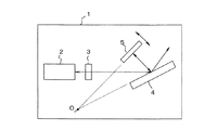
外部共振器型の可変波長光源は、基本的に図23に示す構造を有している。
図23に示した可変波長光源は、基台1に固定されたレーザ光源2から出射された光をコリメートレンズ3によって平行光に変換して基台1に固定された回折格子4に入射し、その入射光に対して回折格子4が出射する回折光を、その回折面を延長した面上の所定位置Oを中心に回転できるように支持されたミラー5に入射し、ミラー5によって反射された反射光を回折格子4へ入射させ、その反射光に対する回折光を回折格子4からコリメートレンズ3を介してレーザ光源2に戻す構造を有している。
【0006】
この構造の可変波長光源では、レーザ光源2から出射された光の波長成分のうち、ミラー5の反射面に直交する波長成分のみがレーザ光源2に戻ることになり、レーザ光源2はその戻ってきた特定波長の光で励起(共振)されてその特定波長(共振波長)の光を出射する。
【0007】
この共振波長は、回折格子4に対するミラー5の角度によって決まり、前記したように、ミラー5を回折格子4の回折面の延長した面上の所定位置を中心に回転させることで、ミラー5の角度に対して共振波長を連続的に可変することができる。
【0008】
このような基本構造を有する外部共振器型の可変波長光源を実際に通信システムの光源として用いる場合、ミラー5を回転させるためのアクチュエータとして、小型で精密な回転移動が可能なものが要求されている。
【0009】
これを満たすものとして、従来では、図24〜図27に示すように、平板構造のアクチュエータ6を用い、その上にミラー5を垂直に立てるように固定したものが知られている(特許文献1参照)。
【0010】
このアクチュエータ6は、導電性の高い2枚のシリコンの基板7、8を絶縁膜(SiO2)9を挟んで貼付け、その上側の基板8に対してエッチング処理を行なうことで形成したものである。
【0011】
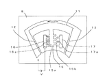
上側の基板8には扇状の穴10が形成されており、その内側には外形が扇型の可動部11が形成されている。なお、穴10の底面は絶縁膜9がエッチングによって除去されて下側の基板7の表面が漏出している。
【0012】
可動部11は、穴10の狭い方の円弧状の縁部から広い方の円弧状の縁部へ向かって細い幅で延び、下側の基板7と平行で且つその長さ方向と直交する平面上で撓むことができる2つの板バネ部12、13と、板バネ部12、13の先端間を円弧状に連結する幅広の円弧板14と、円弧板14の内縁から穴10の狭い方の円弧状の縁部へ向かって延びた電極部15とを有しており、この電極部15の両側には櫛歯15a、15bが所定間隔で突設されている。
【0013】
この可動部11は、図26、図27に示しているように、下側の基板7の上面から僅かに浮いた状態で支持されており、円弧板14と電極部15は、板バネ部12、13の側方への撓みにより、穴10の内側で下側の基板7に平行な面上で回動できるようになっている。
【0014】
また、板バネ部12と電極部15の間および板バネ13と電極部15の間には、それぞれ固定電極16、17が配置されている。
【0015】
固定電極16、17は、上側の基板8から絶縁された状態で、下側の基板7の上に絶縁層9を介して固定されており、可動部11の電極部15の櫛歯15a、15bに対して互いに隙間のある状態でかみ合うように形成された櫛歯16a、17aを有している。
【0016】
なお、図24〜図27で示したアクチュエータ6は、最も簡素化した構造のものを示しているが、電極部15が複数本設けられて、その電極部毎に固定電極16、17が設けられている場合もある。
【0017】
このように構成されたアクチュエータ6の場合、例えば、図28に示しているように、上側の基板8と固定電極16との間に一定の電圧Vを印加すると、その固定電極16の櫛歯16aと可動部11の電極部15の櫛歯15aとの間に電界が発生し、その間に吸引方向の静電力が生じて、電極部15が固定電極16側に吸引され、可動部11全体が図28において左回りに回動し、その吸引力と板バネ部12、13の復帰力とが釣り合った位置で停止することになる。
【0018】
この可動部11の停止位置は、印加電圧Vを可変することで所定範囲内で任意に可変することができる。
【0019】
したがって、前記したように、この可動部11上にミラー5を垂直に立てた状態で固定し、下側の基板7の下面を基台1の上面に接するように固定しておけば、回折格子4に対するミラー5の角度を所定範囲内で可変することができ、小型な構成でレーザ光源2から出射される光の波長を可変することができる。
【0020】
【特許文献1】
国際公開第01/43241号パンフレット
【0021】
【発明が解決しようとする課題】
しかしながら、上記のように、可動部11をベースとなる基板7、8に平行な面上で回動させるアクチュエータ6を用い、その可動部11上に垂直に立てたミラー5を回転させて波長を可変する構造の可変波長光源では、アクチュエータ6の可動部11の上にミラー5を正確に垂直に固定しなければならず、その作業が非常に煩雑となる。
【0022】
また、前記したアクチュエータ6の可動部11は、2本の板バネ部12、13の両端を支点とする4点リンク構造であるので、厳密には回動の中心が一定ではなく、その可変角度を大きくするほど回動中心の位置がずれてしまう。
【0023】
このため、大きな角度変化を与えることができず、波長の可変範囲が狭いという問題があった。
【0024】
本発明は、この問題を解決して、小型でありながら、製造が容易で波長の可変範囲が広い可変波長光源を提供することを目的としている。
【0025】
【課題を解決するための手段】
前記目的を達成するために、本発明の請求項1の可変波長光源は、
基台(21)に固定されたレーザ光源(23)が出射する光を前記基台に固定された回折格子(25)に入射し、該入射光に対して前記回折格子が出射する回折光をアクチュエータ(30)によって移動可能な反射体(35)に入射し、該反射体によって反射された反射光を前記回折格子へ入射させ、該反射光に対する回折光を前記回折格子から前記レーザ光源に戻して、該レーザ光源から出射される光の波長を前記回折格子に対する前記反射体の位置の変化に応じて可変させる外部共振器型の可変波長光源において、
前記アクチュエータは、
前記基台に固定された基板(32)と、
前記基板の縁から直線状に延び、少なくとも捩じれ方向の可撓性を有する連結部(33、34)と、
前記連結部を介して前記基板とほぼ面一の状態で連結され、前記連結部の可撓性により前記基板に対して少なくとも前記連結部の延長線を中心とする回転移動が可能で且つ一面側に前記回折格子からの回折光を反射させるための反射面(37)が形成された可動板(35)と、
前記基板の少なくとも一面側に絶縁された状態で且つ一部が前記可動板の表面の縁部に隙間のある状態で対向する位置に固定され、前記可動板に静電力を与えるための電極板(51〜54、56〜59)とを有し、
前記可動板の反射面が前記回折格子からの回折光を受け、且つ前記可動板が前記レーザ光源と前記回折格子の間の光路と交差する位置で前記基台に固定され、前記可動板には、前記レーザ光源から前記回折格子の間を往復する光を通過させるための窓(36)が形成されていることを特徴としている。
【0026】
また、本発明の請求項2の可変波長光源は、請求項1の可変波長光源において、
前記電極板の一部は櫛歯構造を有し、前記可動板の縁部は前記電極板の櫛歯の間に隙間をもって入り込む櫛歯を有していることを特徴としている。
【0028】
【発明の実施の形態】
以下、図面に基づいて本発明の実施の形態を説明する。
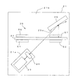
図1、図2は、本発明の実施形態の可変波長光源20の構造全体を示す図、図3、図4は、要部の構造を示している。
【0029】
図1、図2に示しているように、この可変波長光源20は、上面が互いに平行な高段部21aと低段部21bとを有する基台21と、基台21の高段部21aに固定されその上面に平行な光を出射するレーザ光源23、基台21の高段部21aに固定され、レーザ光源23から出射される光を平行光に変換するコリメートレンズ24、基台21の低段部21bに垂直に立てられた状態で固定され、コリメートレンズ24から出射される平行光を回折面25aで受ける回折格子25と、コリメートレンズ24と回折格子25の間の位置で基台21の低段部21b上に垂直に立てられたミラー一体型のアクチュエータ30とを有している。
【0030】
なお、回折格子25は、その回折面25aに設けられている回折溝(図示せず)が基台21の低段部21bの上面と直交する向きに固定されている。また、ここでは、コリメートレンズ24がレーザ光源23と独立に設けられている例を示すが、平行光を出射するレーザ光源を用いた場合には、コリメートレンズ24を省略することができる。
【0031】
アクチュエータ30は、コリメートレンズ24からの平行光を受けた回折格子25から出射される回折光を回折格子25側へ反射させ、その反射光に対する回折光を回折格子25からコリメートレンズ24を介してレーザ光源23に戻すための反射体と、その反射体を回折格子25に対して回動させるための機構とが一体的に形成されたものある。
【0032】
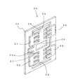
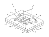
アクチュエータ30は、図3、図4に示しているように、導電性の高い薄い基板(例えば後述するSOI基板)に対するエッチング処理によって形成された1枚構造のアクチュエータ本体31と、アクチュエータ本体31の後述する可動板35に静電力を与えるための電極板51〜54、56〜59とを有している。
【0033】
アクチュエータ本体31は、基板32、連結部33、34および可動板35とによって構成されている。
【0034】
基板32は、互い平行な横長長方形の上板32aおよび下板32bと、上板32aと下板32bの左端間を上下に連結する略コの字形の左板32c、上板32aと下板32bの右端間を上下に連結する縦長長方形の右板32dとで、外形が長方形、内形が横向きの凸形に形成されており、下板32bの下側端面を基台21に当接させた状態で直立するように固定されている。
【0035】
連結部33は、基板32の上板32aの中央内縁から上板32aに直交するようにして下板32bの中央へ向かって所定幅で所定長さ延びている。
【0036】
また、連結部34は、基板32の下板32bの中央内縁から下板32bに直交するようにして上板32aの中央へ向かって所定幅で所定長さ延びている。
【0037】
ここで、連結部33、34の幅、厚さおよび長さは、連結部33、34自体が所定の角度範囲で捩じれ変形および傾き変形でき、その角度範囲内の変形に対して自ら元の状態に戻るための復帰力を生じるように設定されている。
【0038】
可動板35は、平板状で基板32の内形より小型な横向きの略凸状の外形を有し、連結部33、34を介して基板32の内側に面一状態で連結され、連結部33、34の捩じれ変形および傾き変形の可撓性により、基板32に対してその連結部33、34の延長線(この場合連結部33、34を結ぶ線)を中心とする回転および前後方向の移動が可能に形成されている。また、この可動板35の中央には、レーザ光源23と回折格子25の間を往復する光を通過させるための穴36が形成されている。
【0039】
また、この可動板35は、回折格子25からの回折光を反射するための反射体を形成するものであり、ここでは、可動板35のうち、少なくとも基板32の左板32cの切欠に隙間のある状態で進入している突出部35aの回折格子25側に向いた面の所定位置に、レーザ光を高い反射率で反射させる反射面37が形成されている。
【0040】
ただし、この反射面37は、基板32、連結部33、34および可動板35を含むアクチュエータ本体31の表面全体に形成されていてもよく、また、可動板35の表面全体だけに形成されていてもよい。
【0041】
また、反射面37としては、例えば、アクチュエータ本体31の表面全体あるいは可動板35の表面を鏡面仕上げしたり、高い反射率を示す金属膜を蒸着して形成したり、反射シートを貼付けて形成することができる。また、アクチュエータ本体31がレーザ光に対して高い反射率を示す材質である場合には、反射膜、や反射シートを設けなくても、その素材表面を反射面とすることができる。
【0042】
可動板35の上部左端、上部右端、下部左端、下部右端には、上下方向に所定間隔をもって複数本(ここでは3本)ずつ並び横方向に一定幅で所定長さ延びた櫛歯38〜41がそれぞれ形成されている。
【0043】
基板32の一面側の四隅には、電極板51〜54が絶縁板55を挟んで固定されている。各電極板51〜54には、可動板35の櫛歯38〜41にそれぞれ隙間のある状態で互いの隙間に入り込むことができるように形成された櫛歯51a〜54aがそれぞれ設けられている。
【0044】
また、基板32の反対面の四隅にも、それぞれ電極板56〜59が絶縁板55を挟んで固定されている。各電極板56〜59には、一面側の電極板51、54と同様に、可動板35の櫛歯38〜41にそれぞれ隙間のある状態で互いの隙間に入り込むことができるように形成された櫛歯56a〜59aがそれぞれ設けられている。
【0045】
このように構成されたアクチュエータ30は、コリメートレンズ24と回折格子25との間を結ぶ光路が可動板35の穴36を通過し、可動板35の回動中心(連結部33、34を結ぶ線)が回折格子25の回折面25aを延長した面上の位置となり、可動板35の一面側の反射面37が、回折格子25からの回折光をを受けて回折格子25側に反射させる位置で、基板32の下板32bの下縁が基台21の低段部21bの上に接した状態で垂直に立てられて固定されている。
【0046】
このアクチュエータ30では、基板32と各電極板との間に電圧を印加すると、基板32に連結部33、34を介して連続している可動板35の櫛歯38〜41と各電極板の櫛歯51a〜54a、56a〜59との間に電界が発生し、その電界の強さ(即ち印加電圧の大きさ)に応じた吸引方向の静電力を可動板35が受けて基板32に対する姿勢あるいは位置が変化する。
【0047】
例えば、図5の(a)に示しているように、基板32の電位を基準にして、前側左の電極板51、53に電圧Va(極性は任意)を印加し、その背面側の電極板56、58に電圧Vaより低い電圧Vbを印加すると、可動板35の左部は、電圧Vaに相当する前方への静電力と、電圧Vbに相当する後方への静電力とを受けるため、その差分の力で前方に移動する。また、同時に、前側右の電極板52、54に電圧Vbを印加し、その背面側の電極板57、59に電圧Vaを印加すれば、可動板35の右部は、電圧Vbに相当する前方への静電力と、電圧Vaに相当する後方への静電力とを受けるため、その差分の力で後方に移動する。
【0048】
したがって、図5の(a)のように電圧を印加した場合、可動板35全体は、その左側が前方に突出し右側が後方に突出する方向に連結部33、34を捩じれさせて連結部33、34を結ぶ線を中心に回動することになり、この捩じれに対する連結部33、34の復帰力と印加電圧による静電力とが釣り合った位置で停止することになり、回折格子25の回折面に対する反射面37の角度が変化する。
【0049】
このため、外部共振器の共振器長が変化して、レーザ光源23に戻る光の波長が変化し、回折格子25あるいはレーザ光源21の端面から出射されるレーザ光の波長が変化する。
【0050】
なお、上記のように可動板35を回動させるためには、基板32の電位を基準にして前側左の電極板51、53と背面側右の電極板57、59のみに電圧を印加すればよいが、このようにすると、可動板35を可動させようとする方向のみの力しか働かないので、可動板35が過渡的に振動してしまい所定位置に停止するまでに時間がかかってしまう。しかし、上記のように反対側から低い電圧で可動板35の回動を押さえる力を与えることで、この振動を小さくすることができ、所定位置に速やかに停止させる、即ち、ダンパとして使用している。
【0051】
また、図5の(b)のように、各電極に印加する電圧の大小関係を図5の(a)の場合と逆にすれば可動板35の角度を前記した場合と反対方向に所定角度回転させることができる。
【0052】
また、このアクチュエータ30では、可動板35全体を前後方向に移動させたり、可動板35の四隅部の少なくとも一カ所を前後方向に移動させることもできる。
【0053】
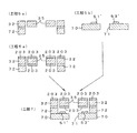
例えば、図6の(a)に示すように、基板32の電位を基準にして、前側の電極板51〜54に電圧Vaを印加し、背面側の電極板56〜59に電圧Vaより低い電圧Vbを印加すると、可動板35の四隅部は、電位差Va−Vbに相当する静電力を受けるため、可動板35全体は、連結部33、34を傾けさせて前方に移動することになり、この傾きに対する連結部33、34の復帰力と電位差による静電力とが釣り合った位置で停止することになり、回折格子25の回折面に対する反射面37の距離が変化する。
【0054】
また、図6の(b)のように、各電極板に印加する電圧の大小関係を逆にすれば、可動板35全体は、連結部33、34を傾けさせて後方に移動することになり、この傾きに対する連結部33、34の復帰力と電位差による静電力とが釣り合った位置で停止することになり、回折格子25の回折面に対する反射面37の距離が変化する。
【0055】
この可動板35の前後方向の移動は、反射面37の回動中心のずれを補正するために利用できる。
【0056】
即ち、上記回転動作例において、アクチュエータ本体31の厚さと反射面37を形成する部材の厚さ(0の場合もある)との合計が小さい場合には、反射面37の回転中心と可動板35の回転中心とはほぼ一致し、反射面37は、その反射面37を延長した面と回折格子25の回折面を延長した面とが交わる線を中心に回転することになり、レーザ光源23から出射される光の波長は回動板35の角度に追従して変化する。
【0057】
ただし、可動板35には厚さや反射面37を形成している部材の厚さとの合計が大きい場合、図7の(a)に示すように、可動板35の回転中心(即ち連結部33、34を結ぶ線の位置)Cと、反射面37を延長した面と回折格子25の回折面を延長した面とが交わる位置C′とは一致せず、可動板35の角度によって位置Cも移動してしまう。
【0058】
このような位置ずれが無視できない場合には、前記した電圧の印加により、可動板35全体の前後位置を調整すればよい。具体的には、可動板35の厚さ(基板32および連結部33、33の厚さも等しい)を2t、可動板35の表面から反射面37までの距離(反射材の厚さ)をα(α=0の場合もある)とすると、図7の(b)のように、可動板35全体をt+αだけ前方へ移動させる。この移動により、可動板35の回転中心Cと、反射面37を延長した面と回折格子25の回折面を延長した面とが交わる位置C′とを常に一致させることができる。
【0059】
また、前記した位置ずれだけでなく、アクチュエータ30自体の位置のずれ等も補正することができる。
【0060】
例えば、図8に示すように、アクチュエータ本体31が基台21の上に完全に垂直に立っておらずある角度θだけ傾いているような場合には、可動板35を基板32に対して定常的に角度θだけ傾けて基台21に垂直となる状態を維持したままで、波長の可変に必要な移動制御を行なえばよい。
【0061】
なお、実際にこのアクチュエータ30を制御する場合には、図9に示すように、これらの補正用の電圧分を含めて、予め所望波長λ(1)〜λ(n)について各電極板51〜54、56〜59に印加する最適な電圧を調べてその電圧データV(1,1)〜V(1,8)、V(2,1)〜V(2,8)、…、V(n,1)〜V(n,8)を各波長に対応付けてメモリ60に記憶しておき、波長λ(x)の指定を受けた制御部61が波長λ(x)に対応する各電圧データV(x,1)〜V(x,8)をメモリ60から読み出し、その電圧を各電極板51〜54、56〜59に印加すれば、この可変波長光源20から波長λ(x)の光を出射させることができる。
【0062】
次に、上記アクチュエータ30の製造方法の一例を図10に基づいて説明する。
【0063】
図10に示しているように、始めに、基板材料として導電率の高い活性層100aとベース基板100bとを絶縁層(SiO2)100cを挟んで貼り合わせたSOI(Silicon On Insulator)基板100を用意する(工程1)。
【0064】
そして、ICP−RIE(Inductively Coupled Plasma Reactive Ion Etching)装置によるエッチング処理ができるように、SOI基板100の活性層100aの表面のうち、アクチュエータ本体31の基板32、連結部33、34および可動板35の形成部分に、マスク101をフォトリソグラフィ技術を用いて形成する(工程2)。
【0065】
次に、ICP−RIE装置でマスク101に覆われていない活性層100aをエッチングして、アクチュエータ本体31の基板32、連結部33、34および可動板35を形成する(工程3)。
【0066】
次に、マスク101を除去して、その上に絶縁層(SiO2)102を挟んで、予め用意した導電性の高いシリコン基板103を貼り合わせる(工程4)。この貼り合わせには、アライメントの終了した2枚の鏡面仕上げされたシリコン基板に1200°Cの温度を加えて貼り付けるFusion Bondingの手法を用いている。
【0067】
次に、ベース基板100bの表面とシリコン基板103の表面のうち、電極板51〜54、56〜59の形成部分にマスク104を形成する(工程5)。
【0068】
そして、ICP−RIE装置でマスク104に覆われていないベース層100bおよびシリコン基板103をエッチングして、電極板51〜54、56〜59を形成する(工程6、工程7)。
【0069】
最後に、各電極板51〜54、56〜59に重なっていない絶縁層100c、102をエッチングで除去することで、アクチュエータ30が完成する(工程8)。
【0070】
なお、ここでは、シリコン基板の鏡面仕上げによって反射面を形成する場合を説明したが、鏡面仕上げをせずに、工程8の後に、少なくとも可動板35の表面に、反射率の高い金属膜を蒸着して反射面37を形成したり、反射シートを貼付けてもよい。
【0071】
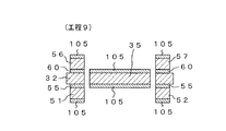
また、ここでは、導電率の高い基板100、103を用いてアクチュエータ30を製造する場合について説明したが、導電性の低い基板を用いた場合には、図10で示した工程1〜8の後に、図11の工程9のように、基板32と各電極板51〜54、56〜59の表面に導電率の高い金属膜105を蒸着して、基板32の可動板35と各電極板51〜54、56〜59との間に電界を印加できるようにする。また、金属膜105として反射率の高いものを用いれば、可動板35の反射面37を同時に形成することができる。
【0072】
このように実施形態の可変波長光源20では、アクチュエータ30の可動板35自体が回折格子25からの回折光を反射するための反射体を形成しているので、従来のように反射体をアクチュエータの可動部に垂直に固定する作業が不要となり、製造が極めて容易となる。
【0073】
また、可動板35は連結部33、34の捩じれ変形によって回転する構造で、その可変角度によらず回動中心の位置は一定であるため、大きな角度変化を与えることができ、波長の可変範囲が広くなるという効果がある。
【0074】
また、アクチュエータ30の可動板35がレーザ光源23と回折格子25の間の光路と交差する位置に固定され、可動板35には、レーザ光源23から回折格子25の間を往復する光を通過させるための窓36が形成されているので、レーザ光源23と回折格子25との距離を狭くしても、その間にアクチュエータ30を固定することができ、可変波長光源全体として小型に構成できる。
【0075】
また、電極板51〜54、56〜59の一部は櫛歯構造を有し、可動板35の縁部は電極板51〜54、56〜59の櫛歯の間に隙間をもって入り込む櫛歯37、38を有しているものでは、可動板35の回動範囲を狭くすることなく、アクチュエータ30全体の厚さを薄く形成できる。
【0076】
また、上記したアクチュエータ30のように、可動板35の回転中心に対して左右上下にそれぞれ独立した電極板51〜54、56〜59を設けたものでは、可動板35の回転制御だけでなく、左右上下についての前後方向の移動制御を独立に行なうことができ、回折格子25の回折面に対する距離の補正や基台21に対する傾きの補正等を含め、光学系全体の微妙な調整が可能となる。
【0077】
また、前記したアクチュエータ30は、可動板35を挟むように基板32の両面に電極板を設けていたが、図12、図13に示すアクチュエータ30Aのように、基板32のどちらか一方の面(図では、前面側を示すが背面側でもよい)に電極板51〜54を設けてもよい。
ただし、この場合には、基板32に対する可動板35の前後方向の移動は、その一方に限定される。
【0078】
また、図12、図13に示したアクチュエータ30Aをさらに簡素化して、左右のいずれか一方側の電極板(例えば左側の電極板51、53)のみで、可動板35を移動させるようにしてもよく、また、これをさらに簡素化して、図14、図15に示すアクチュエータ30Bのように、上下の電極板を一体化した電極板61を絶縁膜62を挟んで固定し、この電極板61のみで可動板35を回転させてもよい。ただし、この場合、基板32に対する可動板35の回転方向は一方に限定され、前後方向の移動制御はできないが、可動板35の反対側(右側)の櫛歯39、41を省略することができる。
【0079】
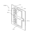
また、前記した各アクチュエータ30、30A、30Bでは、櫛歯構造の電極板を用いていたが、図16、図17に示すアクチュエータ30Cのように、外形が矩形の電極板51′〜54′が一面側にパターン形成され、中央部に光を通過させるための穴71が設けられた電極基板70を、アクチュエータ本体31の基板32と同形のスペーサ72を挟んで基板32の一面側に固定し、同様に、外形が矩形の電極板56′〜59′が一面側にパターン形成され、中央部に光を通過させるための穴74が設けられた電極基板73を、基板32と同形のスペーサ75を挟んで、基板32の反対面側に固定した構造であってもよい。なお、電極基板73の穴74は、回折格子25からの回折光を可動板35の突出部35に設けられた反射面37に受け入れるために、電極基板73の中央から側端近傍まで延びている。
【0080】
この場合、可動板35は、電極基板70、73で挟まれた領域内で姿勢や位置を変更することができ、前記同様にアクチュエータ本体30の電位を基準にして、各電極板51′〜54′、56′〜59′に電圧を印加することで、可動板35の四隅部に任意の静電力を与えて、その姿勢や位置を可変して波長を可変することができる。
【0081】
この場合には、スペーサ72、75の厚さ分だけアクチュエータ全体の厚さが増すが、可動板35および電極板51′〜54′、56′〜59′の構造が簡単化され製造が容易になる。
【0082】
また、このような矩形平板型の電極を用いたアクチュエータにおいても、櫛型の電極を用いた場合と同様に簡素化が可能であり、例えば図18および図19に示すアクチュエータ30Dのように、一方の電極基板70とスペーサ72のみを用いて構成してもよく、また、さらにその電極基板70の電極板52′、54′(または電極板51′、53′)を省略したり、あるいは、上下の電極板を一体化してもよい。
【0083】
ここで、この矩形平板型の電極を用いたアクチュエータ30Dの製造方法の一例を図20に基づいて説明する。
【0084】
図20に示しているように、始めに、基板材料として導電率が高く鏡面仕上げされた活性層200aとベース基板200bとを絶縁層(SiO2)200cを挟んで貼り合わせたSOI基板200を用意する(工程1a)。
【0085】
そして、ICP−RIE装置によるエッチング処理ができるように、SOI基板200の活性層200aの表面のうち、アクチュエータ本体31の基板32、連結部33、34および可動板35の形成部分にマスク201をフォトリソグラフィ技術を用いて形成し、ベース基板200bのうちスペーサ72の形成部分にもマスク202を形成にする(工程2a)。
【0086】
次に、ICP−RIE装置でマスク201に覆われていない活性層200aをエッチングして、アクチュエータ本体31の基板32、連結部33、34および可動板35を形成する(工程3a)。
【0087】
そして、マスク201を除去して、マスク202に覆われていないベース基板200bをエッチングして、スペーサ72を形成する(工程4a)。
次に、マスク202を除去し、絶縁層200cのうち、基板32とスペーサ72の間に挟まれている部分以外をエッチングによって除去する(工程5a)。なお、反射面を金属膜で形成する場合には、この段階でその処理を行なう。
【0088】
一方、電極基板70の材料となるガラス基板300を用意し(工程1b)、その表面全体に金属膜301を蒸着する(工程2b)。
【0089】
そして、この金属膜301のうち、電極板51′〜54′の形成部分にフォトレジストによってマスク302を形成し(工程3b)、金属膜301のうちマスク302で覆われていない部分をエッチングで除去し(工程4b)、さらに、穴71を貫通エッチングによって形成して、電極基板70を完成させる(工程5b)。
【0090】
そして、最後に、前記工程5aで得られたアクチュエータ本体31とスペーサ72とが一体的に形成されたものと、工程5bで形成された電極基板70とを陽極接合あるいは接着材によって貼り合わせて、アクチュエータ30を完成させる(工程6)。
【0091】
また、ここでは、導電率が高いSOI基板200を用いた製造例を示したが、前記したように導電率が低い基板を用いて構成することも可能である。
【0092】
その場合には、図20で示した工程1a〜5aの後に、図21に示すように、基板32の表面(下面側だけでもよい)に導電率の高い金属膜203を蒸着して(工程6a)、これと工程5bで形成された電極基板70とを陽極接合あるいは接着材によって貼り合わせて、アクチュエータ30を完成させる(工程7)。この金属膜203によって、基板32の可動板35と各電極板51′〜54′との間に電界を印加できる。また、この金属膜105として反射率の高いものを用い、図21に示しているように基板32の上面側にも蒸着しておけば、可動板35の反射面37を同時に形成することができる。
【0093】
なお、上記した各アクチュエータ本体は、基板32の形状を外形が矩形で内形が横向きの凸型にし、可動板35の形状も横向きの凸型にし、可動板35を上下2本の連結部33、34によって支持していたが、これらは本発明を限定するものではなく、基板および可動板の形状は任意であり、また、連結部を一つにしてもよい。
【0094】
例えば、図22の(a)のように、基板32の外形をコの字枠状に形成し、長方形の可動板35を上下の連結部33、34で支持することもできる。この場合、電極板としては、前記した電極基板の電極板を用いることが可能であり、また左側のみについては、前記した櫛歯構造の電極板を用いることができる。
【0095】
また、図22の(b)のように、基板32の外形を上向きのコの字枠状に形成し、長方形の可動板35を下側の連結部34のみで支持することもできる。この場合、電極板としては、前記した電極基板の電極板および櫛歯構造の電極板のいずれのものでも使用することができる。
【0096】
また、図22の(c)のように、基板32を横長の長方形にして、長方形の可動板35を下側の連結部34のみで支持することも可能である。この場合、電極板としては、前記した電極基板の電極板を用いることができる。
【0097】
【発明の効果】
以上説明したように、本発明の可変波長光源では、外部共振器型の可変波長光源において、回折格子からの回折光を反射するための反射体を移動させるアクチュエータとして、基板と、その基板の縁から直線状に延び、少なくとも捩じれ方向の可撓性を有する連結部と、この連結部を介して基板とほぼ面一の状態で連結され、連結部の可撓性により基板に対して少なくとも連結部の延長線を中心とする回転移動が可能で且つ一面側に回折格子からの回折光を反射させるための反射面が形成された可動板と、基板の少なくとも一面側に絶縁された状態で且つ一部が可動板の表面の縁部に隙間のある状態で対向する位置に固定され、可動板に静電力を与えるための電極板とを有し、可動板の反射面が回折格子からの回折光を受ける位置で基台に固定されている。
【0098】
このようにアクチュエータの可動板自体が反射体を形成しているので、従来のように反射体をアクチュエータの可動部に垂直に固定する作業が不要となり、製造が極めて容易となる。
【0099】
また、可動板は連結部の捩じれ変形によって回転する構造で、その可変角度によらず回動中心の位置は一定であるため、大きな角度変化を与えることができ、波長の可変範囲が広くなるという効果がある。
【0100】
また、アクチュエータの可動板がレーザ光源と回折格子の間の光路と交差する位置に固定され、可動板には、レーザ光源から回折格子の間を往復する光を通過させるための窓が形成されたものでは、アクチュエータをレーザ光源と回折格子の間に固定することができ、可変波長光源全体として小型に構成することができる。
【0101】
また、電極板の一部は櫛歯構造を有し、可動板の縁部は電極板の櫛歯の間に隙間をもって入り込む櫛歯を有しているものでは、可動板の回動範囲を狭くすることなく、アクチュエータ全体の厚さを薄く形成することができる。
【図面の簡単な説明】
【図1】本発明の実施形態の構成を示す斜視図
【図2】実施形態の平面図
【図3】実施形態の要部の斜視図
【図4】実施形態の要部の分解斜視図
【図5】可動板を回転させる場合の動作説明図
【図6】可動板を前後方向に移動させる場合の動作説明図
【図7】回転中心のずれに対する補正動作を説明するための図
【図8】アクチュエータの傾きに対する補正動作を説明するための図
【図9】制御部の構成を示す図
【図10】アクチュエータの製造工程例を示す図
【図11】アクチュエータの製造工程の変形例を示す図
【図12】変形したアクチュエータの斜視図
【図13】変形したアクチュエータの分解斜視図
【図14】変形したアクチュエータの斜視図
【図15】変形したアクチュエータの分解斜視図
【図16】矩形平板型の電極を用いたアクチュエータの斜視図
【図17】矩形平板型の電極を用いたアクチュエータの分解斜視図
【図18】変形したアクチュエータの斜視図
【図19】変形したアクチュエータの分解斜視図
【図20】矩形平板型の電極を用いたアクチュエータの製造工程例を示す図
【図21】矩形平板型の電極を用いたアクチュエータの製造工程の変形例を示す図
【図22】アクチュエータ本体の変形例を示す図
【図23】外部共振器型の可変波長光源の基本構成図
【図24】従来の可変波長光源の要部の構成例を示す斜視図
【図25】従来の可変波長光源の要部の平面図
【図26】図25のA−A線断面図
【図27】図25のB−B線断面図
【図28】従来の可変波長光源の要部の動作を説明するための図
【符号の説明】
20……可変波長光源、21……基台、23……レーザ光源、24……コリメートレンズ、25……回折格子、30、30A〜30D……アクチュエータ、31……アクチュエータ本体、32……基板、33、34……連結部、35……可動板、35a……突出部、36……穴、37……反射面、38〜41……櫛歯、51〜54、51′〜54′、56〜59、56′〜59′……電極板、51a〜54a、56a〜59a……櫛歯、55、60……絶縁膜、70、73……電極基板、71、74……穴、72、75……スペーサ[0001]
BACKGROUND OF THE INVENTION
The present invention relates to a technique for easily manufacturing an external resonator type variable wavelength light source and widening the wavelength variable range.
[0002]
[Prior art]
In recent years, with the widespread use of the Internet, traffic on communication lines has been steadily increasing, and the limit of transmission capacity has become a serious problem.
[0003]
As a technique for solving this problem, a WDM system that transmits a plurality of optical signals having different wavelengths using a single optical fiber has been developed and used in an actual communication line.
[0004]
In such a WDM communication line, a light source capable of arbitrarily setting a wavelength, that is, a variable wavelength light source is indispensable, and an external resonator type variable wavelength light source called a Litman type is well known as this type of variable wavelength light source. .
[0005]
The external resonator type variable wavelength light source basically has the structure shown in FIG.
The variable wavelength light source shown in FIG. 23 converts the light emitted from the
[0006]
In the variable wavelength light source having this structure, only the wavelength component orthogonal to the reflection surface of the
[0007]
This resonance wavelength is determined by the angle of the
[0008]
When an external resonator type variable wavelength light source having such a basic structure is actually used as a light source for a communication system, an actuator for rotating the
[0009]
In order to satisfy this requirement, conventionally, as shown in FIGS. 24 to 27, a flat-
[0010]
This
[0011]
A fan-
[0012]
The movable portion 11 extends in a narrow width from the narrower arc-shaped edge of the
[0013]
As shown in FIGS. 26 and 27, the movable portion 11 is supported in a state of being slightly lifted from the upper surface of the
[0014]
Fixed
[0015]
The
[0016]
Although the
[0017]
In the case of the
[0018]
The stop position of the movable portion 11 can be arbitrarily changed within a predetermined range by changing the applied voltage V.
[0019]
Therefore, as described above, if the
[0020]
[Patent Document 1]
International Publication No. 01/43241 Pamphlet
[0021]
[Problems to be solved by the invention]
However, as described above, the
[0022]
Further, since the movable portion 11 of the
[0023]
For this reason, there was a problem that a large angle change could not be given and the wavelength variable range was narrow.
[0024]
An object of the present invention is to solve this problem and provide a variable wavelength light source that is small in size, easy to manufacture, and has a wide wavelength variable range.
[0025]
[Means for Solving the Problems]
In order to achieve the object, a variable wavelength light source according to
Light emitted from a laser light source (23) fixed to a base (21) is incident on a diffraction grating (25) fixed to the base, and diffracted light emitted from the diffraction grating with respect to the incident light is emitted. The light is incident on the reflector (35) movable by the actuator (30), the reflected light reflected by the reflector is incident on the diffraction grating, and the diffracted light with respect to the reflected light is returned from the diffraction grating to the laser light source. In the external resonator type variable wavelength light source that varies the wavelength of the light emitted from the laser light source according to the change in the position of the reflector with respect to the diffraction grating,
The actuator is
A substrate (32) fixed to the base;
Connecting portions (33, 34) extending linearly from the edge of the substrate and having flexibility in at least the twisting direction;
It is connected to the substrate through the connecting portion so as to be substantially flush with the substrate, and due to the flexibility of the connecting portion, the substrate can be rotated around the extension line of the connecting portion at least on the one surface side. A movable plate (35) formed with a reflection surface (37) for reflecting diffracted light from the diffraction grating;
An electrode plate for applying an electrostatic force to the movable plate, which is fixed at a position that is insulated on at least one surface side of the substrate and a part thereof is opposed to the edge of the surface of the movable plate with a gap. 51-54, 56-59),
The reflecting surface of the movable plate receives the diffracted light from the diffraction grating. And the movable plate intersects an optical path between the laser light source and the diffraction grating. Fixed to the base at a position The movable plate is formed with a window (36) for allowing light reciprocating between the diffraction gratings from the laser light source to pass therethrough. It is characterized by that.
[0026]
The variable wavelength light source of
A part of the electrode plate has a comb-tooth structure, and an edge portion of the movable plate has a comb tooth that enters with a gap between the comb teeth of the electrode plate. It is characterized by that.
[0028]
DETAILED DESCRIPTION OF THE INVENTION
Hereinafter, embodiments of the present invention will be described with reference to the drawings.
1 and 2 are views showing the entire structure of a variable wavelength
[0029]
As shown in FIGS. 1 and 2, the variable wavelength
[0030]
The
[0031]
The
[0032]
As shown in FIGS. 3 and 4, the
[0033]
The
[0034]
The
[0035]
The connecting
[0036]
The connecting
[0037]
Here, the widths, thicknesses, and lengths of the connecting
[0038]
The
[0039]
In addition, the
[0040]
However, the
[0041]
Moreover, as the
[0042]
A plurality of comb teeth 38 (in this case three) are arranged at predetermined intervals in the vertical direction at the upper left end, the upper right end, the lower left end, and the lower right end of the
[0043]
[0044]
In addition,
[0045]
In the
[0046]
In this
[0047]
For example, as shown in FIG. 5A, the voltage Va (polarity is arbitrary) is applied to the front
[0048]
Therefore, when a voltage is applied as shown in FIG. 5A, the entire
[0049]
For this reason, the resonator length of the external resonator changes, the wavelength of the light returning to the
[0050]
In order to rotate the
[0051]
Further, as shown in FIG. 5B, if the magnitude relationship between the voltages applied to the respective electrodes is reversed to that in FIG. 5A, the angle of the
[0052]
In the
[0053]
For example, as shown in FIG. 6A, with reference to the potential of the
[0054]
Further, as shown in FIG. 6B, if the magnitude relation of the voltage applied to each electrode plate is reversed, the entire
[0055]
The movement of the
[0056]
That is, in the above rotation operation example, when the sum of the thickness of the actuator
[0057]
However, when the total thickness of the
[0058]
When such a positional shift cannot be ignored, the front and rear positions of the entire
[0059]
Further, not only the above-described positional deviation but also the positional deviation of the
[0060]
For example, as shown in FIG. 8, when the
[0061]
When the
[0062]
Next, an example of a method for manufacturing the
[0063]
As shown in FIG. 10, first, an active layer 100a having a high conductivity and a base substrate 100b are formed as an insulating layer (SiO 2) as a substrate material. 2 ) An SOI (Silicon On Insulator)
[0064]
Then, among the surfaces of the active layer 100a of the
[0065]
Next, the active layer 100a not covered with the
[0066]
Next, the
[0067]
Next, the
[0068]
Then, the base layer 100b and the
[0069]
Finally, the insulating
[0070]
Although the case where the reflective surface is formed by mirror finishing of the silicon substrate has been described here, a metal film having a high reflectance is vapor-deposited on at least the surface of the
[0071]
Here, the case where the
[0072]
As described above, in the variable wavelength
[0073]
In addition, the
[0074]
In addition, the
[0075]
Further, a part of the
[0076]
Further, in the case where the
[0077]
In the above-described
However, in this case, the movement of the
[0078]
Further, the
[0079]
Further, each of the
[0080]
In this case, the
[0081]
In this case, the thickness of the entire actuator is increased by the thickness of the
[0082]
In addition, in an actuator using such a rectangular flat plate type electrode, simplification is possible as in the case of using a comb type electrode. For example, like an actuator 30D shown in FIGS. The
[0083]
Here, an example of a manufacturing method of the actuator 30D using the rectangular plate type electrode will be described with reference to FIG.
[0084]
As shown in FIG. 20, first, an active layer 200a having a high conductivity and a mirror finish is used as a substrate material, and an insulating layer (
[0085]
Then, the
[0086]
Next, the active layer 200a not covered with the
[0087]
Then, the
Next, the
[0088]
On the other hand, the
[0089]
Then, in this
[0090]
Finally, the
[0091]
Although a manufacturing example using the
[0092]
In that case, after Steps 1a to 5a shown in FIG. 20, as shown in FIG. 21, a
[0093]
In each of the actuator bodies described above, the shape of the
[0094]
For example, as shown in FIG. 22A, the outer shape of the
[0095]
Further, as shown in FIG. 22B, the outer shape of the
[0096]
Further, as shown in FIG. 22C, the
[0097]
【The invention's effect】
As described above, in the variable wavelength light source of the present invention, in the external resonator type variable wavelength light source, as the actuator for moving the reflector for reflecting the diffracted light from the diffraction grating, the substrate and the edge of the substrate A connecting portion extending in a straight line and having flexibility in at least the torsional direction, and connected to the substrate in a substantially flush state via the connecting portion, and at least the connecting portion to the substrate due to the flexibility of the connecting portion A movable plate having a reflecting surface for reflecting the diffracted light from the diffraction grating on one surface side and being insulated on at least one surface side of the substrate. And an electrode plate for applying an electrostatic force to the movable plate, and the reflecting surface of the movable plate has a diffracted light from the diffraction grating. Fixed to the base It is.
[0098]
Since the movable plate of the actuator itself forms a reflector as described above, the work for fixing the reflector perpendicularly to the movable portion of the actuator as in the prior art becomes unnecessary, and the manufacturing becomes extremely easy.
[0099]
In addition, the movable plate is rotated by the torsional deformation of the connecting portion, and the position of the rotation center is constant regardless of the variable angle, so that a large angle change can be given, and the wavelength variable range is widened. effective.
[0100]
In addition, the movable plate of the actuator is fixed at a position that intersects the optical path between the laser light source and the diffraction grating, and a window is formed on the movable plate for passing light traveling back and forth between the laser light source and the diffraction grating. In the apparatus, the actuator can be fixed between the laser light source and the diffraction grating, and the entire variable wavelength light source can be made compact.
[0101]
In addition, a part of the electrode plate has a comb-tooth structure, and the edge of the movable plate has comb teeth that enter with a gap between the comb teeth of the electrode plate, the rotation range of the movable plate is narrowed. Therefore, the thickness of the entire actuator can be reduced.
[Brief description of the drawings]
FIG. 1 is a perspective view showing a configuration of an embodiment of the present invention.
FIG. 2 is a plan view of the embodiment.
FIG. 3 is a perspective view of a main part of the embodiment.
FIG. 4 is an exploded perspective view of a main part of the embodiment.
FIG. 5 is an operation explanatory diagram when rotating a movable plate.
FIG. 6 is an operation explanatory diagram when moving the movable plate in the front-rear direction.
FIG. 7 is a diagram for explaining a correction operation with respect to a rotation center shift;
FIG. 8 is a diagram for explaining a correction operation with respect to the tilt of the actuator;
FIG. 9 is a diagram showing a configuration of a control unit
FIG. 10 is a diagram illustrating an example of an actuator manufacturing process.
FIG. 11 is a diagram showing a modification of the manufacturing process of the actuator
FIG. 12 is a perspective view of a deformed actuator.
FIG. 13 is an exploded perspective view of a deformed actuator.
FIG. 14 is a perspective view of a deformed actuator.
FIG. 15 is an exploded perspective view of a deformed actuator.
FIG. 16 is a perspective view of an actuator using rectangular plate-type electrodes.
FIG. 17 is an exploded perspective view of an actuator using rectangular plate-type electrodes.
FIG. 18 is a perspective view of a deformed actuator.
FIG. 19 is an exploded perspective view of a deformed actuator.
FIG. 20 is a diagram showing an example of a manufacturing process of an actuator using a rectangular flat electrode.
FIG. 21 is a view showing a modification of the manufacturing process of the actuator using the rectangular flat plate type electrode.
FIG. 22 is a view showing a modified example of the actuator main body.
FIG. 23 is a basic configuration diagram of an external resonator type variable wavelength light source.
FIG. 24 is a perspective view showing a configuration example of a main part of a conventional variable wavelength light source.
FIG. 25 is a plan view of the main part of a conventional variable wavelength light source.
26 is a cross-sectional view taken along line AA in FIG.
27 is a sectional view taken along line BB in FIG.
FIG. 28 is a diagram for explaining the operation of the main part of a conventional variable wavelength light source;
[Explanation of symbols]
DESCRIPTION OF
Claims (2)
前記アクチュエータは、
前記基台に固定された基板(32)と、
前記基板の縁から直線状に延び、少なくとも捩じれ方向の可撓性を有する連結部(33、34)と、
前記連結部を介して前記基板とほぼ面一の状態で連結され、前記連結部の可撓性により前記基板に対して少なくとも前記連結部の延長線を中心とする回転移動が可能で且つ一面側に前記回折格子からの回折光を反射させるための反射面(37)が形成された可動板(35)と、
前記基板の少なくとも一面側に絶縁された状態で且つ一部が前記可動板の表面の縁部に隙間のある状態で対向する位置に固定され、前記可動板に静電力を与えるための電極板(51〜54、56〜59)とを有し、
前記可動板の反射面が前記回折格子からの回折光を受け、且つ前記可動板が前記レーザ光源と前記回折格子の間の光路と交差する位置で前記基台に固定され、前記可動板には、前記レーザ光源から前記回折格子の間を往復する光を通過させるための窓(36)が形成されていることを特徴とする可変波長光源。Light emitted from a laser light source (23) fixed to a base (21) is incident on a diffraction grating (25) fixed to the base, and diffracted light emitted from the diffraction grating with respect to the incident light is emitted. The light is incident on the reflector (35) movable by the actuator (30), the reflected light reflected by the reflector is incident on the diffraction grating, and the diffracted light with respect to the reflected light is returned from the diffraction grating to the laser light source. In the external resonator type variable wavelength light source that varies the wavelength of the light emitted from the laser light source according to the change in the position of the reflector with respect to the diffraction grating,
The actuator is
A substrate (32) fixed to the base;
Connecting portions (33, 34) extending linearly from the edge of the substrate and having flexibility in at least the twisting direction;
It is connected to the substrate through the connecting portion so as to be substantially flush with the substrate, and due to the flexibility of the connecting portion, the substrate can be rotated around the extension line of the connecting portion at least on the one surface side. A movable plate (35) formed with a reflection surface (37) for reflecting diffracted light from the diffraction grating;
An electrode plate for applying an electrostatic force to the movable plate, which is fixed at a position that is insulated on at least one surface side of the substrate and a part thereof is opposed to the edge of the surface of the movable plate with a gap. 51-54, 56-59),
The reflecting surface of the movable plate receives a diffracted light from the diffraction grating, fixed to the base and at the position you intersects the optical path between the movable plate of the diffraction grating and the laser light source, the movable plate Is a variable wavelength light source characterized in that a window (36) is formed for passing light reciprocating between the diffraction gratings from the laser light source.
Priority Applications (1)
| Application Number | Priority Date | Filing Date | Title |
|---|---|---|---|
| JP2002284995A JP3720008B2 (en) | 2002-09-30 | 2002-09-30 | Variable wavelength light source |
Applications Claiming Priority (1)
| Application Number | Priority Date | Filing Date | Title |
|---|---|---|---|
| JP2002284995A JP3720008B2 (en) | 2002-09-30 | 2002-09-30 | Variable wavelength light source |
Publications (3)
| Publication Number | Publication Date |
|---|---|
| JP2004119933A JP2004119933A (en) | 2004-04-15 |
| JP2004119933A5 JP2004119933A5 (en) | 2005-04-07 |
| JP3720008B2 true JP3720008B2 (en) | 2005-11-24 |
Family
ID=32278405
Family Applications (1)
| Application Number | Title | Priority Date | Filing Date |
|---|---|---|---|
| JP2002284995A Expired - Lifetime JP3720008B2 (en) | 2002-09-30 | 2002-09-30 | Variable wavelength light source |
Country Status (1)
| Country | Link |
|---|---|
| JP (1) | JP3720008B2 (en) |
Families Citing this family (3)
| Publication number | Priority date | Publication date | Assignee | Title |
|---|---|---|---|---|
| WO2008004664A1 (en) | 2006-07-06 | 2008-01-10 | Nikon Corporation | Micro actuator, optical unit, exposure device, and device manufacturing method |
| JP2010107628A (en) * | 2008-10-29 | 2010-05-13 | Topcon Corp | Mems scanning type mirror and method of manufacturing the same |
| JP2013029849A (en) * | 2012-09-14 | 2013-02-07 | Topcon Corp | Manufacturing method for mems scanning mirror |
-
2002
- 2002-09-30 JP JP2002284995A patent/JP3720008B2/en not_active Expired - Lifetime
Also Published As
| Publication number | Publication date |
|---|---|
| JP2004119933A (en) | 2004-04-15 |
Similar Documents
| Publication | Publication Date | Title |
|---|---|---|
| US7643520B2 (en) | External cavity resonator type tunable light source which can be easily manufactured and which is capable of wavelength sweeping at high speed | |
| WO2011161943A1 (en) | Optical reflection element | |
| US10288870B2 (en) | Wavelength tunable MEMS-Fabry Perot filter | |
| JP4416117B2 (en) | Deflection mirror, optical scanning device, and image forming apparatus | |
| CN110312944B (en) | MEMS scanning module for optical scanner | |
| TWI581004B (en) | Tunable optical device | |
| US20160356984A1 (en) | Optical element | |
| JP4473209B2 (en) | Variable wavelength optical filter | |
| JP2003215473A (en) | Fabry-perot filter | |
| JP5103412B2 (en) | Wavelength swept light source | |
| JP7683464B2 (en) | Optical device, distance measuring device and moving object | |
| JP3720008B2 (en) | Variable wavelength light source | |
| JP2005266074A (en) | Optical scanner | |
| US20060039060A1 (en) | Scanning device and fabrication method thereof | |
| JP2003057438A (en) | Fabry-perot filter | |
| JP5002757B2 (en) | Light wavefront control device | |
| JP2001033727A (en) | Light deflector | |
| JP3761869B2 (en) | Optical scanner | |
| JP2001264676A (en) | Optical scanner | |
| JP4559744B2 (en) | Comb-shaped actuator and light control element | |
| JP2006133412A (en) | Spatial optical modulation element | |
| JP2005205578A (en) | Comb-shaped actuator | |
| WO2019009398A1 (en) | Optical device | |
| JP2001272626A (en) | Optical scanner | |
| JP2009139546A (en) | Variable wavelength light source |
Legal Events
| Date | Code | Title | Description |
|---|---|---|---|
| A521 | Written amendment |
Free format text: JAPANESE INTERMEDIATE CODE: A523 Effective date: 20040426 |
|
| A977 | Report on retrieval |
Free format text: JAPANESE INTERMEDIATE CODE: A971007 Effective date: 20050517 |
|
| A131 | Notification of reasons for refusal |
Free format text: JAPANESE INTERMEDIATE CODE: A131 Effective date: 20050524 |
|
| A521 | Written amendment |
Free format text: JAPANESE INTERMEDIATE CODE: A523 Effective date: 20050725 |
|
| TRDD | Decision of grant or rejection written | ||
| A01 | Written decision to grant a patent or to grant a registration (utility model) |
Free format text: JAPANESE INTERMEDIATE CODE: A01 Effective date: 20050816 |
|
| A61 | First payment of annual fees (during grant procedure) |
Free format text: JAPANESE INTERMEDIATE CODE: A61 Effective date: 20050906 |
|
| R150 | Certificate of patent or registration of utility model |
Free format text: JAPANESE INTERMEDIATE CODE: R150 |
|
| S531 | Written request for registration of change of domicile |
Free format text: JAPANESE INTERMEDIATE CODE: R313532 |
|
| R350 | Written notification of registration of transfer |
Free format text: JAPANESE INTERMEDIATE CODE: R350 |
|
| FPAY | Renewal fee payment (event date is renewal date of database) |
Free format text: PAYMENT UNTIL: 20080916 Year of fee payment: 3 |
|
| FPAY | Renewal fee payment (event date is renewal date of database) |
Free format text: PAYMENT UNTIL: 20090916 Year of fee payment: 4 |
|
| FPAY | Renewal fee payment (event date is renewal date of database) |
Free format text: PAYMENT UNTIL: 20090916 Year of fee payment: 4 |
|
| FPAY | Renewal fee payment (event date is renewal date of database) |
Free format text: PAYMENT UNTIL: 20100916 Year of fee payment: 5 |
|
| FPAY | Renewal fee payment (event date is renewal date of database) |
Free format text: PAYMENT UNTIL: 20110916 Year of fee payment: 6 |
|
| FPAY | Renewal fee payment (event date is renewal date of database) |
Free format text: PAYMENT UNTIL: 20120916 Year of fee payment: 7 |

