JP3718552B2 - Tractor speed change mechanism - Google Patents
Tractor speed change mechanism Download PDFInfo
- Publication number
- JP3718552B2 JP3718552B2 JP03105796A JP3105796A JP3718552B2 JP 3718552 B2 JP3718552 B2 JP 3718552B2 JP 03105796 A JP03105796 A JP 03105796A JP 3105796 A JP3105796 A JP 3105796A JP 3718552 B2 JP3718552 B2 JP 3718552B2
- Authority
- JP
- Japan
- Prior art keywords
- transmission
- shift
- lever
- cabin
- shaft
- Prior art date
- Legal status (The legal status is an assumption and is not a legal conclusion. Google has not performed a legal analysis and makes no representation as to the accuracy of the status listed.)
- Expired - Fee Related
Links
- 230000005540 biological transmission Effects 0.000 claims description 110
- 230000007935 neutral effect Effects 0.000 claims description 8
- 230000033001 locomotion Effects 0.000 description 8
- 239000003921 oil Substances 0.000 description 5
- 240000001973 Ficus microcarpa Species 0.000 description 3
- 238000010586 diagram Methods 0.000 description 3
- 238000000034 method Methods 0.000 description 3
- 230000000694 effects Effects 0.000 description 2
- 239000010687 lubricating oil Substances 0.000 description 2
- 238000012423 maintenance Methods 0.000 description 2
- 230000007257 malfunction Effects 0.000 description 1
- 238000005192 partition Methods 0.000 description 1
- 238000000638 solvent extraction Methods 0.000 description 1
Images


Landscapes
- Arrangement Or Mounting Of Control Devices For Change-Speed Gearing (AREA)
Description
【0001】
【発明の属する技術分野】
本発明は、トラクタにおいて、不整地を走行する場合に発生する振動や上下動に対して、各部の部品間の連結部が抜けたり、外れたりすることの無いように、抜け止めをする機構に関する。
【0002】
【従来の技術】
従来から、トラクタ及びトラクタの変速操作レバー機構において、ステアリングハンドルの部分に変速レバーを設けて、変速操作を可能とした技術は公知とされている。例えば、実公平3−1653号公報に記載の技術の如くである。
【0003】
【発明が解決しようとする課題】
本発明は、2つの部品を、デテント機構ボルト、又はピン等を介装するという簡単な構成により、以下の課題を解決しようとするものである。
最近のトラクタは、運転席の周囲をキャビンで被覆することが多くなり、キャビンをトラクタの機体に対して、防振ゴムにより振動の少ない状態に支持するのである。
防振性能をより向上する為に、またキャビン内の騒音を低減させる為に、防振ゴムが従来のものよりも、更に柔らかいものを使用する傾向となった。
【0004】
その為に、トラクタが不整地を走行すると、キャビンがトラクタのミッションケースに対して大きく振動し、ミッションケース内の変速機構とリジッドに連結されており、かつ操作支点がキャビンの側に設けられている変速レバーのリンクの部分が、キャビンの振動や揺動の巾が大きくなった分だけ、レバーの動き量が増加し、キャビンの振動や揺動に対して、バタツキを発生するのである。
【0005】
これにより、変速レバーの部分が見た目も悪くなり、時にはハンドルとレバーとの間で、手を挟むこともある為に、このキャビンの揺れに対して、振動しないレバーリンクを考えることにより、快適な操作空間の改善に繋がるのである。
本発明は、この不具合を改善する為に、ミッションケース内の遊び分は、リンクシャフトをキャビンの動きに連動させて、そのレバーの揺れを低減させるものである。
【0006】
【課題を解決するための手段】
本発明の解決しようとする課題は上記の如くであり、次に該課題を解決するための手段を説明する。
請求項1においては、ミッションケースMの上方に防振ゴムHを介してキャビンCを搭載し、該キャビンCの内部に、キャビンCと一体化したステアリングコラム5により、変速レバー1の操作で上下動しかつ回動を行なう変速シャフト4を枢支し、前記ミッションケースMの内部に、変速摺動ギヤを摺動させる変速シフター係合部13・14を上下に配置し、前記変速シャフト4に連動したシフター回動アーム15が、該変速シフター係合部13・14のどちらかに係合し回動されて変速を行う構成において、該変速シャフト4とステアリングコラム5との間にデテント機構を構成し、該デテント機構は、該変速シャフト4の円周上に周溝状に穿設されたデテント溝22と、該デテント溝22から上方へ分岐穿設された縦溝18とに、前記ステアリングコラム5の側のボール17が嵌入すべく構成し、前記縦溝18は中立位置であり、該ボール17がデテント溝22に嵌入する位置と、縦溝18の他端部にボール17が至った位置が、シフター回動アーム15が変速シフター係合部13・14に係合する位置としたものである。
【0007】
請求項2においては、請求項1記載のトラクタの変速機構において、該変速シャフト4の外周で、前記ステアリングコラム5の上端と下端に、スプリング11・12を介装したものである。
【0008】
請求項3においては、請求項1記載のトラクタの変速機構において、変速レバー1は『コ』の字型に構成されたレバー基部アーム3と一体的に構成され、該レバー基部アーム3のステアリングハンドルS側が上下回動軸6により、キャビンCの側に枢支され、該レバー基部アーム3にシフトブロック2を枢支ピン10を介して枢支し、該シフトブロック2に対して変速シャフト4を枢支ピン7を介して枢支し、該枢支ピン10と枢支ピン7の位置とをオフセットさせたものである。
【0009】
【発明の実施の形態】
次に本発明の実施の形態を説明する。
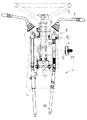
図1はキャビンCを搭載したトラクタの全体側面図、図2はキャビンCとミッションケースMと、両者の間を連結する変速リンク機構Lの全体的な配置を示す図面、図3は変速リンク機構LとステアリングハンドルSの部分の正面図である。
【0010】
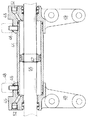
図4は変速リンク機構Lの側面図、図5は変速リンク機構Lの分解状態の斜視図、図6は変速リンク機構Lの従来の構造を示す分解状態の斜視図、図7R>7は本発明の変速レバー1の支持部を示す平面図である。
【0011】
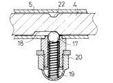
図8は変速リンク機構Lに設けたデテント機構の拡大正面断面図、図9は変速シャフト4の拡大側面図、図10はミッションケースM内の変速シフター軸23・24や変速シフター係合部13・14の部分の拡大側面図である。
【0012】
図11は変速レバー1の部分の枢支部に伸縮弾性体11を介装した実施例の側面図、図12は変速レバー1の枢支位置を偏心した構成の作用を示す図面である。
【0013】
図1において説明する。
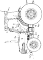
図1はキャビンCを搭載したトラクタの全体側面図を示している。前輪FWと後輪RWにより、クラッチハウジングCHとミッションケースMを支持している。クラッチハウジングCHの上部にボンネットBを載置し、該ボンネットBの上面をボンネットカバーBaで被覆している。
【0014】
キャビンCは、ミッションケースMと後輪RWの上方に、防振ゴムHを介して支持している。該防振ゴムHを、騒音レベル低下の為に柔らかいものとしているので、トラクタの機体が不整地で振動すると、キャビンCが大きく振動・揺動するのである。
図1において、Sはステアリングハンドル、DBはエアコンディショナーの吐出口である。
【0015】
図2はミッションケースMとキャビンCと変速リンク機構Lとの関係位置を示す側面図である。ミッションケースMの内部に変速ギヤ機構が配置されており、該変速摺動ギヤを摺動させる変速シフター軸23・24が配置されている。該変速シフター軸23・24より、変速3・4速用の変速シフター係合部13と、変速1・2速の変速シフター係合部14が突設されており、このどちらかに嵌入するようにシフター回動アーム15が設けられている。該シフター回動アーム15が、変速シフター係合部13・14のどちらかに係合して回動されて、変速シフター軸23・24のどちらかを摺動させて、他方はそのままの位置に保持する必要がある。
【0016】
しかし、図10において図示する如く、このシフター回動アーム15が一方の変速シフ ター係合部13・14に嵌合し、他方の変速シフター係合部13・14に係合しない、間隙t1,t2を構成し、変速リンク機構Lや変速レバー1が、キャビンCやステアリングコラム5と共に上下動した場合にも、変速3・4速用の変速シフター係合部13と変速1・2速の変速シフター係合部14の間で、変速誤操作が発生しないように構成している。
【0017】
従来の技術は、図6に図示する如く、変速レバー1から回動リンク16までの変速リンク機構Lが構成されていたのである。即ち、変速レバー1が、変速シャフト34にピンにより枢結されて、更に変速シャフト34がステアリングコラム35にピンにより枢結されていた。該変速シャフト34の下方に、回動リンク16が連結されていたのである。
【0018】
故に、変速レバー1とシフター回動アーム15との間は、上下動を吸収できるようなガタが設けられていなかったのである。また、変速3・4速用の変速シフター係合部13や変速1・2速の変速シフター係合部14と、シフター回動アーム15の間においても、本発明の間隙t1,t2のような、許容間隙が構成されていなかったのである。
本発明はこのように、キャビンCが大きく振動する場合に、この間隙t1,t2以上には、シフター回動アーム15が振動しないが、該間隙t1,t2以下の振動で、変速リンク機構Lや変速レバー1が、キャビンCやステアリングコラム5と共に共振するように、デテント機構やスプリング11を構成したものである。該シフター回動アーム15は、変速リンク機構Lから下方に伸びる回動リンク16により上下動と回動操作をされる。
【0019】
本発明は図5に示す如く構成することにより、上記の不具合を解消したものである。
即ち、ボール17により構成したボールデテント機構を、変速シャフト4を受けるステアリングコラム5の部分に設けたものである。そして、変速シャフト4に縦溝18を設けて、この位置が変速レバー1の中立位置であることを判り易くしている。
【0020】
また、変速レバー1を下方向に引っ張る際の受け部分にスプリング11を介装している。また、ステアリングコラム5の内部で変速シャフト4を引き上げ、引下げするのに、シフトブロック2を用いている。該シフトブロック2がオフセットした位置を、変速レバー1により上下させて、変速レバー1の動く角度を、図12に示す如く、減少させているのである。また、ボール17のデテントスプリング19を組み付ける構造として、袋ナット20により簡単に組み付け可能としている。
【0021】
図7において、変速レバー1とレバー基部アーム3の構成を説明する。該変速レバー1は『コ』の字型に構成されたレバー基部アーム3の上面に基部板3aの部分で溶接されて、変速レバー1と基部板3aとレバー基部アーム3が一体的に構成されている。該レバー基部アーム3のステアリングハンドルS側が、『ハ』の字型に開いており、該部分に架設して上下回動軸6が固定されている。該上下回動軸6は摺動枢支カラー30の内部に前後に摺動可能に枢支されている。
【0022】
そして該摺動枢支カラー30が、キャビンCと一体的に構成されたステアリングハンドルSの部分の枢支ブラケット33に嵌装されて、変速レバー1を上下に回動して、変速1・2速と、変速3・4速の切換の際の回動中心を構成している。
さらに上下に変速レバー1を回動した位置で、変速レバー1を前後に回動することにより、変速1速と2速、又は変速3速と4速の切換を行なうのであるが、この為に変速レバー1を前後回動した場合の回動の中心は、ステアリングコラム5内に変速シャフト4を遊嵌した部分の軸心である。
故に、変速レバー1の回動に際して、レバー基部アーム3の先端の上下回動軸6の部分が摺動枢支カラー30の内部で前後に摺動して、該変速レバー1の前後回動を許容している。
【0023】
そして、変速レバー1の上下回動により、変速シャフト4の上下動を行なうのであるが、従来は、図6に示す如く、変速シャフト34の上端の中心位置に、枢支ピン10が嵌装されていたので、前記上下回動軸6の中心と、枢支ピン10の中心の距離が、図12の距離T1の如く、短かったのである。
故に、距離T1が短い位置で、キャビンCの振動幅dが発生すると、該振動幅dが、そのまま、変速レバー1の先端まで拡大されて伝達され、変速レバー1の上下振動幅が角度Rと大きかったのである。
【0024】
本発明においては、キャビンCの振動幅dがあっても、変速レバー1の先端の振動幅は小にすべく、変速シャフト4の中心位置と枢支ピン10の位置とを、オフセットしたものである。その為にシフトブロック2の長さも長くなり、シフトブロック2に対して変速シャフト4を枢支する枢支ピン7と、シフトブロック2をレバー基部アーム3に枢支する枢支ピン10とを別に構成しているのである。そして、該枢支ピン10と枢支ピン7との距離を設けて、オフセット状態を構成している。
【0025】
即ち、オフセットの幅を付加した、枢支ピン10と上下回動軸6との距離は、距離T2となり、該距離T2の位置で、キャビンCが振動幅dだけ振動しても、変速レバー1の先端における振動幅は、角度R’と小さく押さえることが出来るのである。
【0026】
また、キャビンCが振動幅dで振動しても、変速シャフト4や変速レバー1も同じくキャビンCやステアリングコラム5と共に、上下に振動すれば、変速レバー1がキャビンCと逆の方向に、ガタゴトと振動するという不具合を解消することが出来るのである。
本発明においては、キャビンCが振動した場合に、変速シャフト4や変速レバー1やシフトブロック2と共に、キャビンCの振動と共振するように、デテント機構をステアリングコラム5と変速シャフト4の間に介装したものである。
【0027】
従来は、図6に示す如く、変速シャフト34とステアリングコラム35の間にはデテント機構が設けられていなかったのである。故に、ステアリングコラム5はステアリングハンドルSは、キャビンCと共に振動するのに対して、変速シャフト34や変速レバー1やレバー基部アーム3やシフトブロック2は、ミッションケースMの側で、それほど振動しないので、故に、キャビンCの振動とは逆の方向に変速レバー1が振動するという不具合があったのである。
本発明は、この不具合を解消すべく、ボール17とデテントスプリング19のデテント機構をステアリングコラム5に設けている。
【0028】
変速シャフト4の円周上に、周溝状に構成されたデテント溝22が穿設されている。また該デテント溝22から上方へ、縦溝18が分岐穿設されている。そしてデテント機構のボール17が、デテント溝22に嵌入するのは、変速レバー1を上方へ回動して、シフター回動アーム15が、変速3・4速用の変速シフター係合部13に嵌入する場合である。
このように、変速レバー1が摺動枢支カラー30を中心に上方へ引き上げられた状態では、変速シャフト4がステアリングコラム5内で上方へ引き揚げられて、ボール17はデテント溝22の部分に位置する。
【0029】
このボール17がデテント溝22の部分に位置した状態で、変速レバー1を前後に回動すると、変速シャフト4のデテント溝22にボール17が嵌入した位置で、変速シャフト4のデテント溝22の部分がボール17に対して、周囲の溝を通過させる構成となる。
そして、シフター回動アーム15を変速1・2速の変速シフター係合部14に切換える場合には、変速レバー1を中立の位置に戻すのである。該変速レバー1の前後への回動角は約25度程度であり、前後約50度の幅の中央の25度の位置まで回動し戻すと、中立溝である縦溝18に至る。
【0030】
該縦溝18の位置で、変速レバー1を下方へ回動すると、ボール17に対して、縦溝18の上下する状態が発生し、縦溝18の端部にボール17が至った位置が、変速1・2速の変速シフター係合部14にシフター回動アーム15が係合した位置である。このように、変速1・2速の変速シフター係合部14に嵌合した状態では、変速シャフト4とシフトブロック2の間に介装されたスプリング11が、押圧された状態となっている。
【0031】
該位置で、変速レバー1を前後に回動すると、縦溝18の端部に位置していたボール17が押しこまれて、変速シャフト4の溝でない部分に乗り上げる。このボール17が外周に乗り上げた状態で、ボール17が変速シャフト4を押圧することにより、変速シャフト4とステアリングコラム5との一体化が成されており、キャビンCの振動に呼応して、変速シャフト4や変速レバー1も上下に共振することとなり、変速レバー1独自の上下振動は無くなるのである。該変速1・2速の変速シフター係合部14の変速位置から、また25度回動すると中立位置に戻り、ボール17は縦溝18の中に嵌入して、変速レバー1の中立位置が確認できる。このボール17が縦溝18に嵌入した状態で、変速レバー1は上下回動軸6を中心に上下に回動可能である。
【0032】
本発明においては、変速シャフト4の外周で、ステアリングコラム5の上端とシフトブロック2との間に、スプリング11を介装しており、これにより、キャビンCの上下動により、シフトブロック2が一気に下降して、キャビンCと一体化されているステアリングコラム5の状態と、シフトブロック2の下端か緩衝しあうことにより発生する、両者の破損を、スプリング11により阻止している。また、ステアリングコラム5の下端で、変速シャフト4の外周にも、スプリング12を介装して、変速シャフト4とステアリングコラム5との自由な上下動を、スプリング11と12で牽制している。
【0033】
次に図13において、フロントギヤケースKとステアリングギヤケースGの間の抜け止め構成について説明する。
図13はフロントギヤケースKに対してステアリングギヤケースGの抜け止めをボルトにより構成した実施例の正面断面図である。従来から、前輪駆動式トラクタにおいて、前輪を操向回動可能とする為に、フロントギヤケースとステアリングギヤケースとの間を回動可能に枢支し、抜け止め機構を配置した技術は公知とされているのである。例えば、特開平5−294154号公報に記載の如くである。
【0034】
トラクタの前輪駆動装置のステアリングギアケースの回動部分において、フロントギヤケースKからステアリングギヤケースGが抜け落ちることの無いように、簡単な抜け止め構成を抜け止めボルト9により構成し、ステアリングギヤケースGの内部に配置したものである。ステアリングギヤケースG内に抜け止めを行なったことにより、潤滑油の漏れ出しの危険性が無くなり、構造が簡単で、組立やメンテナンス性能の向上が図れるのである。
【0035】
本構成は、前輪駆動型のトラクタにおいて、前輪FWの操向回動を可能とすべく、フロントギヤケースKとステアリングギヤケースGの間で、キングピン29の周囲に回動可能に枢支した構成において、フロントギヤケースKに対してステアリングギヤケースGの抜け止めを行なう抜け止めボルト9を、ステアリングギヤケースGの内部で、フロントギヤケースKの外周に嵌装したものである。該フロントギヤケースKは、フロントデフケースの部分から、左右の前輪FWに向けて突出されている部分である。該フロントギヤケースKの部分は、左右前輪が別々に不整地に乗り上げた場合の為に、センターピンを中心に、左右の両側が上下に回動はするが、操向回動の為に前輪FWと共に、左右に回動することは不可能とされている。
【0036】
該フロントギヤケースKの下端に、キングピン29を中心に回動可能に、ステアリングギヤケースGが枢支されている。そして、フロントギヤケースKの軸28からの回転が、前輪駆動軸23にベベルギアを介して伝達されている。即ち、軸28からベベルギア27に動力伝達され、該ベベルギア27がキングピン29のベベルギア26と噛合している。該ベベルギア26からキングピン29を介して、ベベルギア25に動力伝達される。次に該ベベルギア25が、ステアリングギヤケースG内の変速24と噛合されており、ベベルギア24に前輪駆動軸23が固定されている。
【0037】
そして、キングピン29は、フロントギヤケースKに対して軸受39で支持されて、ステアリングギヤケースGに対して、軸受42で枢支されている。また、ステアリングギヤケースGは、該フロントギヤケースKに対して、軸受37と38で枢支され、該フロントギヤケースKとキングピン29の中心の周囲を、ステアリングの為に回動可能としている。また前輪駆動軸23は、ステアリングギヤケースGに対して、軸受40と41で支持されている。
【0038】
これに対して、本発明においては、ステアリングギヤケースGの内部に抜け止めボルト9を設けて、該抜け止めボルト9を軸受37の内周に当てて、該抜け止めボルト9は、フロントギヤケースKの外周に螺装することにより、フロントギヤケースKとステアリングギヤケースGの抜け止めとしているのである。因みに該軸受37の外周がフロントギヤケースKに嵌装されている。
【0039】
前輪駆動型のトラクタにおいて、前輪FWの操向回動を可能とすべく、フロントギヤケースKとステアリングギヤケースGの間で、キングピン29の周囲に回動可能に枢支した構成において、フロントギヤケースKに対してステアリングギヤケースGの抜け止めを行なう抜け止めボルト9を、ステアリングギヤケースGの内部で、フロントギヤケースKの外周に嵌装したので、フロントギヤケースKからステアリングギヤケースGが抜け落ちることの無いような抜け止めボルト9の構成を簡単な構成とすることが出来たのである。また、ステアリングギヤケースGの内部に抜け止めボルト9を設けたことにより、潤滑油の漏れ出しの危険性が無くなり、構造が簡単で、組立やメンテナンス性能の向上が図れるのである。
【0040】
次に、油圧式ステアリング装置Uの抜け止め構成について説明する。
図14は油圧式ステアリング装置Uの油圧シリンダ部分の平面図、図15は同じく油圧式ステアリング装置Uの側面図、図16は油圧式ステアリング装置Uのシリンダ部の拡大断面図である。
トラクタの油圧式操向装置を構成する油圧シリンダの部分において、オイルシールやブッシュを組み付けたシリンダキャップは、油圧式操向装置の配管のオイルポートを有すると同時に、フロントアクスルへの取付ステーも兼ねる。このシリンダキャップの部分の抜け止め機構を、メンテナンス性が良好で、かつ、コストの安い構成としたものである。
従来は、特開平5−294154号公報に記載の如く、軸受の上下に設けた止め輪により抜け止めとしていたのである。
【0041】
本構成においては、油圧式ステアリング装置Uを具備したトラクタにおいて、該油圧式ステアリング装置Uの油圧シリンダを両ロッド式とし、該両ロッドの油圧シリンダ44を、フロントデフケース50に固定する構造において、油圧シリンダ44の両側に摺動油密体45を設け、該摺動油密体45を油圧シリンダ44に対して、抜け止めピン46で固定し、該摺動油密体45をフロントデフケース50に固定したものである。
【0042】
油圧式ステアリング装置Uの油圧シリンダを、両ロッド式とした場合においては、該油圧シリンダ44の部分を、トラクタの前輪駆動部を構成するフロントデフケース50等に固定する必要がある。従来は、該フロントデフケース50への油圧シリンダ44の固定部分は、別に固定ブラケットを構成して、これにより、油圧シリンダ44の外周を抱持して、フロントデフケース50に固定ブラケットを固定することにより、係止固定していた。
【0043】
また、両ロッドの油圧シリンダの油圧シリンダ44の両端とピストン55との間の油密部を構成する摺動油密体を、油圧シリンダ44の内側に嵌入して、止め輪等により、油圧シリンダ44と摺動油密体とを固定していたのである。これに対して、本発明においては、摺動油密体45を剛体に構成して、これを、油圧シリンダ44の外周に嵌装して、抜け止めピン46により油圧シリンダ44と摺動油密体45とを一体化し、該摺動油密体45自体を、フロントデフケース50と油圧シリンダとの固定体として兼用したものである。
【0044】
また、該摺動油密体45は、油圧式ステアリング装置Uのバルブからの油圧配管51を連結する配管継手孔52をも開口して、該摺動油密体45自体に配管継手体も兼用させているのである。47は両ロッドの油圧シリンダの内部を仕切り仕切り壁であり、ピストン55の側に、止め輪により係止されている。
【0045】
油圧式ステアリング装置Uを具備したトラクタにおいて、該油圧式ステアリング装置Uの油圧シリンダを両ロッド式とし、該両ロッドの油圧シリンダ44を、フロントデフケース50に固定する構造において、油圧シリンダ44の両側に摺動油密体45を設け、該摺動油密体45を油圧シリンダ44に対して、抜け止めピン46で固定し、該摺動油密体45をフロントデフケース50に固定したので、オイルシールやブッシュを組み付けたシリンダキャップは、油圧式操向装置の配管のオイルポートを有すると同時に、フロントアクスルへの取付ステーも兼用させることが出来たのである。このシリンダキャップの部分の抜け止め機構を、メンテナンス性が良好で、コストの安い構成とすることが出来たのである。
【0046】
【発明の効果】
本発明は以上の如く構成したので、次のような効果を奏するのである。
請求項1の如く、ミッションケースMの上方に防振ゴムHを介してキャビンCを搭載し、該キャビンCの内部に、キャビンCと一体化したステアリングコラム5により、変速レバー1の操作で上下動しかつ回動を行なう変速シャフト4を枢支し、前記ミッションケースMの内部に、変速摺動ギヤを摺動させる変速シフター係合部13・14を上下に配置し、前記変速シャフト4に連動したシフター回動アーム15が、該変速シフター係合部13・14のどちらかに係合し回動されて変速を行う構成において、該変速シャフト4とステアリングコラム5との間にデテント機構を構成し、該デテント機構は、該変速シャフト4の円周上に周溝状に穿設されたデテント溝22と、該デテント溝22から上方へ分岐穿設された縦溝18とに、前記ステアリングコラム5の側のボール17が嵌入すべく構成し、前記縦溝18は中立位置であり、該ボール17がデテント溝22に嵌入する位置と、縦溝18の他端部にボール17が至った位置が、シフター回動アーム15が変速シフター係合部13・14に係合する位置としたので、防振ゴムHが柔らかい為に、キャビンCがトラクタの本機に対して、大きく振動揺動する場合において、変速レバー1と変速リンク機構LがミッションケースM側に係合され、ステアリングコラム5の側がキャビンCの側に固定されている為に発生する、変速レバー1の上下へのバタツキを、無くすことが出来るのである。
即ち、変速リンク機構Lと変速レバー1を、変速シフター係合部13・14に対して、間隙t1,t2だけ上下動を許容する構成として、デテント機構により、変速リンク機構Lや変速レバー1がステアリングコラム5やキャビンCと共に上下共振を可能としたことにより、変速レバー1の誤作動を無くすことが出来たのである。
【0047】
請求項2の如く、請求項1記載のトラクタの変速機構において、該変速シャフト4の外周で、前記ステアリングコラム5の上端と下端に、スプリング11・12を介装したので、キャビンCの振動により、シフトブロック2がステアリングコラム5に衝撃的に干渉する状態を回避することが出来たのである。
【0048】
請求項3の如く、請求項1記載のトラクタの変速機構において、変速レバー1は『コ』の字型に構成されたレバー基部アーム3と一体的に構成され、該レバー基部アーム3のステアリングハンドルS側が上下回動軸6により、キャビンCの側に枢支され、該レバー基部アーム3にシフトブロック2を枢支ピン10を介して枢支し、該シフトブロック2に対して変速シャフト4を枢支ピン7を介して枢支し、該枢支ピン10と枢支ピン7の位置とをオフセットさせたので、該変速シャフト4の中心と枢支ピン10との間のオフセットにより、変速レバー1や変速リンク機構Lと、ステアリングコラム5やキャビンCの間に振動が発生した場合でも、該振動が変速レバー1の先端においては、それほど大きく拡大されないようにすることが出来たのである。
【図面の簡単な説明】
【図1】 キャビンCを搭載したトラクタの全体側面図。
【図2】 キャビンCとミッションケースMと、両者の間を連結する変速リンク機構Lの全体的な配置を示す図面。
【図3】 変速リンク機構LとステアリングハンドルSの部分の正面図。
【図4】 変速リンク機構Lの側面図。
【図5】 変速リンク機構Lの分解状態の斜視図。
【図6】 変速リンク機構Lの従来の構造を示す分解状態の斜視図。
【図7】 本発明の変速レバー1の支持部を示す平面図。
【図8】 変速リンク機構Lに設けたデテント機構の拡大正面断面図。
【図9】 変速シャフト4の拡大側面図。
【図10】 ミッションケースM内の変速シフター軸23・24や変速シフター係合部13・14の部分の拡大側面図。
【図11】 変速レバー1の部分の枢支部に伸縮弾性体11を介装した実施例の側面図。
【図12】 変速レバー1の枢支位置を偏心した構成の作用を示す図面。
【図13】 フロントギヤケースKに対してステアリングギヤケースGの抜け止めをボルトにより構成した実施例の正面断面図。
【図14】 油圧式ステアリング装置Uの油圧シリンダ部分の平面図。
【図15】 同じく油圧式ステアリング装置Uの側面図。
【図16】 油圧式ステアリング装置Uのシリンダ部の拡大断面図。
【符号の説明】
C キャビン
L 変速リンク機構
U 油圧式ステアリング装置
H 防振ゴム
S ステアリングハンドル
K フロントギヤケース
G ステアリングギヤケース
1 変速レバー
2 シフトブロック
3 レバー基部アーム
4 変速シャフト
5 ステアリングコラム
6 上下回動軸
7 枢支ピン
9 抜け止めボルト
10 枢支ピン
11 スプリング
17 ボール
18 縦溝
44 油圧シリンダ
45 摺動油密体[0001]
BACKGROUND OF THE INVENTION
The present invention relates to a mechanism for preventing a tractor from coming off or coming off from a connection part between parts of a vibration or vertical movement generated when traveling on rough terrain. .
[0002]
[Prior art]
2. Description of the Related Art Conventionally, in a tractor and a tractor shift operation lever mechanism, a technique that enables a shift operation by providing a shift lever at a steering handle portion is known. For example, this is the technique described in Japanese Utility Model Publication No. 3-1653.
[0003]
[Problems to be solved by the invention]
The present invention intends to solve the following problems by a simple configuration in which two parts are interposed with a detent mechanism bolt or a pin.
In recent tractors, the driver's seat is often covered with a cabin, and the cabin is supported by a vibration-proof rubber against the tractor body in a state where there is little vibration.
In order to further improve the anti-vibration performance and to reduce the noise in the cabin, the anti-vibration rubber tends to be softer than the conventional one.
[0004]
Therefore, when the tractor travels on rough terrain, the cabin vibrates greatly with respect to the tractor's transmission case, is connected to the transmission mechanism in the transmission case and rigid, and the operation fulcrum is provided on the cabin side. The amount of movement of the lever of the link portion of the shift lever is increased by the extent that the cabin vibration and swing are increased, and fluttering occurs with respect to the cabin vibration and swing.
[0005]
As a result, the shift lever part looks bad, and sometimes a hand is caught between the handle and the lever, so it is comfortable to consider a lever link that does not vibrate against this cabin sway. This leads to improvement of the operation space.
In the present invention, in order to remedy this problem, the play in the mission case reduces the lever swing by interlocking the link shaft with the movement of the cabin.
[0006]
[Means for Solving the Problems]
The problem to be solved by the present invention is as described above. Next, means for solving the problem will be described.
In the first aspect, the cabin C is mounted on the upper side of the transmission case M via the anti-vibration rubber H, and the
[0007]
According to a second aspect of the present invention, in the tractor speed change mechanism according to the first aspect,
[0008]
According to a third aspect of the present invention, in the transmission mechanism of the tractor according to the first aspect, the
[0009]
DETAILED DESCRIPTION OF THE INVENTION
Next, an embodiment of the present invention will be described.
1 is an overall side view of a tractor equipped with a cabin C, FIG. 2 is a diagram showing an overall arrangement of a cabin C, a transmission case M, and a transmission link mechanism L that connects the two, and FIG. 3 is a transmission link mechanism. It is a front view of the part of L and the steering wheel S.
[0010]
4 is a side view of the transmission link mechanism L, FIG. 5 is a perspective view of the transmission link mechanism L in an exploded state, FIG. 6 is an exploded perspective view showing the conventional structure of the transmission link mechanism L, and FIG. It is a top view which shows the support part of the
[0011]
8 is an enlarged front sectional view of a detent mechanism provided in the transmission link mechanism L, FIG. 9 is an enlarged side view of the
[0012]
FIG. 11 is a side view of an embodiment in which a telescopic
[0013]
This will be described with reference to FIG.
FIG. 1 shows an overall side view of a tractor on which the cabin C is mounted. The clutch housing CH and the transmission case M are supported by the front wheel FW and the rear wheel RW. A bonnet B is placed on top of the clutch housing CH, and the upper surface of the bonnet B is covered with a bonnet cover Ba.
[0014]
The cabin C is supported above the transmission case M and the rear wheel RW via a vibration isolating rubber H. Since the anti-vibration rubber H is made soft to reduce the noise level, when the tractor body vibrates on rough terrain, the cabin C greatly vibrates and swings.
In FIG. 1, S is a steering handle, DB is a discharge port of an air conditioner.
[0015]
FIG. 2 is a side view showing the relative positions of the transmission case M, the cabin C, and the transmission link mechanism L. A transmission gear mechanism is arranged inside the transmission case M, and
[0016]
However, as shown in FIG. 10, the
[0017]
In the prior art, as shown in FIG. 6, a speed change link mechanism L from the
[0018]
Therefore, no play is provided between the
In the present invention, when the cabin C vibrates greatly, the
[0019]
The present invention is configured as shown in FIG. 5 to solve the above problems.
That is, a ball detent mechanism constituted by the
[0020]
Further, a
[0021]
In FIG. 7, the structure of the
[0022]
The sliding
Further, by switching the
Therefore, when the
[0023]
The
Therefore, when the vibration width d of the cabin C is generated at a position where the distance T1 is short, the vibration width d is transmitted to the tip of the
[0024]
In the present invention, even if there is a vibration width d of the cabin C, the center position of the
[0025]
That is, the distance between the
[0026]
Further, even if the cabin C vibrates with the vibration width d, if the
In the present invention, when the cabin C vibrates, the detent mechanism is interposed between the
[0027]
Conventionally, as shown in FIG. 6, no detent mechanism is provided between the
In the present invention, a detent mechanism for the
[0028]
A
In this manner, in a state where the
[0029]
When the
Then, when the
[0030]
When the
[0031]
When the
[0032]
In the present invention, a
[0033]
Next, referring to FIG. 13, a description will be given of a retaining structure between the front gear case K and the steering gear case G.
FIG. 13 is a front cross-sectional view of an embodiment in which the steering gear case G is secured to the front gear case K by bolts. Conventionally, in a front-wheel drive tractor, a technique in which a front wheel is pivotably supported between a front gear case and a steering gear case and a retaining mechanism is arranged in order to make the front wheel steerable is known. It is. For example, as described in JP-A-5-294154.
[0034]
In order to prevent the steering gear case G from falling off from the front gear case K in the rotating part of the steering gear case of the front wheel drive device of the tractor, a simple retaining structure is configured by the retaining
[0035]
This configuration is a front-wheel drive type tractor that is pivotally supported around the kingpin 29 between the front gear case K and the steering gear case G so that the front wheel FW can be steered and rotated. A retaining
[0036]
A steering gear case G is pivotally supported at the lower end of the front gear case K so as to be rotatable about the king pin 29. The rotation of the front gear case K from the
[0037]
The king pin 29 is supported by the bearing 39 with respect to the front gear case K, and is pivotally supported by the bearing 42 with respect to the steering gear case G. Further, the steering gear case G is pivotally supported by the
[0038]
On the other hand, in the present invention, the retaining
[0039]
In the front wheel drive type tractor, the front gear case K is configured to pivot about the king pin 29 between the front gear case K and the steering gear case G so that the front wheel FW can be steered and rotated. On the other hand, the retaining
[0040]
Next, the retaining structure of the hydraulic steering device U will be described.
14 is a plan view of a hydraulic cylinder portion of the hydraulic steering device U, FIG. 15 is a side view of the hydraulic steering device U, and FIG. 16 is an enlarged sectional view of a cylinder portion of the hydraulic steering device U.
In the hydraulic cylinder part of the tractor's hydraulic steering device, the cylinder cap with an oil seal and bushing has the oil port of the piping of the hydraulic steering device and at the same time the mounting stay to the front axle . This cylinder cap part retaining mechanism has a structure with good maintainability and low cost.
Conventionally, as described in Japanese Patent Laid-Open No. 5-294154, the retaining ring provided on the upper and lower sides of the bearing is used to prevent the retaining.
[0041]
In this configuration, in a tractor having a hydraulic steering device U, the hydraulic cylinder of the hydraulic steering device U is a double rod type, and the hydraulic cylinder 44 of both rods is fixed to the front
[0042]
When the hydraulic cylinder of the hydraulic steering device U is a double rod type, it is necessary to fix the portion of the hydraulic cylinder 44 to the front
[0043]
In addition, a sliding oil-tight body constituting an oil-tight portion between both ends of the hydraulic cylinder 44 of both rod hydraulic cylinders 44 and the
[0044]
The sliding oil-
[0045]
In a tractor equipped with a hydraulic steering device U, the hydraulic cylinder of the hydraulic steering device U is a double rod type, and the hydraulic cylinder 44 of both rods is fixed to the front
[0046]
【The invention's effect】
Since the present invention is configured as described above, the following effects can be obtained.
According to the first aspect of the present invention, the cabin C is mounted on the upper side of the transmission case M via the anti-vibration rubber H, and the
That is, the transmission link mechanism L and the
[0047]
As in
[0048]
According to a third aspect of the present invention, in the speed change mechanism for the tractor according to the first aspect, the
[Brief description of the drawings]
FIG. 1 is an overall side view of a tractor equipped with a cabin C. FIG.
FIG. 2 is a diagram showing an overall arrangement of a cabin C, a transmission case M, and a transmission link mechanism L for connecting the two.
FIG. 3 is a front view of portions of a transmission link mechanism L and a steering handle S.
4 is a side view of a transmission link mechanism L. FIG.
FIG. 5 is a perspective view of the transmission link mechanism L in an exploded state.
6 is an exploded perspective view showing a conventional structure of a transmission link mechanism L. FIG.
FIG. 7 is a plan view showing a support portion of the
FIG. 8 is an enlarged front sectional view of a detent mechanism provided in the transmission link mechanism L.
FIG. 9 is an enlarged side view of the
FIG. 10 is an enlarged side view of the
FIG. 11 is a side view of an embodiment in which a telescopic
FIG. 12 is a drawing showing the operation of the configuration in which the pivot position of the
FIG. 13 is a front cross-sectional view of an embodiment in which a steering gear case G is secured to the front gear case K by bolts.
14 is a plan view of a hydraulic cylinder portion of a hydraulic steering device U. FIG.
15 is a side view of the hydraulic steering device U. FIG.
FIG. 16 is an enlarged cross-sectional view of a cylinder portion of the hydraulic steering device U.
[Explanation of symbols]
C cabin
L Transmission link mechanism
U Hydraulic steering device
H Anti-vibration rubber
S Steering handle
K front gear case
G Steering gear case
1 Shift lever
2 Shift block
3 Lever base arm
4 Shifting shaft
5 Steering column
6 Vertical rotation axis
7 pivot pins
9 Retaining bolt
10 pivot pins
11 Spring
17 balls
18 Longitudinal groove
44 Hydraulic cylinder
45 Sliding oil tight body
Claims (3)
該変速シャフト4とステアリングコラム5との間にデテント機構を構成し、該デテント機構は、該変速シャフト4の円周上に周溝状に穿設されたデテント溝22と、該デテント溝22から上方へ分岐穿設された縦溝18とに、前記ステアリングコラム5の側のボール17が嵌入すべく構成し、
前記縦溝18は中立位置であり、該ボール17がデテント溝22に嵌入する位置と、縦溝18の他端部にボール17が至った位置が、シフター回動アーム15が変速シフター係合部13・14に係合する位置としたことを特徴とするトラクタの変速機構。A cabin C is mounted on the upper side of the transmission case M via an anti-vibration rubber H, and the steering column 5 integrated with the cabin C is moved up and down by the operation of the shift lever 1 and rotated inside the cabin C. Shifting gear engaging shafts 13 and 14 for sliding the shifting sliding gears are vertically arranged inside the transmission case M, and a shifter rotating arm interlocked with the shifting shaft 4 is supported. 15 is configured to engage with one of the shift shifter engaging portions 13 and 14 and rotate to perform a shift.
A detent mechanism is formed between the transmission shaft 4 and the steering column 5, and the detent mechanism includes a detent groove 22 formed in a circumferential groove shape on the circumference of the transmission shaft 4, and the detent groove 22. The ball 17 on the side of the steering column 5 is configured to be fitted into the vertical groove 18 branched and drilled upward,
The vertical groove 18 is in a neutral position, and the position where the ball 17 is fitted into the detent groove 22 and the position where the ball 17 reaches the other end of the vertical groove 18 are the shifter rotating arm 15 and the shift shifter engaging portion. A transmission mechanism for a tractor, wherein the transmission mechanism is in a position to be engaged with 13.14.
Priority Applications (1)
| Application Number | Priority Date | Filing Date | Title |
|---|---|---|---|
| JP03105796A JP3718552B2 (en) | 1996-02-19 | 1996-02-19 | Tractor speed change mechanism |
Applications Claiming Priority (1)
| Application Number | Priority Date | Filing Date | Title |
|---|---|---|---|
| JP03105796A JP3718552B2 (en) | 1996-02-19 | 1996-02-19 | Tractor speed change mechanism |
Publications (2)
| Publication Number | Publication Date |
|---|---|
| JPH09220945A JPH09220945A (en) | 1997-08-26 |
| JP3718552B2 true JP3718552B2 (en) | 2005-11-24 |
Family
ID=12320864
Family Applications (1)
| Application Number | Title | Priority Date | Filing Date |
|---|---|---|---|
| JP03105796A Expired - Fee Related JP3718552B2 (en) | 1996-02-19 | 1996-02-19 | Tractor speed change mechanism |
Country Status (1)
| Country | Link |
|---|---|
| JP (1) | JP3718552B2 (en) |
-
1996
- 1996-02-19 JP JP03105796A patent/JP3718552B2/en not_active Expired - Fee Related
Also Published As
| Publication number | Publication date |
|---|---|
| JPH09220945A (en) | 1997-08-26 |
Similar Documents
| Publication | Publication Date | Title |
|---|---|---|
| US6889782B2 (en) | Tractor | |
| JP3321047B2 (en) | Pivotable spring mounted axle suspension | |
| US5868410A (en) | Front suspension device | |
| TW550204B (en) | Steering damper device for saddle riding vehicle | |
| JPH0592776A (en) | Tractor steering mechanism | |
| GB2452581A (en) | Drive train for work vehicle | |
| AU2013339223B2 (en) | Gearshift mechanism and working vehicle | |
| JPH0848165A (en) | Vehicle easy to operate | |
| JP3718552B2 (en) | Tractor speed change mechanism | |
| US4220217A (en) | Transmission control device for tilt cab type vehicle | |
| US20100200323A1 (en) | Work vehicle | |
| JP4122657B2 (en) | Suspension lock device for industrial vehicles | |
| JPH08104147A (en) | Anti-vibration structure of crawler tractor | |
| JP3987315B2 (en) | Driving device for traveling vehicle | |
| JP2003306020A (en) | Traveling vehicle and suspension unit for the same vehicle | |
| JPH0755146Y2 (en) | Front-wheel drive mechanism of four-wheel drive vehicle | |
| JP4445092B2 (en) | Agricultural tractor | |
| JP7851230B2 (en) | Work vehicle | |
| JP4496486B2 (en) | Rear suspension device for automobile | |
| JP2003021160A (en) | Power transmission structure | |
| JP4106298B2 (en) | Fender part of tractor | |
| JP3789461B2 (en) | Steering device for work vehicle | |
| WO2024095548A1 (en) | Work vehicle | |
| JPH10250619A (en) | Cabin support devices such as tractors | |
| JP2003092913A (en) | Mower |
Legal Events
| Date | Code | Title | Description |
|---|---|---|---|
| A977 | Report on retrieval |
Free format text: JAPANESE INTERMEDIATE CODE: A971007 Effective date: 20050201 |
|
| A131 | Notification of reasons for refusal |
Free format text: JAPANESE INTERMEDIATE CODE: A131 Effective date: 20050222 |
|
| A521 | Written amendment |
Free format text: JAPANESE INTERMEDIATE CODE: A523 Effective date: 20050413 |
|
| A131 | Notification of reasons for refusal |
Free format text: JAPANESE INTERMEDIATE CODE: A131 Effective date: 20050607 |
|
| A521 | Written amendment |
Free format text: JAPANESE INTERMEDIATE CODE: A523 Effective date: 20050728 |
|
| TRDD | Decision of grant or rejection written | ||
| A01 | Written decision to grant a patent or to grant a registration (utility model) |
Free format text: JAPANESE INTERMEDIATE CODE: A01 Effective date: 20050830 |
|
| A61 | First payment of annual fees (during grant procedure) |
Free format text: JAPANESE INTERMEDIATE CODE: A61 Effective date: 20050905 |
|
| R150 | Certificate of patent or registration of utility model |
Free format text: JAPANESE INTERMEDIATE CODE: R150 |
|
| LAPS | Cancellation because of no payment of annual fees |