JP3716541B2 - Wafer adhesive remover - Google Patents
Wafer adhesive remover Download PDFInfo
- Publication number
- JP3716541B2 JP3716541B2 JP08681397A JP8681397A JP3716541B2 JP 3716541 B2 JP3716541 B2 JP 3716541B2 JP 08681397 A JP08681397 A JP 08681397A JP 8681397 A JP8681397 A JP 8681397A JP 3716541 B2 JP3716541 B2 JP 3716541B2
- Authority
- JP
- Japan
- Prior art keywords
- wafer
- brush
- slice base
- cassette
- adhesive
- Prior art date
- Legal status (The legal status is an assumption and is not a legal conclusion. Google has not performed a legal analysis and makes no representation as to the accuracy of the status listed.)
- Expired - Fee Related
Links
Images


Description
【0001】
【発明の属する技術分野】
本発明はウェーハ接着剤除去装置に係り、特にスライスベースが剥離されたウェーハに残存する接着剤を除去するウェーハ接着剤除去装置に関する。
【0002】
【従来の技術】
インゴットの切断を行う場合、その切り終わり部分の欠損を防止するために、インゴットにスライスベースを接着して切断する。このスライスベースは、切断後に、ウェーハから剥離されるが、その剥離方法には、熱水式、加熱式、乾式等様々な方式のものがある。
【0003】
しかし、いずれの方式を採用する場合であっても、剥離後のウェーハに、スライスベースを接着する際に用いた接着剤が残存するという問題があった。
このため、従来は、ウェーハからスライスベースを剥離した後、作業者が、ウェーハのスライスベースが接着されていた部分をブラシで擦ることによって、接着剤を除去していた。
【0004】
【発明が解決しようとする課題】
しかしながら、前記のごとく作業者が1枚1枚手作業で接着剤を除去する方法では、処理に時間がかかり、生産効率がきわめて悪いという問題があった。
本発明は、このような事情を鑑みてなされたもので、スライスベース剥離後にウェーハに残存した接着剤を自動で除去することができるウェーハ接着剤除去装置を提供することを目的とする。
【0005】
【課題を解決するための手段】
本発明は、前記目的を達成するために、スライスベースが剥離されたウェーハのスライスベース剥離部に残存する接着剤を除去するウェーハ接着剤除去装置において、複数枚のウェーハを、そのスライスベース剥離部の方向を一定にして格納するカセットと、前記カセットに格納されたウェーハのスライスベース剥離部と対向する位置に配置されたブラシと、前記ブラシを回転させる回転駆動手段と、前記ブラシを前記カセットに格納されたウェーハのスライスベース剥離部に対して進退移動させる進退移動手段と、前記ブラシを前記カセットに格納されたウェーハのスライスベース剥離部に沿って移動させる移動手段と、からなり、前記ブラシを前記ウェーハのスライスベース剥離部に当接し、該ブラシを回転させながら前記ウェーハのスライスベース剥離部に沿って摺動させることにより、前記ウェーハのスライスベース剥離部に残存する接着剤を除去することを特徴とする。
【0006】
本発明によれば、ウェーハのスライスベース剥離部に残存する接着剤は、回転しながら、そのスライスベース剥離部に沿って摺動するブラシに擦り取られて、ウェーハから除去される。
【0007】
【発明の実施の形態】
以下添付図面に従って本発明に係るウェーハ接着剤除去装置の好ましい実施の形態について詳説する。
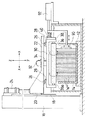
図1は、本発明に係るウェーハ接着剤除去装置の実施の形態の構成を示す正面図であり、図2はその側面図である。
【0008】
図1及び図2に示すように、熱水が貯留された熱水槽10内には、カセット設置台12が設けられている。このカセット設置台12上には、ウェーハWを格納するカセット14が着脱自在に設置されている。四角形状をしたウェーハWは、このカセット14内に、そのスライスベース剥離部(スライスベースが接着されていた部分)の方向を上側にして格納されている(図3参照)。
【0009】
前記熱水槽10の近傍には、支柱16が垂直に立設されている。この支柱16には、一対のガイドレール18、18が配設されており、該ガイドレール18、18には、スライダ20、20を介して昇降テーブル22が昇降自在に支持されている。
前記支柱16の上端部近傍には、前記ガイドレール18、18の配設方向に沿って昇降用油圧シリンダ24が設置されている。この昇降用油圧シリンダ24のロッドは、前記昇降テーブル22に連結されている。前記昇降テーブル22は、この昇降用油圧シリンダ24を駆動することにより、前記ガイドレール18、18に沿って昇降移動する。
【0010】
前記昇降テーブル22の下面には、図中Y方向に沿って一対のガイドレール26、26が配設されている。このガイドレール26、26には、スライダ28、28を介してスライドフレーム30がスライド自在に支持されている。
一方、前記昇降テーブル22の上面には、前記ガイドレール26、26に沿って、スライド用油圧シリンダ32が配設されている。このスライド用油圧シリンダ32のロッドは、連結部材34を介して前記スライドフレーム30に連結されている。前記スライドフレーム30は、このスライド用油圧シリンダ32を駆動することにより、前記ガイドレール26、26に沿って図中Y方向にスライド移動する。
【0011】
前記スライドフレーム30は門型状に形成されており、その下部にはブラシ36が回動自在に支持されている。このブラシ36の軸心36aには、前記スライドフレーム30に設けられたギアボックス38の出力軸が連結されており、該ギアボックス38の入力軸にはモータ40が連結されている。前記ブラシ36は、このモータ40を駆動することにより回転する。
【0012】
なお、ここで使用するブラシ36は、従来よりブラシの素材として用いられている不織布表面処理材を使用する。この不織布表面処理材は、繊維の1本1本に接着剤で研磨砥粒が付着されたナイロン繊維を多数絡み合わせて布状に形成したものであり、前記ブラシ36は、この不織布表面処理材をローラ状に形成したものを用いる。この不織布表面処理材は、弾性力があり非研磨物の形状によく馴染むという特質を有している。
【0013】
前記のごとく構成された本発明に係るウェーハ接着剤除去装置の実施の形態の作用は次の通りである。
まず、所定枚数のウェーハWを、そのスライスベース剥離部の方向を上側にしてカセット14内に格納する。そして、そのウェーハWが格納されたカセット14を熱水槽10内のカセット設置台12上に設置する。
【0014】
なお、この際、昇降テーブル22は、カセット14の設置作業の邪魔にならないように、熱水槽10の上方に設定された待機位置に待機させておく。
以上のように、熱水槽10内にカセット14が設置されると、そのカセット14内に格納されたウェーハWは、熱水中に浸漬されるとともに、そのスライスベース剥離部が図中Y方向に沿って配置される。そして、この後、ウェーハ接着剤除去装置が稼働される。
【0015】
まず、昇降用油圧シリンダ24が駆動され、昇降テーブル22が熱水槽10に向かって下降する。
前記昇降用油圧シリンダ24の駆動は、そのロッドが所定量伸張すると停止され、この結果、前記昇降テーブル22の下部に支持されたブラシ36が、熱水槽10内に設置されたウェーハWの上部、すなわちスライスベース剥離部に当接する。
【0016】
なお、このウェーハWに当接するブラシ36は、前述したように、弾性力を有しているため、適度な押圧力を持ってウェーハWに当接する。
前記昇降用油圧シリンダ24の駆動が停止されると、次いで、ブラシ36に連結されたモータ40が駆動され、この結果、ブラシ36が回転を開始する。
また、前記モータ40の駆動開始とともに、スライドフレーム30に連結されたスライド用油圧シリンダ32が駆動され、この結果、前記ブラシ36が図中Y方向に沿ってスライド移動を開始する。
【0017】
以上の結果、前記ブラシ36は、図3に示すように、回転しながらウェーハWのスライスベース剥離部に沿って摺動する。そして、前記ウェーハWのスライスベース剥離部に残存した接着剤Bは、この回転しながら摺動するブラシ36に擦り取られてウェーハWから除去される。
なお、前記ウェーハWに付着した接着剤Bは、前記ウェーハWが熱水中に浸漬されることにより熱軟化するため、前記のごとく回転しながら摺動するブラシ36が接触すると容易にウェーハWから剥がれ落ちる。したがって、前記ブラシ36を一度通過させることにより、大部分の接着剤Bは除去することができるが、より完全を期するために、ブラシ36は2〜4回程度往復させる。
【0018】
前記ブラシ36の往復操作は、前記スライド用油圧シリンダ32のロッドを伸縮させることにより行うことができ、このブラシ36が所定回往復した後、除去作業を終了する。すなわち、モータ40とスライド用油圧シリンダ32の駆動を停止したのち、昇降用油圧シリンダ24を駆動して昇降テーブル22を待機位置まで上昇させる。そして、熱水槽10からカセット14を取り出す。
【0019】
このように、本実施の形態のウェーハ接着剤除去装置によれば、自動で接着剤の除去を行うことができるとともに、一度に多数のウェーハWを処理することができる。したがって、インゴットから切断された後の一連の処理作業をきわめて効率的に行うことができる。この結果、ウェーハの生産効率が向上する。
なお、本実施の形態の接着剤除去装置では、スライスベースの剥離作業と組み合わせて行うと、より効率的なウェーハの処理が可能になる。すなわち、次の手順に従ってスライスベースの剥離と接着剤の除去を、前述した接着剤除去装置を用いて行う。
【0020】
図4及び図5に示すように、まず、ウェーハWを格納するカセット14を予め熱水槽10内のカセット設置台12上にセットしておく。
次に、ワイヤソー等によって櫛刃状に切断されたウェーハWを、熱水槽10の上方に位置したアーム42で支持し(アーム42については後述)、前記熱水槽10内に浸漬させる。このとき、ウェーハWは、前記熱水槽10内にセットしたカセット14内に収容されるようにして熱水中に浸漬させる。
【0021】
スライスベースに接着されているウェーハWは、熱水中に浸漬させておくことにより、その接着剤が熱軟化して自然にウェーハWから剥離する。剥離したウェーハWは、熱水中を落下してカセット14内に収容される。
このカセット14内に収容されたウェーハWは、全てそのスライスベース剥離部の方向が上側を向くので、全てのウェーハWが自然剥離した後は、上述した手順で接着剤の除去作業を行えばよい。
【0022】
これにより、スライスベースSの剥離と同時に接着剤除去作業を行うことができるので、きわめて効率的である。
なお、前記ウェーハWを支持するアーム42は、図示しない昇降手段により前記熱水槽10に対して昇降自在に設けられており、また、前記昇降テーブル22と接触しないように熱水槽10上から進退自在に設けられている。したがって、スライスベースSの剥離作業が終了したあとは、熱水槽10の上方から退避すれば、接着剤除去作業時に昇降テーブル22等の移動に障害となることはない。
【0023】
また、ウェーハWに接着されスライスベースSは、さらにマウンティングブロックMに接着されているので、前記アーム42でウェーハWを支持するときは、このマウンティングブロックMの両端部を保持する。
次に、本発明に係るウェーハ接着剤除去装置の第2の実施の形態について説明する。
【0024】
図6は、本発明に係るウェーハ接着剤除去装置の第2の実施の形態の構成を示す正面図であり、図7は、その側面図である。
図6及び図7に示すように、熱水が貯留された熱水槽50内には、カセット設置台52が設けられている。このカセット設置台52上には、ウェーハWを格納するカセット54が、縦置きの状態で設置されている。四角形状をしたウェーハWは、このカセット54内に多数積層された状態で格納され、そのスライスベース剥離部の方向をすべて一方向(図7において左方向)に向けられている。
【0025】
前記熱水槽50の近傍には、支柱56が垂直に立設されている。この支柱56には、一対のガイドレール58、58が配設されており、該ガイドレール58、58には、スライダ60、60を介して昇降テーブル62が昇降自在に支持されている。
前記支柱56の上端部近傍には、前記ガイドレール58、58の配設方向に沿って昇降用油圧シリンダ64が設置されている。この昇降用油圧シリンダ64のロッドは、前記昇降テーブル62に連結されている。前記昇降テーブル62は、この昇降用油圧シリンダ64を駆動することにより、前記ガイドレール58、58に沿って昇降移動する。
【0026】
前記昇降テーブル62の下面には、図中Y方向に沿って一対のガイドレール66、66が配設されている。このガイドレール66、66には、スライダ68、68を介して進退スライドフレーム70がスライド自在に支持されている。
一方、前記昇降テーブル62の上面には、前記ガイドレール66、66に沿って、進退スライド用油圧シリンダ72が配設されている。この進退スライド用油圧シリンダ72のロッドは、L字状に形成された連結部材74を介して前記進退スライドフレーム70に連結されている。前記進退スライドフレーム70は、この進退スライド用油圧シリンダ72を駆動することにより、前記ガイドレール66、66に沿って図中Y方向にスライド移動する。
【0027】
前記進退スライドフレーム70は、逆L字状に形成されており、その正面部70Aには、図中X方向に沿ってガイドレール76が配設されている。このガイドレール76には、スライダ78を介してスライドベース80がスライド移動自在に支持されている。
また、前記進退スライドフレーム70の正面70Aには、前記ガイドレール76に沿って、スライド用油圧シリンダ82が配設されている。このスライド用油圧シリンダ82のロッドは、前記スライドベース80に連結されている。前記スライドベース80は、このスライド用油圧シリンダ82を駆動することにより、前記ガイドレール76に沿って図中X方向にスライド移動する。
【0028】
前記スライドベース80には、モータ84が、そのスピンドル84aの方向を鉛直下向きにして設置されている。このモータ84のスピンドル84aには、ブラシ86の軸心86aが連結されており、該ブラシ86は、前記モータ84を駆動することにより回転する。
なお、このブラシ86の構成については、前記第1の実施の形態のブラシ36の構成と同一である。
【0029】
前記のごとく構成された本発明に係るウェーハ接着剤除去装置の第2の実施の形態の作用は次の通りである。
まず、所定枚数のウェーハWを、そのスライスベース剥離部の方向が一定になるように積層してカセット54内に格納する。そして、そのウェーハWが格納されたカセット54を熱水槽50内のカセット設置台52上に設置する。
【0030】
なお、この際、昇降テーブル62は、カセット54の設置作業の邪魔にならないように、熱水槽50の上方に設定された待機位置に待機させておく。
以上のように、熱水槽50内にカセット54が設置されると、そのカセット54内に格納されたウェーハWは、熱水中に浸漬されるとともに、そのスライスベース剥離部が、図中X方向に沿って配置される。そして、この後、ウェーハ接着剤除去装置が稼働される。
【0031】
まず、昇降用油圧シリンダ64が駆動され、昇降テーブル62が熱水槽50に向かって下降する。
前記昇降用油圧シリンダ64の駆動は、そのロッドが所定量伸張すると停止され、この結果、ブラシ86が、前記熱水槽50内に設置されたウェーハWの正面、すなわちスライスベース剥離部の正面に所定の間隔をもって位置する。
【0032】
前記昇降用油圧シリンダ64の駆動が停止されると、次いで、進退スライド用油圧シリンダ72が駆動され、進退スライドフレーム70が図中Y方向(図7において右方向)にスライドする。
前記進退スライド用油圧シリンダ72の駆動は、そのロッドが所定量伸張すると停止され、この結果、前記ブラシ86が前記スライスベース剥離部に当接する。
【0033】
前記進退スライド用油圧シリンダ72の駆動が停止されると、次いで、ブラシ86に連結されたモータ84が駆動され、この結果、ブラシ86が回転を開始する。
また、前記モータ84の駆動開始とともに、スライドベース80に連結されたスライド用油圧シリンダ82が駆動され、この結果、前記ブラシ86が図中X方向に沿ってスライド移動を開始する。
【0034】
以上の結果、前記ブラシ86は、回転しながらウェーハWのスライスベース剥離部に沿って摺動する。そして、前記ウェーハWのスライスベース剥離部に残存した接着剤は、この回転しながら摺動するブラシ86に擦り取られてウェーハWから除去される。
前記ブラシ86が2〜4回程度往復したところで除去作業は終了する。除去作業の終了は、まず、モータ84とスライド用油圧シリンダ82の駆動が停止されついで、進退スライド用油圧シリンダ72が駆動されてブラシ86がウェーハWから退避する。そして、昇降用油圧シリンダ64を駆動されて昇降テーブル62が待機位置まで上昇する。
【0035】
以上一連操作により接着剤除去作業は終了し、除去の終えたウェーハWを熱水槽50からカセット54ごと取り出す。
このように、本実施の形態のウェーハ接着剤除去装置によれば、前記第1の実施の形態と同様に、自動で接着剤の除去を行うことができるとともに、一度に多数のウェーハWを処理することができるため、ウェーハの処理作業を効率的に進めることができる。この結果、ウェーハの生産効率が向上する。
【0036】
なお、本実施の形態では、ブラシ36、86に不織布表面処理材をローラ状に形成したものを用いているが、これに限定されるものではなく、ワイヤブラシや円筒状に形成された研磨砥石等を用いてもよい。
また、本実施の形態では、ウェーハWを熱水中に浸漬させた状態で接着剤の除去作業を行っているが、これは、熱水中に浸漬させることにより、接着剤が熱軟化して除去し易くなるからである。したがって、ブラシ36、86の往復回数を増加させれば、空気中で行っても同様に接着剤の除去を行うことができる。
【0037】
また、本実施の形態では、角形のウェーハWに付着した接着剤を除去する場合について説明したが、本発明は、丸形のウェーハWについても適用することができる。この場合、ブラシ36で接着剤を除去する際にウェーハWが回転するのでこれを防止する必要がある。
前記第1の実施の形態で説明したウェーハWを横置きにするタイプの接着剤除去装置では、図8に示すように、カセット14内に収容されたウェーハW、W、…の一方端をゴム等の弾性体で形成されたパッド90で押圧し、ウェーハW、W、…をカセット14の内壁とで挟持する。これにより、カセット14内に収容されたウェーハW、W、…は固定され回転が防止される。
【0038】
なお、同図に示すように、パッド90の駆動は、パッド90に連結された油圧シリンダ92で行い、該油圧シリンダ92を駆動することにより、前記パッド90はウェーハWの端面に向かって進退移動する。
前記第1の実施の形態で説明したウェーハWを横置きにするタイプの接着剤除去装置では、図8に示すように、カセット14内に収容されたウェーハW、W、…の一方端をゴム等の弾性体で形成されたパッド90で押圧し、ウェーハW、W、…をカセット14の内壁とで挟持する。これにより、カセット14内に収容されたウェーハW、W、…は固定され回転が防止される。
【0039】
なお、同図に示すように、パッド90の駆動は、パッド90に連結された油圧シリンダ92で行い、該油圧シリンダ92を駆動することにより、前記パッド90はウェーハWの端面に向かって進退移動する。
また、前記第2の実施の形態で説明したウェーハWを縦置きにするタイプの接着剤除去装置では、図9に示すように、カセット14内に収容されたウェーハW、W、…の両側部をゴム等の弾性体で形成された一対のパッド94、94で挟持する。これにより、カセット54内に収容されたウェーハW、W、…は固定され回転が防止される。
【0040】
なお、パッド94、94の駆動は、次のように行われる。図9に示すように、前記パッド94、94には、それぞれアーム96、96が連結されており、該アーム96、96は、ガイドレール98、98上をスライド移動自在に支持されたラック部材100、100に連結されている。このラック部材100、100には、ピニオンギア102が噛合されており、該ピニオンギア102には、モータ104が連結されている。前記一対のパッド94、94は、前記モータ104を駆動することにより、互いに近づく方向に移動して、前記ウェーハW、W、…を挟持する。これにより、ウェーハW、W、…の回転が防止される。
【0041】
【発明の効果】
以上説明したように、本発明によれば、自動で接着剤の除去を行うことができるとともに、一度に多数のウェーハWを処理することができるため、きわめて効率的にウェーハの処理作業を進めることができる。この結果、ウェーハの生産効率が向上する。
【図面の簡単な説明】
【図1】本発明に係るウェーハ接着剤除去装置の第1の実施の形態の正面図
【図2】図2の側面図
【図3】本発明に係るウェーハ接着剤除去装置の作用を説明する説明図
【図4】本発明に係るウェーハ接着剤除去装置の他の実施の形態の正面図
【図5】図5の側面図
【図6】本発明に係るウェーハ接着剤除去装置の第2の実施の形態の正面図
【図7】図6の側面図
【図8】本発明に係るウェーハ接着剤除去装置の他の実施の形態の側面図
【図9】本発明に係るウェーハ接着剤除去装置の他の実施の形態の平面図
【符号の説明】
10、50…熱水槽
14、54…カセット
16、56…支柱
22、62…昇降テーブル
24、64…昇降用油圧シリンダ
30…スライドフレーム
32…スライド用油圧シリンダ
36、86…ブラシ
40、84…モータ
70…進退スライドフレーム
72…進退スライド用油圧シリンダ
80…スライドベース
82…スライド用油圧シリンダ
B…接着剤
S…スライスベース
W…ウェーハ[0001]
BACKGROUND OF THE INVENTION
The present invention relates to a wafer adhesive removing device, and more particularly to a wafer adhesive removing device that removes an adhesive remaining on a wafer from which a slice base has been peeled off.
[0002]
[Prior art]
When the ingot is cut, the slice base is bonded to the ingot and cut in order to prevent the end portion from being lost. The slice base is peeled off from the wafer after cutting, and there are various stripping methods such as a hot water method, a heating method, and a dry method.
[0003]
However, in any case, there is a problem that the adhesive used when the slice base is bonded remains on the wafer after peeling.
For this reason, conventionally, after the slice base is peeled from the wafer, the operator removes the adhesive by rubbing the portion of the wafer where the slice base is bonded with a brush.
[0004]
[Problems to be solved by the invention]
However, as described above, the method in which the operator manually removes the adhesive one by one has a problem that the processing takes time and the production efficiency is extremely poor.
The present invention has been made in view of such circumstances, and an object of the present invention is to provide a wafer adhesive removing device capable of automatically removing the adhesive remaining on the wafer after detaching the slice base.
[0005]
[Means for Solving the Problems]
In order to achieve the above object, the present invention provides a wafer adhesive removing apparatus for removing an adhesive remaining in a slice base peeling portion of a wafer from which a slice base has been peeled. The cassette is stored in a fixed direction, the brush is disposed at a position facing the slice base peeling portion of the wafer stored in the cassette, the rotation driving means for rotating the brush, and the brush in the cassette. An advancing / retreating means for moving the brush forward and backward with respect to the slice base peeling portion of the stored wafer; and a moving means for moving the brush along the slice base peeling portion of the wafer stored in the cassette. Contact the slice base peeling portion of the wafer and rotate the brush while rotating the wafer. By sliding along the Isubesu stripping section, and removing the adhesive agent remaining in the slice base peeling portion of the wafer.
[0006]
According to the present invention, the adhesive remaining on the slice base peeling portion of the wafer is removed from the wafer by being scraped by the brush sliding along the slice base peeling portion while rotating.
[0007]
DETAILED DESCRIPTION OF THE INVENTION
Hereinafter, preferred embodiments of a wafer adhesive removing apparatus according to the present invention will be described in detail with reference to the accompanying drawings.
FIG. 1 is a front view showing a configuration of an embodiment of a wafer adhesive removing apparatus according to the present invention, and FIG. 2 is a side view thereof.
[0008]
As shown in FIG.1 and FIG.2, the
[0009]
In the vicinity of the
An elevating
[0010]
A pair of
On the other hand, a slide
[0011]
The
[0012]
In addition, the
[0013]
The operation of the embodiment of the wafer adhesive removing apparatus according to the present invention configured as described above is as follows.
First, a predetermined number of wafers W are stored in the
[0014]
At this time, the lifting table 22 is kept waiting at a standby position set above the
As described above, when the
[0015]
First, the lifting
The driving of the lifting
[0016]
Since the
When the drive of the lifting
As the
[0017]
As a result, the
The adhesive B adhering to the wafer W is thermally softened by immersing the wafer W in hot water. Peel off. Therefore, most of the adhesive B can be removed by passing the
[0018]
The reciprocating operation of the
[0019]
As described above, according to the wafer adhesive removing apparatus of the present embodiment, the adhesive can be automatically removed and a large number of wafers W can be processed at a time. Therefore, a series of processing operations after being cut from the ingot can be performed very efficiently. As a result, wafer production efficiency is improved.
Note that the adhesive removal apparatus of the present embodiment enables more efficient wafer processing when performed in combination with a slice-based peeling operation. That is, the slice base is peeled off and the adhesive is removed using the above-described adhesive removing apparatus according to the following procedure.
[0020]
As shown in FIGS. 4 and 5, first, the
Next, the wafer W cut into a comb blade shape by a wire saw or the like is supported by an
[0021]
By immersing the wafer W bonded to the slice base in hot water, the adhesive softens and peels from the wafer W naturally. The peeled wafer W falls in hot water and is accommodated in the
Since all of the wafers W accommodated in the
[0022]
As a result, the adhesive removing operation can be performed simultaneously with the detachment of the slice base S, which is extremely efficient.
The
[0023]
Further, since the slice base S bonded to the wafer W is further bonded to the mounting block M, both ends of the mounting block M are held when the wafer W is supported by the
Next, a second embodiment of the wafer adhesive removing apparatus according to the present invention will be described.
[0024]
FIG. 6 is a front view showing the configuration of the second embodiment of the wafer adhesive removing apparatus according to the present invention, and FIG. 7 is a side view thereof.
As shown in FIG.6 and FIG.7, the
[0025]
In the vicinity of the
In the vicinity of the upper end of the
[0026]
A pair of
On the other hand, an advancing / retracting
[0027]
The forward /
A slide
[0028]
A
The configuration of the
[0029]
The operation of the second embodiment of the wafer adhesive removing apparatus according to the present invention configured as described above is as follows.
First, a predetermined number of wafers W are stacked and stored in the
[0030]
At this time, the elevating table 62 is kept in a standby position set above the
As described above, when the
[0031]
First, the lifting
The driving of the elevating
[0032]
When the driving of the elevating
The driving of the forward / backward slide
[0033]
When the drive of the forward / backward slide
When the
[0034]
As a result, the
The removal operation ends when the
[0035]
The adhesive removal operation is completed by the above series of operations, and the removed wafer W is taken out from the
As described above, according to the wafer adhesive removing apparatus of the present embodiment, the adhesive can be automatically removed and a large number of wafers W can be processed at a time as in the first embodiment. Therefore, the wafer processing operation can proceed efficiently. As a result, wafer production efficiency is improved.
[0036]
In the present embodiment, the
Moreover, in this Embodiment, although the removal operation | work of the adhesive agent is performed in the state which immersed the wafer W in hot water, this is because an adhesive agent is heat-softened by being immersed in hot water. It is because it becomes easy to remove. Therefore, if the number of reciprocations of the
[0037]
In the present embodiment, the case where the adhesive adhered to the square wafer W is removed has been described. However, the present invention can also be applied to a round wafer W. In this case, since the wafer W rotates when the adhesive is removed by the
In the adhesive removing apparatus of the type in which the wafer W is placed horizontally as described in the first embodiment, as shown in FIG. 8, one end of the wafers W, W,. Are pressed by a
[0038]
As shown in the figure, the
In the adhesive removing apparatus of the type in which the wafer W is placed horizontally as described in the first embodiment, as shown in FIG. 8, one end of the wafers W, W,. Are pressed by a
[0039]
As shown in the figure, the
Further, in the adhesive removing apparatus of the type in which the wafer W described in the second embodiment is placed vertically, as shown in FIG. 9, both side portions of the wafers W, W,. Is sandwiched between a pair of
[0040]
The
[0041]
【The invention's effect】
As described above, according to the present invention, it is possible to automatically remove the adhesive and to process a large number of wafers W at one time. Can do. As a result, wafer production efficiency is improved.
[Brief description of the drawings]
FIG. 1 is a front view of a wafer adhesive removing apparatus according to a first embodiment of the present invention. FIG. 2 is a side view of FIG. 2. FIG. 3 is a diagram for explaining the operation of the wafer adhesive removing apparatus according to the present invention. FIG. 4 is a front view of another embodiment of the wafer adhesive removing apparatus according to the present invention. FIG. 5 is a side view of FIG. 5. FIG. 6 is a second view of the wafer adhesive removing apparatus according to the present invention. FIG. 7 is a side view of FIG. 6. FIG. 8 is a side view of another embodiment of the wafer adhesive removing apparatus according to the present invention. FIG. 9 is a wafer adhesive removing apparatus according to the present invention. Plan view of other embodiments [Explanation of symbols]
DESCRIPTION OF
Claims (2)
複数枚のウェーハを、そのスライスベース剥離部の方向を一定にして格納するカセットと、
前記カセットに格納されたウェーハのスライスベース剥離部と対向する位置に配置されたブラシと、
前記ブラシを回転させる回転駆動手段と、
前記ブラシを前記カセットに格納されたウェーハのスライスベース剥離部に対して進退移動させる進退移動手段と、
前記ブラシを前記カセットに格納されたウェーハのスライスベース剥離部に沿って移動させる移動手段と、
からなり、前記ブラシを前記ウェーハのスライスベース剥離部に当接し、該ブラシを回転させながら前記ウェーハのスライスベース剥離部に沿って摺動させることにより、前記ウェーハのスライスベース剥離部に残存する接着剤を除去することを特徴とするウェーハ接着剤除去装置。In the wafer adhesive removing device for removing the adhesive remaining in the slice base peeling portion of the wafer from which the slice base has been peeled,
A cassette for storing a plurality of wafers with the direction of the slice base peeling portion being constant,
A brush disposed at a position facing the slice base peeling portion of the wafer stored in the cassette;
Rotation driving means for rotating the brush;
Forward / backward moving means for moving the brush forward / backward with respect to the slice base peeling portion of the wafer stored in the cassette;
Moving means for moving the brush along the slice base peeling portion of the wafer stored in the cassette;
The brush is brought into contact with the slice base peeling portion of the wafer, and the brush remains on the slice base peeling portion of the wafer by sliding along the slice base peeling portion of the wafer while rotating the brush. A wafer adhesive removing apparatus, wherein the agent is removed.
Priority Applications (1)
| Application Number | Priority Date | Filing Date | Title |
|---|---|---|---|
| JP08681397A JP3716541B2 (en) | 1997-04-04 | 1997-04-04 | Wafer adhesive remover |
Applications Claiming Priority (1)
| Application Number | Priority Date | Filing Date | Title |
|---|---|---|---|
| JP08681397A JP3716541B2 (en) | 1997-04-04 | 1997-04-04 | Wafer adhesive remover |
Publications (2)
| Publication Number | Publication Date |
|---|---|
| JPH10284447A JPH10284447A (en) | 1998-10-23 |
| JP3716541B2 true JP3716541B2 (en) | 2005-11-16 |
Family
ID=13897260
Family Applications (1)
| Application Number | Title | Priority Date | Filing Date |
|---|---|---|---|
| JP08681397A Expired - Fee Related JP3716541B2 (en) | 1997-04-04 | 1997-04-04 | Wafer adhesive remover |
Country Status (1)
| Country | Link |
|---|---|
| JP (1) | JP3716541B2 (en) |
Families Citing this family (4)
| Publication number | Priority date | Publication date | Assignee | Title |
|---|---|---|---|---|
| JP6297924B2 (en) * | 2014-05-29 | 2018-03-20 | リンテック株式会社 | Adhesive layer removing apparatus and adhesive layer removing method |
| KR102507049B1 (en) * | 2022-10-28 | 2023-03-07 | 손귀욱 | Single wafer separator for semiconductor wafers |
| KR102507055B1 (en) * | 2022-10-28 | 2023-03-07 | 손귀욱 | Single wafer separator for semiconductor wafers |
| KR102519871B1 (en) * | 2022-10-28 | 2023-04-11 | 손귀욱 | Single Wafer Separation System |
-
1997
- 1997-04-04 JP JP08681397A patent/JP3716541B2/en not_active Expired - Fee Related
Also Published As
| Publication number | Publication date |
|---|---|
| JPH10284447A (en) | 1998-10-23 |
Similar Documents
| Publication | Publication Date | Title |
|---|---|---|
| JP4617028B2 (en) | Processing strain remover | |
| CN108326560B (en) | Burr cleaning device for electric appliance aluminum frame | |
| JP2011062759A (en) | Grinding method and grinding device for abrasive cloth of double-sided polishing apparatus | |
| JP3716541B2 (en) | Wafer adhesive remover | |
| JP2982125B2 (en) | Polishing method for disk-shaped workpiece and apparatus for performing the polishing method | |
| CN216066930U (en) | Burnishing machine is used in stone material processing that simple operation and work efficiency are high | |
| CN112676948B (en) | Intelligent manufacturing steel rapid polishing equipment | |
| JP3910351B2 (en) | Fixed abrasive wire tool cleaning device | |
| JPH06208979A (en) | Manufacturing system for semiconductor wafer | |
| JP4295469B2 (en) | Polishing method | |
| JP2917262B2 (en) | Semiconductor wafer cleaning / drying equipment | |
| CN216759265U (en) | Metal pipeline port burr grinding device | |
| CN216657526U (en) | Mould processing surface finish device convenient to remove | |
| CN211219953U (en) | Steel plate pretreatment equipment | |
| JP2004291200A (en) | Groove working device | |
| JPH0790453B2 (en) | Plate-shaped body grinding method and apparatus | |
| CN220260409U (en) | Grinding device | |
| JP3119324B2 (en) | Wafer slice-based stripper | |
| JPH059229B2 (en) | ||
| CN214445191U (en) | Data processing burr device for preventing chips from flying out | |
| CN219189779U (en) | Polishing machine for hardware processing | |
| CN213197002U (en) | Stainless steel knife and fork polishing device | |
| CN211413872U (en) | Cutting device for gear machining | |
| JP3003079U (en) | Rubber burr removal equipment | |
| CN117019807A (en) | Dish washing equipment |
Legal Events
| Date | Code | Title | Description |
|---|---|---|---|
| A977 | Report on retrieval |
Free format text: JAPANESE INTERMEDIATE CODE: A971007 Effective date: 20050804 |
|
| TRDD | Decision of grant or rejection written | ||
| A01 | Written decision to grant a patent or to grant a registration (utility model) |
Free format text: JAPANESE INTERMEDIATE CODE: A01 Effective date: 20050809 |
|
| A61 | First payment of annual fees (during grant procedure) |
Free format text: JAPANESE INTERMEDIATE CODE: A61 Effective date: 20050822 |
|
| R150 | Certificate of patent or registration of utility model |
Free format text: JAPANESE INTERMEDIATE CODE: R150 |
|
| FPAY | Renewal fee payment (event date is renewal date of database) |
Free format text: PAYMENT UNTIL: 20080909 Year of fee payment: 3 |
|
| FPAY | Renewal fee payment (event date is renewal date of database) |
Free format text: PAYMENT UNTIL: 20090909 Year of fee payment: 4 |
|
| FPAY | Renewal fee payment (event date is renewal date of database) |
Free format text: PAYMENT UNTIL: 20090909 Year of fee payment: 4 |
|
| FPAY | Renewal fee payment (event date is renewal date of database) |
Free format text: PAYMENT UNTIL: 20100909 Year of fee payment: 5 |
|
| FPAY | Renewal fee payment (event date is renewal date of database) |
Free format text: PAYMENT UNTIL: 20100909 Year of fee payment: 5 |
|
| FPAY | Renewal fee payment (event date is renewal date of database) |
Free format text: PAYMENT UNTIL: 20110909 Year of fee payment: 6 |
|
| FPAY | Renewal fee payment (event date is renewal date of database) |
Free format text: PAYMENT UNTIL: 20120909 Year of fee payment: 7 |
|
| FPAY | Renewal fee payment (event date is renewal date of database) |
Free format text: PAYMENT UNTIL: 20130909 Year of fee payment: 8 |
|
| R250 | Receipt of annual fees |
Free format text: JAPANESE INTERMEDIATE CODE: R250 |
|
| R250 | Receipt of annual fees |
Free format text: JAPANESE INTERMEDIATE CODE: R250 |
|
| LAPS | Cancellation because of no payment of annual fees |