JP3716347B2 - Induction motor drive device, induction motor control device, and induction motor control method - Google Patents
Induction motor drive device, induction motor control device, and induction motor control method Download PDFInfo
- Publication number
- JP3716347B2 JP3716347B2 JP2002148829A JP2002148829A JP3716347B2 JP 3716347 B2 JP3716347 B2 JP 3716347B2 JP 2002148829 A JP2002148829 A JP 2002148829A JP 2002148829 A JP2002148829 A JP 2002148829A JP 3716347 B2 JP3716347 B2 JP 3716347B2
- Authority
- JP
- Japan
- Prior art keywords
- frequency
- command value
- induction motor
- current
- value
- Prior art date
- Legal status (The legal status is an assumption and is not a legal conclusion. Google has not performed a legal analysis and makes no representation as to the accuracy of the status listed.)
- Expired - Lifetime
Links
Images


Description
【0001】
【発明の属する技術分野】
本発明は,誘導電動機をベクトル制御により可変速制御する駆動装置に係り、具体的には起動ないし加速時における制御技術に属する。
【0002】
【従来の技術】
誘導電動機をベクトル制御により可変速制御する場合、速度指令値ωr*にすべり周波数ωsを加算してインバータの周波数指令値ω1*を求め、これに基づいてd軸電圧指令値Vd*、q軸電圧指令値Vq*及び位相θを演算して、誘導電動機に供給する交流電圧をベクトル制御して速度を可変している。つまり、周波数指令値ω1*に対応した位相θによりVd*、Vq*を座標変換して、周波数指令値に対応した周波数を有する交流電圧指令値Vu*、Vv*、Vw*を生成し、これに基づいてインバータを可変速制御している。なお、通常のベクトル制御では電動機の磁束に平行な成分をd軸、垂直な成分をq軸と定義している。
【0003】
ここで、d軸電圧指令値Vd*とq軸電圧指令値Vq*の理論式を数1と数2に示す。それらの式において、r1は誘導電動機の一次抵抗、Mは相互インダクタンス、L2は二次側自己インダクタンス、Lσは漏れインダクタンス一次側換算値の和を示す。
【0004】
【数1】

【数2】
【0006】
【数3】
【0007】
【数4】
【0008】
【数5】
【数6】
【0010】
【発明が解決しようとする課題】
しかし、従来方式においては、誘導電動機の起動や加速時のように、電動機の発生トルクに対して負荷トルクが大きい場合には、過渡的に数5、数6の条件が崩れて磁束が変動し、トルクτが不足して起動失敗や加速失敗に至る場合がある。これは、起動時のように負荷トルクが大きいと、実際のすべり周波数ωsが急激に増加し、電流Id、Iqがその変化に追従できない場合が生ずることによる。
【0011】
すなわち、前述したように、ベクトル制御はΦ2q=0、Φ2d>0の条件が満たされているものとして制御理論が組み立てられている。しかし、数6のΦ2qの理論式には、実すべり周波数ωs(=ω1*−実モータ速度)が負の項に含まれているため、起動時又は加速時に周波数指令値ω1*を急激に増加させることにより実すべり周波数ωsが増加すると、過渡的にΦ2qが定常時の“0”から負側(Φ2q<0)になる。Φ2qが負になると、数5から明らかなように、Φ2dが減少する。その結果、トルクτ=Φ2d×Iqが減少し、発生トルクがますます不足して起動及び加速できないという問題が出るのである。
【0012】
そこで、本発明は、誘導電動機の起動時や加速時における過渡的な磁束低下を抑制し、十分なトルクを発生させることを課題とする。
【0013】
【課題を解決するための手段】
本発明は、次に述べる手段により、上記課題を解決するものである。
【0014】
本発明は、速度指令値にすべり周波数に相関する物理量の修正値を加算し、該修正された速度指令値に基づいて出力電圧の周波数を制御して誘導電動機をベクトル制御する誘導電動機駆動装置において、前記すべり周波数に相関する物理量に応じて前記修正値を低減補正することを特徴とする。
【0015】
すなわち、負荷トルクが大きい場合に周波数指令を増加させると、実すべり周波数が増大するから、すべり周波数に相関する物理量の修正値が増大し、これにより益々周波数指令値が高くなる一方、電流Id、Iqの制御がその変化に追従できないために、ますます発生トルクが不足することになる。
【0016】
そこで、本発明は、少なくとも出力電圧の周波数制御に係る速度指令値に加算する修正値を、例えば、すべり周波数推定値よりも小さな値に低減補正することにより、周波数制御に係る速度指令値を実際の電動機速度に近付けて実すべり周波数を低減するようにしたのである。その結果、電流Id、Iq制御の追従性が改善され、十分なトルクを発生させることができるのである。
【0017】
ここで、修正値を補正する因子のすべり周波数に相関する物理量は、電動機電流と電動機の発生トルクと電動機電流に基づいて推定されるすべり周波数推定値の少なくとも1つを適用できる。この場合、すべり周波数に相関する物理量が設定値以上のときと、変化率の少なくとも一方に応じて修正値を低減補正することが好ましい。また、速度指令値が設定値以下のときに、修正値を低減補正するようにしてもよい。この場合、修正値の低減補正の度合いは、速度指令値が設定値以下のときに、速度指令値に応じて変えるようにすることができる。
【0018】
ところで、上記のように低減補正すると、修正値は、同一トルク条件もしくは同一電動機電流条件下で、所定の電動機速度以下における値が該所定の電動機速度以上における値よりも小さくなる。
【0019】
【発明の実施の形態】
以下、本発明の実施の形態について図を用いて説明する。
(第一実施形態)
本発明の第一の実施形態について、図1〜図3を用いて説明する。図2は、本発明に係る誘導電動機駆動装置の第一実施形態及び周辺部を含む全体構成図である。図1は、図2の交流電圧指令演算部20の詳細構成図である。
【0020】
図2に示すように、誘導電動機駆動装置は、交流電源1から供給される三相交流電圧を順変換器2で直流電圧に変換し、変換された直流電圧を平滑コンデンサ3で平滑し、平滑された直流電圧を逆変換器4により所望の周波数の三相交流電圧に変換して誘導電動機6に供給するようになっている。逆変換器4は、例えばIGBTなどの半導体スイッチ素子を用いて構成され、それらの半導体スイッチ素子はPWMゲートパルス演算部11で生成されたゲート信号によって制御される。PWMゲートパルス演算部11へ入力される交流電圧指令値は、電流検出部5により検出された電動機電流と速度指令値ωr*に基づいて交流電圧指令演算部20で演算により求められるようになっている。
【0021】
次に、交流電圧指令演算部20の詳細について述べる。第一実施形態は、誘導電動機の起動時や加速時等のように負荷トルクが大きい時に周は巣指令を増加させた場合に起きる過渡的なトルク不足を補償するため、位相θ及びd軸電圧指令値Vd*の演算に用いる周波数指令値ω1*を、すべり周波数推定値ωs’に相関させた小さな値より修正することを特徴とする。つまり、周波数指令値自体を低減すると共に、数5、数6で説明したように、実すべり周波数ωsが大きくなるとΦ2dが減少するので、その減少を抑えるためである。
【0022】
一方、q軸電圧指令値Vq*の演算に用いるすべり周波数推定値ωs’は、従来同様に、例えば数3により求めた値とすることを特徴とする。その理由は、Vq*=ω1*×Φ2qであるから、すべり周波数推定値ωs’を小さく補正すると、ω1*が小さくなってVq*が低下し、Iqが下がって、却ってトルクが減少してしまうからである。
【0023】
図1において、図示していない制御器等から入力される速度指令値ωr*は、加算器21、22に入力されている。すべり周波数演算部23は、電動機電流Imをdq軸座標変換して得られるIdFBとIqFBを入力し、数3に基づいてすべり周波数推定値ωs’を演算して出力するように構成されている。なお、IdFB、IqFBは検出値に代えて制御部内で生成される電流指令値Id*、Iq*を用いることも、よく知られている。また、IdFB、IqFBは図示していない座標変換部により、電動機電流Imをdq軸座標系に変換して得られることもよく知られている。
【0024】
すべり周波数補正部24は、すべり周波数演算部23から出力されるすべり周波数推定値ωs’を入力し、これに係数k(ただし、0≦k<1)を掛けてすべり周波数補正値k・ωs’を出力する。つまり、加算器21に入力されるすべり周波数補正値k・ωs’は、加算器22に入力されるすべり周波数推定値ωs’に比例し、かつすべり周波数推定値ωs’よりも小さい値である。また、すべり周波数推定値ωs’とすべり周波数補正値k・ωs’は、図3に示すすべり周波数演算部23とすべり周波数補正部24において、電動機電流に基づいてそれぞれ独立に求めるようにしてもよい。
【0025】
加算器21と加算器22は、速度指令値ωr*にすべり周波数を加算して修正する部分である。加算器21は、出力(ωr*+k・ωs’)を周波数指令値ω1*Cとして位相演算部25に、また周波数指令値ω1*BとしてVd*演算部26に入力する。また、加算器22は、出力(ωr*+ωs’)を周波数指令値ω1*AとしてVq*演算部27に入力する。Vd*演算部26は、入力される励磁電流指令値Id*とトルク電流指令値Iq*及び周波数指令値ω1*Bを用いて、d軸電圧指令値Vd*を演算する。Vq*演算部27は、励磁電流指令値Id*とトルク電流指令Iq*及び周波数指令値ω1*A を用いて、q軸電圧指令値Vq*を演算する。位相演算部25においては、周波数指令値ω1*C を積分して位相θを演算する。座標変換部28は、d軸電圧指令値Vd*とq軸電圧指令値Vq*を位相θに従って座標変換を行い、周波数指令値ω1*Cに対応する周波数の交流電圧指令値Vu*、Vv*、Vw*を生成し、図1のPWMゲートパルス演算部11に出力する。
【0026】
次に、本実施形態の動作を説明する。ここで、位相θを演算する際の周波数指令値ω1*Cと、Vd*の演算に用いる周波数指令値ω1*Bは、何れも加算器21の出力(ωr*+k・ωs’)であるから本来同一値であるが、理論式の理解を助けるために、便宜的に両者を区別して表している。本実施形態のVd*、Vq*は、数7〜数9の様になり、電動機電流Id、Iqは数10〜12の様になる。なお、rσは電動機抵抗の一次側換算値の和である。
【0027】
【数7】
![]()
【数8】
【数9】
【数10】
【数11】
【数12】
【0033】
【数13】
【0034】
ところで、Vd*演算用の周波数指令値ω1*Bを、位相θ演算用の周波数指令値ω1*Cと同一にしたのは、仮に、ω1*B>ω1*Cにすると、数7のVd*を数10に代入して明らかなように、Idが低下して磁束及びトルクが減少するからである。そこで、本実施形態では、ω1*B=ω1*Cに設定することにより、Idの低下を抑えて磁束Φ2dの低減を抑制しているのである。
【0035】
このように、本実施形態は、インバータを制御する周波数指令値ω1*Cを小さな値に補正し、周波数指令値ω1*Cを電動機の実回転速度に近付けて、実すべり周波数の急激な増加に起因する過渡的な磁束低下を抑制して、十分なトルクを発生させることを本旨とする。
【0036】
また、周波数指令値ω1*Cに合わせてd軸電圧指令値Vd*を制御する周波数指令値ω1*Bを小さな値に補正することが好ましい。これによれば、(ω1*C−ω1*B)の要素を含むd軸励磁電流Idの低下を抑えてトルクの低下を抑えることができる。
【0037】
更に、q軸電圧指令値Vq*の制御に用いる周波数指令値ω1*Aは、周波数指令値ω1*Cよりも大きな値にすることが好ましい。例えば、すべり周波数推定値を基準にして制御することにより、q軸電流Iqの低下を抑えてトルクの低下を抑えることができる。
【0038】
ここで、図4を用いて、本実施形態による検証結果を説明する。図4は、本実施形態を用いた場合と従来方式の場合の電動機起動特性のシミュレーション結果を示す。従来方式においては、周波数指令を増加させた場合、磁束が低下してトルク電流が許容値以上に流れているにも拘わらず、トルクは起動トルクにも達していない。これに対し、本発明方式においては、周波数指令増加後に磁束は一旦下がるものの、直ぐに増加し、トルク電流が許容値以下で起動トルクが発生している。このため、従来方式では起動失敗を起こし電動機速度はゼロのままだが、本発明方式によれば電動機の起動が達成されている。
(第二実施形態)
本発明の第二実施形態を図5〜図7を用いて説明する。本実施形態が図1の実施形態と異なる部分は、すべり周波数補正部24に代えて、数9における係数kを速度指令値ωr*に応じて変化させるようにしたすべり周波数補正部30を設けたことにある。その他については、第一実施形態と同一であることから、同一符号を付して説明を省略する。
【0039】
つまり、図1の実施形態において、係数kを一定値に保持すると、電動機が起動又は加速して所定の速度に到達した場合でも、周波数指令値ω1*Aと周波数指令値ω1*Bが異なったままになり、定常状態において磁束の不安定要因となる。
【0040】
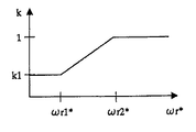
そこで、本実施形態のすべり周波数補正部30は、速度指令ωr*を取り込み、ωr*に応じて係数kを増加し、所定以上の速度において係数kを“1”に変更して、周波数指令値ω1*Aと周波数指令値ω1*Bを一致させるようにしている。すなわち、すべり周波数補正部30は、例えば図6に示すように、速度指令ωr*が停止時からωr1*までは数9の係数kをk1(0≦k1<1)に設定し、ωr1*からωr2*までは徐々に増加させて、ωr2*以上でk=1に変更するように設定する。例えば、ωr1*は定格速度の3~4%、ωr2*は定格速度の10%程度に設定することができる。
【0041】
なお、速度指令ωr*に応じて係数kを増加する方法は、図6に限らず図7のようにすることができる。つまり、ωr*がωr1*に到達した時間t1から所定の時間t2までの間はkをk1から1に徐々に変化させる。図6、図7のように、係数kを一定の増加率で緩やかに“1”に変化させる理由は、kを例えばステップ的に“1”に増加すると、過渡的なトルク変動を生じるからである。そこで、kを“1”に変化させる時間は、例えば電流が変化する場合の時定数Tσ(=Lσ/rσ)の1/10以上から、磁束が変化する場合の時定数T2の10倍程度とするのが好ましい。(第三実施形態)
本発明の第三の実施形態を図8に示す。本実施形態が図5の実施形態と異なる点は、すべり周波数補正部30の係数kを電動機電流に応じて変化させるようにした点にある。例えば、トルク電流Iqが所定値を超える場合、それは磁束が十分でないことが原因と考えられる。そこで、トルク電流Iqが所定値Iqrefを越えた場合、すべり周波数補正値k・ωs’を更に小さくする。これにより、第一実施例で述べたように磁束Φ2dの低下を抑制して、Iqの増加を抑えることができる。ここで、Iqrefの設定値は、インバータに流すことができる許容電流値よりも低く設定する。この本実施形態によれば、電動機の起動又は加速時における過電流を抑制する効果もある。
【0042】
上述した第二及び第三実施形態は、見方を変えると、すべり周波数推定値ωs’は、同一トルクもしくは同一電流の条件下では電動機速度に関わらず同一である。一方、すべり周波数補正値k・ωs’は、同一トルクもしくは同一電流の条件下では、低速度領域と高速度領域で値が異なるように設定される。そして、電動機の起動又は加速時における磁束の低下を抑制して高トルクを得ることができる。特に、第二及び第三実施形態によれば、加速後の高速運転時においても安定した運転を行うことができる。
【0043】
また、図5、図8の実施形態では、すべり周波数補正部24の係数kを速度指令値又は電動機電流に応じて変化させるようにしたが、これに代えてすべり周波数補正部24はすべり周波数推定値ωs’の急激な変化を抑えるように、例えばωs’の変化率を制限する要素を用いることができる。
(第四実施形態)
図9に、本発明の第四実施形態の交流電圧指令演算部の構成図を示す。本実施形態は第一実施形態に対して演算の手順が異なるだけであり、実質的に等価である。すなわち、Vq*演算部27に入力する周波数指令を、Vd*演算部26に入力する周波数指令ω1*Bと同じにする。そして、すべり周波数推定値ωs’からすべり周波数補正値k・ωs’を減算する減算器31を設け、この減算器31の出力(1−k)ωs’をVq*補正値演算部32に入力する。Vq*補正値演算部32は、数14によりΔVq*を求めて加算器33に出力してVq*演算部27の出力の電圧指令値Vq*に加算してVq*補正するようにしている。
【0044】
つまり、Vd*演算部26とVq*演算部27は、各々数1、2に従って演算する。Vq*補正値演算部32は、数14にしたがってΔVq*を演算する。
【0045】
【数14】
また、図9のすべり周波数補正部24に代えて、図5又は図8のすべり周波数補正部30を適用し、電動機速度が所定の速度に達した際に、係数kをωr*もしくは電動機電流に基づいて変化させることにより、第二又は第三実施形態と同様の効果が得られる。
【0046】
ここで、第四実施形態及びその変形例について、見方を変えると、同一トルクもしくは同一電流の条件下において、低速度領域におけるVq*補正値ΔVq*を高速度領域での値より大きく設定して、電動機の起動又は加速時における磁束低下を抑制して高トルクを得ているということができる。また、第四実施形態の変形例によれば、加速後の高速運転時でも安定した運転を行うことができる。
(第五実施形態)
図10に第五実施形態の特徴部の構成を示す。本実施形態のすべり周波数演算部34は、トルク電流の検出値IqFBと、励磁電流の指令値Id*とから、数15に基づいて、すべり周波数推定値ωs’を演算する。数15は数4のIdFBを指令値Id*に置き換えたものである。定常状態においてはIdFB=Id*となるから、数15は数4と等価となる。
【0047】
【数15】
【0048】
【数16】
【0049】
なお、本実施形態では図示を省略したが、Vq*演算部27及び位相演算部25は、加算器21から出力される周波数指令値ω1*に基づいて、それぞれVq*及びθを演算する。
【0050】
なお、kを変化させる場合は、急峻なトルクの変動を防止するため、例えば、電流が変化する場合の時定数Tσ(=Lσ/rσ)の1/10以上から、磁束が変化する場合の時定数T2の10倍の時間でkを0から1に変化させるようなレートで行なえばよい。
【0051】
【発明の効果】
以上述べたように、本発明によれば、誘導電動機の起動時や加速時にも十分なトルクを発生させることができる。
【0052】
また、d軸電圧指令値の演算及び位相の演算に用いる周波数指令値を、電動機電流に応じて小さく修正するようにしたものによれば、起動時や加速時にも十分なトルクを発生させ、かつ過電流を抑制する効果がある。
【0053】
また、d軸電圧指令値の演算及び位相の演算に用いる周波数指令値を、速度指令値又は電動機電流に応じて補正して小さい値にしたものによれば、加速後の高速運転時においても安定して運転を行える効果がある。
【図面の簡単な説明】
【図1】本発明の誘導電動機駆動装置の特徴部に係る一実施の形態の交流電圧指令演算部の構成図である。
【図2】本発明の誘導電動機駆動装置に係る一実施の形態の全体構成図である。
【図3】図1のすべり周波数補正部の変形例を示す図である。
【図4】図1実施形態の効果を説明する動作波形図である。
【図5】本発明の誘導電動機駆動装置の特徴部に係る他の実施の形態の交流電圧指令演算部の構成図である。
【図6】図5実施形態のすべり周波数補正部の係数kの設定法を説明する図である。
【図7】図5実施形態のすべり周波数補正部の係数kの他の設定法を説明する図である。
【図8】本発明の誘導電動機駆動装置の特徴部に係る更に他の実施の形態の交流電圧指令演算部の構成図である。
【図9】本発明の誘導電動機駆動装置の特徴部に係る更に他の実施の形態の交流電圧指令演算部の構成図である。
【図10】本発明の誘導電動機駆動装置の特徴部に係る更に他の実施の形態の交流電圧指令演算部に係る主要部の構成図である。
【符号の説明】
20 交流電圧指令演算手段
21、22 加算器
23 すべり周波数演算部
24 すべり周波数補正部
25 位相演算部
26 Vd*演算部
27 Vq*演算部
28 座標変換部[0001]
BACKGROUND OF THE INVENTION
The present invention relates to a drive device that performs variable speed control of an induction motor by vector control, and specifically relates to a control technique during start-up or acceleration.
[0002]
[Prior art]
When the induction motor is controlled at a variable speed by vector control, the slip frequency ωs is added to the speed command value ωr * to obtain the inverter frequency command value ω1 *, and based on this, the d-axis voltage command value Vd * and the q-axis voltage are obtained. The command value Vq * and the phase θ are calculated, and the AC voltage supplied to the induction motor is vector-controlled to vary the speed. That is, Vd * and Vq * are coordinate-transformed by the phase θ corresponding to the frequency command value ω1 * to generate AC voltage command values Vu *, Vv * and Vw * having frequencies corresponding to the frequency command value. Based on the above, the inverter is controlled at a variable speed. In normal vector control, the component parallel to the magnetic flux of the motor is defined as the d-axis, and the component perpendicular to the q-axis is defined as the q-axis.
[0003]
Here, the theoretical expressions of the d-axis voltage command value Vd * and the q-axis voltage command value Vq * are shown in
[0004]
[Expression 1]
[Expression 2]
[0006]
[Equation 3]
[0007]
[Expression 4]
[0008]
[Equation 5]
[Formula 6]
[0010]
[Problems to be solved by the invention]
However, in the conventional method, when the load torque is larger than the generated torque of the motor, such as when the induction motor is started or accelerated, the conditions of Equations 5 and 6 are transiently broken and the magnetic flux fluctuates. In some cases, the torque τ is insufficient, leading to a start failure or acceleration failure. This is because when the load torque is large as at the time of start-up, the actual slip frequency ωs increases rapidly and the currents Id and Iq may not be able to follow the change.
[0011]
That is, as described above, the control theory is assembled assuming that the vector control satisfies the conditions of Φ2q = 0 and Φ2d> 0. However, since the actual slip frequency ωs (= ω1 * -actual motor speed) is included in the negative term in the theoretical formula of Φ2q in Equation 6, the frequency command value ω1 * increases rapidly during startup or acceleration. When the actual slip frequency ωs increases, Φ2q transiently changes from “0” in the steady state to the negative side (Φ2q <0). When Φ2q becomes negative, Φ2d decreases as is clear from Equation 5. As a result, the torque τ = Φ2d × Iq decreases, and the problem arises that the generated torque becomes more and more insufficient and cannot be started up and accelerated.
[0012]
Therefore, an object of the present invention is to suppress a transient decrease in magnetic flux at the time of starting or accelerating the induction motor and generate a sufficient torque.
[0013]
[Means for Solving the Problems]
The present invention solves the above problems by the following means.
[0014]
The present invention relates to an induction motor driving device that adds a correction value of a physical quantity correlated with a slip frequency to a speed command value, and controls the frequency of an output voltage based on the corrected speed command value to perform vector control of the induction motor. The correction value is reduced and corrected in accordance with a physical quantity correlated with the slip frequency.
[0015]
That is, when the frequency command is increased when the load torque is large, the actual slip frequency increases, so that the correction value of the physical quantity correlated with the slip frequency increases, thereby increasing the frequency command value while the current Id, Since the control of Iq cannot follow the change, the generated torque becomes increasingly insufficient.
[0016]
Therefore, the present invention actually reduces the speed command value related to frequency control by reducing and correcting a correction value added to at least the speed command value related to frequency control of the output voltage, for example, to a value smaller than the estimated slip frequency value. The actual slip frequency was reduced by approaching the motor speed. As a result, the followability of the current Id and Iq control is improved, and sufficient torque can be generated.
[0017]
Here, at least one of the estimated slip frequency values estimated based on the motor current, the generated torque of the motor, and the motor current can be applied to the physical quantity correlated with the slip frequency as a factor for correcting the correction value. In this case, it is preferable to reduce and correct the correction value in accordance with at least one of the change rate and the physical quantity correlated with the slip frequency. Further, when the speed command value is equal to or less than the set value, the correction value may be corrected to be reduced. In this case, the degree of correction correction of the correction value can be changed according to the speed command value when the speed command value is equal to or less than the set value.
[0018]
By the way, when the reduction correction is performed as described above, the correction value becomes smaller than a value above the predetermined motor speed when the value is lower than the predetermined motor speed under the same torque condition or the same motor current condition.
[0019]
DETAILED DESCRIPTION OF THE INVENTION
Hereinafter, embodiments of the present invention will be described with reference to the drawings.
(First embodiment)
A first embodiment of the present invention will be described with reference to FIGS. FIG. 2 is an overall configuration diagram including the first embodiment of the induction motor driving device according to the present invention and peripheral portions. FIG. 1 is a detailed configuration diagram of the AC voltage
[0020]
As shown in FIG. 2, the induction motor driving device converts the three-phase AC voltage supplied from the
[0021]
Next, details of the AC voltage
[0022]
On the other hand, the slip frequency estimated value ωs ′ used for the calculation of the q-axis voltage command value Vq * is a value obtained by, for example,
[0023]
In FIG. 1, a speed command value ωr * input from a controller or the like (not shown) is input to
[0024]
The slip
[0025]
The
[0026]
Next, the operation of this embodiment will be described. Here, the frequency command value ω1 * C for calculating the phase θ and the frequency command value ω1 * B used for calculating Vd * are both outputs (ωr * + k · ωs ′) of the
[0027]
[Expression 7]
![]()
[Equation 8]
[Equation 9]
[Expression 10]
[Expression 11]
[Expression 12]
[0033]
[Formula 13]
[0034]
By the way, the frequency command value ω1 * B for Vd * calculation is made the same as the frequency command value ω1 * C for phase θ calculation. If ω1 * B> ω1 * C, then Vd * This is because Id is lowered and magnetic flux and torque are reduced as is apparent by substituting. Therefore, in this embodiment, by setting ω1 * B = ω1 * C, the decrease in Id is suppressed and the decrease in magnetic flux Φ2d is suppressed.
[0035]
As described above, in this embodiment, the frequency command value ω1 * C for controlling the inverter is corrected to a small value, and the frequency command value ω1 * C is brought close to the actual rotational speed of the motor, so that the actual slip frequency is increased rapidly. The main purpose is to generate a sufficient torque while suppressing the transitional magnetic flux drop caused by the phenomenon.
[0036]
Further, it is preferable to correct the frequency command value ω1 * B for controlling the d-axis voltage command value Vd * to a small value in accordance with the frequency command value ω1 * C. According to this, it is possible to suppress a decrease in torque by suppressing a decrease in d-axis excitation current Id including the element (ω1 * C−ω1 * B).
[0037]
Furthermore, it is preferable that the frequency command value ω1 * A used for controlling the q-axis voltage command value Vq * is larger than the frequency command value ω1 * C. For example, by controlling on the basis of the estimated slip frequency value, it is possible to suppress a decrease in torque by suppressing a decrease in the q-axis current Iq.
[0038]
Here, the verification result according to the present embodiment will be described with reference to FIG. FIG. 4 shows the simulation results of the motor starting characteristics when this embodiment is used and when the conventional method is used. In the conventional method, when the frequency command is increased, the torque does not reach the starting torque even though the magnetic flux decreases and the torque current flows above the allowable value. On the other hand, in the method of the present invention, the magnetic flux once decreases after the frequency command increases, but increases immediately, and the starting torque is generated when the torque current is below the allowable value. For this reason, in the conventional method, starting failure occurs and the motor speed remains zero, but the starting of the motor is achieved according to the method of the present invention.
(Second embodiment)
A second embodiment of the present invention will be described with reference to FIGS. The present embodiment differs from the embodiment of FIG. 1 in that a slip
[0039]
That is, in the embodiment of FIG. 1, when the coefficient k is held at a constant value, the frequency command value ω1 * A and the frequency command value ω1 * B differ even when the motor starts or accelerates and reaches a predetermined speed. It becomes an unstable factor of the magnetic flux in the steady state.
[0040]
Therefore, the slip
[0041]
Note that the method of increasing the coefficient k in accordance with the speed command ωr * is not limited to FIG. 6 and can be as shown in FIG. That is, k is gradually changed from k1 to 1 from time t1 when ωr * reaches ωr1 * to a predetermined time t2. As shown in FIGS. 6 and 7, the reason why the coefficient k is gradually changed to “1” at a constant increase rate is that when k is increased to “1” stepwise, for example, a transient torque fluctuation occurs. is there. Therefore, the time for changing k to “1” is, for example, from 1/10 or more of the time constant Tσ (= Lσ / rσ) when the current changes to about 10 times the time constant T2 when the magnetic flux changes. It is preferable to do this. (Third embodiment)
A third embodiment of the present invention is shown in FIG. The present embodiment is different from the embodiment of FIG. 5 in that the coefficient k of the slip
[0042]
From the viewpoint of the second and third embodiments described above, the slip frequency estimated value ωs ′ is the same regardless of the motor speed under the condition of the same torque or the same current. On the other hand, the slip frequency correction value k · ωs ′ is set so that the value is different between the low speed region and the high speed region under the same torque or current condition. And the high torque can be obtained by suppressing the decrease of the magnetic flux at the time of starting or accelerating the electric motor. In particular, according to the second and third embodiments, stable operation can be performed even during high-speed operation after acceleration.
[0043]
In the embodiment of FIGS. 5 and 8, the coefficient k of the slip
(Fourth embodiment)
In FIG. 9, the block diagram of the alternating voltage command calculating part of 4th embodiment of this invention is shown. This embodiment is substantially equivalent to the first embodiment except for the calculation procedure. That is, the frequency command input to the Vq *
[0044]
That is, the Vd * computing
[0045]
[Expression 14]
Further, instead of the slip
[0046]
Here, in terms of the fourth embodiment and its modifications, the Vq * correction value ΔVq * in the low speed region is set larger than the value in the high speed region under the same torque or current conditions. In other words, it can be said that high torque is obtained by suppressing the decrease in magnetic flux at the start-up or acceleration of the motor. Further, according to the modification of the fourth embodiment, stable operation can be performed even during high-speed operation after acceleration.
(Fifth embodiment)
FIG. 10 shows the configuration of the characteristic part of the fifth embodiment. The slip
[0047]
[Expression 15]
[0048]
[Expression 16]
[0049]
Although not shown in the present embodiment, the Vq *
[0050]
When k is changed, in order to prevent steep torque fluctuation, for example, when the magnetic flux changes from 1/10 or more of the time constant Tσ (= Lσ / rσ) when the current changes. What is necessary is just to carry out at the rate which changes k from 0 to 1 in the time 10 times the constant T2.
[0051]
【The invention's effect】
As described above, according to the present invention, a sufficient torque can be generated even when the induction motor is started or accelerated.
[0052]
Further, according to the frequency command value used for the calculation of the d-axis voltage command value and the phase calculation, the torque command value is corrected to be small according to the motor current, and sufficient torque is generated at the time of start-up and acceleration, and There is an effect of suppressing overcurrent.
[0053]
In addition, the frequency command value used for the calculation of the d-axis voltage command value and the phase calculation is corrected according to the speed command value or the motor current to a small value, so that it is stable even during high-speed operation after acceleration. And has the effect of being able to drive.
[Brief description of the drawings]
FIG. 1 is a configuration diagram of an AC voltage command calculation unit according to an embodiment of a feature of an induction motor drive device of the present invention.
FIG. 2 is an overall configuration diagram of an embodiment according to an induction motor driving device of the present invention.
FIG. 3 is a diagram showing a modification of the slip frequency correction unit in FIG. 1;
FIG. 4 is an operation waveform diagram for explaining the effect of the embodiment in FIG. 1;
FIG. 5 is a configuration diagram of an AC voltage command calculation unit of another embodiment according to the characteristic part of the induction motor drive device of the present invention.
6 is a diagram illustrating a method for setting a coefficient k of a slip frequency correction unit according to the embodiment in FIG. 5;
7 is a diagram for explaining another setting method of the coefficient k of the slip frequency correction unit in the embodiment of FIG. 5;
FIG. 8 is a configuration diagram of an AC voltage command calculation unit of still another embodiment relating to the characteristic part of the induction motor drive device of the present invention.
FIG. 9 is a configuration diagram of an AC voltage command calculation unit of still another embodiment relating to the characteristic part of the induction motor drive device of the present invention.
FIG. 10 is a configuration diagram of a main part relating to an AC voltage command calculating part of still another embodiment relating to the characteristic part of the induction motor driving device of the present invention;
[Explanation of symbols]
20 AC voltage command calculation means 21, 22
Claims (57)
回転方向のトルクを増加させるように前記修正値を低減補正して、該低減補正された修正値に応じた速度指令値に基づいて出力電圧の周波数を制御し、該低減補正する前の前記修正された速度指令値に基づいて出力電圧の大きさを制御することを特徴とする誘導電動機駆動装置。In the induction motor drive device that adds a physical quantity correlated with the slip frequency to the speed command value as a correction value, and controls the frequency of the output voltage based on the corrected speed command value to vector control the induction motor.
The correction value is corrected by reducing the correction value so as to increase the torque in the rotational direction, the frequency of the output voltage is controlled based on the speed command value corresponding to the correction value corrected by the reduction correction, and the correction before the correction of the reduction An induction motor drive device that controls the magnitude of the output voltage based on the speed command value.
電動機電流と電動機速度の少なくとも一方に応じて前記修正値を補正する手段を設け、該手段により所定の電動機速度以下における補正された前記修正値は、同一電動機電流条件下で、回転方向のトルクが増加するように、該所定の電動機速度以上における値よりも小さくなし、前記小さく補正された修正値に応じた速度指令値に基づいて出力電圧の周波数を制御し、前記小さく補正される前の修正値に応じた速度指令値に基づいて出力電圧の大きさを制御することを特徴とする誘導電動機駆動装置。In the induction motor drive device that adds a physical quantity correlated with the slip frequency to the speed command value as a correction value, and controls the frequency of the output voltage based on the corrected speed command value to vector control the induction motor.
Means for correcting the correction value according to at least one of the motor current and the motor speed is provided, and the correction value corrected below the predetermined motor speed by the means has a torque in the rotational direction under the same motor current condition. The frequency of the output voltage is controlled based on the speed command value according to the correction value corrected to be smaller than the value above the predetermined motor speed so as to increase, and the correction before the correction is made smaller An induction motor drive device that controls the magnitude of an output voltage based on a speed command value corresponding to the value.
電動機電流と電動機速度と前記誘導電動機の特性パラメータに係る所定の時定数の少なくとも1つに応じて、少なくとも前記出力電圧の周波数を制御する前記速度指令値に係る前記修正値を補正する手段を設け、前記低減補正された修正値に応じて出力電圧の周波数を制御し、該低減補正する前の前記修正された速度指令値に応じて出力電圧の大きさを制御するものであって、前記補正は、回転方向のトルクを増加するように出力電圧の周波数を低減するようになされることを特徴とする誘導電動機駆動装置。A physical quantity correlated with the slip frequency is added as a correction value to the speed command value, and an output voltage related to vector control is controlled according to the corrected speed command value, and the output based on the corrected speed command value In the induction motor drive device that controls the frequency of the voltage,
Means for correcting at least the correction value related to the speed command value for controlling the frequency of the output voltage according to at least one of a predetermined time constant related to a characteristic parameter of the induction motor, a motor speed, and a characteristic parameter of the induction motor is provided. The frequency of the output voltage is controlled according to the corrected value corrected for reduction, and the magnitude of the output voltage is controlled according to the corrected speed command value before the correction of the correction. Is an induction motor drive device characterized in that the frequency of the output voltage is reduced so as to increase the torque in the rotational direction.
前記q軸出力電圧は前記修正された速度指令値に応じた値となり、前記d軸出力電圧は前記修正された速度指令値に応じた値よりも小さくなると共に、前記出力電圧の周波数は回転方向のトルクを増加させるように前記修正された速度指令値に応じた値よりも小さくなるように補正して制御することを特徴とする誘導電動機駆動装置。A physical quantity correlated to the slip frequency is added as a correction value to the speed command value, and the d-axis output voltage and the q-axis output voltage related to vector control are controlled according to the corrected speed command value, and the corrected speed In the induction motor drive device that controls the frequency of the output voltage based on a command value,
The q-axis output voltage is a value corresponding to the corrected speed command value, the d-axis output voltage is smaller than a value corresponding to the corrected speed command value, and the frequency of the output voltage is the rotational direction An induction motor drive device, wherein the torque is corrected and controlled to be smaller than a value corresponding to the corrected speed command value so as to increase the torque of the induction motor.
電動機電流と電動機速度と前記誘導電動機の特性パラメータに係る所定の時定数の少なくとも1つに応じて、前記出力電圧の周波数指令値を回転方向のトルクを増加するように低減補正すると共に、前記低減補正された周波数指令に基づいて、前記出力電圧のq軸電圧指令値及びd軸電圧指令値を求め、さらに、前記求めたq軸電圧指令値を増加補正して各々の指令値を用いて制御する手段を設けたことを特徴とする誘導電動機駆動装置。A physical quantity correlated with the slip frequency is added as a correction value to the speed command value, and an output voltage related to vector control is controlled according to the corrected speed command value, and the output based on the corrected speed command value In the induction motor drive device that controls the frequency of the voltage,
According to at least one of a predetermined time constant relating to a motor current, a motor speed, and a characteristic parameter of the induction motor, the frequency command value of the output voltage is reduced and corrected so as to increase the torque in the rotation direction, and the reduction Based on the corrected frequency command, a q-axis voltage command value and a d-axis voltage command value of the output voltage are obtained, and further, the obtained q-axis voltage command value is corrected to be increased and controlled using each command value. An induction motor drive device comprising means for performing
前記すべり周波数推定値よりも小さいすべり周波数補償値を生成し、前記速度指令値に前記すべり周波数推定値を加算した周波数指令値Aと、前記速度指令値に前記すべり周波数補償値を加算した周波数指令値Bを生成し、前記周波数指令値Aを用いてq軸電圧指令値を演算し、前記周波数指令値Bを用いてd軸電圧指令値を演算し、前記周波数指令値Bを用いて出力電圧の周波数を制御するものであって、前記周波数指令値は、前記出力電圧の周波数を低減補正して回転方向のトルクを増加させるような値として設定してなる誘導電動機駆動装置。The frequency command value is generated by adding the slip frequency estimated value obtained based on the motor current to the speed command value, and the voltage command value related to vector control is generated based on the frequency command value and the frequency of the output voltage is controlled. In the induction motor drive device,
A frequency command value A that generates a slip frequency compensation value smaller than the estimated slip frequency value, adds the estimated slip frequency value to the speed command value, and a frequency command that adds the slip frequency compensation value to the speed command value A value B is generated, a q-axis voltage command value is calculated using the frequency command value A, a d-axis voltage command value is calculated using the frequency command value B, and an output voltage is calculated using the frequency command value B. The frequency command value is set as a value that reduces and corrects the frequency of the output voltage to increase the torque in the rotational direction.
Priority Applications (1)
| Application Number | Priority Date | Filing Date | Title |
|---|---|---|---|
| JP2002148829A JP3716347B2 (en) | 2002-05-23 | 2002-05-23 | Induction motor drive device, induction motor control device, and induction motor control method |
Applications Claiming Priority (1)
| Application Number | Priority Date | Filing Date | Title |
|---|---|---|---|
| JP2002148829A JP3716347B2 (en) | 2002-05-23 | 2002-05-23 | Induction motor drive device, induction motor control device, and induction motor control method |
Related Child Applications (1)
| Application Number | Title | Priority Date | Filing Date |
|---|---|---|---|
| JP2004268480A Division JP2004357500A (en) | 2004-09-15 | 2004-09-15 | Induction motor driving device |
Publications (3)
| Publication Number | Publication Date |
|---|---|
| JP2003348897A JP2003348897A (en) | 2003-12-05 |
| JP2003348897A5 JP2003348897A5 (en) | 2005-06-23 |
| JP3716347B2 true JP3716347B2 (en) | 2005-11-16 |
Family
ID=29767230
Family Applications (1)
| Application Number | Title | Priority Date | Filing Date |
|---|---|---|---|
| JP2002148829A Expired - Lifetime JP3716347B2 (en) | 2002-05-23 | 2002-05-23 | Induction motor drive device, induction motor control device, and induction motor control method |
Country Status (1)
| Country | Link |
|---|---|
| JP (1) | JP3716347B2 (en) |
Families Citing this family (4)
| Publication number | Priority date | Publication date | Assignee | Title |
|---|---|---|---|---|
| JP2006006072A (en) * | 2004-06-21 | 2006-01-05 | Toshiba Mitsubishi-Electric Industrial System Corp | Power converting device and its control method |
| JP2014023187A (en) * | 2012-07-12 | 2014-02-03 | Toyota Industries Corp | Device for controlling induction motor |
| KR101982281B1 (en) | 2012-07-31 | 2019-05-27 | 삼성전자주식회사 | Method and Apparatus for obtaining maximum possible magnetic flux in Permanant Magnet Synchronous Motor |
| CN110120656A (en) * | 2019-05-16 | 2019-08-13 | 深圳市华星光电技术有限公司 | Overcurrent protection circuit and its driving method |
-
2002
- 2002-05-23 JP JP2002148829A patent/JP3716347B2/en not_active Expired - Lifetime
Also Published As
| Publication number | Publication date |
|---|---|
| JP2003348897A (en) | 2003-12-05 |
Similar Documents
| Publication | Publication Date | Title |
|---|---|---|
| JP5024040B2 (en) | Control method and apparatus for electric power steering apparatus | |
| JP5257365B2 (en) | Motor control device and control method thereof | |
| JP4082444B1 (en) | Vector controller for permanent magnet synchronous motor | |
| JP4065903B2 (en) | Vector control device for induction motor, vector control method for induction motor, and drive control device for induction motor | |
| JP5120670B2 (en) | Control device for motor drive device | |
| JP4883151B2 (en) | Rotating machine control device | |
| JP5120669B2 (en) | Control device for motor drive device | |
| JP4581739B2 (en) | Electric motor drive | |
| JP3586078B2 (en) | Power converter | |
| JP4650110B2 (en) | Electric motor control device | |
| JP5418961B2 (en) | Induction motor control device | |
| JPWO2009041157A1 (en) | Inverter control device and control method thereof | |
| JP2003088194A (en) | Motor drive system | |
| JP3716347B2 (en) | Induction motor drive device, induction motor control device, and induction motor control method | |
| JP5131725B2 (en) | Control device for power converter | |
| JP2004248450A (en) | Power converter | |
| JP7433445B2 (en) | Motor iron loss calculation device and motor control device equipped with the same | |
| JP2008167630A (en) | Control unit for electric power converter | |
| JP2008068666A (en) | Electric power steering device | |
| JPH09191697A (en) | Vector controlling device for ac motor | |
| JP7073799B2 (en) | Motor control method and motor control device | |
| JPH1084689A (en) | Beatless controller | |
| JP6742967B2 (en) | Motor control device | |
| JP6627702B2 (en) | Control device for power converter | |
| JP3161904B2 (en) | Vector control method and device for induction motor |
Legal Events
| Date | Code | Title | Description |
|---|---|---|---|
| A621 | Written request for application examination |
Free format text: JAPANESE INTERMEDIATE CODE: A621 Effective date: 20040219 |
|
| A521 | Request for written amendment filed |
Free format text: JAPANESE INTERMEDIATE CODE: A523 Effective date: 20041007 |
|
| A871 | Explanation of circumstances concerning accelerated examination |
Free format text: JAPANESE INTERMEDIATE CODE: A871 Effective date: 20041007 |
|
| A975 | Report on accelerated examination |
Free format text: JAPANESE INTERMEDIATE CODE: A971005 Effective date: 20041101 |
|
| A131 | Notification of reasons for refusal |
Free format text: JAPANESE INTERMEDIATE CODE: A131 Effective date: 20041207 |
|
| A521 | Request for written amendment filed |
Free format text: JAPANESE INTERMEDIATE CODE: A523 Effective date: 20050207 |
|
| A131 | Notification of reasons for refusal |
Free format text: JAPANESE INTERMEDIATE CODE: A131 Effective date: 20050419 |
|
| A521 | Request for written amendment filed |
Free format text: JAPANESE INTERMEDIATE CODE: A523 Effective date: 20050620 |
|
| TRDD | Decision of grant or rejection written | ||
| A01 | Written decision to grant a patent or to grant a registration (utility model) |
Free format text: JAPANESE INTERMEDIATE CODE: A01 Effective date: 20050719 |
|
| A61 | First payment of annual fees (during grant procedure) |
Free format text: JAPANESE INTERMEDIATE CODE: A61 Effective date: 20050816 |
|
| R150 | Certificate of patent or registration of utility model |
Ref document number: 3716347 Country of ref document: JP Free format text: JAPANESE INTERMEDIATE CODE: R150 Free format text: JAPANESE INTERMEDIATE CODE: R150 |
|
| FPAY | Renewal fee payment (event date is renewal date of database) |
Free format text: PAYMENT UNTIL: 20080909 Year of fee payment: 3 |
|
| FPAY | Renewal fee payment (event date is renewal date of database) |
Free format text: PAYMENT UNTIL: 20090909 Year of fee payment: 4 |
|
| FPAY | Renewal fee payment (event date is renewal date of database) |
Free format text: PAYMENT UNTIL: 20090909 Year of fee payment: 4 |
|
| FPAY | Renewal fee payment (event date is renewal date of database) |
Free format text: PAYMENT UNTIL: 20100909 Year of fee payment: 5 |
|
| FPAY | Renewal fee payment (event date is renewal date of database) |
Free format text: PAYMENT UNTIL: 20100909 Year of fee payment: 5 |
|
| FPAY | Renewal fee payment (event date is renewal date of database) |
Free format text: PAYMENT UNTIL: 20110909 Year of fee payment: 6 |
|
| FPAY | Renewal fee payment (event date is renewal date of database) |
Free format text: PAYMENT UNTIL: 20120909 Year of fee payment: 7 |
|
| FPAY | Renewal fee payment (event date is renewal date of database) |
Free format text: PAYMENT UNTIL: 20120909 Year of fee payment: 7 |
|
| FPAY | Renewal fee payment (event date is renewal date of database) |
Free format text: PAYMENT UNTIL: 20130909 Year of fee payment: 8 |
|
| S111 | Request for change of ownership or part of ownership |
Free format text: JAPANESE INTERMEDIATE CODE: R313111 |
|
| R350 | Written notification of registration of transfer |
Free format text: JAPANESE INTERMEDIATE CODE: R350 |
|
| EXPY | Cancellation because of completion of term |