JP3714000B2 - Air conditioner for vehicles - Google Patents
Air conditioner for vehicles Download PDFInfo
- Publication number
- JP3714000B2 JP3714000B2 JP04028999A JP4028999A JP3714000B2 JP 3714000 B2 JP3714000 B2 JP 3714000B2 JP 04028999 A JP04028999 A JP 04028999A JP 4028999 A JP4028999 A JP 4028999A JP 3714000 B2 JP3714000 B2 JP 3714000B2
- Authority
- JP
- Japan
- Prior art keywords
- air
- vehicle
- foot
- heat exchanger
- opening
- Prior art date
- Legal status (The legal status is an assumption and is not a legal conclusion. Google has not performed a legal analysis and makes no representation as to the accuracy of the status listed.)
- Expired - Fee Related
Links
Images


Classifications
-
- B—PERFORMING OPERATIONS; TRANSPORTING
- B60—VEHICLES IN GENERAL
- B60H—ARRANGEMENTS OF HEATING, COOLING, VENTILATING OR OTHER AIR-TREATING DEVICES SPECIALLY ADAPTED FOR PASSENGER OR GOODS SPACES OF VEHICLES
- B60H1/00—Heating, cooling or ventilating [HVAC] devices
- B60H1/00007—Combined heating, ventilating, or cooling devices
- B60H1/00021—Air flow details of HVAC devices
- B60H1/00064—Air flow details of HVAC devices for sending air streams of different temperatures into the passenger compartment
Description
【0001】
【発明の属する技術分野】
本発明は車室内前部の計器盤内への搭載性を改善した車両用空調装置に関する。
【0002】
【従来の技術】
従来、車両用空調装置においては、車室内前部の計器盤近辺に空調ユニットを配置するに際して、冷房用蒸発器、暖房用ヒータコア、吹出モード切替機構等を内蔵する空調ユニットを、計器盤のうち車両左右方向の略中央部に配置するとともに、この空調ユニットに空調空気を送風する送風機ユニットを空調ユニット側方の助手席側にオフセット配置するセミセンター置きレイアウトのものが実用化されている。
【0003】
また、送風機部を空調ユニット部の車両前方側に配置した完全センター置きレイアウトも一部実用化されている。
従来のセミセンター置きレイアウトおよび完全センター置きレイアウトのいずれにおいても、通常、車両搭載状態において、ヒータコア(暖房用熱交換器)の上方側に、ヒータコアをバイパスする冷風通路を配置して、フェイスモードおよびフットモードとも、共通の冷風通路、共通の空気混合室を用いて、冷温風の風量割合の調整により吹出空気温度を調整している。
【0004】
【発明が解決しようとする課題】
ところで、最大冷房時における冷風量の増加を図るため、一般に、フェイスモードにおける圧損低減を優先して、空調ユニット内の冷風通路、空気混合室の形態が設計されているので、フットモード時には空気通路が屈折した形状となって、圧損の増加を招くことが多い。
【0005】
本発明は上記点に鑑みてなされたもので、車両用空調装置のフットモード時の圧損低減と、車両計器盤内への搭載性改善とを両立させることを目的とする。
【0006】
【課題を解決するための手段】
上記目的を達成するため、請求項1記載の発明では、空気通路(4、5、9、10)を形成するケース(2)内において車両前方側の部位に冷房用熱交換器(7)を配置し、ケース(2)内において冷房用熱交換器(7)よりも車両後方側に暖房用熱交換器(8)を配置し、この暖房用熱交換器(8)を通過して加熱される温風とこの暖房用熱交換器(8)をバイパスする冷風との風量割合を温度調整手段(11、12)により調整して、車室内への吹出空気温度を調整するようにし、この温度調整手段(11、12)により温度調整された空気を、ケース(2)の上面部に形成されて乗員の頭部側へ吹き出すフェイス開口部(24)と、温度調整手段(11、12)により温度調整された空気を、ケース(2)の底面側に形成されて乗員の足元側へ吹き出すフット開口部(28、29)とを備える車両用空調装置において、
冷房用熱交換器(7)からの冷風を暖房用熱交換器(8)をバイパスしてフェイス開口部(24)に導くフェイス用冷風通路(30)と、冷房用熱交換器(7)からの冷風を暖房用熱交換器(8)をバイパスしてフット開口部(28、29)に導くフット用冷風通路(15、16)とを独立に形成し、
フェイス用冷風通路(30)は、暖房用熱交換器(8)の上側を通過してフェイス開口部(24)に向かうように形成されており、フェイス用冷風通路(30)からの冷風と暖房用熱交換器(8)を通過した温風とをフェイス開口部(24)の入口側で混合し、
フット用冷風通路(15、16)は、暖房用熱交換器(8)の車両左右方向の側方において、暖房用熱交換器(8)の上側を通過した後に、暖房用熱交換器(8)の下側へ向かって曲がるように形成されており、フット用冷風通路(15、16)からの冷風と暖房用熱交換器(8)を通過した温風とをフット開口部(28、29)の入口側で混合し、
フェイス用冷風通路(30)の開度およびフット用冷風通路(15、16)の開度を共通の温度調整手段(11、12)により調整することを特徴としている。
【0007】
これによると、フェイス開口部(24)およびフット開口部(28、29)からの吹出空気温度は冷温風の風量割合の調整により良好に温度制御できる。
しかも、フット用冷風通路(15、16)をフェイス用冷風通路(30)から独立に形成し、フット開口部(28、29)の入口側で冷温風を混合するようにしているから、フェイス用冷風通路(30)の形態に制約されることなく、暖房用熱交換器(8)下流の温風通路を曲がりの少ない、短距離でフット開口部(28、29)の入口側に到達する形状とすることができる。これにより、フットモード時における圧損を低減でき、フットモード時の風量アップを図ることができる。
【0008】
さらに、フェイス用冷風通路(30)とフット用冷風通路(15、16)とを独立に形成するに際して、フット用冷風通路(15、16)を特に暖房用熱交換器(8)の車両左右方向の側方に配置しているから、フット用冷風通路(15、16)をフェイス用冷風通路(30)に対して車両左右方向にずらして配置できる。このため、空調ユニットのケース全体の車両上下方向寸法が増加するのを効果的に抑制できる。また、暖房用熱交換器(8)下流の温風通路を車両上下方向で屈曲させずに、フット開口部(28、29)の入口側に直接的に導くことができるので、車両前後方向寸法も短縮できる。これらのことが相まって、車両計器盤中央部への空調ユニットの搭載性を改善できる。
また、フェイス用冷風通路(30)とフット用冷風通路(15、16)が車両上下方向に対してはともに暖房用熱交換器(8)の上側に位置しているので、両冷風通路(30、15、16)の開度を共通の温度調整手段(11、12)により調整することができ、構成の簡素化を図ることができる。
【0009】
また、請求項2記載の発明では、温度調整手段(11、12)は、少なくともフェイス用冷風通路(30)およびフット用冷風通路(15、16)の開度を調整する第1ドア(11)と、暖房用熱交換器(8)の開度を調整する第2ドア(12)とを備えることを特徴としている。
【0010】
これによると、フェイス用冷風通路(30)およびフット用冷風通路(15、16)の開度を共通の第1ドア(11)により調整することができる。
【0011】
また、請求項3記載の発明では、フット開口部(28、29)を、ケース(2)の車両左右方向の両側に配置し、フット用冷風通路(15、16)をフット開口部(28、29)に対応して暖房用熱交換器(8)の車両左右方向の両側の側方に配置することを特徴としている。
これによると、左右両側のフット用冷風通路(15、16)を通して冷風を左右方向両側のフット開口部(28、29)の入口側に小さい曲がりで、直接的に導入できる。
【0012】
また、請求項4記載の発明では、暖房用熱交換器(8)の車両左右方向の幅寸法(W0 )を、冷房用熱交換器(7)の車両左右方向の幅寸法(W)より小さくし、フット用冷風通路(15、16)を暖房用熱交換器(8)の車両左右方向の側方で、かつ、冷房用熱交換器(7)の車両左右方向の幅寸法(W)の範囲内に配置することを特徴としている。
【0013】
これによると、暖房用熱交換器(8)の車両左右方向の側方に生じる余剰スペースを有効利用してフット用冷風通路(15、16)を配置でき、空調ユニットのケース全体の体格を効果的に小型化できる。
しかも、暖房用熱交換器(8)に対して冷房用熱交換器(7)の車両左右方向の幅寸法(W)を大きくすることにより、冷房用熱交換器(7)の上下方向の寸法を縮小することができ、空調ユニットのケース全体の上下方向寸法を縮小できる。
【0014】
さらに、冷房用熱交換器(7)の車両左右方向の幅寸法(W)の拡大により、フェイスモード時(冷房時)に、冷房用熱交換器(7)の横長形状を有効利用して、乗員の上半身に向かって幅広く冷風を吹き出すことが可能となり、乗員に対する冷風の気流感を増大させて冷房フィーリングを向上できると同時に、冷風の曲がりが減少してフェイスモード時の圧損低減を図ることができる。
【0015】
また、請求項5記載の発明では、請求項4において、暖房用熱交換器(8)の車両左右方向の幅寸法(W0 )を、冷房用熱交換器(7)の車両左右方向の幅寸法(W)に対して、
W0 =0.6〜0.8×Wの関係に設定することを特徴としている。
これによると、フット用冷風通路(15、16)を暖房用熱交換器(8)の車両左右方向の側方で、かつ、冷房用熱交換器(7)の車両左右方向の幅寸法(W)の範囲内に配置するレイアウトにおいても、W0 を0.8×W以下にすることにより、フット用冷風通路(15、16)の幅寸法を十分確保して、フット吹出温度制御のために必要な冷風量を確保できるので、フット吹出温度の制御性を成立できる。また、W0 =0.6×W以上にすることより、暖房用熱交換器(8)の必要伝熱面積を確保して暖房用熱交換器(8)の必要加熱能力を確保できる。
【0016】
また、請求項6記載の発明では、フット用冷風通路(15、16)からの冷風と、暖房用熱交換器(8)を通過した温風とを略対向状に衝突させる冷温風混合部(M2 )と、この冷温風混合部(M2 )の後流側に位置する略直角状のダクト曲がり部(33)とを、フット開口部(28、29)の入口側に備えることを特徴としている。
【0017】
これによると、冷温風が180°の方向から略対向状に衝突して良好に混合され、さらに、この衝突後に、略直角状のダクト曲がり部(33)を通過する際にも、この急な曲がりを利用して冷温風を良好に混合することができる。そのため、フット開口部(28、29)から車室内へ吹き出す空気の温度バラツキを僅少にすることができる。
【0018】
また、請求項7記載の発明のように、ケース(2)を、その最長寸法の部位が車両左右方向に向くように形成した横長形状とすることにより、上述の請求項1〜6による空調ユニットの車両搭載性の改善効果をより有効に発揮できる。
また、請求項8記載の発明では、冷房用熱交換器(7)を、冷媒通路を構成するチューブ(71)が車両上下方向に延びるように配置したことを特徴としている。
【0019】
これによると、チューブ(71)内の冷媒通路を冷媒が車両上下方向に流れるので、冷房用熱交換器(7)が横長形状であっても、その吹出温度を車両左右方向において均一化できる。
また、請求項9記載の発明では、請求項7または8において、温度調整手段(11、12)により温度調整された空気を車両窓ガラスへ吹き出すデフロスタ開口部(23)を備え、
冷房用熱交換器(7)は横長形状のケース(2)と同等の車両左右方向の幅寸法(W)を有し、デフロスタ開口部(23)の車両左右方向の幅寸法(W2 )を冷房用熱交換器(7)の車両左右方向の幅寸法(W)より小さくしたことを特徴としている。
【0020】
このように、冷房用熱交換器幅寸法(W)>デフロスタ開口部(23)の幅寸法(W2 )の関係を設定することにより、冷房用熱交換器(7)後の冷風がデフロスタ開口部(23)へ流れ過ぎることを抑制できる。その結果、冷房用熱交換器(7)後の冷風がフット用冷風通路(15、16)を通ってフット開口部(28、29)に流れる量を増加して、フット吹出空気温度が過度に上昇することを良好に抑制でき、上下吹出温度差を適切に設定でき、空調フィーリングを改善できる。
【0021】
また、請求項10記載の発明では、デフロスタ開口部(23)をフェイス開口部(24)よりも車両前方側に配置するとともに、デフロスタ開口部(23)を開閉するデフロスタドア(23a)をケース(2)内に回動可能に設け、このデフロスタドア(23a)の回動スペースよりも車両前方側の部位にてデフロスタ開口部(23)およびフェイス開口部(24)の車両左右方向の幅寸法(W2 )を絞る形状としたことを特徴としている。
【0022】
これによると、請求項9記載の発明による効果、すなわち、デフロスタ開口部(23)およびフェイス開口部(24)への冷風の過度な流入抑制効果をデフロスタドア(23a)の回動スペースを確保しつつ、良好に発揮できる。
また、請求項11記載の発明のように、ケース(2)の車両左右方向の中央部にデフロスタ開口部(23)およびフェイス開口部(24)を配置すれば、上記両開口部(23、24)に対する車両左右方向への冷房用熱交換器(7)の突き出し量が同等になるので、車両左右への吹出温度を均一にできる。
【0023】
また、請求項12記載の発明では、温度調整手段(11、12)により温度調整された空気を車両窓ガラスへ吹き出すデフロスタ開口部(23)を備え、デフロスタ開口部(23)およびフェイス開口部(24)を、その最長寸法の部位が車両左右方向に向くように形成した横長形状とし、デフロスタ開口部(23)およびフェイス開口部(24)を横長形状のケース(2)のうち、車両後方側に配置し、ケース(2)の上面部において、デフロスタ開口部(23)およびフェイス開口部(24)の車両前方側の部位に、下側への段付き形状部(34)を形成したことを特徴としている。
【0024】
これによると、ケース(2)上面部の車両前方側部位における、下側への段付き形状部(34)を利用して、車両側機器との干渉を回避することが容易となり、空調ユニットの車両搭載性をさらに向上できる。
また、請求項13記載の発明では、請求項9ないし12のいずれか1つにおいて、フット開口部(28、29)およびデフロスタ開口部(23)の両方を同時に開口する吹出モードにおいて、フット開口部(28、29)には内気が流れ、デフロスタ開口部(23)には外気が流れる内外気2層流モードを設定することを特徴としている。
【0025】
このように、本発明は内外気2層流モードを設定するものにおいても、各請求項による作用効果を良好に発揮できる。
また、請求項14記載の発明では、フット開口部(28、29)への空気流れを制御するフットドアとして、暖房用熱交換器(8)からの温風流れを制御する第1フットドア(27a)と、フット用冷風通路(15、16)からの冷風流れを制御する第2フットドア(27b、27c)とを設け、この両フットドア(27a、27b、27c)を連動操作するようにしたことを特徴としている。
【0026】
これによると、フット用冷風通路(15、16)を特に暖房用熱交換器(8)の車両左右方向の側方に配置するレイアウトであっても、前記両フットドア(27a、27b、27c)により冷風と温風の流れを制御して、冷風と温風をドア下流側(すなわち、フット開口部(28、29)の入口側)で混合できる。
また、請求項15記載の発明のごとく、第1フットドア(27a)を暖房用熱交換器(8)の直後に位置させれば、第1フットドア(27a)を内外気2層流モードの設定時に内外気の仕切り部材の役割を兼務させることができる。
【0027】
また、請求項16記載の発明のごとく、第1フットドア(27a)をフット開口部(28、29)の入口側に位置させれば、第1フットドア(27a)を暖房用熱交換器(8)直後の温風通路の外へ配置することができ、温風通路の通風抵抗を低減できる。
また、請求項17記載の発明のごとく、暖房用熱交換器(8)の下流側に、暖房用熱交換器(8)を通過した温風を開閉手段(27a)を介してフット開口部(28、29)の入口側に直接的に導く温風通路(26)を形成することにより、フットモード時の圧損低減をより効果的に達成できる。
【0028】
さらに、請求項18記載の発明では、空気通路(4、5、9、10)を形成するケース(2)内において上流側に冷房用熱交換器(7)を配置し、ケース(2)内において冷房用熱交換器(7)よりも下流側に暖房用熱交換器(8)を配置し、この暖房用熱交換器(8)を通過して加熱される温風とこの暖房用熱交換器(8)をバイパスする冷風との風量割合を温度調整手段(11、12)により調整して、車室内への吹出空気温度を調整するようにし、この温度調整手段(11、12)により温度調整された空気を、ケース(2)の上面部に形成されて乗員の頭部側へ吹き出すフェイス開口部(24)と、温度調整手段(11、12)により温度調整された空気を、ケース(2)の底面側に形成されて乗員の足元側へ吹き出すフット開口部(28、29)とを備える車両用空調装置において、
冷房用熱交換器(7)からの冷風を暖房用熱交換器(8)をバイパスしてフェイス開口部(24)に導くフェイス用冷風通路(30)と、冷房用熱交換器(7)からの冷風を暖房用熱交換器(8)をバイパスしてフット開口部(28、29)に導くフット用冷風通路(15、16)とを独立に形成し、
フェイス用冷風通路(30)は、暖房用熱交換器(8)の上側を通過してフェイス開口部(24)に向かうように形成されており、フェイス用冷風通路(30)からの冷風と暖房用熱交換器(8)を通過した温風とをフェイス開口部(24)の入口側で混合し、
フット用冷風通路(15、16)は、暖房用熱交換器(8)の両側において、暖房用熱交換器(8)の上側を通過した後に、暖房用熱交換器(8)の下側へ向かって曲がるように形成されており、フット用冷風通路(15、16)からの冷風と暖房用熱交換器(8)を通過した温風とをフット開口部(28、29)の入口側で混合し、
フェイス用冷風通路(30)の開度およびフット用冷風通路(15、16)の開度を共通の温度調整手段(11、12)により調整することを特徴としている。
【0029】
これによっても、フェイス用冷風通路(30)に対して独立のフット用冷風通路(15、16)を暖房用熱交換器(8)の左右方向の側方に配置することにより、請求項1と同様の作用効果を発揮できる。
請求項19記載の発明のごとく、請求項1ないし17のいずれか1つに記載の車両用空調装置において、フット用冷風通路(15、16)のうち、暖房用熱交換器(8)の下側へ向かって曲がる部分は、具体的には暖房用熱交換器(8)を通過してフェイス開口部(24)へ向かう温風通路に対して車両左右方向の両側に形成すればよい。
また、請求項20記載の発明のごとく、請求項18に記載の車両用空調装置において、フット用冷風通路(15、16)のうち、暖房用熱交換器(8)の下側へ向かって曲がる部分を、暖房用熱交換器(8)を通過してフェイス開口部(24)へ向かう温風通路の両側に形成してもよい。
なお、上記各手段の括弧内の符号は、後述する実施形態記載の具体的手段との対応関係を示すものである。
【0030】
【発明の実施の形態】
以下、本発明の実施形態を図に基づいて説明する。
(第1実施形態)
図1は本実施形態の空調ユニット1の正面図で、図2は平面図である。本実施形態の空調ユニット1はいわゆるセミセンター置きレイアウトのものであって、車室内前方の計器盤内部のうち車両左右方向の略中央部に配置される。そして、この空調ユニット1に空調空気を送風する送風機ユニット(図示せず)は空調ユニット側方の助手席側にオフセット配置される。この際、空調ユニット1は車両の前後、左右、上下方向に対して図示の方向となるように配置されて、車両に搭載される。
【0031】
次に、この空調ユニット1の車両搭載形態について具体的に述べると、空調ユニット1は図1、2に例示するように車両左右方向の寸法Wおよび車両前後方向の寸法Lに比して上下方向の寸法Hが小さい、全体として偏平な横長形状にしてある。この偏平横長形状の空調ユニット1の寸法関係をより具体例に述べると、車両左右方向の寸法Wが最長の寸法であって、例えば、460mmである。また、車両前後方向の寸法Lは例えば、230mmである。そして、車両上下方向の寸法Hは例えば、250mmである。
【0032】
次に、上記のごとく偏平横長形状に構成された空調ユニット1の具体的構成を詳細に説明すると、空調ユニット1は樹脂製の空調ケース2を有し、この空調ケース2は複数の分割ケースを一体に締結することにより、偏平横長形状を構成するものであって、その内部に、送風空気が熱交換器を通過して車両前方側から車両後方側へ向かって流れる空気通路を形成し、この空調ケース2内に後述の各種機器が収容される。
【0033】
図2に示すように、空調ユニット1のうち、最も車両前方側の部位に、図示しない送風機ユニットからの送風空気が流入する空気入口部3が形成されている。右ハンドル車の場合は、空調ユニット1の左側に送風機ユニットが配置されるので、空気入口部3は空調ユニット1の左側端部に位置して、矢印Aのように車両左側から空気が流入する。
【0034】
空気入口部3には後述の図3〜図9の断面図に示すように、車両上方側に位置する第1空気通路4と車両下方側に位置する第2空気通路5が形成され、この両通路4、5は仕切り板6により区画されている。仕切り板6は空調ケース2に一体成形することができる。
なお、送風機ユニットは周知の構成であり、外気吸入口からの外気(車室外空気)と内気吸入口からの内気(車室内空気)とを切替導入する内外気切替機構と、上記外気吸入口と内気吸入口からの吸入空気を送風する送風機とから構成されている。この送風機は外気側の第1ファンと内気側の第2ファンとを有し、内外気2層流モードでは、第1ファンと第2ファンとにより外気と内気を区分して同時に送風できるようになっている。
【0035】
なお、内外気2層流モードとは後述のフット開口部とデフロスタ開口部の両方から空気を吹き出す吹出モードにおける最大暖房時に、デフロスタ開口部からは低湿度の外気の温風を吹き出して窓ガラスの防曇性を確保すると同時に、フット開口部からは再循環内気の高温の温風を吹き出して乗員足元部の暖房効果を高めるモードを言う。
【0036】
上記の内外気2層流モードでは、空気入口部3の車両上方側の第1空気通路4に第1ファンからの外気が流入し、また、車両下方側の第2空気通路5に第2ファンからの内気が流入する。
一方、偏平横長形状の空調ケース2の内部には、車両前方側の空気入口部3における第1空気通路4から熱交換器7、8を通過して車両後方側へ向かって空気(外気)が流れる第1空気通路9(図3等の矢印Bによる空気流れの通路)と、空気入口部3における第2空気通路5から熱交換器7、8を通過して車両後方側へ向かって空気(内気)が流れる第2空気通路10(図3等の矢印Cによる空気流れの通路)を形成するようになっている。そして、空調ケース2内において、空気入口部3直後の部位に蒸発器7が上記空気通路9、10の全域を横切るように略垂直に配置されている。
【0037】
本例では、蒸発器7を空調ケース2の車両左右方向の寸法Wと略同等の寸法を有する横長形状(図1、2参照)としている。なお、図1において、H1 は蒸発器7の車両上下方向寸法である。蒸発器7は周知のごとく冷凍サイクルの冷媒の蒸発潜熱を空調空気から吸熱して空調空気を冷却する冷房用熱交換器である。また、蒸発器7は例えば、周知の積層型のものであって、アルミニュウム等の2枚の金属薄板を最中状に張り合わせて構成した偏平チューブをコルゲートフィンを介在して多数積層配置し、一体ろう付けしたものである。
【0038】
本例の蒸発器7は、図3等に示すように空気流れの上流側熱交換部7aと下流側熱交換部7bとを組み合わせた構成となっており、配管ジョイント7cの入口パイプ7dから冷媒が下流側熱交換部7bに流入した後に、上流側熱交換部7aを通過し、その後に、冷媒は出口パイプ7eへ流出する。
そして、蒸発器7の直ぐ下流側(車両後方側)には2枚のエアミックスドア(温度調整手段、第1ドア、第2ドア)11、12が概略車両上下方向に摺動可能に隣接配置されている。このエアミックスドア11、12は、平板に近似した大きな曲率半径を持つ円弧状の板部材からなり、かつ、空調ケース2の車両左右方向の寸法Wと略同等の寸法を有する横長形状にしてある。
【0039】
そして、エアミックスドア11、12を構成する円弧状板部材の車両左右方向の側方端部のいずれか一方に、リンク機構(図示せず)が連結されており、このリンク機構により2つのエアミックスドア11、12を図3の最大暖房位置と図7の最大冷房位置との間で、概略車両上下方向に摺動するようにしてある。このリンク機構にはアクチュエータ(サーボモータ)が連結され、このアクチュエータによりリンク機構を介して2つのエアミックスドア11、12が駆動される。なお、最大暖房位置では、図3に示すように下側のエアミックスドア12が第1、第2空気通路9、10の間を仕切る仕切り部材の役割を兼ねる。
【0040】
エアミックスドア11、12の直ぐ下流側(車両後方側)にはヒータコア8が蒸発器7より下方側にオフセットして概略垂直方向に配置されている。このヒータコア8の車両左右方向の幅寸法W0 は蒸発器7の車両左右方向の寸法Wより小さくしてある。図1、2の例では、W0 はWの略70%程度の大きさにしてある。なお、図1において、H2 はヒータコア8の車両上下方向寸法である。
【0041】
ヒータコア8は、蒸発器7を通過した冷風を再加熱するものであって、その内部に高温の温水(エンジン冷却水)が流れ、この温水を熱源として空気を加熱するものである。ヒータコア8も蒸発器7と同様に、車両左右方向の寸法W0 が最長となる横長形状である。
なお、ヒータコア8は、温水の入口パイプ8aを有する入口タンク8bを下側に配置し、温水の出口パイプ8cを有する出口タンク8dを上側に配置し、そして、入口タンク8bと出口タンク8dとの間に熱交換部8eを構成している。この熱交換部8eはアルミニュウム等の金属薄板を断面偏平状に成形してなる偏平チューブをコルゲートフィンを介在して多数積層配置し、一体ろう付けしたものである。本例では、入口タンク8bから温水が熱交換部8eの全部の偏平チューブを通って出口タンク8dに向かって一方向(下方から上方への一方向)に流れるようになっている。
【0042】
ヒータコア8の熱交換部8eの上下方向の中間部位には、空気上流側および下流側にそれぞれ、第1、第2空気通路9、10の間を仕切るための仕切り板13、14が設けられている。この仕切り板13、14は空調ケース2に一体成形することができる。
次に、エアミックスドア11、12により風量割合が調整される温風と冷風の通路構成を説明すると、図4はフット吹出モードの温度制御域、すなわち、温風と冷風の混合により温度制御している状態を示しており、ヒータコア8の車両左右方向の寸法W0 の範囲内においては、ヒータコア8を通過する温風通路(図4の矢印B、C参照)が構成される。
【0043】
これに対して、ヒータコア8の車両左右方向の寸法W0 の両側方の部位には、蒸発器7直後の冷風を、ヒータコア8をバイパスして後述のフット開口部側へ案内するフット用冷風通路15、16(図1、2参照)が形成してある。ヒータコア8の車両左右方向の両側方には仕切り板17、18が配設してあり、この仕切り板17、18により上記フット用冷風通路15、16は、空調ケース2内においてヒータコア8を通過する温風通路(図4の矢印B、C)と車両左右方向において仕切られている。
【0044】
さらに、仕切り板17、18と、空調ケース2の車両左右方向の両側壁との間には空調ケース2の底部からヒータコア8の略上端部の部位まで立ち上がる仕切り板19、20(図1参照)が配設されている。この仕切り板19、20の配設により、蒸発器7の車両左右方向の両側方で、かつ、上方部位のみに、蒸発器7直後の冷風をフット用冷風通路15、16に取り入れる冷風取入口21、22(図1参照)を形成している。なお、図1における冷風取入口21、22の矢印範囲は、冷風取入口21、22の上下方向の形成範囲を示す。仕切り板19、20は、エアミックスドア11、12よりも車両後方側の部位において、エアミックスドア11、12の摺動と干渉しないように形成されている。
【0045】
ここで、図4において、2点鎖線Dは上記冷風通路15、16による冷風流れを示しており、この2点鎖線Dに示すように、フット用冷風通路15、16は蒸発器7直後の冷風を冷風取入口21、22から取り入れてヒータコア8の上側を通過した後に、ヒータコア8の下側へ向かって案内するものである。
次に、本実施形態における吹出モード切替機構を説明すると、空調ケース2の空気通路下流側には複数の吹出開口部が形成されており、この吹出開口部のうち、デフロスタ開口部23は図2、3に示すように空調ケース2の上面部において車両前後方向の略中央部位で、空調ケース2内部に連通するように開口している。そして、このデフロスタ開口部23には、図示しないデフロスタダクトが接続され、このデフロスタダクトの先端に設けられたデフロスタ開口部(吹出口)から車両窓ガラスの内面に向けて空調空気を吹き出すようになっている。デフロスタ開口部23はデフロスタドア23aにより開閉される。このデフロスタドア23aは回転軸23bを中心として回動可能な板状ドアである。
【0046】
次に、フェイス開口部24は車室内の乗員頭部側に向けて空気を吹き出すためのもので、空調ケース2の上面部において、デフロスタ開口部23よりも車両後方側の部位に開口している。このフェイス開口部24には、図示しないフェイスダクトが接続され、このフェイスダクトの先端に設けられたフェイス開口部(吹出口)から車室内の乗員頭部へ向けて空気を吹き出すようになっている。フェイス開口部24はフェイスドア24aにより開閉される。このフェイスドア24aは回転軸24bを中心として回動可能な板状ドアである。
【0047】
次に、フット開口部25a、25b、25cはフット用の温風、冷風を通過させる通風口であって、空調ケース2の底面側において、最も車両後方側の部位に開口している。具体的には、図1、2に示すように、空調ケース2の車両左右方向の中央部にフット開口部25aを配置しており、ヒータコア8を通過する温風通路(図4の矢印B、C)からの温風が、この中央部のフット開口部25aを通過して下方の空気混合室26(図3等)に流入するようにしてある。
【0048】
そして、空調ケース2の車両左右方向の両側方部にはフット用冷風通路15、16に対応してフット開口部25b、25cを配置しており、フット用冷風通路15、16からの冷風が、この左右両側のフット開口部25b、25cを通過して下方の空気混合室26に流入するようにしてある。
上記した3つのフット開口部25a、25b、25cは、それぞれ第1フットドア27a、第2フットドア27b、27cにより開閉される。このフットドア(開閉手段)27a、27b、27cはいずれも板状ドアであり、一本の回転軸27dに連結されている。従って、この3つのフットドア27a、27b、27cは一本の回転軸27dを中心として連動して回動可能になっている。
【0049】
なお、中央部のフットドア(第1フットドア)27aは図3に示すように、フットモード時にフット開口部25aの開放位置に操作されるとともに、フットドア27aの先端部が仕切り板14に当接することにより、ヒータコア8の下流側において、空気通路を外気側の第1空気通路9と内気側の第2空気通路10とに仕切る仕切り部材の役割を兼ねる。
【0050】
上記したデフロスタドア23aの回転軸23b、フェイスドア24aの回転軸24b、およびフットドア27a、27b、27cの回転軸27dは、図示しないリンク機構を介して、アクチュエータ(単一もしくは複数のサーボモータ)に連結され、このアクチュエータによりリンク機構を介して各ドア23a、24a、および27a、27b、27cが駆動される。
【0051】
なお、空気混合室26(図3等)は車両左右方向において1つの連通した空間を形成しているので、中央部のフット開口部25aからの温風と両側方部のフット開口部25b、25cからの冷風が空気混合室26内において混合する。この空気混合室26のうち、車両左右方向の両側方部に車室内の乗員足元部側に向けて開口するフット開口部28、29が設けてある。従って、空気混合室26は、ヒータコア8を通過した温風を中央部のフットドア27aを介してフット開口部28、29の入口側に直接的に導く温風通路を形成する役割を果たし、また、フット開口部28、29は、車室内の乗員足元部側へ空気を吹き出すフット吹出口の役割を果たす。
【0052】
一方、蒸発器7直後の部位から上方のデフロスタ開口部23およびフェイス開口部24に向かって冷風を図4の矢印E、図7の矢印F、Gに示すように流すデフロスタ・フェイス用冷風通路30が、前述のフット用冷風通路15、16とは独立に形成されるようにしてある。このデフロスタ・フェイス用冷風通路30およびフット用冷風通路15、16はともにヒータコア8の上側に位置しているので、デフロスタ・フェイス用冷風通路30の開度、およびフット用冷風通路15、16の冷風取入口21、22の開度はともに上側のエアミックスドア11の変位により調整される。また、ヒータコア8を通過する温風通路(図4の矢印B、C)の開度は2つのエアミックスドア11、12の変位により調整される。
【0053】
次に、上記構成において本実施形態の作動を吹出モードごとに説明する。
「フット吹出モード」
図3はフット吹出モードにおける最大暖房状態を示しており、フェイス開口部24はフェイスドア24aにより全閉される。デフロスタ開口部23はデフロスタドア23aにより小開度だけ開放される。一方、3つのフット開口部25a、25b、25cは、すべてフットドア27a、27b、27cにより全開される。そして、最大暖房状態では、2つのエアミックスドア11、12を図3に示す最も上方側の位置に操作し、上側のエアミックスドア11によりデフロスタ・フェイス用冷風通路30およびフット用冷風通路15、16を全閉する。
【0054】
一方、2つのエアミックスドア11、12の間、および下側のエアミックスドア12の下側空隙を通して、ヒータコア8の上下の熱交換部8eを全開する。このとき、下側のエアミックスドア12と第1フットドア27aは前述のごとく外気側の第1空気通路9と内気側の第2空気通路10とを仕切る仕切り部材の役割を果たす。
【0055】
また、このとき、図示しない送風機ユニットにおいては、内外気切替機構により内気と外気の両方を吸入する内外気2層流モードが選択されるので、送風機ユニットの第1、第2ファンの作動により、外気が空気入口部3の第1空気通路4に流入し、また、内気が空気入口部3の第2空気通路5に流入する。
そして、第1空気通路4の外気は蒸発器7を通過した後に、2つのエアミックスドア11、12の間の第1空気通路9を通ってヒータコア8の熱交換部8eの上側部に流入し、ここで温水と熱交換して加熱され、温風となる。また、第2空気通路5の内気は蒸発器7を通過した後に、下側のエアミックスドア12の下側の第2空気通路10を通ってヒータコア8の熱交換部8eの下側部に流入し、ここで温水と熱交換して加熱され、温風となる。
【0056】
ヒータコア8の下流側通路は仕切り板14と第1フットドア27aとにより第1空気通路9と第2空気通路10に仕切られているので、外気の温風は矢印Bのように流れ方向を上側へ転換して、デフロスタ開口部23に向かい、図示しないデフロスタダクト先端部の開口部(吹出口)から車両窓ガラスの内面に向かって吹き出して、窓ガラスの曇り止めを行う。
【0057】
一方、内気の温風は矢印Cのように中央部のフット開口部25aを通過して流れ方向を下側へ転換して、空気混合室26を経由し、空調ケース2の左右両端部の2か所のフット開口部(吹出口)28、29から運転席側および助手席側の乗員足元部に吹き出して、乗員足元部を暖房する。
また、最大暖房状態において内気の温風は矢印Cのようにヒータコア8の熱交換部8eの下側部直後の部位で下側へ方向転換して空気混合室26を経由してフット開口部(吹出口)28、29の入口側へ直接的に流れるので、内気温風の通路の圧損を低減でき、内気温風の風量を増加できる。
【0058】
以上により、乗員足元部の暖房効果向上と車両窓ガラスの防曇性確保とを両立させる。
次に、図4はフット吹出モードにおける温度制御状態を示しており、図3に対して、2つのエアミックスドア11、12が最上部の最大暖房位置から下方の中間位置に変位している点が相違している。このエアミックスドア11、12の変位によりデフロスタ・フェイス用冷風通路30およびフット用冷風通路15、16がともに所定開度開放されるとともに、ヒータコア8を通過する温風通路(図4の矢印B、C)の開度が全開状態から所定開度に絞られる。
【0059】
この結果、ヒータコア8の熱交換部8eの下側部を通過した温風が矢印Cのごとく中央部のフット開口部25aを通過して空気混合室26に流入すると同時に、蒸発器7直後の冷風のうち、蒸発器7の左右両端で、かつ、上方部に位置する冷風が冷風取入口21、22からフット用冷風通路15、16に流入する。この冷風は図4の矢印Dのごとくヒータコア8の左右両側の側方部位においてヒータコア8の上側を通過した後に、下側に向かって流れる。そして、第2フットドア27b、27cにより開放状態にある左右両側のフット開口部25b、25cを通過して冷風が空気混合室26に流入する。
【0060】
従って、空気混合室26内において、中央部のフット開口部25aからの温風と左右両側のフット開口部25b、25cからの冷風が混合し、所定温度の温風となった後に、空調ケース2の左右両端部の2か所のフット開口部(吹出口)28、29から温風が運転席側および助手席側の乗員足元部に吹き出す。
また、ヒータコア8の熱交換部8eの上側部を通過した温風が矢印Bのごとくデフロスタ開口部23に向かって流れるとともに、蒸発器7直後の冷風の一部が矢印Eのごとくデフロスタ・フェイス用冷風通路30を通ってデフロスタ開口部23に向かって流れる。これにより、温風と冷風がデフロスタ開口部23の入口側で混合して所定温度の温風となった後に、この温風はデフロスタ開口部23からデフロスタダクトを通過し、ダクト先端部の開口部(吹出口)から車両窓ガラスの内面に向かって吹き出して、窓ガラスの曇り止めを行う。
【0061】
乗員足元部および窓ガラスへの吹出温風の温度は、エアミックスドア11、12の操作位置の調整により任意に調整できる。
また、フット吹出モードの温度制御状態において、図4の矢印Dのフット用冷風通路15、16およびヒータコア8を通過する温風通路(図4の矢印C)の形態がいずれも車両前後方向に略直線的に流れた後に、下方側へ曲がって、フット開口部28、29の入口側に直接的に向かう。このため、温風通路が曲がりの少ない単純な形態となるので、圧損低減により乗員足元部への吹出温風の風量を増加できる。
【0062】
なお、温度制御状態では、暖房能力よりも、車室内の換気機能、窓ガラス防曇性の確保を優先して、内外気の吸入モードは、通常、全外気モード(すなわち、第1空気通路4、9および第2空気通路5、10にともに外気を導入するモード)が選択される。
「フットデフロスタ吹出モード」
図5はフットデフロスタ吹出モードにおける最大暖房状態を示しており、図3のフット吹出モードにおける最大暖房状態と比較して、デフロスタ開口部23の全開位置にデフロスタドア23aを操作している点が相違している。これにより、デフロスタ開口部23からの吹出風量を増加させる。
【0063】
フット吹出モードでは、通常、フット側吹出風量とデフロスタ側吹出風量との比が8対2程度であるが、フットデフロスタ吹出モードでは、デフロスタ開口部23の全開により、フット側吹出風量とデフロスタ側吹出風量との比が5対5程度になる。他の点はフットデフロスタ吹出モードと同じであるので、説明を省略する。
【0064】
「デフロスタ吹出モード」
図6はデフロスタ吹出モードにおける最大暖房状態を示しており、フェイス開口部24はフェイスドア24aにより全閉され、また、3つのフット開口部25a、25b、25cも、すべてフットドア27a、27b、27cにより全閉される。一方、デフロスタ開口部23はデフロスタドア23aにより全開される。
【0065】
従って、ヒータコア8の熱交換部8eの上下両側を通過した温風が矢印B、Cのごとくともにデフロスタ開口部23に向かって流れる。すなわち、温風の全量がすべてデフロスタ開口部23からデフロスタダクトを通過し、ダクト先端部の開口部(吹出口)から車両窓ガラスの内面に向かって吹き出して、窓ガラスの曇り止めを行う。
【0066】
デフロスタ吹出モードにおける温度制御状態の図示を省略しているが、上述のフット吹出モードおよびフットデフロスタ吹出モードの温度制御状態と同様に、エアミックスドア11、12の操作位置の調整によりデフロスタ・フェイス用冷風通路30からの冷風とヒータコア8通過の温風との風量割合を調整して、窓ガラスへの吹出温風の温度を任意に調整できる。
【0067】
なお、デフロスタ吹出モードでは、窓ガラス防曇性の確保のために、内外気の吸入モードは、通常、全外気モードが選択される。
「フェイス吹出モード」
図7はフェイス吹出モードにおける最大冷房状態を示しており、デフロスタ開口部23はデフロスタドア23aにより全閉され、また、3つのフット開口部25a、25b、25cも、すべてフットドア27a、27b、27cにより全閉される。一方、フェイス開口部24はフェイスドア24aにより全開される。
【0068】
そして、最大冷房状態では、2つのエアミックスドア11、12を図7に示す最も下方側の位置に操作し、上側のエアミックスドア11によりデフロスタ・フェイス用冷風通路30およびフット用冷風通路15、16を全開すると同時に、2つのエアミックスドア11、12によりヒータコア8の熱交換部8eの上下両側を全閉する。
【0069】
但し、フット用冷風通路15、16は全開されても、その下流側に位置する左右両側のフット開口部25b、25cが全閉されているので、フット用冷風通路15、16に風が流れることはない。
車両空調用冷凍サイクルを運転して、蒸発器7にて冷媒の蒸発潜熱を送風空気から吸熱することにより、空気が冷却されて冷風となり、この冷風は図7の矢印F、Gのごとくデフロスタ・フェイス用冷風通路30を通過して全てフェイス開口部24に流れる。従って、図示しないフェイスダクト先端部の開口部(吹出口)から車室内乗員の上半身側へ吹き出して、車室内の冷房を行う。
【0070】
なお、最大冷房状態では、冷房能力向上のために、内外気の吸入モードは、通常、全内気モード(すなわち、第1空気通路4、9および第2空気通路5、10にともに内気を導入するモード)が選択される。
図8はフェイス吹出モードにおける温度制御状態を示しており、2つのエアミックスドア11、12が最下部の最大冷房位置から上方の中間位置に変位している点が相違している。このエアミックスドア11、12の変位によりデフロスタ・フェイス用冷風通路30が全開状態から所定開度に絞られるとともに、ヒータコア8の熱交換部8eを通過する温風通路(図8の矢印B、C)が所定開度だけ開放される。
【0071】
この結果、ヒータコア8の熱交換部8eを通過した温風が矢印B、Cのごとくフェイス開口部24に向かって流れるとともに、蒸発器7を通過した冷風が矢印F、Gのごとくデフロスタ・フェイス用冷風通路30を通過してフェイス開口部24に向かって流れる。従って、フェイス開口部24の入口側で、温風と冷風が混合して所定温度の冷風となり、この冷風が図示しないフェイスダクト先端部の開口部(吹出口)から車室内乗員の上半身側へ吹き出して、車室内の冷房を行う。
【0072】
なお、温度制御状態では、換気機能確保のために、内外気の吸入モードは、通常、内気に外気を混合する半内気モードあるいは全外気モードが選択される。
「バイレベル吹出モード」
図9はバイレベル吹出モードを示しており、デフロスタ開口部23はデフロスタドア23aにより全閉される。これに対し、3つのフット開口部25a、25b、25cは、すべてフットドア27a、27b、27cにより全開状態となり、同様に、フェイス開口部24もフェイスドア24aにより中間開度の状態となる。
【0073】
そして、2つのエアミックスドア11、12は最大冷房位置と最大暖房位置との間の中間位置に操作される。この結果、蒸発器7を通過した矢印F、Gの冷風とヒータコア8の熱交換部8eの上側部を通過した矢印Bの温風がフェイス開口部24に向かって流れ、この冷風と温風とが混合した空気がフェイス開口部24側から車室内上方へ吹き出す。
【0074】
これと同時に、ヒータコア8の熱交換部8eの下側部を通過した矢印Cの温風が中央部のフット開口部25aを通過して空気混合室26に流入するとともに、蒸発器7直後の冷風の一部が矢印Dのごとくフット用冷風通路15、16を通過し、さらに、左右両側のフット開口部25b、25cを通過して空気混合室26に流入する。この温風と冷風が空気混合室26にて混合し、左右両側のフット開口部(吹出口)28、29から乗員足元部へ吹き出す。
【0075】
なお、バイレベル吹出モードでは、換気機能の確保のために、内外気の吸入モードは、通常、半内気モードあるいは全外気モードが選択される。
次に、本実施形態の具体的設計の考え方について述べると、空調ユニット1(蒸発器7)の車両左右方向の幅寸法Wは前述したごとく460mmであり、これに対して、ヒータコア8の車両左右方向の幅寸法W0 はWの略70%程度、具体的には300mmである。
【0076】
本発明者らは、この幅寸法W、W0 の関係について実験検討したところ、W0 =0.6〜0.8×Wに設定することがフット吹出温度の制御性成立のため、およびヒータコア8の加熱能力確保のために好ましいことが判明した。
すなわち、W0 =0.8×W以上にW0 を大きくすると、フット用冷風通路15、16の車両左右方向の幅寸法W1 が小さくなってしまう。具体的には、W=460mmの場合は、W0 =460mm×0.8=368mm、W1 =(460mm−368mm)/2=46mmになる。このように、フット用冷風通路15、16の幅寸法W1 が46mm以下になると、フット用冷風通路15、16からフット用空気混合室26に流入する冷風量が減少して、冷風量の不足によりフット吹出温度が過度に高くなるという不具合が生じる。従って、フットモードおよびフットデフロスタモードにおいて、上下吹出温度差が過度に拡大してしまい、空調フィーリングを悪化させる。
【0077】
また、W0 =0.6×W以下にW0 を小さくすると、W=460mmの場合は、W0 =460mm×0.6=276mmとなり、W1 =(460mm−276mm)/2=92mmとなり、W1 は十分な大きさを確保できるが、その反面、ヒータコア8の幅寸法W0 の減少により、ヒータコア8の熱交換部8eの伝熱面積が減少して加熱能力を確保することが困難となる。
【0078】
以上の理由から、W0 =0.6〜0.8×Wに設定することがフット吹出温度の制御性成立のため、およびヒータコア8の加熱能力確保のために好ましいのである。
(第2実施形態)
図10〜図14は第2実施形態を示す。第1実施形態では、図2に示すように、デフロスタ開口部23の車両左右方向の寸法を空調ユニット1(蒸発器7)の車両左右方向の幅寸法Wと同等に設定しているので、図4に示すフットモード(あるいはフットデフロスタモード)の温度制御時に、蒸発器7後の冷風がデフロスタ開口部23に流入しやすいという現象が発生する。
【0079】
これにより、フット用冷風通路15、16からフット用空気混合室26に流入する冷風量が減少して、冷風量の不足によりフット吹出温度が過度に高くなるという不具合が生じる。従って、フットモードおよびフットデフロスタモードにおいて、上下吹出温度差が過度に拡大し、空調フィーリングを悪化させる。
そこで、第2実施形態では、図10〜図13に示すように、デフロスタ開口部23の車両左右方向の寸法W2 を空調ユニット1(蒸発器7)の車両左右方向の幅寸法Wより所定量小さくしている。具体的には、W=460mmの場合に、例えば、W2 =350mm程度まで小さくする。
【0080】
なお、本例では、デフロスタ開口部23はフェイス開口部24と同一の車両左右方向の幅寸法W2 を持つように設計されており、この際、デフロスタ開口部23とフェイス開口部24はともに空調ユニット1のケース2において車両左右方向の中央部に配置してある。
ここで、デフロスタドア23aの回動スペースは、図11(a)の2点鎖線位置(デフロスタ開口部23の閉塞位置)と破線位置(デフロスタ開口部23の全開位置)との間であり、そして、デフロスタ開口部23を区画する壁面230は図11(a)に示すように車両前後方向においてデフロスタドア23aの回動スペースの手前側(車両前方側)の部位でデフロスタ開口部23の車両左右方向の幅寸法W2 を絞るように形成されている。
【0081】
従って、蒸発器7通過後の冷風は車両左右方向の両側で均等に流れが絞られてデフロスタ開口部23側へ流入することになる。
これにより、フット用冷風通路15、16からフット用空気混合室26に流入する冷風量を増加させて、フットモード(あるいはフットデフロスタモード)の温度制御時に、冷風量の不足によりフット吹出温度が過度に高くなることを抑制して、空調フィーリング上、好適な上下吹出温度差を得ることができる。
【0082】
また、本実施形態による空調ユニット1は、本来、図12、図13に示すような横長ユニットを構成しているから、デフロスタ開口部23の車両左右方向の幅寸法W2 を空調ユニット1(蒸発器7)の車両左右方向の幅寸法Wより小さくするといっても、通常の空調ユニットに比較すれば、同等以上の開口面積を持つデフロスタ開口部23を設定できるので、デフロスタ開口部23やフェイス開口部24からの吹出風量の減少という問題は生じない。また、これら開口部23、24へのダクト接続にも何ら支障は生じない。
【0083】
また、デフロスタ開口部23およびフェイス開口部24をケース2の車両左右方向の中央部に配置しているから、これらの開口部23、24に対する蒸発器7の車両左右方向への突き出し寸法は左右とも同一であるから、左右への吹出温度分布を均一にすることができる。
また、図14は本実施形態で用いる蒸発器7の具体例を示すもので、冷媒の流れる偏平チューブ71は1枚のアルミニウム薄板の折り曲げ、または2枚のアルミニウム薄板を最中状に張り合わせることにより構成され、コルゲートフィン72と交互に積層され、一体ろう付けされて、熱交換用コア部73を構成している。この熱交換用コア部73に対して空気は図14の紙面垂直方向に通過する。
【0084】
ここで、蒸発器7は、偏平チューブ71が上下方向に延びるように配置され、偏平チューブ71の上下両端部に、偏平チューブ71内の冷媒通路への冷媒流れの分配および同冷媒通路からの冷媒流れの集合を行うタンク部74、75が一体成形され、このタンク部74、75の頂部には周知のごとく連通穴(図示せず)が開けてあり、この連通穴により隣接するタンク部74、75相互の通路が連通する構成となっている。
【0085】
また、熱交換用コア部73の左側端部には、上下のタンク部74、75間を連通するサイド冷媒通路76が配置され、熱交換用コア部73の右側端部には、冷媒配管ジョイント77が配置され、このジョイント77の冷媒入口77aはサイド冷媒通路78を介して下側タンク部75に連通し、また、ジョイント77の冷媒出口77bはサイド冷媒通路79を介して上側タンク部74に連通する。
【0086】
この図14による蒸発器7では、偏平チューブ71内の冷媒通路を冷媒が上下方向に流れることにより、蒸発器吹出空気温度(冷風温度)の車両左右方向における温度分布を均一化できる。
(第3実施形態)
図15は第3実施形態であり、上記第1、第2実施形態におけるフット側での冷温風の混合性を改善するものである。
【0087】
図16は上記第1、第2実施形態における冷温風の混合形態を示す説明図であり、矢印E、F、Gはデフロスタ・フェイス用冷風通路30を通って、デフロスタ・フェイス用の混合部M1 に流れる冷風を示し、また、矢印Bはヒータコア8を通過した後に、デフロスタ・フェイス用の混合部M1 に流れる温風を示す。この冷風E、F、Gと温風Bは混合部M1 にて混合して、所望温度になった後に、デフロスタ開口部23またはフェイス開口部24に向かって矢印Kのごとく流れる。
【0088】
一方、矢印Dは、フット用冷風通路15、16を通ってフット開口部28、29入口部のフット用混合部M2 に向かって流れる冷風を示し、矢印Cは、ヒータコア8を通過した後に、フット開口部28、29入口部のフット用混合部M2 に向かって流れる温風を示す。このフット用混合部M2 にて冷風Dと温風Cとが混合して所望温度になった後にフット開口部28、29から矢印Jのごとく車室内へ吹き出す。
【0089】
ところで、図16の冷温風の混合形態について実際に試作検討してみると、この混合形態の設計仕様によりフット側の冷温風の混合性が大きく変化し、フット開口部28、29からの吹出空気の温度バラツキが大きく変動することが判明した。
図18〜図21は本発明者らの行った実験結果であり、そして、図17はこの実験の方法を説明する図であり、図17(a)は、図18の横軸の衝突角度θを説明するもので、図16の温風Cの流路と冷風Dの流路とが交差する交差角度を冷温風の衝突角度θとしている。ここで、実験条件として、温風C=65°C、冷風D=5°Cとして、両者の温度差ΔT1 =60°Cとしている。
【0090】
また、温風Cの流路と冷風Dの流路とが交差した後(換言すると、冷温風の混合部M2 を形成した後)、車室内への実際の吹出口であるフット開口部28、29までのダクト長さL=100mmとしたときのA/M効果と、衝突角度θとの関係を測定したところ、図18の結果が得られた。
ここで、A/M効果とは、冷温風の混合性の指標であり、混合前の冷温風の温度差をΔT1 とし、車室内へ吹き出す空気の最低温度と最高温度との差(温度バラツキ)をΔT2 としたとき、A/M効果=ΔT2 /ΔT1 で表している。
【0091】
図18の結果から理解されるように、衝突角度θを0°から180°に向かって増加させることにより、A/M効果(ΔT2 /ΔT1 )の比が順次低下し、冷温風の混合性を向上できる。特に、衝突角度θ=180°において、ΔT2 /ΔT1 は0.2近傍まで低下できる。このことは、車室内への吹出空気の温度バラツキを12°C程度まで縮小できることを意味する。
【0092】
なお、衝突角度θの増加に伴って温風Cと冷風Dが対向的に衝突するので、空調ユニット全体の空気通路の圧損はある程度上昇することになるが、その上昇レベルはそれほど大きいものではなく、実用上支障ない。また、図18において、衝突角度θ=90°は上記第1、第2実施形態におけるフット側での冷温風の混合形態の場合を示す。
【0093】
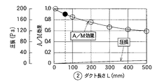
図19は、図17(b)に示すように衝突角度θ=0°の条件において冷温風混合部M2 の後流側のダクト長さLを変化させたときのA/M効果の変化を示す。このダクト長さLの増加によりA/M効果(ΔT2 /ΔT)の比が低下して、冷温風の混合性を向上できる。
図20は、図17(c)に示すように衝突角度θ=0°の条件において冷温風混合部の後流側のダクト曲がり角αを変化させたときのA/M効果の変化を示す。このダクト曲がり角αの増加によりA/M効果(ΔT2 /ΔT)の比が低下して、冷温風の混合性を向上でき、特に、曲がり角α=90°にて、A/M効果の比を0.6以下まで低下でき、冷温風の混合効果が顕著となる。
【0094】
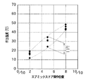
図21は、上記図18〜図20の効果を総合した結果を示すもので、衝突角度θ=180°、ダクト長さL=60mm、およびダクト曲がり角α=90°を組み合わせた場合における車室内への吹出空気温度と、エアミックスドア操作位置との関係を示すデータである。ここで、横軸のエアミックスドア操作位置=0/10は、冷風通路15、16、30を全開し、ヒータコア8の通風路を全閉する最大冷房位置であり、エアミックスドア操作位置=10/10は冷風通路15、16、30を全閉し、ヒータコア8の通風路を全開する最大暖房位置である。図21の横軸はエアミックスドア操作位置を0/10と10/10との間を5分割している。
【0095】
図21に示すように、エアミックスドア操作位置=2/10〜8/10の範囲において、車室内への吹出空気温度のバラツキを10°以内に抑えることができるという良好な結果を得ることができた。
図15は、上記実験結果に基づいて構成した、第3実施形態によるフット側の冷温風混合部の具体的形態を例示(車両左右方向の片側のみ図示)しており、車両左右方向の中央部に位置するフット開口部25a(図1〜図3等参照)からの温風が流れる温風通路31を車両左右方向に沿って形成した後、その端部31aを上方へ屈折させている。
【0096】
一方、フット用冷風通路15、16からの冷風は第1、第2実施形態と同様にヒータコア8の車両左右方向においてヒータコア8の上方部を通過した後にヒータコア8の下側へ向かって流れる。そのため、フット用冷風通路15、16の下端部と、温風通路31の上方への屈折端部31aとを180°逆方向から対向配置することができる。
【0097】
従って、フット用冷風通路15、16の下端部と、温風通路31の上方への屈折端部31aとの合流部に、冷風Dと温風Cとを衝突角度θ=180°にて略対向状に衝突させるフット用冷温風混合部M2 を構成することができる。なお、図15では図示形状の簡素化のために、車両左右方向の左右のフット開口部25b、25cの図示を省略しているが、上記冷温風混合部M2 の直ぐ上方部位に左右のフット開口部25b、25cは配置され、第2フットドア27b、27c(図15では図示省略)により開閉される。
【0098】
そして、冷温風混合部M2 にて冷温風を混合した空気は、冷温風混合部M2 の直ぐ側方に位置する冷温風出口32を通過して吹出ダクト33を通過する。この吹出ダクト33は、冷温風出口32からの空気流れを矢印Jのごとく下方へ直角状に曲げる形状にしてあり、この吹出ダクト33により図17(c)の略直角状のダクト曲がり部を構成することができる。
【0099】
吹出ダクト33の下端部は空気を車室内の乗員の足元部に吹き出すフット開口部28、29を構成するので、この吹出ダクト33により図17(b)に示すダクト長さLを設定することができる。
(第4実施形態)
図22は第4実施形態であり、第1実施形態で説明した空調ユニット1の車両搭載状態を示すもので、空調ユニット1は前述したように偏平横長形状(例えば、W寸法=460mm、H寸法=250mm、L寸法=230mm)であるため、空調ケース2の上面部に配置されるデフロスタ開口部23およびフェイス開口部24についても横長形状であることを利用して、車両前後方向の寸法を小さくしても、必要な開口面積を確保することができる。
【0100】
そのため、空調ケース2の上面部においてデフロスタ開口部23およびフェイス開口部24を車両後方寄りの部位に配置できる。これにより、デフロスタ開口部23の車両前方側に、下側への段付き形状部34を空調ケース2の上面部に形成できる。
一方、車両側においては、空調ユニット1の車両前方側の部位において、カウルパネル35の内側パネル36を車両後方側へ突出させる形態として、カウルパネル35と内側パネル36との間の空間37を車両前後方向に拡大して、この空間37内にワイパーリンク機構38等の車両側機器を搭載することができる。
【0101】
ここで、第4実施形態の搭載形態によると、空調ケース2の上面部の前方側に下側への段付き形状部34を形成しているので、内側パネル36が車両後方側へ大きく突出しても、この突出形状と空調ケース2の上面部とが干渉することを容易に回避できる。
なお、図22において、39は車室内とエンジンルームとを仕切るダッシュパネル、40は車室のフロアパネル、41は車室内乗員の足部、42は計器盤である。
【0102】
(第5実施形態)
図23は第5実施形態であり、上述の第1〜第4実施形態では、フット開口部28、29およびデフロスタ開口部23の両方を同時に開口するフットモードおよびフットデフロスタモードにおいて、フット開口部28、29には内気が流れ、デフロスタ開口部23には外気が流れる内外気2層流モードを設定しているが、第5実施形態ではこのような内外気2層流モードを設定しない空調ユニット1に関する。
【0103】
第1〜第4実施形態では、中央部の第1フットドア27aは図3、図5に示すように、フットモード時およびフットデフロスタモード時にフット開口部25aの開放位置に操作されるとともに、第1フットドア27aの先端部が仕切り板14に当接することにより、ヒータコア8の下流側において、空気通路を外気側の第1空気通路9と内気側の第2空気通路10とに仕切る仕切り部材の役割を兼ねている。
【0104】
そのため、第1フットドア27aは必然的にヒータコア8の下流直後の温風通路中に配置する必要があるので、第1フットドア27aが温風通路の通風抵抗を増大させて、温風量を減少させる。
一方、第5実施形態は内外気2層流モードを設定しない空調ユニット1に関するため、第1フットドア27aに内外気の仕切り部材の役割を兼務させる必要がない。そこで、中央部の第1フットドア27aおよび左右両側の第2フットドア27b、27cをフット開口部25a、25b、25cより下流側の空気混合室26、すなわち、フット開口部28、29の入口側に配置している。
【0105】
これにより、ヒータコア8の下流直後の温風通路43から、空気流れの妨げとなるフットドアを廃止でき、温風通路43の通風抵抗を減少させて、温風量を増加できる。
なお、第5実施形態では内外気2層流モードを設定しないので、仕切り板6、13、14(図3等参照)を廃止している。
【0106】
また、第1〜第4実施形態では、エアミックスドア11、12として、平板に近似した大きな曲率半径を持つ円弧状の板部材からなるドアを用い、このエアミックスドア11、12を概略車両上下方向に摺動可能に配置しているが、第5実施形態ではエアミックスドア11、12として、空気流れ方向(車両前後方向)の中間部に車両左右方向に延びる回転軸11a、12aを有し、この回転軸11a、12aを中心として回動可能なバタフライドアを用いている。
【0107】
(他の実施形態)
なお、上記実施形態では、セミセンター置きレイアウトの空調ユニットについて説明したが、送風機部を空調ユニット部の車両前方側に配置した完全センター置きレイアウトの空調ユニットに本発明を適用できることはもちろんである。さらに、本発明は、車室内前方の計器盤内に配置される空調ユニットだけでなく、車両の他の部位に搭載される空調ユニットに対しても適用可能である(請求項18の発明)。
【図面の簡単な説明】
【図1】本発明の第1実施形態による空調ユニットの概略正面図である。
【図2】図1の空調ユニットの概略平面図である。
【図3】図1、2の空調ユニットの縦断面図である。
【図4】図1、2の空調ユニットの縦断面図である。
【図5】図1、2の空調ユニットの縦断面図である。
【図6】図1、2の空調ユニットの縦断面図である。
【図7】図1、2の空調ユニットの縦断面図である。
【図8】図1、2の空調ユニットの縦断面図である。
【図9】図1、2の空調ユニットの縦断面図である。
【図10】本発明の第2実施形態による空調ユニットの概略斜視図である。
【図11】(a)は図10のデフロスタ開口部周辺の部分側面図、(b)は(a)の部分正面図である。
【図12】第2実施形態による空調ユニットの概略正面図である。
【図13】図12の空調ユニットの概略平面図である。
【図14】第2実施形態で用いる蒸発器の正面図である。
【図15】第3実施形態によるフット側冷温風混合機構を示す要部の概略斜視図である。
【図16】第1、第2実施形態によるデフロスタ、フェイス側の冷温風混合機構およびフット側の冷温風混合機構を示す概略斜視図である。
【図17】第3実施形態による冷温風混合性の実験方法の説明図である。
【図18】第3実施形態による冷温風の衝突角度と混合性の実験結果のグラフである。
【図19】第3実施形態による冷温風のダクト長さと混合性の実験結果のグラフである。
【図20】第3実施形態による冷温風のダクト曲がり角度と混合性の実験結果のグラフである。
【図21】第3実施形態による吹出温度バラツキの実験結果のグラフである。
【図22】第4実施形態による空調ユニットの車両搭載状態の断面図である。
【図23】第5実施形態による空調ユニットの断面図である。
【符号の説明】
2…ケース、4、5、9、10…空気通路、7…蒸発器、8…ヒータコア、
11、12…エアミックスドア、15、16…フット用冷風通路、
23…デフロスタ開口部、24…フェイス開口部、
25a〜25c、28、29…フット開口部、26…フット用空気混合室、
30…デフロスタ・フェイス用冷風通路。[0001]
BACKGROUND OF THE INVENTION
The present invention relates to a vehicle air conditioner that has improved mountability in the instrument panel at the front of a vehicle interior.
[0002]
[Prior art]
Conventionally, in an air conditioner for a vehicle, when an air conditioning unit is arranged near the instrument panel in the front part of the vehicle interior, an air conditioning unit including a cooling evaporator, a heater core, a blow mode switching mechanism, etc. A semi-centered layout has been put into practical use in which a blower unit that blows conditioned air to the air conditioning unit is offset to the passenger seat side on the side of the air conditioning unit while being arranged at a substantially central portion in the vehicle left-right direction.
[0003]
In addition, a complete center placement layout in which the blower unit is disposed on the vehicle front side of the air conditioning unit unit has been partially put into practical use.
In both the conventional semi-center layout and the complete center layout, a cold air passage that bypasses the heater core is usually arranged above the heater core (heating heat exchanger) in the vehicle mounted state, and the face mode and In both foot modes, the temperature of the blown air is adjusted by adjusting the air volume ratio of the cold and warm air using a common cold air passage and a common air mixing chamber.
[0004]
[Problems to be solved by the invention]
By the way, in order to increase the amount of cold air at the maximum cooling, in general, the shape of the cold air passage and the air mixing chamber in the air conditioning unit is designed with priority given to reducing the pressure loss in the face mode. Often results in a refracted shape, leading to an increase in pressure loss.
[0005]
The present invention has been made in view of the above points, and an object of the present invention is to achieve both a reduction in pressure loss during the foot mode of a vehicle air conditioner and an improvement in mountability in a vehicle instrument panel.
[0006]
[Means for Solving the Problems]
In order to achieve the above object, according to the first aspect of the present invention, in the case (2) forming the air passage (4, 5, 9, 10), the cooling heat exchanger (7) is provided at the front side of the vehicle. In the case (2), a heating heat exchanger (8) is arranged behind the cooling heat exchanger (7) in the vehicle, and is heated by passing through the heating heat exchanger (8). The temperature adjustment means (11, 12) adjusts the air volume ratio between the warm air and the cold air bypassing the heating heat exchanger (8) to adjust the temperature of the air blown into the passenger compartment. Air whose temperature has been adjusted by the adjusting means (11, 12)Formed on the upper surface of the case (2)The face opening (24) that blows out to the head of the occupant and the temperature-adjusted air by the temperature adjusting means (11, 12), Formed on the bottom side of the case (2)In a vehicle air conditioner comprising a foot opening (28, 29) that blows out to the feet of the passenger,
From the cold air passage (30) for bypassing the cold air from the heat exchanger (7) for cooling to the face opening (24), bypassing the heat exchanger (8) for heating, and from the heat exchanger (7) for cooling A cold air passage for the foot (15, 16) that bypasses the heat exchanger (8) for heating and leads the foot opening (28, 29) independently,
The cold air passage for the face (30) is formed so as to pass through the upper side of the heat exchanger for heating (8) toward the face opening (24), and the cold air from the cold air passage for the face (30) can be heated. The hot air that has passed through the heat exchanger (8) for use at the inlet side of the face opening (24),
The foot cool air passages (15, 16) pass through the upper side of the heating heat exchanger (8) on the side of the heating heat exchanger (8) in the left-right direction of the vehicle, and then the heating heat exchanger (8 ) Is formed so as to bend downward, and the cool air from the cool air passage for the foot (15, 16) and the warm air that has passed through the heating heat exchanger (8) are connected to the foot opening (28, 29). ) Mixing at the inlet side
The opening degree of the cold air passage for face (30) and the opening degree of the cold air passage for feet (15, 16) are adjusted by a common temperature adjusting means (11, 12).It is characterized by that.
[0007]
According to this, the temperature of the air blown out from the face opening (24) and the foot openings (28, 29) can be satisfactorily controlled by adjusting the air volume ratio of the cool / warm air.
Moreover, the cold air passage for the foot (15, 16) is formed independently from the cold air passage for the face (30), and cold air is mixed on the inlet side of the foot opening (28, 29). A shape that reaches the inlet side of the foot openings (28, 29) in a short distance with little bending in the hot air passage downstream of the heating heat exchanger (8) without being restricted by the form of the cold air passage (30) It can be. Thereby, the pressure loss at the time of foot mode can be reduced, and the air volume at the time of foot mode can be increased.
[0008]
Further, when the cold air passage for the face (30) and the cold air passage for the foot (15, 16) are formed independently, the cold air passage for the foot (15, 16) is particularly provided in the left-right direction of the heating heat exchanger (8). Therefore, the foot cool air passages (15, 16) can be shifted from the face cold air passage (30) in the left-right direction of the vehicle. For this reason, it can suppress effectively that the vehicle vertical direction dimension of the whole case of an air-conditioning unit increases. Further, since the warm air passage downstream of the heating heat exchanger (8) can be led directly to the entrance side of the foot opening (28, 29) without bending in the vehicle vertical direction, the vehicle longitudinal dimension Can also be shortened. Together, these can improve the mountability of the air conditioning unit in the center of the vehicle instrument panel.
Further, since the cold air passage for face (30) and the cold air passage for feet (15, 16) are both located above the heating heat exchanger (8) in the vehicle vertical direction, both cold air passages (30 , 15, 16) can be adjusted by the common temperature adjusting means (11, 12), and the configuration can be simplified.
[0009]
In the invention according to
[0010]
according to this,The opening degree of the cold air passage for face (30) and the cold air passage for feet (15, 16) can be adjusted by the common first door (11).
[0011]
In the invention according to
According to this, the cold air can be directly introduced into the entrance side of the foot openings (28, 29) on both sides in the left and right direction through the cold air passages (15, 16) on the left and right sides.
[0012]
In the invention according to
[0013]
According to this, it is possible to arrange the foot cool air passages (15, 16) by effectively using the surplus space generated on the side of the heating heat exchanger (8) in the left-right direction of the vehicle, and the physique of the entire case of the air conditioning unit is effective. Can be miniaturized.
Moreover, the vertical dimension of the cooling heat exchanger (7) is increased by increasing the width dimension (W) of the cooling heat exchanger (7) in the left-right direction of the vehicle relative to the heating heat exchanger (8). And the vertical dimension of the entire case of the air conditioning unit can be reduced.
[0014]
Furthermore, by expanding the width dimension (W) of the vehicle heat exchanger (7) in the left-right direction of the vehicle, the face-shaped (cooling) time-effective shape of the cooling heat exchanger (7) is effectively utilized. A wide range of cool air can be blown out toward the upper body of the occupant, improving the cooling feeling by increasing the sensation of the cool air flow to the occupant, and at the same time reducing the bending of the cold air and reducing the pressure loss in the face mode. Can do.
[0015]
Moreover, in invention of
W0= 0.6 to 0.8 × W is set.
According to this, the foot cold air passages (15, 16) are located laterally in the vehicle left-right direction of the heating heat exchanger (8) and the width dimension (W in the vehicle left-right direction of the cooling heat exchanger (7)). ) Even in the layout arranged within the range of0Is set to 0.8 × W or less, the width of the cool air passage for the foot (15, 16) can be sufficiently secured, and the amount of cool air necessary for foot blow temperature control can be secured. Controllability can be established. W0By making it = 0.6 × W or more, the necessary heat transfer area of the heating heat exchanger (8) can be secured, and the necessary heating capacity of the heating heat exchanger (8) can be secured.
[0016]
Further, in the invention described in
[0017]
According to this, the cool and warm air collides in a substantially opposite shape from the direction of 180 ° and is mixed well. Further, after the collision, the steep air also passes through the substantially right-angled duct bending portion (33). Cold and warm air can be mixed well using bending. Therefore, the temperature variation of the air blown out from the foot opening (28, 29) into the vehicle compartment can be reduced.
[0018]
Further, as in the invention described in
The invention according to
[0019]
According to this, since the refrigerant flows through the refrigerant passage in the tube (71) in the vertical direction of the vehicle, even if the cooling heat exchanger (7) has a horizontally long shape, the blowing temperature can be made uniform in the horizontal direction of the vehicle.
Moreover, in invention of
The cooling heat exchanger (7) has a width dimension (W) in the vehicle left-right direction equivalent to the horizontally long case (2),Defroster opening (23)Vehicle width in the left-right direction (W2) Is made smaller than the width dimension (W) in the vehicle left-right direction of the cooling heat exchanger (7).
[0020]
Thus, cooling heat exchanger width dimension (W)>Defroster opening (23)Width dimension (W2), The cool air after the cooling heat exchanger (7)Defroster opening (23)It is possible to suppress the flow too much. As a result, the amount of cool air after the cooling heat exchanger (7) flows to the foot openings (28, 29) through the foot cool air passages (15, 16) is increased, and the foot blowing air temperature is excessively increased. It is possible to satisfactorily suppress the rise, to properly set the upper and lower blowing temperature difference, and to improve the air conditioning feeling.
[0021]
In the invention according to
[0022]
According to this, the effect of the invention of
If the defroster opening (23) and the face opening (24) are arranged in the center of the case (2) in the left-right direction of the vehicle as in the invention described in
[0023]
Further, in the invention described in
[0024]
According to this, it becomes easy to avoid the interference with the vehicle side equipment by using the stepped shape portion (34) on the lower side in the vehicle front side portion of the upper surface portion of the case (2). Vehicle mountability can be further improved.
According to a thirteenth aspect of the present invention, in any one of the ninth to twelfth aspects, in the blowing mode in which both the foot opening (28, 29) and the defroster opening (23) are simultaneously opened, the foot opening (28, 29) is characterized in that the inside air flows in the defroster opening (23) and the inside / outside air two-layer flow mode in which the outside air flows is set.
[0025]
As described above, the present invention can satisfactorily exert the functions and effects of the claims even when the inside / outside air two-layer flow mode is set.
In the invention described in
[0026]
According to this, even with the layout in which the cold air passages for foot (15, 16) are arranged in the vehicle lateral direction side of the heating heat exchanger (8), the two foot doors (27a, 27b, 27c) By controlling the flow of the cool air and the warm air, the cool air and the warm air can be mixed on the downstream side of the door (that is, the inlet side of the foot openings (28, 29)).
Moreover, if the 1st foot door (27a) is located immediately after the heat exchanger for heating (8) like invention of
[0027]
Moreover, if the 1st foot door (27a) is located in the entrance side of a foot opening part (28, 29) like invention of
Further, as in the invention described in
[0028]
Furthermore, in the invention described in
From the cold air passage (30) for bypassing the cold air from the heat exchanger (7) for cooling to the face opening (24), bypassing the heat exchanger (8) for heating, and from the heat exchanger (7) for cooling A cold air passage for the foot (15, 16) that bypasses the heat exchanger (8) for heating and leads the foot opening (28, 29) independently,
The cold air passage for the face (30) is formed so as to pass through the upper side of the heat exchanger for heating (8) toward the face opening (24), and the cold air from the cold air passage for the face (30) can be heated. The hot air that has passed through the heat exchanger (8) for use at the inlet side of the face opening (24),
The foot cool air passages (15, 16) pass on the both sides of the heating heat exchanger (8) and then pass above the heating heat exchanger (8) and then to the lower side of the heating heat exchanger (8). The cool air from the cool air passage for the foot (15, 16) and the warm air that has passed through the heating heat exchanger (8) are formed on the inlet side of the foot opening (28, 29). Mixed,
The opening degree of the cold air passage for face (30) and the opening degree of the cold air passage for feet (15, 16) are adjusted by a common temperature adjusting means (11, 12).It is characterized by that.
[0029]
Also by this, the foot cold air passage (15, 16) independent of the face cold air passage (30) is arranged on the lateral side of the heating heat exchanger (8), and The same effect can be exhibited.
As in the invention described in
Further, as in the twentieth aspect of the invention, in the vehicular air conditioner according to the twentieth aspect, the foot cool air passage (15, 16) bends toward the lower side of the heating heat exchanger (8). You may form a part in the both sides of the warm air path which passes a heat exchanger for heating (8) and goes to a face opening part (24).
In addition, the code | symbol in the bracket | parenthesis of each said means shows a corresponding relationship with the specific means of embodiment description later mentioned.
[0030]
DETAILED DESCRIPTION OF THE INVENTION
Hereinafter, embodiments of the present invention will be described with reference to the drawings.
(First embodiment)
FIG. 1 is a front view of an
[0031]
Next, the vehicle-mounted form of the
[0032]
Next, the specific configuration of the
[0033]
As shown in FIG. 2, an
[0034]
As shown in cross-sectional views of FIGS. 3 to 9 described later, the
The blower unit has a well-known configuration, and an internal / external air switching mechanism that switches between introducing outside air from the outside air inlet (inside air of the passenger compartment) and inside air from the inside air inlet (inside of the passenger compartment), and the outside air inlet. It is comprised from the air blower which ventilates the intake air from an inside air inlet. This blower has a first fan on the outside air side and a second fan on the inside air side, and in the inside / outside air two-layer flow mode, the outside air and the inside air can be divided and blown simultaneously by the first fan and the second fan. It has become.
[0035]
Note that the inside / outside air two-layer flow mode is the maximum heating in the blowing mode in which air is blown out from both a foot opening and a defroster opening, which will be described later, and warm air of low humidity is blown out from the defroster opening. A mode in which the antifogging property is ensured and at the same time the hot air of the recirculated inside air is blown out from the foot opening to enhance the heating effect of the passenger's feet.
[0036]
In the inside / outside air two-layer flow mode, outside air from the first fan flows into the
On the other hand, air (outside air) passes through the
[0037]
In this example, the
[0038]
As shown in FIG. 3 and the like, the
Two air mix doors (temperature adjusting means) are provided immediately downstream of the evaporator 7 (the vehicle rear side)., 1st door, 2nd door) 11 and 12 are arranged adjacent to each other so as to be slidable substantially in the vehicle vertical direction. The
[0039]
A link mechanism (not shown) is connected to one of the lateral end portions of the arc-shaped plate members constituting the
[0040]
The
[0041]
The
The
[0042]
Next, the passage configuration of the hot air and the cold air in which the air volume ratio is adjusted by the
[0043]
On the other hand, the dimension W of the
[0044]
Further, between the
[0045]
Here, in FIG. 4, a two-dot chain line D indicates the cold air flow by the
Next, the blowing mode switching mechanism in the present embodiment will be described. A plurality of blowing openings are formed on the downstream side of the air passage of the
[0046]
Next, the
[0047]
Next, the
[0048]
And foot opening 25b, 25c is arrange | positioned corresponding to the
The three
[0049]
As shown in FIG. 3, the central foot door (first foot door) 27a is operated to the open position of the
[0050]
The
[0051]
Since the air mixing chamber 26 (FIG. 3 and the like) forms one communicating space in the vehicle left-right direction, the warm air from the
[0052]
On the other hand, the defroster / face
[0053]
Next, the operation of the present embodiment in the above configuration will be described for each blowing mode.
"Foot blowing mode"
FIG. 3 shows the maximum heating state in the foot blowing mode, and the
[0054]
On the other hand, the upper and lower
[0055]
Further, at this time, in the blower unit (not shown), since the inside / outside air two-layer flow mode for sucking both the inside air and the outside air is selected by the inside / outside air switching mechanism, the operation of the first and second fans of the blower unit Outside air flows into the
Then, after the outside air in the
[0056]
Since the downstream side passage of the
[0057]
On the other hand, the warm air of the inside air passes through the
Further, in the maximum heating state, the warm air of the inside air changes in the direction immediately below the lower part of the
[0058]
As described above, it is possible to achieve both the improvement of the heating effect of the passenger's feet and the securing of the antifogging property of the vehicle window glass.
Next, FIG. 4 shows the temperature control state in the foot blowing mode, and the two
[0059]
As a result, the warm air that has passed through the lower side of the
[0060]
Accordingly, in the
Further, the warm air that has passed through the upper side of the
[0061]
The temperature of the hot air blown to the passenger's feet and the window glass can be arbitrarily adjusted by adjusting the operation positions of the
Further, in the temperature control state of the foot blowing mode, the forms of the
[0062]
In the temperature control state, priority is given to ensuring the ventilation function of the passenger compartment and the anti-fogging property of the window glass over the heating capacity, and the intake mode of the inside and outside air is usually the all outside air mode (that is, the first air passage 4). , 9 and the
"Foot defroster blowing mode"
FIG. 5 shows the maximum heating state in the foot defroster blowing mode, which is different from the maximum heating state in the foot blowing mode in FIG. 3 in that the
[0063]
In the foot blowing mode, the ratio of the foot-side blowing amount and the defroster-side blowing amount is usually about 8 to 2. The ratio with the air volume is about 5 to 5. Since other points are the same as the foot defroster blowing mode, the description is omitted.
[0064]
"Defroster blowing mode"
FIG. 6 shows the maximum heating state in the defroster blowing mode. The
[0065]
Therefore, the warm air that has passed through the upper and lower sides of the
[0066]
Although the illustration of the temperature control state in the defroster blowing mode is omitted, as with the temperature control state in the foot blowing mode and the foot defroster blowing mode described above, the operation position of the
[0067]
In the defroster blowing mode, in order to ensure window glass anti-fogging properties, the all outside air mode is normally selected as the inside and outside air suction mode.
"Face blowing mode"
FIG. 7 shows the maximum cooling state in the face blowing mode. The
[0068]
In the maximum cooling state, the two
[0069]
However, even if the foot
By operating the refrigeration cycle for vehicle air conditioning and absorbing the evaporation latent heat of the refrigerant from the blown air in the
[0070]
In the maximum cooling state, in order to improve the cooling capacity, the inside / outside air suction mode is usually the whole inside air mode (that is, the inside air is introduced into both the
FIG. 8 shows a temperature control state in the face blowing mode, which is different in that the two
[0071]
As a result, the warm air that has passed through the
[0072]
In the temperature control state, in order to secure the ventilation function, the semi-inside air mode or the all outside air mode in which the outside air is mixed with the outside air is usually selected as the inside / outside air suction mode.
"Bi-level blowing mode"
FIG. 9 shows the bi-level blowing mode, and the
[0073]
The two
[0074]
At the same time, the warm air indicated by the arrow C that has passed through the lower side of the
[0075]
In the bi-level blowing mode, in order to secure the ventilation function, the semi-inside air mode or the full outside air mode is normally selected as the inside / outside air suction mode.
Next, the concept of the specific design of the present embodiment will be described. The width dimension W in the vehicle left-right direction of the air conditioning unit 1 (evaporator 7) is 460 mm as described above. Width dimension W0Is about 70% of W, specifically 300 mm.
[0076]
The inventors have determined that these width dimensions W, W0When we examined the relationship between0It was found that setting to = 0.6 to 0.8 × W is preferable for establishing controllability of the foot blowing temperature and for securing the heating capability of the
That is, W0= 0.8 x W or more W0Is increased, the width dimension W in the vehicle left-right direction of the
[0077]
W0= 0.6 x W or less W0If W = 460 mm, W0= 460 mm x 0.6 = 276 mm, W1= (460mm-276mm) / 2 = 92mm, W1Can secure a sufficient size, but on the other hand, the width W of the
[0078]
For the above reasons, W0= 0.6 to 0.8 × W is preferable for establishing controllability of the foot blowing temperature and for securing the heating capability of the
(Second Embodiment)
10 to 14 show a second embodiment. In the first embodiment, as shown in FIG. 2, the vehicle left-right dimension of the
[0079]
As a result, the amount of cold air flowing into the foot
Therefore, in the second embodiment, as shown in FIGS. 10 to 13, the dimension W of the
[0080]
In this example, the
Here, the rotation space of the
[0081]
Accordingly, the cold air that has passed through the
As a result, the amount of cold air flowing into the foot
[0082]
Moreover, since the
[0083]
In addition, since the
FIG. 14 shows a specific example of the
[0084]
Here, the
[0085]
In addition, the left end of the
[0086]
In the
(Third embodiment)
FIG. 15 shows a third embodiment, which improves the mixability of cold and warm air on the foot side in the first and second embodiments.
[0087]
FIG. 16 is an explanatory view showing the cold and hot air mixing mode in the first and second embodiments, and arrows E, F, and G pass through the defroster face
[0088]
On the other hand, the arrow D indicates the foot mixing portion M at the
[0089]
By the way, when the prototype of the mixed form of the cold / hot air in FIG. 16 is actually examined, the mixing characteristics of the cold / hot air on the foot side greatly change depending on the design specification of the mixed form, and the foot opening28, 29It was found that the temperature variation of the air blown from the air fluctuated greatly.
18 to 21 show the results of experiments conducted by the present inventors, and FIG. 17 is a diagram for explaining the method of this experiment. FIG. 17A shows the collision angle θ on the horizontal axis of FIG. The intersection angle at which the flow path of the hot air C and the flow path of the cold air D in FIG. 16 intersect is defined as the cold / hot air collision angle θ. Here, as experimental conditions, hot air C = 65 ° C., cold air D = 5 ° C., and temperature difference ΔT between the two.1= 60 ° C.
[0090]
Further, after the flow path of the hot air C and the flow path of the cold air D intersect (in other words, the mixing section M of the cold and hot air)2), And the relationship between the A / M effect and the collision angle θ when the duct length L = 100 mm to the
Here, the A / M effect is an index of the mixability of the cool and warm air, and the temperature difference between the cool and warm air before mixing is expressed as ΔT.1And the difference (temperature variation) between the minimum and maximum temperatures of the air blown into the passenger compartment2A / M effect = ΔT2/ ΔT1It is represented by
[0091]
As understood from the result of FIG. 18, by increasing the collision angle θ from 0 ° to 180 °, the A / M effect (ΔT2/ ΔT1) Ratio is gradually decreased, and the mixing of cold and hot air can be improved. In particular, at the collision angle θ = 180 °, ΔT2/ ΔT1Can be reduced to near 0.2. This means that the temperature variation of the air blown into the passenger compartment can be reduced to about 12 ° C.
[0092]
The warm air C and the cold air D collide with each other as the collision angle θ increases, so that the pressure loss of the air passage of the entire air conditioning unit increases to some extent, but the increase level is not so high. There is no practical problem. Further, in FIG. 18, the collision angle θ = 90 ° indicates the case of the cold / hot air mixed form on the foot side in the first and second embodiments.
[0093]
FIG. 19 shows the cold / hot air mixing unit M under the condition of the collision angle θ = 0 ° as shown in FIG.2The change of the A / M effect when changing the duct length L on the wake side is shown. By increasing the duct length L, the A / M effect (ΔT2/ ΔT) ratio can be reduced, and the mixing of cold and hot air can be improved.
FIG. 20 shows the change of the A / M effect when the duct bending angle α on the downstream side of the cold / hot air mixing unit is changed under the condition of the collision angle θ = 0 ° as shown in FIG. By increasing the duct bending angle α, the A / M effect (ΔT2/ ΔT) ratio can be reduced to improve the mixing of cold and hot air, and in particular, at the turning angle α = 90 °, the A / M effect ratio can be reduced to 0.6 or less, and the mixing effect of cold and hot air can be reduced. Become prominent.
[0094]
FIG. 21 shows a result obtained by integrating the effects of FIGS. 18 to 20. The vehicle interior when the collision angle θ = 180 °, the duct length L = 60 mm, and the duct bending angle α = 90 ° are combined. It is the data which shows the relationship between the blowing air temperature and air mix door operation position. Here, the air mix door operation position = 0/10 on the horizontal axis is the maximum cooling position in which the
[0095]
As shown in FIG. 21, in the range of the air mix door operation position = 2/10 to 10/10, it is possible to obtain a good result that the variation in the temperature of the air blown into the vehicle interior can be suppressed within 10 °. did it.
FIG. 15 exemplifies a specific form of the foot-side cold / warm air mixing unit according to the third embodiment, which is configured based on the above experimental results (only one side in the vehicle left-right direction is shown), and the center part in the vehicle left-right direction After the
[0096]
On the other hand, the cool air from the foot
[0097]
Accordingly, the cold air D and the hot air C are substantially opposed at the collision angle θ = 180 ° at the junction between the lower ends of the
[0098]
And cold / hot air mixing part M2The air mixed with cold and warm air at2It passes through the
[0099]
Since the lower end portion of the blowing
(Fourth embodiment)
FIG. 22 shows the fourth embodiment, which shows the vehicle-mounted state of the
[0100]
For this reason, the
On the other hand, on the vehicle side, the
[0101]
Here, according to the mounting form of the fourth embodiment, since the stepped
In FIG. 22, 39 is a dash panel that partitions the vehicle compartment from the engine compartment, 40 is a floor panel of the vehicle compartment, 41 is a foot of a passenger in the vehicle interior, and 42 is an instrument panel.
[0102]
(Fifth embodiment)
FIG. 23 shows a fifth embodiment. In the first to fourth embodiments described above, the
[0103]
In the first to fourth embodiments, as shown in FIGS. 3 and 5, the
[0104]
For this reason, the
On the other hand, since the fifth embodiment relates to the
[0105]
Thereby, the foot door which obstructs an air flow can be abolished from the
In the fifth embodiment, since the inside / outside air two-layer flow mode is not set, the
[0106]
In the first to fourth embodiments, as the
[0107]
(Other embodiments)
In the above-described embodiment, the air conditioning unit having the semi-center layout is described. However, it is needless to say that the present invention can be applied to an air conditioning unit having a complete center layout in which the blower unit is disposed on the vehicle front side of the air conditioning unit. Furthermore, the present invention can be applied not only to an air conditioning unit disposed in an instrument panel in front of the vehicle interior, but also to an air conditioning unit mounted in another part of the vehicle (claims).18Invention).
[Brief description of the drawings]
FIG. 1 is a schematic front view of an air conditioning unit according to a first embodiment of the present invention.
FIG. 2 is a schematic plan view of the air conditioning unit of FIG.
FIG. 3 is a longitudinal sectional view of the air conditioning unit of FIGS.
4 is a longitudinal sectional view of the air conditioning unit of FIGS.
FIG. 5 is a longitudinal sectional view of the air conditioning unit of FIGS.
6 is a longitudinal sectional view of the air conditioning unit of FIGS.
7 is a longitudinal sectional view of the air conditioning unit of FIGS.
8 is a longitudinal sectional view of the air conditioning unit of FIGS.
FIG. 9 is a longitudinal sectional view of the air conditioning unit of FIGS.
FIG. 10 is a schematic perspective view of an air conditioning unit according to a second embodiment of the present invention.
11A is a partial side view of the periphery of the defroster opening of FIG. 10, and FIG. 11B is a partial front view of FIG.
FIG. 12 is a schematic front view of an air conditioning unit according to a second embodiment.
13 is a schematic plan view of the air conditioning unit of FIG.
FIG. 14 is a front view of an evaporator used in the second embodiment.
FIG. 15 is a schematic perspective view of a main part showing a foot-side cold / hot air mixing mechanism according to a third embodiment.
FIG. 16 is a schematic perspective view showing a defroster, a cold / hot air mixing mechanism on the face side, and a cold / hot air mixing mechanism on the foot side according to the first and second embodiments.
FIG. 17 is an explanatory diagram of a cold / hot air mixing test method according to a third embodiment.
FIG. 18 is a graph showing the experimental results of the cold-hot air collision angle and mixing properties according to the third embodiment.
FIG. 19 is a graph showing experimental results of duct length and mixing properties of cold and hot air according to the third embodiment.
FIG. 20 is a graph showing experimental results of duct bend angle and mixing properties of cold and hot air according to the third embodiment.
FIG. 21 is a graph showing an experimental result of blowout temperature variation according to the third embodiment.
FIG. 22 is a cross-sectional view of an air conditioning unit mounted on a vehicle according to a fourth embodiment.
FIG. 23 is a sectional view of an air conditioning unit according to a fifth embodiment.
[Explanation of symbols]
2 ...
11, 12 ... Air mix door, 15, 16 ... Cool air passage for foot,
23: Defroster opening, 24 ... Face opening,
25a-25c, 28, 29 ... foot opening, 26 ... air mixing chamber for foot,
30 ... Cool air passage for defroster face.
Claims (20)
車両前方側から車両後方側へ向かって空気が流れる空気通路(4、5、9、10)を形成するケース(2)と、
このケース(2)内において車両前方側の部位に配置され、空気を冷却する冷房用熱交換器(7)と、
前記ケース(2)内において前記冷房用熱交換器(7)よりも車両後方側に配置され、空気を加熱する暖房用熱交換器(8)と、
この暖房用熱交換器(8)を通過して加熱される温風とこの暖房用熱交換器(8)をバイパスする冷風との風量割合を調整して、車室内への吹出空気温度を調整する温度調整手段(11、12)と、
前記ケース(2)の上面部に形成され、前記温度調整手段(11、12)により温度調整された空気を乗員の頭部側へ吹き出すフェイス開口部(24)と、
前記ケース(2)の底面側に形成され、前記温度調整手段(11、12)により温度調整された空気を乗員の足元側へ吹き出すフット開口部(28、29)とを備える車両用空調装置において、
前記冷房用熱交換器(7)からの冷風を前記暖房用熱交換器(8)をバイパスして前記フェイス開口部(24)に導くフェイス用冷風通路(30)と、前記冷房用熱交換器(7)からの冷風を前記暖房用熱交換器(8)をバイパスして前記フット開口部(28、29)に導くフット用冷風通路(15、16)とを独立に形成し、
前記フェイス用冷風通路(30)は、前記暖房用熱交換器(8)の上側を通過して前記フェイス開口部(24)に向かうように形成されており、前記フェイス用冷風通路(30)からの冷風と前記暖房用熱交換器(8)を通過した温風とを前記フェイス開口部(24)の入口側で混合し、
前記フット用冷風通路(15、16)は、前記暖房用熱交換器(8)の車両左右方向の側方において、前記暖房用熱交換器(8)の上側を通過した後に、前記暖房用熱交換器(8)の下側へ向かって曲がるように形成されており、前記フット用冷風通路(15、16)からの冷風と前記暖房用熱交換器(8)を通過した温風とを前記フット開口部(28、29)の入口側で混合し、
前記フェイス用冷風通路(30)の開度および前記フット用冷風通路(15、16)の開度を共通の前記温度調整手段(11、12)により調整することを特徴とする車両用空調装置。A vehicle air conditioner disposed in the instrument panel at the front of the vehicle interior,
A case (2) forming an air passage (4, 5, 9, 10) through which air flows from the vehicle front side toward the vehicle rear side;
A cooling heat exchanger (7) that is disposed in the front side of the vehicle in the case (2) and cools the air;
A heating heat exchanger (8) that is disposed on the vehicle rear side of the cooling heat exchanger (7) in the case (2) and heats the air;
Adjusting the air volume ratio between the warm air heated through the heating heat exchanger (8) and the cold air bypassing the heating heat exchanger (8) to adjust the temperature of air blown into the passenger compartment Temperature adjusting means (11, 12) to perform,
A face opening (24) that is formed on the upper surface of the case (2) and blows out the air whose temperature is adjusted by the temperature adjusting means (11, 12) to the head side of the occupant;
In a vehicle air conditioner provided with a foot opening (28, 29) formed on the bottom surface side of the case (2) and blowing out the air whose temperature has been adjusted by the temperature adjusting means (11, 12) to the feet of a passenger ,
A cold air passage for the face (30) that guides the cold air from the heat exchanger for cooling (7) to the face opening (24) by bypassing the heat exchanger for heating (8), and the heat exchanger for cooling A foot cold air passage (15, 16) for guiding the cold air from (7) to the foot opening (28, 29) by bypassing the heating heat exchanger (8) is formed independently;
The cold air passage for face (30) is formed so as to pass through the upper side of the heat exchanger for heating (8) toward the face opening (24), and from the cold air passage for face (30). And the warm air that has passed through the heating heat exchanger (8) are mixed on the inlet side of the face opening (24),
The foot cool air passages (15, 16) pass the upper side of the heating heat exchanger (8) on the side of the heating heat exchanger (8) in the lateral direction of the vehicle, and then the heat heat for heating. It is formed so as to bend toward the lower side of the exchanger (8), and the cold air from the cold air passages for foot (15, 16) and the hot air that has passed through the heating heat exchanger (8) are Mixing on the inlet side of the foot opening (28, 29),
The vehicular air conditioner characterized in that the opening of the cold air passage for face (30) and the opening of the cold air passage for feet (15, 16) are adjusted by the common temperature adjusting means (11, 12).
前記フット用冷風通路(15、16)は前記暖房用熱交換器(8)の車両左右方向の側方で、かつ、前記冷房用熱交換器(7)の車両左右方向の幅寸法(W)の範囲内に位置していることを特徴とする請求項1ないし3のいずれか1つに記載の車両用空調装置。The width dimension (W0) in the vehicle left-right direction of the heating heat exchanger (8) is smaller than the width dimension (W) in the vehicle left-right direction of the cooling heat exchanger (7),
The foot cool air passages (15, 16) are lateral to the heating heat exchanger (8) in the lateral direction of the vehicle, and the width dimension (W) of the cooling heat exchanger (7) in the lateral direction of the vehicle. The vehicle air conditioner according to any one of claims 1 to 3, wherein the vehicle air conditioner is located within a range.
前記冷房用熱交換器(7)は前記ケース(2)と同等の車両左右方向の幅寸法(W)を有し、
前記デフロスタ開口部(23)の車両左右方向の幅寸法(W2)を前記冷房用熱交換器(7)の車両左右方向の幅寸法(W)より小さくしたことを特徴とする請求項7または8に記載の車両用空調装置。A defroster opening (23) for blowing out the air whose temperature has been adjusted by the temperature adjusting means (11, 12) to the vehicle window glass;
The cooling heat exchanger (7) has a width dimension (W) in the vehicle left-right direction equivalent to the case (2),
The width dimension (W2) in the vehicle left-right direction of the defroster opening (23) is made smaller than the width dimension (W) in the vehicle left-right direction of the cooling heat exchanger (7). The vehicle air conditioner described in 1.
このデフロスタドア(23a)の回動スペースよりも車両前方側の部位にて前記デフロスタ開口部(23)および前記フェイス開口部(24)の車両左右方向の幅寸法(W2 )を絞る形状としたことを特徴とする請求項9に記載の車両用空調装置。The defroster opening (23) is disposed on the vehicle front side of the face opening (24), and a defroster door (23a) for opening and closing the defroster opening (23) is rotated into the case (2). Possible,
The width dimension (W2) in the vehicle left-right direction of the defroster opening (23) and the face opening (24) is narrowed down at the front side of the vehicle relative to the rotational space of the defroster door (23a). The vehicle air conditioner according to claim 9.
前記デフロスタ開口部(23)および前記フェイス開口部(24)は、その最長寸法の部位が車両左右方向に向くように形成した横長形状であり、
前記デフロスタ開口部(23)および前記フェイス開口部(24)を前記ケース(2)のうち、車両後方側に配置し、
前記ケース(2)の上面部において、前記デフロスタ開口部(23)および前記フェイス開口部(24)の車両前方側の部位に、下側への段付き形状部(34)を形成したことを特徴とする請求項7または8に記載の車両用空調装置。A defroster opening (23) for blowing out the air whose temperature has been adjusted by the temperature adjusting means (11, 12) to the vehicle window glass;
The defroster opening (23) and the face opening (24) have a horizontally long shape formed such that the longest dimension portion faces the vehicle left-right direction,
The defroster opening (23) and the face opening (24) are arranged on the vehicle rear side of the case (2),
On the upper surface of the case (2), a stepped shape portion (34) is formed on the vehicle front side of the defroster opening (23) and the face opening (24). The vehicle air conditioner according to claim 7 or 8.
この両フットドア(27a、27b、27c)を連動操作するようにしたことを特徴とする請求項1ないし13のいずれか1つに記載の車両用空調装置。As a foot door for controlling the air flow to the foot opening (28, 29), a first foot door (27a) for controlling the hot air flow from the heating heat exchanger (8), and the cold air passage for the foot ( 15 and 16) are provided with second foot doors (27b, 27c) for controlling the cold air flow from
The vehicle air conditioner according to any one of claims 1 to 13, wherein the both foot doors (27a, 27b, 27c) are operated in conjunction with each other.
このケース(2)内において上流側に配置され、空気を冷却する冷房用熱交換器(7)と、
前記ケース(2)内において前記冷房用熱交換器(7)よりも下流側に配置され、空気を加熱する暖房用熱交換器(8)と、
この暖房用熱交換器(8)を通過して加熱される温風とこの暖房用熱交換器(8)をバイパスする冷風との風量割合を調整して、車室内への吹出空気温度を調整する温度調整手段(11、12)と、
前記ケース(2)の上面部に形成され、前記温度調整手段(11、12)により温度調整された空気を乗員の頭部側へ吹き出すフェイス開口部(24)と、
前記ケース(2)の底面側に形成され、前記温度調整手段(11、12)により温度調整された空気を乗員の足元側へ吹き出すフット開口部(28、29)とを備える車両用空調装置において、
前記冷房用熱交換器(7)からの冷風を前記暖房用熱交換器(8)をバイパスして前記フェイス開口部(24)に導くフェイス用冷風通路(30)と、前記冷房用熱交換器(7)からの冷風を前記暖房用熱交換器(8)をバイパスして前記フット開口部(28、29)に導くフット用冷風通路(15、16)とを独立に形成し、
前記フェイス用冷風通路(30)は、前記暖房用熱交換器(8)の上側を通過して前記フェイス開口部(24)に向かうように形成されており、前記フェイス用冷風通路(30)からの冷風と前記暖房用熱交換器(8)を通過した温風とを前記フェイス開口部(24)の入口側で混合し、
前記フット用冷風通路(15、16)は、前記暖房用熱交換器(8)の両側において、前記暖房用熱交換器(8)の上側を通過した後に、前記暖房用熱交換器(8)の下側へ向かって曲がるように形成されており、前記フット用冷風通路(15、16)からの冷風と前記暖房用熱交換器(8)を通過した温風とを前記フット開口部(28、29)の入口側で混合し、
前記フェイス用冷風通路(30)の開度および前記フット用冷風通路(15、16)の開度を共通の前記温度調整手段(11、12)により調整することを特徴とする車両用空調装置。A case (2) forming an air passage (4, 5, 9, 10);
A cooling heat exchanger (7) which is arranged upstream in the case (2) and cools the air;
A heating heat exchanger (8) that is disposed downstream of the cooling heat exchanger (7) in the case (2) and heats the air;
Adjusting the air volume ratio between the warm air heated through the heating heat exchanger (8) and the cold air bypassing the heating heat exchanger (8) to adjust the temperature of air blown into the passenger compartment Temperature adjusting means (11, 12) to perform,
A face opening (24) that is formed on the upper surface of the case (2) and blows out the air whose temperature is adjusted by the temperature adjusting means (11, 12) to the head side of the occupant;
In a vehicle air conditioner provided with a foot opening (28, 29) formed on the bottom surface side of the case (2) and blowing out the air whose temperature has been adjusted by the temperature adjusting means (11, 12) to the feet of a passenger ,
A cold air passage for the face (30) that guides the cold air from the heat exchanger for cooling (7) to the face opening (24) by bypassing the heat exchanger for heating (8), and the heat exchanger for cooling A foot cold air passage (15, 16) for guiding the cold air from (7) to the foot opening (28, 29) by bypassing the heating heat exchanger (8) is formed independently;
The cold air passage for face (30) is formed so as to pass through the upper side of the heat exchanger for heating (8) toward the face opening (24), and from the cold air passage for face (30). And the warm air that has passed through the heating heat exchanger (8) are mixed on the inlet side of the face opening (24),
The foot cool air passages (15, 16) pass on the heating heat exchanger (8) on both sides of the heating heat exchanger (8) and then pass through the heating heat exchanger (8). The foot opening (28) is formed by bending the cold air from the foot cold air passages (15, 16) and the hot air having passed through the heating heat exchanger (8). 29) at the inlet side,
The vehicular air conditioner characterized in that the opening of the cold air passage for face (30) and the opening of the cold air passage for feet (15, 16) are adjusted by the common temperature adjusting means (11, 12).
Priority Applications (2)
| Application Number | Priority Date | Filing Date | Title |
|---|---|---|---|
| JP04028999A JP3714000B2 (en) | 1998-05-18 | 1999-02-18 | Air conditioner for vehicles |
| US09/312,777 US6622787B1 (en) | 1998-05-18 | 1999-05-17 | Air conditioner for a vehicle |
Applications Claiming Priority (5)
| Application Number | Priority Date | Filing Date | Title |
|---|---|---|---|
| JP10-135361 | 1998-05-18 | ||
| JP13536198 | 1998-05-18 | ||
| JP37032498 | 1998-12-25 | ||
| JP10-370324 | 1998-12-25 | ||
| JP04028999A JP3714000B2 (en) | 1998-05-18 | 1999-02-18 | Air conditioner for vehicles |
Publications (3)
| Publication Number | Publication Date |
|---|---|
| JP2000238524A JP2000238524A (en) | 2000-09-05 |
| JP2000238524A5 JP2000238524A5 (en) | 2005-09-22 |
| JP3714000B2 true JP3714000B2 (en) | 2005-11-09 |
Family
ID=27290430
Family Applications (1)
| Application Number | Title | Priority Date | Filing Date |
|---|---|---|---|
| JP04028999A Expired - Fee Related JP3714000B2 (en) | 1998-05-18 | 1999-02-18 | Air conditioner for vehicles |
Country Status (2)
| Country | Link |
|---|---|
| US (1) | US6622787B1 (en) |
| JP (1) | JP3714000B2 (en) |
Families Citing this family (15)
| Publication number | Priority date | Publication date | Assignee | Title |
|---|---|---|---|---|
| JP3988562B2 (en) * | 2002-07-19 | 2007-10-10 | 株式会社デンソー | Inside / outside air switching device for vehicle air conditioner |
| JP3952919B2 (en) * | 2002-09-17 | 2007-08-01 | 株式会社デンソー | Air conditioner for vehicles |
| JP3931818B2 (en) * | 2003-02-13 | 2007-06-20 | 株式会社デンソー | Air conditioner for vehicles |
| WO2007055499A1 (en) * | 2005-11-10 | 2007-05-18 | Halla Climate Control Corporation | Air conditioner for vehicles having two layer air flow installed therein |
| DE102008040338B3 (en) * | 2008-07-10 | 2010-04-15 | Visteon Global Technologies, Inc., Van Buren Township | Vehicle air conditioning |
| US8397795B2 (en) * | 2009-10-15 | 2013-03-19 | Keihin Corporation | Heat exchanger for vehicular air conditioning apparatus |
| JP5617779B2 (en) * | 2011-07-06 | 2014-11-05 | 株式会社デンソー | Air conditioner for vehicles |
| US9375503B2 (en) * | 2011-09-09 | 2016-06-28 | Hanon Systems | Air conditioner for automobile |
| US9636968B2 (en) * | 2011-12-26 | 2017-05-02 | Calsonic Kansei Corporation | Vehicle air conditioner including sub-casing sandwiched by division casings |
| US20140026600A1 (en) * | 2012-07-25 | 2014-01-30 | Erik A. Wippler | Hvac system of an automotive vehicle and method of operating the same |
| JP6015607B2 (en) * | 2013-09-18 | 2016-10-26 | 株式会社デンソー | Air conditioning unit for vehicles |
| JP6390278B2 (en) | 2013-11-01 | 2018-09-19 | 株式会社デンソー | Air conditioner for vehicles |
| US10625569B2 (en) | 2015-09-15 | 2020-04-21 | Denso Corporation | Engine controller, air conditioning system, and program for air-conditioning controller |
| US10093148B2 (en) * | 2016-03-31 | 2018-10-09 | Denso International America, Inc. | Noise prevention devices for HVAC assemblies |
| JP2021003958A (en) * | 2019-06-25 | 2021-01-14 | 株式会社デンソー | Air conditioner |
Family Cites Families (13)
| Publication number | Priority date | Publication date | Assignee | Title |
|---|---|---|---|---|
| JPS591604B2 (en) * | 1979-09-19 | 1984-01-13 | 三菱自動車工業株式会社 | Automotive air conditioner |
| JPS58136813A (en) * | 1982-01-25 | 1983-08-15 | フリ−ダム・インダストリ−ズ・インコ−ポレ−テツド | Helmet having revolution signal indicator |
| JPS604410A (en) * | 1983-06-22 | 1985-01-10 | Mitsubishi Electric Corp | Air conditioner for automobile |
| JPS62160910A (en) | 1986-01-08 | 1987-07-16 | Hitachi Ltd | Air conditioner for automobile |
| FR2614244B1 (en) * | 1987-04-27 | 1992-01-10 | Valeo | HEATING AND VENTILATION DEVICE, PARTICULARLY FOR THE COCKPIT OF A MOTOR VEHICLE. |
| JP2573864B2 (en) * | 1988-05-20 | 1997-01-22 | 株式会社ゼクセル | Vehicle air conditioning controller |
| JPH0310922A (en) * | 1989-06-09 | 1991-01-18 | Hitachi Ltd | Air conditioner for automobile |
| JP3239428B2 (en) | 1992-04-01 | 2001-12-17 | 株式会社デンソー | Vehicle air conditioner |
| JP3180306B2 (en) * | 1994-03-17 | 2001-06-25 | 株式会社デンソー | Vehicle air conditioner |
| DE29504860U1 (en) * | 1995-03-22 | 1996-02-01 | Siemens Ag | Heating or air conditioning unit working according to the mixed air principle |
| JP3694974B2 (en) * | 1996-05-23 | 2005-09-14 | 株式会社デンソー | Automotive air conditioner |
| JP3804152B2 (en) * | 1997-02-20 | 2006-08-02 | 株式会社デンソー | Air conditioner for vehicles |
| DE19706948C1 (en) * | 1997-02-21 | 1998-04-09 | Daimler Benz Ag | Automotive interior heating or air-conditioning system |
-
1999
- 1999-02-18 JP JP04028999A patent/JP3714000B2/en not_active Expired - Fee Related
- 1999-05-17 US US09/312,777 patent/US6622787B1/en not_active Expired - Lifetime
Also Published As
| Publication number | Publication date |
|---|---|
| JP2000238524A (en) | 2000-09-05 |
| US6622787B1 (en) | 2003-09-23 |
Similar Documents
| Publication | Publication Date | Title |
|---|---|---|
| JP4253960B2 (en) | Air conditioner for vehicles | |
| JP3965753B2 (en) | Air conditioner for vehicles | |
| JP3714000B2 (en) | Air conditioner for vehicles | |
| JP3804152B2 (en) | Air conditioner for vehicles | |
| JP2009202687A (en) | Vehicular air conditioner | |
| JP4061793B2 (en) | Air conditioner for vehicles | |
| JP3893661B2 (en) | Air conditioner for vehicles | |
| JP3991687B2 (en) | Air conditioner for vehicles | |
| JPH09309322A (en) | Air conditioner for automobile | |
| JP4310905B2 (en) | Air conditioner for vehicles | |
| JP5353665B2 (en) | Air conditioner for vehicles | |
| JP3791126B2 (en) | Air conditioner for vehicles | |
| JP4333001B2 (en) | Air conditioner for vehicles | |
| JP3906530B2 (en) | Air conditioner for vehicles | |
| JP3951503B2 (en) | Air conditioner for vehicles | |
| JP3760582B2 (en) | Drive rotary shaft assembly mechanism for door means for vehicle air conditioner | |
| JP3931672B2 (en) | Air conditioner for vehicles | |
| JP2008126802A (en) | Vehicle air conditioner | |
| JP4059103B2 (en) | Air conditioner for vehicles | |
| JP3800451B2 (en) | Air conditioner for automobile | |
| JP4218146B2 (en) | Air conditioner for vehicles | |
| JP3931488B2 (en) | Air conditioner for vehicles | |
| JP4045680B2 (en) | Air conditioner for vehicles | |
| JP2005219574A (en) | Vehicular air-conditioner | |
| JPH11208240A (en) | Vehicle air conditioner |
Legal Events
| Date | Code | Title | Description |
|---|---|---|---|
| A621 | Written request for application examination |
Free format text: JAPANESE INTERMEDIATE CODE: A621 Effective date: 20050120 |
|
| A521 | Written amendment |
Free format text: JAPANESE INTERMEDIATE CODE: A523 Effective date: 20050411 |
|
| A871 | Explanation of circumstances concerning accelerated examination |
Free format text: JAPANESE INTERMEDIATE CODE: A871 Effective date: 20050411 |
|
| A975 | Report on accelerated examination |
Free format text: JAPANESE INTERMEDIATE CODE: A971005 Effective date: 20050421 |
|
| A131 | Notification of reasons for refusal |
Free format text: JAPANESE INTERMEDIATE CODE: A131 Effective date: 20050510 |
|
| A521 | Written amendment |
Free format text: JAPANESE INTERMEDIATE CODE: A523 Effective date: 20050609 |
|
| TRDD | Decision of grant or rejection written | ||
| A01 | Written decision to grant a patent or to grant a registration (utility model) |
Free format text: JAPANESE INTERMEDIATE CODE: A01 Effective date: 20050802 |
|
| A61 | First payment of annual fees (during grant procedure) |
Free format text: JAPANESE INTERMEDIATE CODE: A61 Effective date: 20050815 |
|
| R150 | Certificate of patent or registration of utility model |
Free format text: JAPANESE INTERMEDIATE CODE: R150 |
|
| FPAY | Renewal fee payment (event date is renewal date of database) |
Free format text: PAYMENT UNTIL: 20080902 Year of fee payment: 3 |
|
| FPAY | Renewal fee payment (event date is renewal date of database) |
Free format text: PAYMENT UNTIL: 20110902 Year of fee payment: 6 |
|
| FPAY | Renewal fee payment (event date is renewal date of database) |
Free format text: PAYMENT UNTIL: 20110902 Year of fee payment: 6 |
|
| FPAY | Renewal fee payment (event date is renewal date of database) |
Free format text: PAYMENT UNTIL: 20120902 Year of fee payment: 7 |
|
| FPAY | Renewal fee payment (event date is renewal date of database) |
Free format text: PAYMENT UNTIL: 20120902 Year of fee payment: 7 |
|
| FPAY | Renewal fee payment (event date is renewal date of database) |
Free format text: PAYMENT UNTIL: 20130902 Year of fee payment: 8 |
|
| R250 | Receipt of annual fees |
Free format text: JAPANESE INTERMEDIATE CODE: R250 |
|
| R250 | Receipt of annual fees |
Free format text: JAPANESE INTERMEDIATE CODE: R250 |
|
| R250 | Receipt of annual fees |
Free format text: JAPANESE INTERMEDIATE CODE: R250 |
|
| LAPS | Cancellation because of no payment of annual fees |