JP3711087B2 - Protector mounting structure - Google Patents
Protector mounting structure Download PDFInfo
- Publication number
- JP3711087B2 JP3711087B2 JP2002138940A JP2002138940A JP3711087B2 JP 3711087 B2 JP3711087 B2 JP 3711087B2 JP 2002138940 A JP2002138940 A JP 2002138940A JP 2002138940 A JP2002138940 A JP 2002138940A JP 3711087 B2 JP3711087 B2 JP 3711087B2
- Authority
- JP
- Japan
- Prior art keywords
- protector
- long
- hinge
- locking
- linear body
- Prior art date
- Legal status (The legal status is an assumption and is not a legal conclusion. Google has not performed a legal analysis and makes no representation as to the accuracy of the status listed.)
- Expired - Fee Related
Links
Images


Description
【0001】
【発明の属する技術分野】
本発明はプロテクタの取付構造に関し、詳しくは電線以外にウォッシャーホースやオープナケーブルといった線状体を保持し、トランクヒンジ等のヒンジ用長尺部材に沿って取り付けられるプロテクタの取付構造に関する。
【0002】
【従来の技術】
従来、ワイヤハーネス等の電線を内部に収容保持するプロテクタとしては、例えば特開2000−13949号に記載されているように、ワイヤハーネス(電線)を収容保持するプロテクタ本体の外側壁に車両用のウインドウォッシャーホースやリヤドアオープナケーブル等の線状体を挿入係止する複数の線状体係止部が設けられたハーネス用プロテクタ(プロテクタ)がある。
そして、この様なハーネス用プロテクタは、プロテクタ本体に一体成形されたアンカー部を被取付面(車体パネル面)の係止孔に係止させたり、ブラケット部をねじ止めすることによって、所定の被取付位置に固定されている。
【0003】
ところで、車両のトランクリッドやリヤハッチゲート等にランプ類などの電気機器が設けられる場合には、これらトランクリッドやリヤハッチゲート等のヒンジ機構を構成するヒンジ用長尺部材に沿って前記ハーネス用プロテクタが取付けられている。
そして、前記ヒンジ用長尺部材の形状に合わせて形成されたプロテクタ本体にワイヤハーネスを収容保持すると共に、該プロテクタ本体の外側壁に設けた線状体係止部にウインドウォッシャーホースやリヤドアオープナケーブル等の線状体を挿入係止させる。
【0004】
【発明が解決しようとする課題】
しかしながら、上述の如きハーネス用プロテクタをヒンジ用長尺部材に沿わせて取り付けた場合には、ワイヤハーネスを収容保持したプロテクタ本体が前記ヒンジ用長尺部材の表面に配置され、線状体係止部に係止された線状体が該プロテクタ本体の更に外側に配索された状態となる。
【0005】
そこで、ワイヤハーネス及び線状体を前記ヒンジ用長尺部材に沿って配索する前記ハーネス用プロテクタは、収容スペースの効率が良くなく、大型化するという問題があった。特に、トランクリッドやリヤハッチゲートのヒンジ用長尺部材は、トランクリッドやリヤハッチゲートを閉じた状態でトランク内や車室内に露呈するので、ハーネス用プロテクタの取付スペースが大型化すると、トランク内や車室内への突出量が大きくなって荷物や乗員との干渉が生じる虞れがあり、好ましくない。
【0006】
また、プロテクタ本体の外側壁に設けた線状体係止部に係止されたウインドウォッシャーホースやリヤドアオープナケーブル等の線状体は、ハーネス用プロテクタの表面に露呈するので、美観上好ましくない上に外力の影響を受け易い。特に、リヤハッチゲートのヒンジ用長尺部材は、リヤハッチゲートを閉じた状態でも車室内に露出し、乗員が常に目にする部分であるので、ハーネス用プロテクタの表面に線状体が露呈すると見栄えが良くない。
【0007】
従って、本発明の目的は上記課題を解消することに係り、ヒンジ用長尺部材への取付スペースを小型化すると共に、美観に優れたプロテクタの取付構造を提供することである。
【0008】
【課題を解決するための手段】
本発明の上記目的は、内部に電線を収容保持するプロテクタ本体と、蓋部と、カバー部材と、ヒンジ用長尺部材と、を備え、前記プロテクタ本体が、前記ヒンジ用長尺部材の形状に合わせて長尺状に形成され、前記蓋部が、前記プロテクタ本体の上方開口を覆う形状に形成され、前記カバー部材が、前記ヒンジ用長尺部材の周囲を覆うように前記ヒンジ用長尺部材の形状に合わせて長尺状に形成されているプロテクタの取付構造であって、線状体を保持するべく前記プロテクタ本体に一体に設けられた線状体保持部と、前記ヒンジ用長尺部材の長手方向に沿って設けられた線状体を収納する凹溝と、前記蓋部の両側縁内面に形成された下方に突出する複数対の第1の可撓係止片及び第2の可撓係止片と、前記カバー部材の両側壁の上端部内面に形成された複数対の係止突起と、前記プロテクタ本体の両側壁に形成された複数対の係止部と、を設け、前記第1の可撓係止片を前記係止突起に係止させるとともに、前記第2の可撓係止片を前記係止部に係止させたことを特徴とするプロテクタの取付構造により達成される。
【0009】
上記構成によれば、電線を収容保持したプロテクタ本体がヒンジ用長尺部材に取付けられた際、該プロテクタ本体の線状体保持部に保持された線状体はヒンジ用長尺部材の凹溝内に収容されており、該プロテクタ本体のみが、前記ヒンジ用長尺部材の表面に配置される。また、上記構成によれば、複数対の係止部が設けられているので、プロテクタの取付け時の位置合わせが容易となり、また、ヒンジ用長尺部材に対する着脱性が向上する。
【0010】
そこで、線状体保持部に保持された線状体がプロテクタ本体の外側に配索される従来のプロテクタに比べて、取付スペースを小型化することができる。
また、線状体保持部に保持された線状体は、ヒンジ用長尺部材の凹溝内に収容されており、プロテクタの表面に露呈することがないので、美観が向上して車室内からの見栄えを良くすることができる。
【0011】
なお、好ましくは前記線状体保持部が、電線を収容保持する前記プロテクタ本体の電線収容空間外に設けられている。
この場合、線状体が、ヒンジ用長尺部材に対して電線と伴にプロテクタ本体に組み付けられる一体組付け、或いは前記ヒンジ用長尺部材に対して単独でプロテクタ本体に組み付けられる後組付けの双方に対応可能となり、組付け作業における線状体の組付け自由度が向上する。
【0012】
また、好ましくは前記プロテクタ本体が、前記凹溝内に収容される線状体保持部により、前記ヒンジ用長尺部材に対して位置決め固定される。
この場合、前記ヒンジ用長尺部材に対するプロテクタ本体の取付け作業性が向上する。
【0014】
そこで、プロテクタの取付け強度は、プロテクタ本体とカバー部材との固着力によって決まるので、ヒンジ用長尺部材の構造に係わらずプロテクタの取付け強度を高めることが容易である。
また、電気絶縁性の合成樹脂材料等によって成形されるプロテクタ本体とカバー部材とは、簡単な構造の係止手段によって着脱自在とすることができるので、取付け時の位置合わせが容易となり、取外し時に係止手段が破損し易くなることもなく、着脱性が向上する。
【0016】
又、好ましくはヒンジ用ダンパーが、前記ヒンジ用長尺部材における前記凹溝が設けられた側面とは反対の側面に取付けられる。
この場合、電線及び線状体の配索スペースが、ヒンジ用ダンパーとの干渉により制限を受けることがない。
【0017】
又、好ましくは前記蓋部が、前記プロテクタ本体及び前記電線を覆うように前記プロテクタ本体に着脱自在に取り付けられること、を特徴とする。
【0018】
【発明の実施の形態】
以下、添付図面に基づいて本発明の一実施形態に係るプロテクタの取付構造を詳細に説明する。
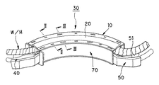
図1は本発明の第1実施形態に係るプロテクタの全体斜視図、図2は図1のII-II断面矢視図、図3は図1のIII-III断面矢視図、図4は図1に示したプロテクタの分解斜視図である。
【0019】
本第1実施形態に係るプロテクタとしてのハーネス用プロテクタ30は、図1乃至図4に示すように、蓋部20を備えて内部にワイヤハーネス(電線)W/Hを収容保持する電線収容空間を備えたプロテクタ本体10が、電気絶縁性の合成樹脂材料によって、ヒンジ用長尺部材50の長手方向形状に合わせた円弧形の長尺状に形成されている。
【0020】
前記ヒンジ用長尺部材50は、リヤハッチゲートのヒンジ機構を構成しており、長手方向に沿って側面(図中、上面)に設けられた凹溝51を有する断面コ字状の金属部材である。
前記プロテクタ本体10には、線状体であるウォッシャーホース40を保持する線状体保持部60が一体に設けられており、前記ヒンジ用長尺部材50の長手方向形状に合わせて長尺状に形成されたカバー部材70が、該プロテクタ本体10をヒンジ用長尺部材50に取り付ける為の取付手段として着脱自在に取り付けられている。
【0021】
前記蓋部20の両側縁内面には、図2乃至図4に示したように、下方に突出する複数対の可撓係止片21,21及び22,22が、長手方向に略等間隔で交互に形成されている。各可撓係止片21,22の下端には、後述する係止部11及び係止突起71に係止される係合用突起21a,22aが形成されている。
【0022】
前記蓋部20より長手方向の長さが若干短くされている前記プロテクタ本体10は、図2乃至図4に示したように、図中上方に開口を有する断面コ字状を有しており、内部の電線収容空間にワイヤーハーネスW/Hが挿通配置されるようになっている。
前記プロテクタ本体10の両側壁には、複数対の係止部11,11が前記可撓係止片22と同一ピッチで長手方向に沿って3カ所形成されており、前記可撓係止片22の先端を該係止部11の係止穴12に貫通させることによって、係合用突起22aが係止部11に係止され、蓋部20がプロテクタ本体10に着脱自在に取り付けられるようになっている(図2参照)。
【0023】
また、プロテクタ本体10の電線収容空間外である底面の両側縁には、図2乃至図4に示したように、一対の保持片61,61から成る線状体保持部60が長手方向に3カ所形成されている。各保持片61の先端内側には、一対の保持片61,61間に挟まれたウォッシャーホース40を係止する保持用係止突起61aが突設されている。
更に、前記プロテクタ本体10の底壁の長手方向の両端部には、図4に示したように、ワイヤーハーネスW/Hを粘着テープ等で巻付け固定する為の固定片13が突設されている。
【0024】
前記カバー部材70は、図2乃至図4に示したように、図中上方に開口を有する断面コ字状を有して前記ヒンジ用長尺部材50の長手方向形状に合わせた円弧形の長尺状に形成されており、底部の内面幅が前記ヒンジ用長尺部材50の幅と略同一とされている。
【0025】
前記カバー部材70の両側壁の上端部内面には、複数対の係止突起71,71が前記可撓係止片21,21と同一ピッチで長手方向に沿って4カ所形成されており、前記可撓係止片21の係合用突起21aを該係止突起71に係止させることによって、カバー部材70がプロテクタ本体10に着脱自在に取り付けられるようになっている(図3参照)。
【0026】
そこで、本第1実施形態のハーネス用プロテクタ30を用いて前記ヒンジ用長尺部材50にワイヤーハーネスW/Hを配索する際には、先ず、プロテクタ本体10の底壁に沿ってワイヤーハーネスW/Hを添わせ、粘着テープで固定片13に巻付け固定する。
そして、プロテクタ本体10の上方開口を蓋部20で覆った状態で、該蓋部20の可撓係止片22をプロテクタ本体10の係止部11に係止させ、蓋部20をプロテクタ本体10に取り付ける。
【0027】
次に、プロテクタ本体10の底面に設けた複数対の保持片61,61間にウォッシャーホース40をそれぞれ押込み、各線状体保持部60にウォッシャーホース40を保持させる。
そして、前記各線状体保持部60がウォッシャーホース40を伴って前記凹溝51内に収納されるように、プロテクタ本体10を前記ヒンジ用長尺部材50に添わせた後、前記カバー部材70がヒンジ用長尺部材50の周囲を覆うようにしてプロテクタ本体10に取り付けられる。
【0028】
この際、前記各線状体保持部60が前記凹溝51内に収納されることにより、前記プロテクタ本体10は前記ヒンジ用長尺部材50に対して位置決め固定(仮固定)されるので、該ヒンジ用長尺部材50に対するプロテクタ本体10の取付け作業性が向上する。そして、前記可撓係止片21が係止突起71に係止されることにより、カバー部材70はプロテクタ本体10に着脱自在に固定される。
【0029】
即ち、本第1実施形態のハーネス用プロテクタ30によれば、ワイヤハーネスW/Hを電線収容空間内に収容保持したプロテクタ本体10がヒンジ用長尺部材50に取付けられた際、該プロテクタ本体10の線状体保持部60に保持されたウォッシャーホース40はヒンジ用長尺部材50の凹溝51内に収容されており、該プロテクタ本体10のみが、前記ヒンジ用長尺部材50の表面に配置される。
【0030】
そこで、本第1実施形態のハーネス用プロテクタ30は、線状体保持部に保持された線状体がプロテクタ本体の外側に配索される従来のプロテクタに比べて、取付スペースを小型化することができる。
即ち、前記ハーネス用プロテクタ30によれば、リヤハッチゲートのヒンジ用長尺部材50はリヤハッチゲートを閉じた状態での車室内への突出量が小さくなり、荷物や乗員との干渉が生じ難くなる。
【0031】
また、前記線状体保持部60に保持されたウォッシャーホース40は、ヒンジ用長尺部材50の凹溝51内に収容されており、ハーネス用プロテクタ10の表面に露呈することがないので、美観が向上して車室内からの見栄えを良くすることができる。
【0032】
更に、本第1実施形態のハーネス用プロテクタ30によれば、取付手段としてのカバー部材70がヒンジ用長尺部材50の周囲を覆うようにしてプロテクタ本体10に取り付けられて一体とされることによって、該プロテクタ本体10をヒンジ用長尺部材50に沿って固定できる。
そこで、前記ハーネス用プロテクタ30の取付け強度は、プロテクタ本体10とカバー部材70との固着力によって決まるので、ヒンジ用長尺部材50の構造に係わらずハーネス用プロテクタ30の取付け強度を高めることが容易である。
【0033】
また、電気絶縁性の合成樹脂材料等によって成形されるプロテクタ本体10とカバー部材70とは、上述した可撓係止片21や係止突起71の如き簡単な構造の係止手段によって着脱自在とすることができるので、従来のプロテクタのアンカー部に比べて取付け時の位置合わせが容易となり、前記アンカー部のように取外し時に破損し易くなることはない。そこで、前記ハーネス用プロテクタ30は、ヒンジ用長尺部材50に対する着脱性が向上する。
【0034】
また、上記ハーネス用プロテクタ30における線状体保持部60は、ワイヤハーネスW/Hを収容保持する前記プロテクタ本体10の電線収容空間外に設けられている。
そこで、前記ウォッシャーホース40は、上述した如くヒンジ用長尺部材50に対してワイヤハーネスW/Hと伴にプロテクタ本体10に組み付けられる一体組付けに限らず、後工程において前記ヒンジ用長尺部材50に対して単独でプロテクタ本体10に組み付けられる後組付けにも対応可能であり、組付け作業におけるウォッシャーホース40の組付け自由度が向上する。
【0035】
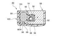
図5は参考例のプロテクタの全体斜視図、図6は図5のVI-VI断面矢視図、図7は図5のVII-VII断面矢視図、図8は図5のVIII-VIII断面矢視図、図9は図5のIX-IX断面矢視図、図10は図5に示したプロテクタの分解斜視図である。
【0036】
参考例のプロテクタであるハーネス用プロテクタ80は、図5乃至図10に示すように、内部にワイヤハーネス(電線)W/Hを収容保持する電線収容空間を備えたプロテクタ本体90が、電気絶縁性の合成樹脂材料によって、上記ヒンジ用長尺部材55の長手方向形状に合わせた円弧形の長尺状に形成されている。前記ヒンジ用長尺部材55は、リヤハッチゲートのヒンジ機構を構成しており、長手方向に沿って側面に設けられた凹溝56を有する断面コ字状の金属部材である。前記凹溝56の底部には、段付き係止穴57が穿設されている。
【0037】
前記ヒンジ用長尺部材55及び前記プロテクタ本体90の双方を抱持するようにこれらヒンジ用長尺部材55及びプロテクタ本体90の長手方向形状に合わせて長尺状に形成されたカバー部材100が、これらヒンジ用長尺部材55及びプロテクタ本体90に取付手段として着脱自在に取り付けられている。
【0038】
前記プロテクタ本体90は、図6乃至図9に示したように、図中下方に開口を有する断面コ字状を有しており、内部の電線収容空間にワイヤーハーネスW/Hが挿通配置されるようになっている。
前記プロテクタ本体90の両側壁の下端部内面には、複数対の可撓係止片95,95が長手方向に沿って2カ所突設されており、対向するこれら可撓係止片95,95の先端間に構成されるスリットより前記ワイヤーハーネスW/Hを押し込むことによって、該ワイヤーハーネスW/Hが電線収容空間内に収容保持される(図7,8参照)。
【0039】
また、プロテクタ本体90の電線収容空間外である一側面(図中、右側面)には、図10に示したように、線状体であるウォッシャーホース40を保持する線状体保持部91,93が長手方向に2カ所形成されている。
前記線状体保持部91は、図6及び図7に示したように、図中下方に開口する断面L字状の保持片92から成り、互いに対向する保持片92の先端内側とプロテクタ本体90の側面とには、これらの間に挟まれたウォッシャーホース40を係止する保持用係止突起96が突設されている。
【0040】
更に、前記保持片92の外側面には、図6に示したように、前記凹溝56の底部に穿設された段付き係止穴57に挿通される略円柱状の係合突起98が突設されている。該係合突起98の先割れ状の先端外面には、段付き係止穴57における大径部57aの段部に係止される小突起98aが突設されている。
【0041】
前記線状体保持部93は、図8及び図9に示したように、図中上方に開口する断面L字状の保持片94から成り、互いに対向する保持片94の先端内側とプロテクタ本体90の側面とには、これらの間に挟まれたウォッシャーホース40を係止する保持用係止突起97が突設されている。
前記プロテクタ本体90の底壁の長手方向の一端部には、図10に示したように、ワイヤーハーネスW/Hを粘着テープ等で巻付け固定する為の固定片99が突設されている。
【0042】
前記カバー部材100は、図6乃至図10に示したように、上方に開口を有する断面コ字状を有して前記ヒンジ用長尺部材55及びプロテクタ本体90の長手方向形状に合わせた円弧形の長尺状に形成されており、これらヒンジ用長尺部材55及びプロテクタ本体100の双方を抱持するように底部の内面幅が前記ヒンジ用長尺部材55の幅と前記プロテクタ本体90の幅とを加えた幅と略同一とされている。
【0043】
前記カバー部材100の一方の側壁上端部には、係止突起101や係止バンド103が形成されており、他方の側壁内面には、係合突起102が形成されている。
そして、図7に示したように前記係止突起101を前記プロテクタ本体90の上縁に係止させると共に、図6に示したように前記係合突起102を前記ヒンジ用長尺部材55に穿設した段付き係止穴57の大径部57aに係止させることによって、カバー部材100がこれらプロテクタ本体90及びヒンジ用長尺部材55に着脱自在に取り付けられるようになっている。
【0044】
そこで、参考例のハーネス用プロテクタ80を用いて前記ヒンジ用長尺部材55にワイヤーハーネスW/Hを配索する際には、先ず、前記可撓係止片95,95の先端間に構成されるスリットより前記ワイヤーハーネスW/Hを押し込むことによって、プロテクタ本体90の底壁に沿って該ワイヤーハーネスW/Hを添わせ、粘着テープで固定片99に巻付け固定する。
【0045】
次に、プロテクタ本体90の一側面に設けた線状体保持部91,93に、それぞれ下方開口又は上方開口からウォッシャーホース40をそれぞれ押込み、各線状体保持部91,93にウォッシャーホース40を保持させる。
そして、前記各線状体保持部91,93がウォッシャーホース40を伴って前記凹溝56内に収納されるように、プロテクタ本体90を前記ヒンジ用長尺部材55に添わせた後、前記カバー部材100がヒンジ用長尺部材55及びプロテクタ本体90の双方を抱持するようにしてこれらヒンジ用長尺部材55及びプロテクタ本体90に取り付けられる。
【0046】
この際、前記各線状体保持部91,93が前記凹溝56内に収納されると共に前記係合突起98が前記段付き係止穴57に挿通されて係止されることにより、前記プロテクタ本体90は前記ヒンジ用長尺部材55に対して位置決め固定(仮固定)されるので、該ヒンジ用長尺部材55に対するプロテクタ本体90の取付け作業性が向上する。
そして、前記係止突起101が前記プロテクタ本体90の上縁に係止され、前記係合突起102が前記ヒンジ用長尺部材55の大径部57aに係止されると共に、前記係止バンド103を緊締することにより、カバー部材100はヒンジ用長尺部材55及びプロテクタ本体90の双方を抱持するように着脱自在に固定される。
【0047】
即ち、参考例のハーネス用プロテクタ80によれば、ワイヤハーネスW/Hを電線収容空間内に収容保持したプロテクタ本体90がヒンジ用長尺部材55に取付けられた際、該プロテクタ本体90の線状体保持部91,93に保持されたウォッシャーホース40はヒンジ用長尺部材55の凹溝56内に収容されており、該プロテクタ本体90のみが、前記ヒンジ用長尺部材55の表面に配置される。
【0048】
そこで、参考例のハーネス用プロテクタ80は、線状体保持部に保持された線状体がプロテクタ本体の外側に配索される従来のプロテクタに比べて、取付スペースを小型化することができる。即ち、前記ハーネス用プロテクタ80によれば、リヤハッチゲートのヒンジ用長尺部材55はリヤハッチゲートを閉じた状態での車室内への突出量が小さくなり、荷物や乗員との干渉が生じ難くなる。
【0049】
また、前記線状体保持部91,93に保持されたウォッシャーホース40は、ヒンジ用長尺部材55の凹溝56内に収容されており、ハーネス用プロテクタ80の表面に露呈することがないので、美観が向上して車室内からの見栄えを良くすることができる。
【0050】
更に、参考例のハーネス用プロテクタ80によれば、取付手段としてのカバー部材100がヒンジ用長尺部材55及びプロテクタ本体90の双方を抱持するようにしてこれらヒンジ用長尺部材55及びプロテクタ本体90に取り付けられて一体とされることによって、該プロテクタ本体90をヒンジ用長尺部材55に沿って固定できる。そこで、ヒンジ用長尺部材55及びプロテクタ本体90の双方が、カバー部材100により覆われており、美観が向上して車室内からの見栄えを更に良くすることができる。
【0051】
また、上記ハーネス用プロテクタ80における線状体保持部91,93は、ワイヤハーネスW/Hを収容保持する前記プロテクタ本体90の電線収容空間外に設けられている。
そこで、前記ウォッシャーホース40は、上述した如くヒンジ用長尺部材55に対してワイヤハーネスW/Hと伴にプロテクタ本体90に組み付けられる一体組付けに限らず、後工程において前記ヒンジ用長尺部材55に対して単独でプロテクタ本体90に組み付けられる後組付けにも対応可能であり、組付け作業におけるウォッシャーホース40の組付け自由度が向上する。
【0052】
更に、図5に示したように、ヒンジ用ダンパー110が、前記ヒンジ用長尺部材55における前記凹溝56が設けられた側面とは反対の側面に取付けられている。
そこで、前記ヒンジ用長尺部材55の凹溝56に沿って配索され、更に車体側に配索されるワイヤハーネスW/H及びウォッシャーホース40は、ヒンジ用ダンパー110と干渉する虞はない。
従って、これらワイヤハーネスW/H及びウォッシャーホース40を車体側に引き回す為の配索スペースが、ヒンジ用ダンパー110との干渉によって制限を受けることがなく、配索自由度及び配索作業性が向上する。
【0053】
尚、本発明のプロテクタの取付構造におけるプロテクタ本体、カバー部材、ヒンジ用長尺部材、及び線状体等の構成は、上記各実施形態の構成に限定されるものではなく、本発明の趣旨に基づいて種々の形態を採りうることは言うまでもない。
例えば、上記各実施形態においては、線状体としてウォッシャーホース40を線状体保持部60(91,93)に保持した場合について説明したが、リヤドアオープナケーブル等の他の線状体を保持することができることは言うまでもない。
【0054】
又、プロテクタ本体やカバー部材等の形状は、ヒンジ用長尺部材の形状に合わせて種々の形状を採りうることは勿論であり、線状体保持部の形状も、線状体の形状に合わせて種々の形状を採りうる。
更に、上記各実施形態では、取付手段としてカバー部材70,100を例に示したが、これに代えて、プロテクタ本体にリップ部や係止片を設け、ヒンジ用長尺部材に直接取り付けるようにしてもよい。
【0055】
【発明の効果】
上述したような本発明のプロテクタの取付構造によれば、電線を収容保持したプロテクタ本体がヒンジ用長尺部材に取付けられた際、該プロテクタ本体の線状体保持部に保持された線状体はヒンジ用長尺部材の凹溝内に収容されており、該プロテクタ本体のみが、前記ヒンジ用長尺部材の表面に配置される。また、本発明のプロテクタの取付構造によれば、複数対の係止部が設けられているので、プロテクタの取付け時の位置合わせが容易となり、また、ヒンジ用長尺部材に対する着脱性が向上する。
【0056】
そこで、線状体保持部に保持された線状体がプロテクタ本体の外側に配索される従来のプロテクタに比べて、取付スペースを小型化することができる。
また、線状体保持部に保持された線状体は、ヒンジ用長尺部材の凹溝内に収容されており、プロテクタの表面に露呈することがないので、美観が向上して車室内からの見栄えを良くすることができる。
従って、ヒンジ用長尺部材への取付スペースを小型化すると共に、美観に優れたプロテクタの取付構造を提供できる。
【図面の簡単な説明】
【図1】 本発明の第1実施形態に係るプロテクタの全体斜視図である。
【図2】 図1のII-II断面矢視図である。
【図3】 図1のIII-III断面矢視図である。
【図4】 図1に示したプロテクタの分解斜視図である。
【図5】 参考例のプロテクタの全体斜視図である。
【図6】 図5のVI-VI断面矢視図である。
【図7】 図5のVII-VII断面矢視図である。
【図8】 図5のVIII-VIII断面矢視図である。
【図9】 図5のIX-IX断面矢視図である。
【図10】 図5に示したプロテクタの分解斜視図である。[0001]
BACKGROUND OF THE INVENTION
The present invention relates to a protector mounting structure, and more particularly to a protector mounting structure that holds a linear body such as a washer hose or an opener cable in addition to an electric wire and is mounted along a long hinge member such as a trunk hinge.
[0002]
[Prior art]
Conventionally, as a protector that accommodates and holds an electric wire such as a wire harness, for example, as described in Japanese Patent Application Laid-Open No. 2000-13949, a protector body that accommodates and holds a wire harness (electric wire) is provided on the outer wall of a vehicle body. There is a harness protector (protector) provided with a plurality of linear body locking portions for inserting and locking linear bodies such as window washer hoses and rear door opener cables.
Such a protector for a harness has a predetermined covering by locking an anchor portion formed integrally with the protector body in a locking hole of a mounting surface (vehicle body panel surface) or screwing the bracket portion. It is fixed at the mounting position.
[0003]
By the way, when an electric device such as a lamp is provided on the trunk lid or rear hatch gate of the vehicle, the harness protector is provided along the long hinge member constituting the hinge mechanism such as the trunk lid or the rear hatch gate. Installed.
The wire harness is housed and held in the protector main body formed in accordance with the shape of the long hinge member, and the window washer hose or the rear door opener cable is attached to the linear body engaging portion provided on the outer wall of the protector main body. Insert and lock the linear body.
[0004]
[Problems to be solved by the invention]
However, when the harness protector as described above is attached along the long member for the hinge, the protector body that accommodates and holds the wire harness is disposed on the surface of the long member for the hinge, and the linear body is locked. The linear body locked to the part is in a state of being wired further outside the protector body.
[0005]
Therefore, the harness protector for routing the wire harness and the linear body along the long member for hinges has a problem that the accommodation space is not efficient and the size is increased. In particular, long hinge members for trunk lids and rear hatch gates are exposed in the trunk and passenger compartment with the trunk lid and rear hatch gate closed, so if the mounting space for the harness protector increases, Since the amount of protrusion into the room increases, there is a possibility that interference with luggage or passengers may occur, which is not preferable.
[0006]
In addition, linear bodies such as window washer hoses and rear door opener cables locked to the linear body locking portions provided on the outer wall of the protector body are exposed on the surface of the harness protector, which is not aesthetically pleasing. Easily affected by external force. In particular, the long member for hinges of the rear hatch gate is exposed to the passenger compartment even when the rear hatch gate is closed, and is a part that is always seen by the occupant. Not good.
[0007]
Accordingly, an object of the present invention is to solve the above-described problems, and to provide a protector mounting structure that is excellent in aesthetics while reducing the mounting space to the hinge long member.
[0008]
[Means for Solving the Problems]
The object of the present invention includes a protector main body that accommodates and holds an electric wire therein, a lid portion, a cover member, and a long hinge member, and the protector main body has the shape of the long hinge member. It is formed in a long shape togetherThe lid portion is formed in a shape that covers the upper opening of the protector body, and the cover member has a long shape that matches the shape of the long member for hinges so as to cover the periphery of the long member for hinges. Formed intoThe protector mounting structure includes: a linear body holding portion provided integrally with the protector body to hold the linear body; and a linear shape provided along the longitudinal direction of the long member for the hinge A concave groove for housing the body, a plurality of pairs of first flexible locking pieces and second flexible locking pieces projecting downward formed on inner surfaces of both side edges of the lid, and both sides of the cover member A plurality of pairs of locking projections formed on the inner surface of the upper end of the wall and a plurality of pairs of locking portions formed on both side walls of the protector body are provided, and the first flexible locking piece is This is achieved by a protector mounting structure in which the second flexible locking piece is locked to the locking portion while being locked to the locking protrusion.
[0009]
According to the above configuration, when the protector main body that accommodates and holds the electric wire is attached to the long member for hinges, the linear body held by the linear body holding portion of the protector main body is a groove in the long member for hinges. Only the protector main body is accommodated in the surface of the long member for hinges.Moreover, according to the said structure, since several pairs of latching | locking parts are provided, the position alignment at the time of attachment of a protector becomes easy, and the attachment or detachment with respect to the elongate member for hinges improves.
[0010]
Then, compared with the conventional protector in which the linear body hold | maintained at the linear body holding | maintenance part is wired outside the protector main body, a mounting space can be reduced in size.
Moreover, since the linear body hold | maintained at the linear body holding | maintenance part is accommodated in the ditch | groove of the elongate member for hinges, and it does not expose to the surface of a protector, aesthetics improve and it is from a vehicle interior. Can improve the appearance.
[0011]
In addition, Preferably, the said linear body holding | maintenance part is provided outside the electric wire accommodation space of the said protector main body which accommodates and hold | maintains an electric wire.
In this case, the linear body is integrally assembled to the protector main body together with the electric wire with respect to the long hinge member, or is assembled to the protector main body independently with respect to the long hinge member. Both can be accommodated, and the degree of freedom of assembly of the linear body in the assembly work is improved.
[0012]
Preferably, the protector main body is positioned and fixed with respect to the long member for hinge by a linear body holding portion accommodated in the concave groove.
In this case, the workability of attaching the protector body to the long hinge member is improved.
[0014]
Therefore, since the attachment strength of the protector is determined by the fixing force between the protector main body and the cover member, it is easy to increase the attachment strength of the protector regardless of the structure of the long hinge member.
In addition, the protector body and cover member, which are molded from an electrically insulating synthetic resin material, can be detachable by a simple locking means. Detachability is improved without the locking means being easily damaged.
[0016]
Preferably, the hinge damper is attached to a side surface of the long hinge member opposite to the side surface provided with the concave groove.
In this case, the wiring space of the electric wire and the linear body is not limited by interference with the hinge damper.
[0017]
Also preferablyThe lid is detachably attached to the protector body so as to cover the protector body and the electric wire.
[0018]
DETAILED DESCRIPTION OF THE INVENTION
Hereinafter, a protector mounting structure according to an embodiment of the present invention will be described in detail with reference to the accompanying drawings.
1 is an overall perspective view of the protector according to the first embodiment of the present invention, FIG. 2 is a sectional view taken along the line II-II in FIG. 1, FIG. 3 is a sectional view taken along the line III-III in FIG. It is a disassembled perspective view of the protector shown in FIG.
[0019]
As shown in FIGS. 1 to 4, the
[0020]
The
The
[0021]
As shown in FIGS. 2 to 4, a plurality of pairs of
[0022]
The
On both side walls of the
[0023]
Further, on both side edges of the bottom surface of the
Further, as shown in FIG. 4, fixing
[0024]
As shown in FIGS. 2 to 4, the
[0025]
A plurality of pairs of locking
[0026]
Therefore, when wiring the wire harness W / H to the
Then, with the upper opening of the
[0027]
Next, the
Then, after the
[0028]
At this time, the
[0029]
That is, according to the
[0030]
Therefore, the
That is, according to the
[0031]
Further, the
[0032]
Further, according to the
Therefore, since the attachment strength of the
[0033]
Further, the
[0034]
Moreover, the linear body holding |
Therefore, the
[0035]
FIG.Reference example6 is a sectional view taken along the line VI-VI in FIG. 5, FIG. 7 is a sectional view taken along the line VII-VII in FIG. 5, FIG. 8 is a sectional view taken along the line VIII-VIII in FIG. FIG. 10 is a sectional view taken along the line IX-IX in FIG. 5, and FIG. 10 is an exploded perspective view of the protector shown in FIG.
[0036]
Reference exampleProtectorIsAs shown in FIGS. 5 to 10, the
[0037]
A
[0038]
As shown in FIGS. 6 to 9, the protector
A plurality of pairs of
[0039]
Further, on one side surface (right side surface in the figure) of the protector
As shown in FIGS. 6 and 7, the linear
[0040]
Further, on the outer surface of the holding
[0041]
As shown in FIGS. 8 and 9, the linear
As shown in FIG. 10, a fixing
[0042]
As shown in FIGS. 6 to 10, the
[0043]
A locking
Then, as shown in FIG. 7, the locking
[0044]
there,Reference exampleWhen the wire harness W / H is routed to the
[0045]
Next, the
Then, after the
[0046]
At this time, each of the linear
The locking
[0047]
That is,Reference exampleAccording to the protector for
[0048]
there,Reference
[0049]
Further, the
[0050]
Furthermore,Reference exampleAccording to the
[0051]
Moreover, the linear body holding |
Therefore, the
[0052]
Further, as shown in FIG. 5, the
Therefore, the wire harness W / H and the
Accordingly, the wiring space for routing the wire harness W / H and the
[0053]
Note that the configurations of the protector body, the cover member, the long hinge member, the linear body, and the like in the protector mounting structure of the present invention are not limited to the configurations of the above-described embodiments, and are within the spirit of the present invention. It goes without saying that various forms can be taken.
For example, in each of the above embodiments, the case where the
[0054]
In addition, the shape of the protector body, cover member, etc. can take various shapes according to the shape of the long hinge member, and the shape of the linear body holding portion also matches the shape of the linear body. Various shapes can be adopted.
Further, in each of the above embodiments, the
[0055]
【The invention's effect】
According to the protector mounting structure of the present invention as described above, when the protector main body that accommodates and holds the electric wire is attached to the long member for hinges, the linear body that is held by the linear body holding portion of the protector main body. Is accommodated in the groove of the long member for hinges, and only the protector main body is disposed on the surface of the long member for hinges.In addition, according to the protector mounting structure of the present invention, since a plurality of pairs of locking portions are provided, positioning at the time of mounting the protector is facilitated, and detachability with respect to the long hinge member is improved. .
[0056]
Then, compared with the conventional protector in which the linear body hold | maintained at the linear body holding | maintenance part is wired outside the protector main body, a mounting space can be reduced in size.
Moreover, since the linear body hold | maintained at the linear body holding | maintenance part is accommodated in the ditch | groove of the elongate member for hinges, and it does not expose to the surface of a protector, aesthetics improve and it is from a vehicle interior. Can improve the appearance.
Accordingly, it is possible to provide a protector mounting structure that is excellent in aesthetics while reducing the mounting space on the long hinge member.
[Brief description of the drawings]
FIG. 1 is an overall perspective view of a protector according to a first embodiment of the present invention.
2 is a cross-sectional view taken along the line II-II in FIG.
3 is a cross-sectional view taken along the line III-III in FIG.
4 is an exploded perspective view of the protector shown in FIG. 1. FIG.
[Figure 5]Reference exampleIt is a whole perspective view of a protector.
6 is a cross-sectional view taken along the line VI-VI in FIG. 5;
7 is a sectional view taken along the line VII-VII in FIG.
8 is a cross-sectional view taken along the line VIII-VIII in FIG.
9 is a cross-sectional view taken along the line IX-IX in FIG.
FIG. 10 is an exploded perspective view of the protector shown in FIG.
Claims (5)
線状体を保持するべく前記プロテクタ本体に一体に設けられた線状体保持部と、
前記ヒンジ用長尺部材の長手方向に沿って設けられた線状体を収納する凹溝と、
前記蓋部の両側縁内面に形成された下方に突出する複数対の第1の可撓係止片及び第2の可撓係止片と、
前記カバー部材の両側壁の上端部内面に形成された複数対の係止突起と、
前記プロテクタ本体の両側壁に形成された複数対の係止部と、
を設け、
前記第1の可撓係止片を前記係止突起に係止させるとともに、前記第2の可撓係止片を前記係止部に係止させたこと、を特徴とするプロテクタの取付構造。A protector main body that accommodates and holds an electric wire therein, a lid, a cover member, and a long hinge member, and the protector main body is formed in a long shape in accordance with the shape of the long hinge member The lid portion is formed in a shape covering the upper opening of the protector body, and the cover member is long in accordance with the shape of the hinge long member so as to cover the periphery of the hinge long member. A protector mounting structure formed in a shape ,
A linear body holding portion provided integrally with the protector body to hold the linear body;
A concave groove for accommodating a linear body provided along the longitudinal direction of the long member for hinges;
A plurality of pairs of first flexible locking pieces and second flexible locking pieces projecting downward formed on inner surfaces of both side edges of the lid portion;
A plurality of pairs of locking projections formed on the inner surfaces of the upper end portions of both side walls of the cover member;
A plurality of pairs of locking portions formed on both side walls of the protector body;
Provided,
The protector mounting structure, wherein the first flexible locking piece is locked to the locking protrusion, and the second flexible locking piece is locked to the locking portion.
Priority Applications (4)
| Application Number | Priority Date | Filing Date | Title |
|---|---|---|---|
| JP2002138940A JP3711087B2 (en) | 2002-05-14 | 2002-05-14 | Protector mounting structure |
| DE60334955T DE60334955D1 (en) | 2002-05-14 | 2003-04-29 | Harness protection |
| EP03101191A EP1363375B1 (en) | 2002-05-14 | 2003-04-29 | Wire harness protector |
| US10/428,118 US6861589B2 (en) | 2002-05-14 | 2003-05-02 | Harness protector |
Applications Claiming Priority (1)
| Application Number | Priority Date | Filing Date | Title |
|---|---|---|---|
| JP2002138940A JP3711087B2 (en) | 2002-05-14 | 2002-05-14 | Protector mounting structure |
Related Child Applications (1)
| Application Number | Title | Priority Date | Filing Date |
|---|---|---|---|
| JP2005120161A Division JP4021906B2 (en) | 2005-04-18 | 2005-04-18 | Protector mounting structure |
Publications (2)
| Publication Number | Publication Date |
|---|---|
| JP2003333723A JP2003333723A (en) | 2003-11-21 |
| JP3711087B2 true JP3711087B2 (en) | 2005-10-26 |
Family
ID=29700255
Family Applications (1)
| Application Number | Title | Priority Date | Filing Date |
|---|---|---|---|
| JP2002138940A Expired - Fee Related JP3711087B2 (en) | 2002-05-14 | 2002-05-14 | Protector mounting structure |
Country Status (1)
| Country | Link |
|---|---|
| JP (1) | JP3711087B2 (en) |
Families Citing this family (4)
| Publication number | Priority date | Publication date | Assignee | Title |
|---|---|---|---|---|
| JP4406458B2 (en) * | 2008-01-31 | 2010-01-27 | 本田技研工業株式会社 | Hinge structure of vehicle opening / closing body |
| EP2085550B1 (en) | 2008-01-31 | 2011-10-19 | Honda Motor Co., Ltd. | Hinge structure for vehicle open/close body |
| JP6383345B2 (en) * | 2015-12-03 | 2018-08-29 | 矢崎総業株式会社 | Wire harness protector and method of manufacturing wire harness |
| JP7028663B2 (en) * | 2018-01-31 | 2022-03-02 | 矢崎総業株式会社 | Arrangement structure and wiring method for arm covers and wire harnesses |
Family Cites Families (5)
| Publication number | Priority date | Publication date | Assignee | Title |
|---|---|---|---|---|
| JPH04113979A (en) * | 1990-09-04 | 1992-04-15 | Mazda Motor Corp | Trunk lid opening/closing structure for vehicle |
| JPH07329830A (en) * | 1994-06-07 | 1995-12-19 | Honda Access:Kk | Trunk lid opening device for vehicle |
| JP2964445B2 (en) * | 1994-11-08 | 1999-10-18 | 矢崎総業株式会社 | Harness protector |
| JPH1159290A (en) * | 1997-08-08 | 1999-03-02 | Harness Sogo Gijutsu Kenkyusho:Kk | Wire-harness fitting structure |
| JP3260114B2 (en) * | 1997-10-31 | 2002-02-25 | 矢崎総業株式会社 | Striatal protector |
-
2002
- 2002-05-14 JP JP2002138940A patent/JP3711087B2/en not_active Expired - Fee Related
Also Published As
| Publication number | Publication date |
|---|---|
| JP2003333723A (en) | 2003-11-21 |
Similar Documents
| Publication | Publication Date | Title |
|---|---|---|
| EP1363375B1 (en) | Wire harness protector | |
| US5739470A (en) | Wire harness protector with cover and adjacent U-shaped grooves | |
| EP1555162A1 (en) | Structure for mounting a door wire harness | |
| KR101037309B1 (en) | Outer protective assembly of wire harness for door and arranging structure of wire harness for door | |
| JP2001171443A (en) | Wire harness distribution structure for sliding door in automobile | |
| JP2000168466A (en) | Grommet and grommet fixing structure | |
| JP4706408B2 (en) | Wire harness wiring structure | |
| JP3191914B2 (en) | Vehicle door harness assembly structure | |
| JP2019221110A (en) | Grommet | |
| JPH1016672A (en) | Assembly structure of door harness for vehicle | |
| JP3711087B2 (en) | Protector mounting structure | |
| US6245997B1 (en) | Arrangement structure of door harness for vehicle | |
| JP4021906B2 (en) | Protector mounting structure | |
| WO2012124200A1 (en) | Wire harness routing structural element | |
| JP4412150B2 (en) | Wiring harness wiring structure using grommets | |
| JP5445410B2 (en) | Wire harness routing structure | |
| JP5983532B2 (en) | Grommet for door | |
| JP2012106705A (en) | Wire harness routing structure | |
| JP2005014824A (en) | Electrical equipment unit holder | |
| JP2003333724A (en) | Protector attaching structure | |
| JP4412145B2 (en) | Wire harness wiring structure | |
| JP5920285B2 (en) | Grommet for door and wire harness with grommet | |
| JP7464084B2 (en) | Door wiring module mounting structure | |
| JP2001151043A (en) | Wiring structure to hinged double door of luggage compartment of automobile | |
| JP3574758B2 (en) | Wire harness winding device |
Legal Events
| Date | Code | Title | Description |
|---|---|---|---|
| A977 | Report on retrieval |
Free format text: JAPANESE INTERMEDIATE CODE: A971007 Effective date: 20040716 |
|
| A131 | Notification of reasons for refusal |
Free format text: JAPANESE INTERMEDIATE CODE: A131 Effective date: 20040908 |
|
| A521 | Written amendment |
Free format text: JAPANESE INTERMEDIATE CODE: A523 Effective date: 20041104 |
|
| A131 | Notification of reasons for refusal |
Free format text: JAPANESE INTERMEDIATE CODE: A131 Effective date: 20050216 |
|
| A521 | Written amendment |
Free format text: JAPANESE INTERMEDIATE CODE: A523 Effective date: 20050418 |
|
| TRDD | Decision of grant or rejection written | ||
| A01 | Written decision to grant a patent or to grant a registration (utility model) |
Free format text: JAPANESE INTERMEDIATE CODE: A01 Effective date: 20050803 |
|
| A61 | First payment of annual fees (during grant procedure) |
Free format text: JAPANESE INTERMEDIATE CODE: A61 Effective date: 20050811 |
|
| R150 | Certificate of patent or registration of utility model |
Free format text: JAPANESE INTERMEDIATE CODE: R150 |
|
| FPAY | Renewal fee payment (event date is renewal date of database) |
Free format text: PAYMENT UNTIL: 20090819 Year of fee payment: 4 |
|
| FPAY | Renewal fee payment (event date is renewal date of database) |
Free format text: PAYMENT UNTIL: 20100819 Year of fee payment: 5 |
|
| FPAY | Renewal fee payment (event date is renewal date of database) |
Free format text: PAYMENT UNTIL: 20110819 Year of fee payment: 6 |
|
| FPAY | Renewal fee payment (event date is renewal date of database) |
Free format text: PAYMENT UNTIL: 20120819 Year of fee payment: 7 |
|
| FPAY | Renewal fee payment (event date is renewal date of database) |
Free format text: PAYMENT UNTIL: 20130819 Year of fee payment: 8 |
|
| R250 | Receipt of annual fees |
Free format text: JAPANESE INTERMEDIATE CODE: R250 |
|
| R250 | Receipt of annual fees |
Free format text: JAPANESE INTERMEDIATE CODE: R250 |
|
| R250 | Receipt of annual fees |
Free format text: JAPANESE INTERMEDIATE CODE: R250 |
|
| LAPS | Cancellation because of no payment of annual fees |