JP3706552B2 - Single axis combined plant - Google Patents
Single axis combined plant Download PDFInfo
- Publication number
- JP3706552B2 JP3706552B2 JP2001207266A JP2001207266A JP3706552B2 JP 3706552 B2 JP3706552 B2 JP 3706552B2 JP 2001207266 A JP2001207266 A JP 2001207266A JP 2001207266 A JP2001207266 A JP 2001207266A JP 3706552 B2 JP3706552 B2 JP 3706552B2
- Authority
- JP
- Japan
- Prior art keywords
- steam
- control valve
- oil
- turbine
- valve
- Prior art date
- Legal status (The legal status is an assumption and is not a legal conclusion. Google has not performed a legal analysis and makes no representation as to the accuracy of the status listed.)
- Expired - Lifetime
Links
Images


Classifications
-
- F—MECHANICAL ENGINEERING; LIGHTING; HEATING; WEAPONS; BLASTING
- F02—COMBUSTION ENGINES; HOT-GAS OR COMBUSTION-PRODUCT ENGINE PLANTS
- F02C—GAS-TURBINE PLANTS; AIR INTAKES FOR JET-PROPULSION PLANTS; CONTROLLING FUEL SUPPLY IN AIR-BREATHING JET-PROPULSION PLANTS
- F02C9/00—Controlling gas-turbine plants; Controlling fuel supply in air- breathing jet-propulsion plants
- F02C9/26—Control of fuel supply
- F02C9/42—Control of fuel supply specially adapted for the control of two or more plants simultaneously
-
- F—MECHANICAL ENGINEERING; LIGHTING; HEATING; WEAPONS; BLASTING
- F01—MACHINES OR ENGINES IN GENERAL; ENGINE PLANTS IN GENERAL; STEAM ENGINES
- F01D—NON-POSITIVE DISPLACEMENT MACHINES OR ENGINES, e.g. STEAM TURBINES
- F01D21/00—Shutting-down of machines or engines, e.g. in emergency; Regulating, controlling, or safety means not otherwise provided for
- F01D21/04—Shutting-down of machines or engines, e.g. in emergency; Regulating, controlling, or safety means not otherwise provided for responsive to undesired position of rotor relative to stator or to breaking-off of a part of the rotor, e.g. indicating such position
- F01D21/06—Shutting-down
-
- F—MECHANICAL ENGINEERING; LIGHTING; HEATING; WEAPONS; BLASTING
- F01—MACHINES OR ENGINES IN GENERAL; ENGINE PLANTS IN GENERAL; STEAM ENGINES
- F01D—NON-POSITIVE DISPLACEMENT MACHINES OR ENGINES, e.g. STEAM TURBINES
- F01D21/00—Shutting-down of machines or engines, e.g. in emergency; Regulating, controlling, or safety means not otherwise provided for
- F01D21/14—Shutting-down of machines or engines, e.g. in emergency; Regulating, controlling, or safety means not otherwise provided for responsive to other specific conditions
-
- F—MECHANICAL ENGINEERING; LIGHTING; HEATING; WEAPONS; BLASTING
- F01—MACHINES OR ENGINES IN GENERAL; ENGINE PLANTS IN GENERAL; STEAM ENGINES
- F01K—STEAM ENGINE PLANTS; STEAM ACCUMULATORS; ENGINE PLANTS NOT OTHERWISE PROVIDED FOR; ENGINES USING SPECIAL WORKING FLUIDS OR CYCLES
- F01K23/00—Plants characterised by more than one engine delivering power external to the plant, the engines being driven by different fluids
- F01K23/02—Plants characterised by more than one engine delivering power external to the plant, the engines being driven by different fluids the engine cycles being thermally coupled
- F01K23/06—Plants characterised by more than one engine delivering power external to the plant, the engines being driven by different fluids the engine cycles being thermally coupled combustion heat from one cycle heating the fluid in another cycle
- F01K23/10—Plants characterised by more than one engine delivering power external to the plant, the engines being driven by different fluids the engine cycles being thermally coupled combustion heat from one cycle heating the fluid in another cycle with exhaust fluid of one cycle heating the fluid in another cycle
- F01K23/101—Regulating means specially adapted therefor
-
- F—MECHANICAL ENGINEERING; LIGHTING; HEATING; WEAPONS; BLASTING
- F02—COMBUSTION ENGINES; HOT-GAS OR COMBUSTION-PRODUCT ENGINE PLANTS
- F02C—GAS-TURBINE PLANTS; AIR INTAKES FOR JET-PROPULSION PLANTS; CONTROLLING FUEL SUPPLY IN AIR-BREATHING JET-PROPULSION PLANTS
- F02C9/00—Controlling gas-turbine plants; Controlling fuel supply in air- breathing jet-propulsion plants
- F02C9/26—Control of fuel supply
- F02C9/46—Emergency fuel control
-
- F—MECHANICAL ENGINEERING; LIGHTING; HEATING; WEAPONS; BLASTING
- F05—INDEXING SCHEMES RELATING TO ENGINES OR PUMPS IN VARIOUS SUBCLASSES OF CLASSES F01-F04
- F05D—INDEXING SCHEME FOR ASPECTS RELATING TO NON-POSITIVE-DISPLACEMENT MACHINES OR ENGINES, GAS-TURBINES OR JET-PROPULSION PLANTS
- F05D2220/00—Application
- F05D2220/70—Application in combination with
- F05D2220/72—Application in combination with a steam turbine
-
- F—MECHANICAL ENGINEERING; LIGHTING; HEATING; WEAPONS; BLASTING
- F05—INDEXING SCHEMES RELATING TO ENGINES OR PUMPS IN VARIOUS SUBCLASSES OF CLASSES F01-F04
- F05D—INDEXING SCHEME FOR ASPECTS RELATING TO NON-POSITIVE-DISPLACEMENT MACHINES OR ENGINES, GAS-TURBINES OR JET-PROPULSION PLANTS
- F05D2220/00—Application
- F05D2220/70—Application in combination with
- F05D2220/74—Application in combination with a gas turbine
-
- F—MECHANICAL ENGINEERING; LIGHTING; HEATING; WEAPONS; BLASTING
- F05—INDEXING SCHEMES RELATING TO ENGINES OR PUMPS IN VARIOUS SUBCLASSES OF CLASSES F01-F04
- F05D—INDEXING SCHEME FOR ASPECTS RELATING TO NON-POSITIVE-DISPLACEMENT MACHINES OR ENGINES, GAS-TURBINES OR JET-PROPULSION PLANTS
- F05D2270/00—Control
- F05D2270/01—Purpose of the control system
- F05D2270/13—Purpose of the control system to control two or more engines simultaneously
-
- Y—GENERAL TAGGING OF NEW TECHNOLOGICAL DEVELOPMENTS; GENERAL TAGGING OF CROSS-SECTIONAL TECHNOLOGIES SPANNING OVER SEVERAL SECTIONS OF THE IPC; TECHNICAL SUBJECTS COVERED BY FORMER USPC CROSS-REFERENCE ART COLLECTIONS [XRACs] AND DIGESTS
- Y02—TECHNOLOGIES OR APPLICATIONS FOR MITIGATION OR ADAPTATION AGAINST CLIMATE CHANGE
- Y02E—REDUCTION OF GREENHOUSE GAS [GHG] EMISSIONS, RELATED TO ENERGY GENERATION, TRANSMISSION OR DISTRIBUTION
- Y02E20/00—Combustion technologies with mitigation potential
- Y02E20/16—Combined cycle power plant [CCPP], or combined cycle gas turbine [CCGT]
Description
【0001】
【発明の属する技術分野】
本発明はガスタービンと蒸気タービンとを1本の軸で繋いだ一軸コンバインドプラントに関し、ガスタービンと蒸気タービンとの間にクラッチを介設した場合に適用して有用なものである。
【0002】
【従来の技術】
ガスタービンと蒸気タービンとを1本の軸で繋いだ一軸コンバインドプラントは、高効率で且つ有害物質(NOX等)の排出量が少なく、また、一日の消費電力量の変化に柔軟に対応可能なプラントである。
【0003】
図3は従来の一軸コンバインドプラントの構成図である。同図に示すように、ガスタービン1と蒸気タービン2は1本の軸3で繋がれており、この軸3に発電機4も繋がれている。ガスタービン1の燃料としてはガスと油の2通りがあり、ガスタービン1への燃料ガス供給ライン5には燃料ガス用制御弁6が設けられ、ガスタービン1への燃料油供給ライン7には燃料油用制御弁8が設けられている。これらの制御弁6,8は制御油圧(作動油の圧力)を調節することにより弁開度が調節されて、ガスタービン1への燃料ガスや燃料油の供給量を制御するものである。また、蒸気タービン2への蒸気供給ライン9には蒸気加減弁10が設けられており、この蒸気加減弁10も制御油圧(作動油の圧力)を調整することにより弁開度が調節されて、蒸気タービン2への蒸気の供給量を制御するものである。
【0004】
そして、この一軸コンバインドプラントには図示のような非常遮断油系統が設けられている。即ち、ガスタービン非常遮断油ラインとして、燃料ガス制御弁6を遮断するための燃料ガス制御弁用非常遮断油ライン11と、燃料油制御弁8を遮断するための燃料油制御弁用非常遮断油ライン12とを有しており、一方の燃料ガス制御弁用非常遮断油ライン11には燃料ガス制御弁用トリップ電磁弁13が設けられ、他方の燃料油制御弁用非常遮断油ライン12には燃料油制御弁用トリップ電磁弁14が設けられている。
【0005】
従って、燃料ガス制御弁用トリップ電磁弁13のみを閉じて(励磁して)燃料ガス制御弁6の非常遮断油圧力を確立することにより、燃料ガス制御弁6による燃料ガス供給量の制御を可能とし、燃料油制御弁用トリップ電磁弁14を非励磁とすれば、燃料ガスでガスタービン1を運転することができる。逆に、燃料油制御弁用トリップ電磁弁14のみを閉じて(励磁して)燃料油制御弁8の非常遮断油圧力を確立することにより、燃料油制御弁8による燃料油供給量の制御を可能とし、燃料ガス制御弁用トリップ電磁弁13は非励磁とすれば、燃料油でガスタービン1を運転することができる。
【0006】
また、蒸気タービン非常遮断油ラインとして、蒸気加減弁10を遮断するための蒸気加減弁用非常遮断油ライン15が設けられており、この蒸気加減弁用非常遮断油ライン15には蒸気加減弁用トリップ電磁弁16が設けられている。蒸気タービン2へ蒸気を供給する際には、蒸気加減弁用トリップ電磁弁16を閉じて(励磁して)蒸気加減弁10の非常遮断油圧力を確立することにより、蒸気加減弁10による蒸気供給量の制御を可能とする。
【0007】
また、蒸気加減弁用トリップ電磁弁16は、逆止弁17,18を介して、燃料ガス制御弁用非常遮断油ライン11と燃料油制御弁用非常遮断油ライン12にも接続されている。逆止弁17は図中に矢印で示すように燃料ガス制御弁用非常遮断油ライン11から蒸気加減弁用トリップ電磁弁16への非常遮断油の流れは許容し、その逆方向の流れは阻止する。逆止弁18は図中に矢印で示すように燃料油制御弁用非常遮断油ライン12から蒸気加減弁用トリップ電磁弁16への非常遮断油の流れは許容し、その逆方向の流れは阻止する。
【0008】
この非常遮断油系統の各トリップ電磁弁13,14,16は、図示しない保護インターロック回路により下記に示す要領で作動される。
【0009】
即ち、ガスタービン1を燃料ガスで運転する場合には、燃料ガス制御弁用トリップ電磁弁13のみを閉じる(励磁する)ことで燃料ガス制御弁6のみを作動可能とする。このとき、燃料油制御弁用トリップ電磁弁14は開いたまま(非励磁のまま)にし、誤って燃料油がガスタービン1に供給されないようにする。逆に、ガスタービン1を燃料油で運転する場合には、燃料油制御弁用トリップ電磁弁14のみを閉じる(励磁する)ことで燃料油制御弁8のみを作動可能とする。このとき、燃料ガス制御弁用トリップ電磁弁13は開いたまま(非励磁のまま)にし、誤って燃料ガスがガスタービン1に供給されないようにする。
【0010】
また、従来の一軸コンバインドプラントでは、ガスタービン1と蒸気タービン2は一緒に起動するため、燃料ガス制御弁用トリップ電磁弁13又は燃料油制御弁用トリップ電磁弁14を閉じて(励磁して)ガスタービン1を起動するのと同時に、蒸気加減弁用トリップ電磁弁16も閉じて(励磁して)、蒸気加減弁10も作動可能とすることにより、蒸気タービン2も起動する。
【0011】
そして、ガスタービン1を停止させるときには、励磁されていた燃料ガス制御弁用トリップ電磁弁13(又は燃料油制御弁用トリップ電磁弁14)を開き、燃料ガス制御弁用非常遮断油ライン11(又は燃料油制御弁用非常遮断油ライン12)を介して燃料ガス制御弁6(又は燃料油制御弁8)から非常遮断油を抜くことにより、制御油(作動油)を逃がして燃料ガス制御弁6(又は燃料油制御弁8)を遮断し、燃料ガス(又は燃料油)の供給を停止する。また、蒸気タービン2を停止するときには、励磁されていた蒸気加減弁用トリップ電磁弁16も開き、蒸気加減弁用非常遮断油ライン15を介して蒸気加減弁10から非常遮断油を抜くことにより、制御油(作動油)を逃がして蒸気加減弁10を遮断し、蒸気の供給を停止する。
【0012】
しかも、従来の一軸コンバインドプラントではガスタービン1は運転状態のままにして、蒸気タービン2のみを停止させることはないため、上記のように逆止弁17,18を介して蒸気加減弁用トリップ電磁弁16と燃料ガス制御弁用非常遮断油ライン11及び燃料油制御弁用非常遮断油ライン12とを接続することにより、蒸気加減弁用トリップ電磁弁16を開けば(非励磁にすれば)、蒸気加減弁10の非常遮断油だけでなく、燃料ガス制御弁6や燃料油制御弁8の非常遮断油も抜けて、燃料ガス制御弁6や燃料油制御弁8も遮断するようにしている。このことによって確実にガスタービン1と蒸気タービン2とを同時に停止することができ、例えばガスタービン1に事故が発生したときに故障で燃料ガス制御弁用トリップ電磁弁13又は燃料油制御弁用トリップ電磁弁14が開かなくてガスタービン1に燃料ガス又は燃料油を供給し続けることより事故を拡大させるような事態を防ぐことができる。
【0013】
【発明が解決しようとする課題】
上記のような一軸コンバインドプラントに対して、最近、更に建設コストの低減要求が高まってきている。従来の一軸コンバインドプラントでは下記に示す事項がコストアップの要因となっている。
【0014】
(1) 起動時にガスタービン1と蒸気タービン2とを同時に起動するため、巨大な起動トルクを発生させることが可能なサイリスター(起動装置)を必要とする。
(2) 起動時にガスタービン1とともに蒸気タービン2も回転するため、蒸気タービン2の羽根が風損によって熱膨張しないように蒸気タービン2に冷却蒸気を供給することが必要である。しかしながら、ガスタービン1による発電機出力が上昇するまでは、ガスタービン1の排気ガスで蒸気を作る排ガスボイラーにおいて蒸気タービン2に投入可能な蒸気が作れない。このため、排ガスボイラーで蒸気タービン2に投入可能な蒸気が作られるまでの間、蒸気タービンの冷却に十分な蒸気を蒸気タービン2に供給することができるだけの非常に容量の大きな補助ボイラーが必要となる。
【0015】
そこで、現在、建設コストの低減を図るため、図4に示すようにガスタービン1(発電機4)と蒸気タービン2との間にクラッチ21を介設することにより、ガスタービン1と蒸気タービン2の結合・切り離しを可能とした一軸コンバインドプラントが提案されている。このクラッチ21を適用した一軸コンバインドプラントでは、クラッチ21によりガスタービン1と蒸気タービン2とを切り離した状態で、まず、ガスタービン1と発電機4のみを起動する。ガスタービン1が定格回転数に到達すると、発電機4を併入する。発電機併入後、ガスタービン1の排ガスにより図示しない排ガスボイラーで発生する蒸気を、蒸気タービン2に供給可能になった時点で蒸気タービン2に供給して、蒸気タービン2を起動する。そして、蒸気タービン2が定格回転数に到達後、クラッチ21を嵌合させて蒸気タービン2のトルクを発電機4に伝える。
【0016】
このクラッチ21を適用した一軸コンバインドプラントによれば、まず、ガスタービン1と発電機4のみを起動するため、起動に必要なサイリスターの容量を小さくすることができる(蒸気タービン2の重量分、容量が小さくてすむ)。また、ガスタービン1と発電機4のみが運転されている期間には、蒸気タービン2は低速回転で回っており、冷却蒸気は不要となるため、補助ボイラーの容量を小さくすることもできる。
【0017】
ところが、図3に示す従来の一軸コンバインドプラントにクラッチ21を適用してサイリスターや補助ガスボイラーの容量を低減しようとした場合、次のような問題点がある。
【0018】
(1) クラッチ21を適用した一軸コンバインドプラントでは、ガスタービン1のみを運転して蒸気タービン2は停止させることができるようにする必要がある。つまり、負荷遮断時や所内単独運転時など、低負荷又は無負荷で運転する場合、排ガスボイラーにおいて蒸気タービン2へ投入可能な圧力と温度を持った蒸気を発生されることができない。この場合、従来の一軸コンバインドプラントでは補助ボイラーから蒸気タービン2に冷却蒸気を供給することによって蒸気タービン2をガスタービン1とともに回転させておくことができた。しかし、クラッチ21を適用した一軸コンバインドプラントでは上記のように蒸気タービン用冷却蒸気を発生させることができるだけの十分大きな補助ボイラーを用意しない(このことによって設備コストを抑えることが可能)ため、低負荷又は無負荷で運転する場合には蒸気タービン2のみを停止せざるを得ない。ところが、図3に示す非常遮断油系統の構成では蒸気加減弁用トリップ電磁弁16を開くと、蒸気加減弁10だけでなく、燃料ガス制御弁6及び燃料油制御弁8も遮断するため、蒸気タービン2のみを停止させることはできない。
(2) また、逆止弁17,18を設けずに燃料ガス制御弁用非常遮断油ライン11及び燃料油制御弁用非常遮断油ライン12と蒸気加減弁用非常遮断油ライン15とを分離すると、ガスタービン1に事故が発生したときに故障で燃料ガス制御弁用トリップ電磁弁13又は燃料油制御弁用トリップ電磁弁14が開かない場合、ガスタービン1を止めることができずにガスタービン1を壊すことになる。
【0019】
従って、本発明は上記の事情に鑑み、蒸気タービンのみを停止させることもでき、しかも、ガスタービン非常遮断油ラインに設けたトリップ弁(燃料ガス制御弁用トリップ電磁弁又は燃料油制御弁用トリップ電磁弁)が故障で開かない場合でも確実にガスタービンを停止させることができる構成の非常遮断油系統を備えた一軸コンバインドプラントを提供することを課題とする。
【0020】
【課題を解決するための手段】
上記課題を解決する本発明の一軸コンバインドプラントは、ガスタービンと蒸気タービンとを1本の軸で繋ぎ、且つ、ガスタービンと蒸気タービンとの間にクラッチを介設してガスタービンと蒸気タービンの結合・切り離しを可能とした一軸コンバインドプラントにおいて、
ガスタービン非常遮断油ラインと、蒸気タービン非常遮断油ラインとを有し、ガスタービン非常遮断油ラインに設けたトリップ弁を開いたときには、ガスタービン非常遮断油ラインを介して、非常遮断油が燃料供給ラインに設けた弁から抜けることにより、この燃料供給ラインに設けた弁のみが遮断してガスタービンへの燃料の供給を停止し、
蒸気タービン非常遮断油ラインに設けたトリップ弁を開いたときには、蒸気タービン非常遮断油ラインを介して、非常遮断油が蒸気供給ラインに設けた弁から抜けることにより、この蒸気供給ラインに設けた弁のみが遮断して蒸気タービンへの蒸気の供給を停止するように構成するとともに、
ガスタービン非常遮断油ラインと蒸気タービン非常遮断油ラインとに逆止弁を介してマスタートリップ弁を接続し、このマスタートリップ弁が開いたときには、ガスタービン非常遮断油ライン及び蒸気タービン非常遮断油ラインを介して、非常遮断油が燃料供給ラインに設けた弁及び蒸気供給ラインに設けた弁から抜けることにより、この燃料供給ラインに設けた弁と蒸気供給ラインに設けた弁がともに遮断してガスタービンへの燃料の供給と蒸気タービンへの蒸気の供給とを停止するように構成してなる非常遮断油系統を備えたことを特徴とする。
【0021】
【発明の実施の形態】
以下、本発明の実施の形態を図面に基づき詳細に説明する。
【0022】
図1は本発明の実施の形態に係る一軸コンバインドプラントの構成図、図2は前記一軸コンバインドプラントに備えた非常遮断油系統の各電磁弁を作動する保護インターロック回路図である。
【0023】
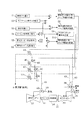
図1に示すように、ガスタービン31と蒸気タービン32は1本の軸33で繋がれており、この軸33に発電機34も繋がれている。ガスタービン31の燃料としてはガスと油の2通りがあり、ガスタービン31への燃料ガス供給ライン35には燃料ガス用制御弁36が設けられ、ガスタービン31への燃料油供給ライン37には燃料油用制御弁38が設けられている。これらの制御弁36,38は制御油圧(作動油の圧力)を調節することにより弁開度が調節されて、ガスタービン31への燃料ガスや燃料油の供給量を制御するものである。蒸気タービン32への蒸気供給ライン39には蒸気加減弁40が設けられており、この蒸気加減弁40も制御油圧(作動油の圧力)を調整することにより弁開度が調節されて、蒸気タービン32への蒸気の供給量を制御するものである。
【0024】
また、ガスタービン31(発電機34)と蒸気タービン32との間にクラッチ41を介設することでガスタービン31と蒸気タービン32の結合・切り離しを可能としており、このことによって、図示しないサイリスターや補助ボイラーの容量を小さくしている。なお、クラッチ41としては、ヘリカルスプライン嵌合構造を用いたクラッチの他、各種のクラッチを適用することができる。
【0025】
このクラッチ41を適用した一軸コンバインドプラントでは、クラッチ41によりガスタービン31と蒸気タービン32とを切り離した状態で、まず、ガスタービン31と発電機34のみを起動する。ガスタービン31が定格回転数に到達すると、発電機34を併入する。発電機併入後、ガスタービン31の排ガスにより図示しない排ガスボイラーで発生する蒸気を、蒸気タービン32に供給可能になった時点で蒸気タービン32に供給して、蒸気タービン32を起動する。そして、蒸気タービン32が定格回転数に到達後、クラッチ41を嵌合させて蒸気タービン32のトルクを発電機34に伝える。
【0026】
そして、このクラッチ41を適用した一軸コンバインドプラントには、図示のような非常遮断油系統が設けられている。即ち、ガスタービン非常遮断油ラインとして、燃料ガス制御弁36を遮断するための燃料ガス制御弁用非常遮断油ライン42と、燃料油制御弁38を遮断するための燃料油制御弁用非常遮断油ライン43とを有しており、一方の燃料ガス制御弁用非常遮断油ライン42には燃料ガス制御弁用トリップ電磁弁44が設けられ、他方の燃料油制御弁用非常遮断油ライン43には燃料油制御弁用トリップ電磁弁45が設けられている。
【0027】
従って、燃料ガス制御弁用トリップ電磁弁44のみを閉じて(励磁して)燃料ガス制御弁36の非常遮断油圧力を確立することにより、燃料ガス制御弁36による燃料ガス供給量の制御を可能とし、燃料油制御弁用トリップ電磁弁45を非励磁とすれば、燃料ガスでガスタービン31を運転することができる。逆に、燃料油制御弁用トリップ電磁弁45のみを閉じて(励磁して)燃料油制御弁38の非常遮断油圧力を確立することにより、燃料油制御弁38による燃料油供給量の制御を可能とし、燃料ガス制御弁用トリップ電磁弁44を非励磁とすれば、燃料油でガスタービン1を運転することができる。
【0028】
また、蒸気タービン非常遮断油ラインとして、蒸気加減弁40を非常遮断するための蒸気加減弁用非常遮断油ライン46が設けられており、この蒸気加減弁用非常遮断油ライン46には蒸気加減弁用トリップ電磁弁47が設けられている。蒸気タービン32へ蒸気を供給する際には、蒸気加減弁用トリップ電磁弁47を閉じて(励磁して)蒸気加減弁40の非常遮断油圧力を確立することにより、蒸気加減弁40による蒸気供給量の制御を可能とする。
【0029】
ガスタービン31を停止させるときには、励磁されていた燃料ガス制御弁用トリップ電磁弁44(又は燃料油制御弁用トリップ電磁弁45)を開き、燃料ガス制御弁用非常遮断油ライン42(又は燃料油制御弁用非常遮断油ライン43)を介して燃料ガス制御弁36(又は燃料油制御弁38)から非常遮断油を抜くことにより、制御油(作動油)を逃がして燃料ガス制御弁36(又は燃料油制御弁38)を遮断し、燃料ガス(又は燃料油)の供給を停止する。また、蒸気タービン32を停止するときには、励磁されていた蒸気加減弁用トリップ電磁弁47を開き、蒸気加減弁用非常遮断油ライン46を介して蒸気加減弁40から非常遮断油を抜くことにより、制御油(作動油)を逃がして蒸気加減弁40を遮断し、蒸気の供給を停止する。そして、従来のように蒸気加減弁用トリップ電磁弁47と燃料ガス制御弁用非常遮断油ライン42及び燃料油制御弁用非常遮断油ライン43とが逆止弁によって接続されていないため、即ち、燃料ガス制御弁用非常遮断油ライン42及び燃料油制御弁用非常遮断油ライン43と蒸気加減弁用非常遮断油ライン46とが独立しているため、蒸気加減弁用トリップ電磁弁47を開いたとき、燃料ガス制御弁36や燃料油制御弁38の非常遮断油も抜けるとはなく、蒸気タービン32のみが停止する。
【0030】
しかも、本実施の形態の一軸コンバインドプラントでは、燃料ガス制御弁用非常遮断油ライン42と、燃料油制御弁用非常遮断油ライン43と、蒸気加減弁用非常遮断油ライン46には、逆止弁48,49,50を介して、マスタートリップ電磁弁51が接続されている。逆止弁48は図中に矢印で示すように燃料ガス制御弁用非常遮断油ライン42からマスタートリップ電磁弁51への非常遮断油の流れは許容し、その逆方向の流れは阻止する。逆止弁49は図中に矢印で示すように燃料油制御弁用非常遮断油ライン43からマスタートリップ電磁弁51への非常遮断油の流れは許容し、その逆方向の流れは阻止する。逆止弁50は図中に矢印で示すように蒸気加減弁用非常遮断油ライン46からマスタートリップ電磁弁51への非常遮断油の流れは許容し、その逆方向の流れは阻止する。
【0031】
ここで、この非常遮断油系統の各トリップ電磁弁48,49,50を作動する保護インターロック回路の例を図2に基づいて説明する。
【0032】
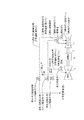
図2に示すように、ガスタービン燃料入り指令信号S2があり、且つ、タービン非常停止指令信号S4がないときに、燃料ガス選択信号S1があれば燃料ガス制御弁用トリップ電磁弁励磁信号S7が出力されて燃料ガス制御弁用トリップ電磁弁44が励磁し(閉じ)、燃料油選択信号S3があれば燃料油制御弁用トリップ電磁弁励磁信号S8が出力されて燃料油制御弁用トリップ電磁弁45が励磁する(閉じる)。また、タービン非常停止信号S4がないときには、マスタートリップ電磁弁励磁信号S9が出力されてマスタートリップ電磁弁51が励磁する(閉じる)。また、タービン非常停止信号S4がなく、且つ、蒸気タービン停止指令信号S5がないときに、蒸気タービン励磁指令信号S6があると、蒸気加減弁用トリップ電磁弁励磁信号S10が出力されて蒸気加減弁用トリップ電磁弁47が励磁する(閉じる)。
【0033】
そして、低負荷時や無負荷時などにおいて蒸気タービン32だけを停止するために蒸気タービン停止指令信号S5があったときには、蒸気加減弁用トリップ電磁弁励磁信号S10がOFFになって蒸気加減弁用トリップ電磁弁47が非励磁となり(開き)、蒸気タービン32だけが停止する。一方、タービン非常停止指令信号S4があったときは、燃料ガス制御弁用トリップ電磁弁励磁信号S7、燃料油制御弁用トリップ電磁弁励磁信号S8及び蒸気加減弁用トリップ電磁弁励磁信号S10がOFFになって燃料ガス制御弁用トリップ電磁弁44、燃料油制御弁用トリップ電磁弁45及び蒸気加減弁用トリップ電磁弁47が非励磁となるため(開くため)、ガスタービン31及び蒸気タービン32が停止し、しかも、マスタートリップ電磁弁励磁信号S9もOFFとなって、マスタートリップ電磁弁51も非励磁となるため(開くため)、蒸気タービン31及びガスタービン32が確実停止する。
【0034】
以上のことから、本実施の形態に係る一軸コンバインドプラントによれば、一軸コンバインドプラントにクラッチを適用する際の課題を解決することができる。即ち、蒸気加減弁用トリップ電磁弁47のみを開くことにより、ガスタービン31は運転状態のままにして蒸気タービン32のみを停止することができ、しかも、ガスタービン31と蒸気タービン32をともに停止する際には、マスタートリップ電磁弁51を開くとにより、ガスタービン31と蒸気タービン32とを確実に停止することができるため、例えばガスタービン31に事故が発生したときに故障で燃料ガス制御弁用トリップ電磁弁44又は燃料油制御弁用トリップ電磁弁45が開かなくても、ガスタービン31を安全に停止することができる。その結果、クラッチ41を適用して従来よりも安いコストで一軸コンバインドプラントを製作することができるようになる。
【0035】
【発明の効果】
以上、発明の実施の形態とともに具体的に説明したように、本発明の一軸コンバインドプラントは、ガスタービンと蒸気タービンとを1本の軸で繋ぎ、且つ、ガスタービンと蒸気タービンとの間にクラッチを介設してガスタービンと蒸気タービンの結合・切り離しを可能とした一軸コンバインドプラントにおいて、ガスタービン非常遮断油ラインと、蒸気タービン非常遮断油ラインとを有し、ガスタービン非常遮断油ラインに設けたトリップ弁を開いたときには、ガスタービン非常遮断油ラインを介して、非常遮断油が燃料供給ラインに設けた弁から抜けることにより、この燃料供給ラインに設けた弁のみが遮断してガスタービンへの燃料の供給を停止し、蒸気タービン非常遮断油ラインに設けたトリップ弁を開いたときには、蒸気タービン非常遮断油ラインを介して、非常遮断油が蒸気供給ラインに設けた弁から抜けることにより、この蒸気供給ラインに設けた弁のみが遮断して蒸気タービンへの蒸気の供給を停止するように構成するとともに、ガスタービン非常遮断油ラインと蒸気タービン非常遮断油ラインとに逆止弁を介してマスタートリップ弁を接続し、このマスタートリップ弁が開いたときには、ガスタービン非常遮断油ライン及び蒸気タービン非常遮断油ラインを介して、非常遮断油が燃料供給ラインに設けた弁及び蒸気供給ラインに設けた弁から抜けることにより、この燃料供給ラインに設けた弁と蒸気供給ラインに設けた弁がともに遮断してガスタービンへの燃料の供給と蒸気タービンへの蒸気の供給とを停止するように構成してなる非常遮断油系統を備えたことを特徴とする。
【0036】
従って、本発明の一軸コンバインドプラントによれば、一軸コンバインドプラントにクラッチを適用する際の課題を解決することができる。即ち、蒸気タービン非常遮断油ラインに設けたトリップ弁のみを開くことにより、ガスタービンは運転状態のままにして蒸気タービンのみを停止することができ、しかも、ガスタービンと蒸気タービンをともに停止する際には、マスタートリップ弁を開くとにより、ガスタービンと蒸気タービンとを確実に停止することができるため、例えばガスタービンに事故が発生したときに故障でガスタービン非常遮断油ラインに設けたトリップ弁が開かなくても、ガスタービンを安全に停止することができる。その結果、クラッチを適用して従来よりも安いコストで一軸コンバインドプラントを製作することができるようになる。
【図面の簡単な説明】
【図1】本発明の実施の形態に係る一軸コンバインドプラントの構成図である。
【図2】前記一軸コンバインドプラントに備えた非常遮断油系統の各電磁弁を作動する保護インターロック回路図である。
【図3】従来の一軸コンバインドプラントの構成図である。
【図4】クラッチを適用した一軸コンバインドプラントの構成図である。
【符号の説明】
31 ガスタービン
32 蒸気タービン
33 軸
34 発電機
35 燃料ガス供給ライン
36 燃料ガス制御弁
37 燃料油供給ライン
38 燃料油制御弁
39 蒸気供給ライン
40 蒸気加減弁
41 クラッチ
42 燃料ガス制御弁用非常遮断油ライン
43 燃料油制御弁用非常遮断油ライン
44 燃料ガス制御弁用トリップ電磁弁
45 燃料油制御弁用トリップ電磁弁
46 蒸気加減弁用非常遮断油ライン
47 蒸気加減弁用トリップ電磁弁
48,49,50 逆止弁
51 マスタートリップ電磁弁[0001]
BACKGROUND OF THE INVENTION
The present invention relates to a single-shaft combined plant in which a gas turbine and a steam turbine are connected by a single shaft, and is useful when applied to a case where a clutch is interposed between the gas turbine and the steam turbine.
[0002]
[Prior art]
A single-shaft combined plant that connects a gas turbine and a steam turbine with a single shaft is highly efficient, has low emissions of harmful substances (NOX, etc.), and can flexibly respond to changes in the power consumption of the day. It is a powerful plant.
[0003]
FIG. 3 is a configuration diagram of a conventional single-shaft combined plant. As shown in the figure, the gas turbine 1 and the steam turbine 2 are connected by a single shaft 3, and the generator 4 is also connected to the shaft 3. There are two types of fuel for the gas turbine 1, gas and oil. The fuel gas supply line 5 to the gas turbine 1 is provided with a fuel
[0004]
The single shaft combined plant is provided with an emergency shutoff oil system as shown in the figure. That is, as the gas turbine emergency shutoff oil line, the fuel gas control valve emergency shutoff oil line 11 for shutting off the fuel
[0005]
Therefore, the fuel gas supply amount can be controlled by the fuel
[0006]
Further, a steam control valve emergency shutoff oil line 15 for shutting off the
[0007]
The steam control valve trip solenoid valve 16 is also connected to the fuel gas control valve emergency cutoff oil line 11 and the fuel oil control valve emergency cutoff oil line 12 via check valves 17 and 18. The check valve 17 allows the flow of the emergency shutoff oil from the fuel gas control valve emergency shutoff oil line 11 to the steam control valve trip solenoid valve 16 as shown by the arrow in the figure, and blocks the flow in the reverse direction. To do. The check valve 18 permits the flow of the emergency shutoff oil from the fuel oil control valve emergency shutoff oil line 12 to the steam control valve trip solenoid valve 16 as indicated by an arrow in the figure, and blocks the flow in the reverse direction. To do.
[0008]
Each of the trip solenoid valves 13, 14, 16 of this emergency shutoff oil system is operated in the following manner by a protective interlock circuit (not shown).
[0009]
That is, when the gas turbine 1 is operated with fuel gas, only the fuel
[0010]
In the conventional single-shaft combined plant, the gas turbine 1 and the steam turbine 2 are started together, so the fuel gas control valve trip solenoid valve 13 or the fuel oil control valve trip solenoid valve 14 is closed (excited). At the same time when the gas turbine 1 is started, the steam control valve trip solenoid valve 16 is also closed (excited), and the
[0011]
When the gas turbine 1 is stopped, the excited fuel gas control valve trip solenoid valve 13 (or the fuel oil control valve trip solenoid valve 14) is opened, and the fuel gas control valve emergency shutoff oil line 11 (or By draining the emergency shutoff oil from the fuel gas control valve 6 (or the fuel oil control valve 8) via the fuel oil control valve emergency shutoff oil line 12), the control oil (operating oil) is released and the fuel
[0012]
In addition, in the conventional single-shaft combined plant, the gas turbine 1 remains in an operating state and only the steam turbine 2 is not stopped. Therefore, the trip solenoid for steam control valve via the check valves 17 and 18 as described above. By connecting the valve 16 to the emergency shutoff oil line 11 for the fuel gas control valve and the emergency shutoff oil line 12 for the fuel oil control valve to open the trip solenoid valve 16 for the steam control valve (if de-energized), Not only the emergency shutoff oil of the
[0013]
[Problems to be solved by the invention]
Recently, there has been an increasing demand for reduction in construction cost for the single-shaft combined plant as described above. In the conventional single-shaft combined plant, the following items are the cause of cost increase.
[0014]
(1) Since the gas turbine 1 and the steam turbine 2 are started simultaneously at the time of starting, a thyristor (starting device) capable of generating a huge starting torque is required.
(2) Since the steam turbine 2 rotates together with the gas turbine 1 at the time of startup, it is necessary to supply cooling steam to the steam turbine 2 so that the blades of the steam turbine 2 do not thermally expand due to windage. However, until the generator output by the gas turbine 1 increases, steam that can be input to the steam turbine 2 cannot be produced in the exhaust gas boiler that produces steam from the exhaust gas of the gas turbine 1. Therefore, there is a need for an auxiliary boiler having a very large capacity capable of supplying steam sufficient for cooling the steam turbine to the steam turbine 2 until steam that can be input to the steam turbine 2 is produced by the exhaust gas boiler. Become.
[0015]
Therefore, at present, in order to reduce the construction cost, the clutch 21 is interposed between the gas turbine 1 (generator 4) and the steam turbine 2 as shown in FIG. A single-shaft combined plant has been proposed that can be connected and disconnected. In the single-shaft combined plant to which the clutch 21 is applied, only the gas turbine 1 and the generator 4 are started up with the gas turbine 1 and the steam turbine 2 separated by the clutch 21. When the gas turbine 1 reaches the rated speed, the generator 4 is inserted. After entering the generator, the steam generated in the exhaust gas boiler (not shown) by the exhaust gas from the gas turbine 1 is supplied to the steam turbine 2 when the steam turbine 2 can be supplied, and the steam turbine 2 is started. Then, after the steam turbine 2 reaches the rated rotational speed, the clutch 21 is engaged to transmit the torque of the steam turbine 2 to the generator 4.
[0016]
According to the single-shaft combined plant to which the clutch 21 is applied, since only the gas turbine 1 and the generator 4 are started, the capacity of the thyristor necessary for starting can be reduced (the weight of the steam turbine 2, the capacity) Is small). Further, during the period in which only the gas turbine 1 and the generator 4 are operated, the steam turbine 2 rotates at a low speed and no cooling steam is required, so that the capacity of the auxiliary boiler can be reduced.
[0017]
However, when the clutch 21 is applied to the conventional single-shaft combined plant shown in FIG. 3 to reduce the capacity of the thyristor or auxiliary gas boiler, there are the following problems.
[0018]
(1) In a single-shaft combined plant to which the clutch 21 is applied, it is necessary to operate only the gas turbine 1 and to stop the steam turbine 2. That is, when operating with a low load or no load, such as when the load is interrupted or when the station is operating alone, steam having a pressure and temperature that can be charged into the steam turbine 2 cannot be generated in the exhaust gas boiler. In this case, in the conventional single-shaft combined plant, the steam turbine 2 can be rotated together with the gas turbine 1 by supplying the cooling steam from the auxiliary boiler to the steam turbine 2. However, the single-shaft combined plant to which the clutch 21 is applied does not provide a sufficiently large auxiliary boiler that can generate the cooling steam for the steam turbine as described above (this can reduce the equipment cost), so that the load is low. Or when operating with no load, only the steam turbine 2 must be stopped. However, in the configuration of the emergency shutoff oil system shown in FIG. 3, when the trip valve for steam control valve 16 is opened, not only the
(2) If the emergency cutoff oil line 11 for the fuel gas control valve, the emergency cutoff oil line 12 for the fuel oil control valve, and the emergency cutoff oil line 15 for the steam control valve are separated without providing the check valves 17 and 18. If an accident occurs in the gas turbine 1 and the fuel gas control valve trip solenoid valve 13 or the fuel oil control valve trip solenoid valve 14 does not open due to a failure, the gas turbine 1 cannot be stopped and the gas turbine 1 cannot be stopped. Will be broken.
[0019]
Therefore, in view of the above circumstances, the present invention can stop only the steam turbine, and further, a trip valve (trip solenoid valve for fuel gas control valve or trip for fuel oil control valve) provided in the gas turbine emergency shutoff oil line. It is an object of the present invention to provide a single-shaft combined plant including an emergency shutoff oil system that can reliably stop a gas turbine even when the solenoid valve is not opened due to a failure.
[0020]
[Means for Solving the Problems]
The single-shaft combined plant of the present invention that solves the above problems connects a gas turbine and a steam turbine with a single shaft, and a clutch is interposed between the gas turbine and the steam turbine to connect the gas turbine and the steam turbine. In a single-shaft combined plant that can be connected and disconnected,
When the trip valve provided in the gas turbine emergency shutoff oil line is opened, the emergency shutoff oil is fueled via the gas turbine emergency shutoff oil line. By removing from the valve provided in the supply line, only the valve provided in the fuel supply line is shut off and the supply of fuel to the gas turbine is stopped.
When the trip valve provided in the steam turbine emergency shut-off oil line is opened, the emergency shut-off oil is released from the valve provided in the steam supply line via the steam turbine emergency shut-off oil line. Is configured to shut off the supply of steam to the steam turbine,
When a master trip valve is connected to the gas turbine emergency shut-off oil line and the steam turbine emergency shut-off oil line via a check valve and the master trip valve is opened, the gas turbine emergency shut-off oil line and the steam turbine emergency shut-off oil line When the emergency shutoff oil comes out of the valve provided in the fuel supply line and the valve provided in the steam supply line, both the valve provided in the fuel supply line and the valve provided in the steam supply line are shut off and gas is discharged. An emergency shutoff oil system configured to stop the supply of fuel to the turbine and the supply of steam to the steam turbine is provided.
[0021]
DETAILED DESCRIPTION OF THE INVENTION
Hereinafter, embodiments of the present invention will be described in detail with reference to the drawings.
[0022]
FIG. 1 is a configuration diagram of a single-shaft combined plant according to an embodiment of the present invention, and FIG. 2 is a protective interlock circuit diagram for operating each electromagnetic valve of an emergency shutoff oil system provided in the single-shaft combined plant.
[0023]
As shown in FIG. 1, the
[0024]
In addition, the clutch 41 is interposed between the gas turbine 31 (the generator 34) and the
[0025]
In the single-shaft combined plant to which the clutch 41 is applied, only the
[0026]
An uniaxial combined plant to which the clutch 41 is applied is provided with an emergency cutoff oil system as shown in the figure. That is, as the gas turbine emergency shutoff oil line, the fuel gas control valve emergency
[0027]
Therefore, the fuel gas supply amount can be controlled by the fuel
[0028]
In addition, a steam control valve emergency
[0029]
When the
[0030]
Moreover, in the uniaxial combined plant of the present embodiment, the emergency
[0031]
Here, an example of a protective interlock circuit that operates each
[0032]
As shown in FIG. 2, when there is a gas turbine fuel entry command signal S2 and there is no turbine emergency stop command signal S4, if there is a fuel gas selection signal S1, a trip solenoid valve excitation signal S7 for the fuel gas control valve is generated. When the fuel oil control valve
[0033]
When there is a steam turbine stop command signal S5 for stopping only the
[0034]
From the above, according to the single-shaft combined plant according to the present embodiment, it is possible to solve the problem in applying the clutch to the single-shaft combined plant. That is, by opening only the steam control valve trip solenoid valve 47, the
[0035]
【The invention's effect】
As described above in detail with the embodiment of the invention, the single-shaft combined plant of the present invention connects the gas turbine and the steam turbine with a single shaft, and the clutch between the gas turbine and the steam turbine. In a single-shaft combined plant that enables gas turbines and steam turbines to be connected and disconnected through a gas turbine, it has a gas turbine emergency shut-off oil line and a steam turbine emergency shut-off oil line. When the trip valve is opened, the emergency shutoff oil escapes from the valve provided in the fuel supply line via the gas turbine emergency shutoff oil line, so that only the valve provided in the fuel supply line is shut off and is supplied to the gas turbine. When the trip valve provided in the steam turbine emergency shutoff oil line is opened, the steam turbine The emergency shutoff oil is removed from the valve provided in the steam supply line via the normally shutoff oil line, so that only the valve provided in the steam supply line is shut off and the supply of steam to the steam turbine is stopped. In addition, a master trip valve is connected to the gas turbine emergency shut-off oil line and the steam turbine emergency shut-off oil line via a check valve. When this master trip valve is opened, the gas turbine emergency shut-off oil line and the steam turbine emergency shut-off line When the emergency shutoff oil escapes from the valve provided in the fuel supply line and the valve provided in the steam supply line through the shutoff oil line, both the valve provided in the fuel supply line and the valve provided in the steam supply line are shut off. And an emergency shutoff oil system configured to stop the supply of fuel to the gas turbine and the supply of steam to the steam turbine. And it features.
[0036]
Therefore, according to the uniaxial combined plant of the present invention, it is possible to solve the problem in applying the clutch to the uniaxial combined plant. That is, by opening only the trip valve provided in the steam turbine emergency shutoff oil line, it is possible to stop only the steam turbine while the gas turbine remains in operation, and when both the gas turbine and the steam turbine are stopped. Since the gas turbine and the steam turbine can be stopped reliably by opening the master trip valve, for example, a trip valve provided in the gas turbine emergency shut-off oil line due to a failure when an accident occurs in the gas turbine. Even if is not opened, the gas turbine can be safely stopped. As a result, a single-shaft combined plant can be manufactured at a lower cost than before by applying a clutch.
[Brief description of the drawings]
FIG. 1 is a configuration diagram of a single-shaft combined plant according to an embodiment of the present invention.
FIG. 2 is a protective interlock circuit diagram for operating each solenoid valve of an emergency shutoff oil system provided in the single-shaft combined plant.
FIG. 3 is a configuration diagram of a conventional single-shaft combined plant.
FIG. 4 is a configuration diagram of a single-shaft combined plant to which a clutch is applied.
[Explanation of symbols]
31 Gas turbine
32 Steam turbine
33 axes
34 Generator
35 Fuel gas supply line
36 Fuel gas control valve
37 Fuel oil supply line
38 Fuel oil control valve
39 Steam supply line
40 Steam control valve
41 clutch
42 Emergency shut-off oil line for fuel gas control valve
43 Emergency shut-off oil line for fuel oil control valve
44 Trip solenoid valve for fuel gas control valve
45 Trip Solenoid Valve for Fuel Oil Control Valve
46 Emergency shutoff oil line for steam control valve
47 Trip solenoid valve for steam control valve
48, 49, 50 Check valve
51 Master trip solenoid valve
Claims (1)
ガスタービン非常遮断油ラインと、蒸気タービン非常遮断油ラインとを有し、
ガスタービン非常遮断油ラインに設けたトリップ弁を開いたときには、ガスタービン非常遮断油ラインを介して、非常遮断油が燃料供給ラインに設けた弁から抜けることにより、この燃料供給ラインに設けた弁のみが遮断してガスタービンへの燃料の供給を停止し、
蒸気タービン非常遮断油ラインに設けたトリップ弁を開いたときには、蒸気タービン非常遮断油ラインを介して、非常遮断油が蒸気供給ラインに設けた弁から抜けることにより、この蒸気供給ラインに設けた弁のみが遮断して蒸気タービンへの蒸気の供給を停止するように構成するとともに、
ガスタービン非常遮断油ラインと蒸気タービン非常遮断油ラインとに逆止弁を介してマスタートリップ弁を接続し、このマスタートリップ弁が開いたときには、ガスタービン非常遮断油ライン及び蒸気タービン非常遮断油ラインを介して、非常遮断油が燃料供給ラインに設けた弁及び蒸気供給ラインに設けた弁から抜けることにより、この燃料供給ラインに設けた弁と蒸気供給ラインに設けた弁がともに遮断してガスタービンへの燃料の供給と蒸気タービンへの蒸気の供給とを停止するように構成してなる非常遮断油系統を備えたことを特徴とする一軸コンバインドプラント。In a single-shaft combined plant in which a gas turbine and a steam turbine are connected by a single shaft, and a clutch is interposed between the gas turbine and the steam turbine so that the gas turbine and the steam turbine can be connected and disconnected.
A gas turbine emergency cutoff oil line and a steam turbine emergency cutoff oil line;
When the trip valve provided in the gas turbine emergency shut-off oil line is opened, the emergency shut-off oil is released from the valve provided in the fuel supply line via the gas turbine emergency shut-off oil line. Only shut off the fuel supply to the gas turbine,
When the trip valve provided in the steam turbine emergency shut-off oil line is opened, the emergency shut-off oil is released from the valve provided in the steam supply line via the steam turbine emergency shut-off oil line. Is configured to shut off the supply of steam to the steam turbine,
When a master trip valve is connected to the gas turbine emergency shut-off oil line and the steam turbine emergency shut-off oil line via a check valve and the master trip valve is opened, the gas turbine emergency shut-off oil line and the steam turbine emergency shut-off oil line When the emergency shutoff oil comes out of the valve provided in the fuel supply line and the valve provided in the steam supply line, both the valve provided in the fuel supply line and the valve provided in the steam supply line are shut off and gas is discharged. A single-shaft combined plant comprising an emergency shutoff oil system configured to stop fuel supply to a turbine and steam supply to a steam turbine.
Priority Applications (5)
| Application Number | Priority Date | Filing Date | Title |
|---|---|---|---|
| JP2001207266A JP3706552B2 (en) | 2001-07-09 | 2001-07-09 | Single axis combined plant |
| CA002390270A CA2390270C (en) | 2001-07-09 | 2002-06-11 | Single-shaft combined plant |
| US10/173,857 US6679046B2 (en) | 2001-07-09 | 2002-06-19 | Single-shaft combined plant |
| EP02014895A EP1275817B1 (en) | 2001-07-09 | 2002-07-05 | Single-shaft combined plant |
| DE60224329T DE60224329T2 (en) | 2001-07-09 | 2002-07-05 | Einwellenkombianlage |
Applications Claiming Priority (1)
| Application Number | Priority Date | Filing Date | Title |
|---|---|---|---|
| JP2001207266A JP3706552B2 (en) | 2001-07-09 | 2001-07-09 | Single axis combined plant |
Publications (2)
| Publication Number | Publication Date |
|---|---|
| JP2003020913A JP2003020913A (en) | 2003-01-24 |
| JP3706552B2 true JP3706552B2 (en) | 2005-10-12 |
Family
ID=19043278
Family Applications (1)
| Application Number | Title | Priority Date | Filing Date |
|---|---|---|---|
| JP2001207266A Expired - Lifetime JP3706552B2 (en) | 2001-07-09 | 2001-07-09 | Single axis combined plant |
Country Status (5)
| Country | Link |
|---|---|
| US (1) | US6679046B2 (en) |
| EP (1) | EP1275817B1 (en) |
| JP (1) | JP3706552B2 (en) |
| CA (1) | CA2390270C (en) |
| DE (1) | DE60224329T2 (en) |
Families Citing this family (17)
| Publication number | Priority date | Publication date | Assignee | Title |
|---|---|---|---|---|
| JP3692340B2 (en) * | 2002-07-30 | 2005-09-07 | 三菱重工業株式会社 | COMBINED PLANT FUEL CONTROL METHOD AND CONTROL DEVICE FOR THE SAME |
| JP3702267B2 (en) * | 2002-11-13 | 2005-10-05 | 三菱重工業株式会社 | Single-shaft combined cycle plant |
| DE10308436C5 (en) | 2003-02-27 | 2010-08-26 | Heidelberger Druckmaschinen Ag | Printing platesetter for recording artwork |
| JP3930462B2 (en) * | 2003-08-01 | 2007-06-13 | 株式会社日立製作所 | Single-shaft combined cycle power generation facility and operation method thereof |
| EP1591628A1 (en) * | 2004-04-30 | 2005-11-02 | Siemens Aktiengesellschaft | Combined power plant and cooling method therefor |
| US7386982B2 (en) * | 2004-10-26 | 2008-06-17 | General Electric Company | Method and system for detecting ignition failure in a gas turbine engine |
| US20100005775A1 (en) | 2008-05-28 | 2010-01-14 | John Kipping | Combined cycle powered railway locomotive |
| DE102008046509B4 (en) * | 2008-09-10 | 2022-02-24 | Man Energy Solutions Se | Energy recovery device for a large diesel engine |
| US20100229523A1 (en) * | 2009-03-16 | 2010-09-16 | General Electric Company | Continuous combined cycle operation power plant and method |
| US8744634B2 (en) * | 2010-11-19 | 2014-06-03 | General Electric Company | Safety instrumented system (SIS) for a turbine system |
| US9353691B2 (en) * | 2012-12-18 | 2016-05-31 | General Electric Company | Fuel routing system of a gas turbine engine and method of routing fuel |
| GB2524582B (en) * | 2014-03-28 | 2016-07-20 | Mitsubishi Hitachi Power Sys | Combined cycle gas turbine plant |
| EP3318732A1 (en) * | 2016-11-07 | 2018-05-09 | Siemens Aktiengesellschaft | Method for operating a ccgt plant |
| CN108506052B (en) * | 2018-03-26 | 2020-12-01 | 桐乡市隆源纺织有限公司 | On-line testing and isolating device for emergency trip system of steam turbine generator unit |
| CN109404065B (en) * | 2018-10-12 | 2021-12-17 | 上海华电电力发展有限公司 | Control method for preventing unit tripping caused by failure of main engine valve interruption electromagnetic valve |
| JP7247071B2 (en) * | 2019-10-01 | 2023-03-28 | 東芝エネルギーシステムズ株式会社 | PLANT CONTROL DEVICE, PLANT CONTROL METHOD, AND POWER PLANT |
| CN113638809B (en) * | 2021-07-26 | 2022-11-18 | 中国联合重型燃气轮机技术有限公司 | Emergency breaking device for heavy combustion engine |
Family Cites Families (7)
| Publication number | Priority date | Publication date | Assignee | Title |
|---|---|---|---|---|
| US4969324A (en) | 1988-07-13 | 1990-11-13 | Gas Research Institute | Control method for use with steam injected gas turbine |
| DE59009440D1 (en) * | 1990-01-31 | 1995-08-31 | Asea Brown Boveri | Procedure for starting a combination system. |
| US5301499A (en) | 1990-06-28 | 1994-04-12 | General Electric Company | Overspeed anticipation and control system for single shaft combined cycle gas and steam turbine unit |
| RU2111370C1 (en) * | 1994-05-31 | 1998-05-20 | Самарский государственный технический университет | Method of starting and gas supply of power generating gas turbine plant |
| DE4426354C2 (en) | 1994-07-25 | 2003-03-06 | Alstom | KombiAnlage |
| JP3682080B2 (en) | 1994-12-27 | 2005-08-10 | 株式会社東芝 | Gas-steam combined power generation facility |
| JPH10184317A (en) | 1996-12-26 | 1998-07-14 | Fuji Electric Co Ltd | Uniaxial combined cycle plant |
-
2001
- 2001-07-09 JP JP2001207266A patent/JP3706552B2/en not_active Expired - Lifetime
-
2002
- 2002-06-11 CA CA002390270A patent/CA2390270C/en not_active Expired - Lifetime
- 2002-06-19 US US10/173,857 patent/US6679046B2/en not_active Expired - Lifetime
- 2002-07-05 DE DE60224329T patent/DE60224329T2/en not_active Expired - Lifetime
- 2002-07-05 EP EP02014895A patent/EP1275817B1/en not_active Expired - Lifetime
Also Published As
| Publication number | Publication date |
|---|---|
| DE60224329D1 (en) | 2008-02-14 |
| JP2003020913A (en) | 2003-01-24 |
| CA2390270A1 (en) | 2003-01-09 |
| US20030014962A1 (en) | 2003-01-23 |
| US6679046B2 (en) | 2004-01-20 |
| DE60224329T2 (en) | 2008-12-11 |
| CA2390270C (en) | 2005-03-01 |
| EP1275817A1 (en) | 2003-01-15 |
| EP1275817B1 (en) | 2008-01-02 |
Similar Documents
| Publication | Publication Date | Title |
|---|---|---|
| JP3706552B2 (en) | Single axis combined plant | |
| EP0615060B1 (en) | A method of operating a power plant and a power plant | |
| US10337409B2 (en) | Method for assisting a turboshaft engine in standby of a multiple-engine helicopter, and architecture of a propulsion system of a helicopter comprising at least one turboshaft engine that can be in standby | |
| EP0236959B1 (en) | Method for starting thermal power plant | |
| EP1397810A1 (en) | A brayton cycle nuclear power plant and a method of starting the brayton cycle | |
| JP2008534851A (en) | Method for starting a turbine device comprising a connectable auxiliary group | |
| JPS6038527B2 (en) | Steam turbine control device | |
| JP4128345B2 (en) | Method and apparatus for preventing rotor overspeed | |
| WO2014091786A1 (en) | Exhaust heat recovery system and exhaust heat recovery method | |
| CN110242374B (en) | Power generation system and control method of power generation system | |
| JP6511297B2 (en) | Power generator | |
| WO2015029724A1 (en) | Electricity-generating device | |
| JP3991123B2 (en) | Power generation control method and power generation apparatus | |
| JP3165619B2 (en) | Thermal stress reduction operation method of steam turbine in single shaft combined cycle | |
| JP2003286864A (en) | Fuel gas feeding system of gas turbine and operating method for the system | |
| JPH08284615A (en) | Control method for single shaft type combined cycle generating facility and device thereof | |
| JPH11350909A (en) | Prevention method for over-speed operation of steam turbine in power plant | |
| JPS62189304A (en) | Method for controlling combined plant | |
| JPS6239653B2 (en) | ||
| JPS63297705A (en) | Starter for steam turbine | |
| JP2667699B2 (en) | Single-shaft combined plant and start-up method thereof | |
| JP3955145B2 (en) | Steam injection gas turbine power generation equipment | |
| JP4973583B2 (en) | Steam turbine equipment | |
| SU1164447A1 (en) | Device for starting and cooling steam turbine | |
| JP2774665B2 (en) | Combined cycle power plant and its overspeed prevention method and apparatus |
Legal Events
| Date | Code | Title | Description |
|---|---|---|---|
| A977 | Report on retrieval |
Free format text: JAPANESE INTERMEDIATE CODE: A971007 Effective date: 20050315 |
|
| TRDD | Decision of grant or rejection written | ||
| A01 | Written decision to grant a patent or to grant a registration (utility model) |
Free format text: JAPANESE INTERMEDIATE CODE: A01 Effective date: 20050705 |
|
| A61 | First payment of annual fees (during grant procedure) |
Free format text: JAPANESE INTERMEDIATE CODE: A61 Effective date: 20050729 |
|
| R151 | Written notification of patent or utility model registration |
Ref document number: 3706552 Country of ref document: JP Free format text: JAPANESE INTERMEDIATE CODE: R151 |
|
| FPAY | Renewal fee payment (event date is renewal date of database) |
Free format text: PAYMENT UNTIL: 20080805 Year of fee payment: 3 |
|
| FPAY | Renewal fee payment (event date is renewal date of database) |
Free format text: PAYMENT UNTIL: 20090805 Year of fee payment: 4 |
|
| FPAY | Renewal fee payment (event date is renewal date of database) |
Free format text: PAYMENT UNTIL: 20090805 Year of fee payment: 4 |
|
| FPAY | Renewal fee payment (event date is renewal date of database) |
Free format text: PAYMENT UNTIL: 20100805 Year of fee payment: 5 |
|
| FPAY | Renewal fee payment (event date is renewal date of database) |
Free format text: PAYMENT UNTIL: 20100805 Year of fee payment: 5 |
|
| FPAY | Renewal fee payment (event date is renewal date of database) |
Free format text: PAYMENT UNTIL: 20110805 Year of fee payment: 6 |
|
| FPAY | Renewal fee payment (event date is renewal date of database) |
Free format text: PAYMENT UNTIL: 20110805 Year of fee payment: 6 |
|
| FPAY | Renewal fee payment (event date is renewal date of database) |
Free format text: PAYMENT UNTIL: 20120805 Year of fee payment: 7 |
|
| FPAY | Renewal fee payment (event date is renewal date of database) |
Free format text: PAYMENT UNTIL: 20130805 Year of fee payment: 8 |
|
| S111 | Request for change of ownership or part of ownership |
Free format text: JAPANESE INTERMEDIATE CODE: R313111 |
|
| R350 | Written notification of registration of transfer |
Free format text: JAPANESE INTERMEDIATE CODE: R350 |
|
| R250 | Receipt of annual fees |
Free format text: JAPANESE INTERMEDIATE CODE: R250 |
|
| EXPY | Cancellation because of completion of term |