JP3696621B2 - Jaw-like member assembly for endoscopic inspection instruments - Google Patents
Jaw-like member assembly for endoscopic inspection instruments Download PDFInfo
- Publication number
- JP3696621B2 JP3696621B2 JP53433096A JP53433096A JP3696621B2 JP 3696621 B2 JP3696621 B2 JP 3696621B2 JP 53433096 A JP53433096 A JP 53433096A JP 53433096 A JP53433096 A JP 53433096A JP 3696621 B2 JP3696621 B2 JP 3696621B2
- Authority
- JP
- Japan
- Prior art keywords
- arm
- inspection instrument
- screw member
- actuating body
- endoscopic inspection
- Prior art date
- Legal status (The legal status is an assumption and is not a legal conclusion. Google has not performed a legal analysis and makes no representation as to the accuracy of the status listed.)
- Expired - Fee Related
Links
Images


Classifications
-
- A—HUMAN NECESSITIES
- A61—MEDICAL OR VETERINARY SCIENCE; HYGIENE
- A61B—DIAGNOSIS; SURGERY; IDENTIFICATION
- A61B10/00—Other methods or instruments for diagnosis, e.g. instruments for taking a cell sample, for biopsy, for vaccination diagnosis; Sex determination; Ovulation-period determination; Throat striking implements
- A61B10/02—Instruments for taking cell samples or for biopsy
- A61B10/06—Biopsy forceps, e.g. with cup-shaped jaws
-
- A—HUMAN NECESSITIES
- A61—MEDICAL OR VETERINARY SCIENCE; HYGIENE
- A61B—DIAGNOSIS; SURGERY; IDENTIFICATION
- A61B10/00—Other methods or instruments for diagnosis, e.g. instruments for taking a cell sample, for biopsy, for vaccination diagnosis; Sex determination; Ovulation-period determination; Throat striking implements
- A61B10/02—Instruments for taking cell samples or for biopsy
- A61B10/0233—Pointed or sharp biopsy instruments
- A61B10/0266—Pointed or sharp biopsy instruments means for severing sample
-
- A—HUMAN NECESSITIES
- A61—MEDICAL OR VETERINARY SCIENCE; HYGIENE
- A61B—DIAGNOSIS; SURGERY; IDENTIFICATION
- A61B10/00—Other methods or instruments for diagnosis, e.g. instruments for taking a cell sample, for biopsy, for vaccination diagnosis; Sex determination; Ovulation-period determination; Throat striking implements
- A61B10/02—Instruments for taking cell samples or for biopsy
-
- A—HUMAN NECESSITIES
- A61—MEDICAL OR VETERINARY SCIENCE; HYGIENE
- A61B—DIAGNOSIS; SURGERY; IDENTIFICATION
- A61B17/00—Surgical instruments, devices or methods, e.g. tourniquets
- A61B17/30—Surgical pincettes without pivotal connections
-
- A—HUMAN NECESSITIES
- A61—MEDICAL OR VETERINARY SCIENCE; HYGIENE
- A61B—DIAGNOSIS; SURGERY; IDENTIFICATION
- A61B18/00—Surgical instruments, devices or methods for transferring non-mechanical forms of energy to or from the body
- A61B18/04—Surgical instruments, devices or methods for transferring non-mechanical forms of energy to or from the body by heating
- A61B18/12—Surgical instruments, devices or methods for transferring non-mechanical forms of energy to or from the body by heating by passing a current through the tissue to be heated, e.g. high-frequency current
- A61B18/14—Probes or electrodes therefor
-
- A—HUMAN NECESSITIES
- A61—MEDICAL OR VETERINARY SCIENCE; HYGIENE
- A61B—DIAGNOSIS; SURGERY; IDENTIFICATION
- A61B10/00—Other methods or instruments for diagnosis, e.g. instruments for taking a cell sample, for biopsy, for vaccination diagnosis; Sex determination; Ovulation-period determination; Throat striking implements
- A61B10/02—Instruments for taking cell samples or for biopsy
- A61B2010/0225—Instruments for taking cell samples or for biopsy for taking multiple samples
-
- A—HUMAN NECESSITIES
- A61—MEDICAL OR VETERINARY SCIENCE; HYGIENE
- A61B—DIAGNOSIS; SURGERY; IDENTIFICATION
- A61B17/00—Surgical instruments, devices or methods, e.g. tourniquets
- A61B2017/00367—Details of actuation of instruments, e.g. relations between pushing buttons, or the like, and activation of the tool, working tip, or the like
- A61B2017/00398—Details of actuation of instruments, e.g. relations between pushing buttons, or the like, and activation of the tool, working tip, or the like using powered actuators, e.g. stepper motors, solenoids
-
- A—HUMAN NECESSITIES
- A61—MEDICAL OR VETERINARY SCIENCE; HYGIENE
- A61B—DIAGNOSIS; SURGERY; IDENTIFICATION
- A61B17/00—Surgical instruments, devices or methods, e.g. tourniquets
- A61B2017/00831—Material properties
- A61B2017/00867—Material properties shape memory effect
-
- A—HUMAN NECESSITIES
- A61—MEDICAL OR VETERINARY SCIENCE; HYGIENE
- A61B—DIAGNOSIS; SURGERY; IDENTIFICATION
- A61B17/00—Surgical instruments, devices or methods, e.g. tourniquets
- A61B17/28—Surgical forceps
- A61B17/29—Forceps for use in minimally invasive surgery
- A61B2017/2901—Details of shaft
- A61B2017/2905—Details of shaft flexible
-
- A—HUMAN NECESSITIES
- A61—MEDICAL OR VETERINARY SCIENCE; HYGIENE
- A61B—DIAGNOSIS; SURGERY; IDENTIFICATION
- A61B17/00—Surgical instruments, devices or methods, e.g. tourniquets
- A61B17/28—Surgical forceps
- A61B17/29—Forceps for use in minimally invasive surgery
- A61B17/2909—Handles
- A61B2017/2912—Handles transmission of forces to actuating rod or piston
- A61B2017/2919—Handles transmission of forces to actuating rod or piston details of linkages or pivot points
- A61B2017/292—Handles transmission of forces to actuating rod or piston details of linkages or pivot points connection of actuating rod to handle, e.g. ball end in recess
-
- A—HUMAN NECESSITIES
- A61—MEDICAL OR VETERINARY SCIENCE; HYGIENE
- A61B—DIAGNOSIS; SURGERY; IDENTIFICATION
- A61B17/00—Surgical instruments, devices or methods, e.g. tourniquets
- A61B17/28—Surgical forceps
- A61B17/29—Forceps for use in minimally invasive surgery
- A61B2017/2926—Details of heads or jaws
- A61B2017/2931—Details of heads or jaws with releasable head
-
- A—HUMAN NECESSITIES
- A61—MEDICAL OR VETERINARY SCIENCE; HYGIENE
- A61B—DIAGNOSIS; SURGERY; IDENTIFICATION
- A61B17/00—Surgical instruments, devices or methods, e.g. tourniquets
- A61B17/28—Surgical forceps
- A61B17/29—Forceps for use in minimally invasive surgery
- A61B2017/2926—Details of heads or jaws
- A61B2017/2932—Transmission of forces to jaw members
- A61B2017/2933—Transmission of forces to jaw members camming or guiding means
- A61B2017/2937—Transmission of forces to jaw members camming or guiding means with flexible part
-
- A—HUMAN NECESSITIES
- A61—MEDICAL OR VETERINARY SCIENCE; HYGIENE
- A61B—DIAGNOSIS; SURGERY; IDENTIFICATION
- A61B17/00—Surgical instruments, devices or methods, e.g. tourniquets
- A61B17/28—Surgical forceps
- A61B17/29—Forceps for use in minimally invasive surgery
- A61B2017/2926—Details of heads or jaws
- A61B2017/2932—Transmission of forces to jaw members
- A61B2017/2939—Details of linkages or pivot points
- A61B2017/294—Connection of actuating rod to jaw, e.g. releasable
-
- A—HUMAN NECESSITIES
- A61—MEDICAL OR VETERINARY SCIENCE; HYGIENE
- A61B—DIAGNOSIS; SURGERY; IDENTIFICATION
- A61B18/00—Surgical instruments, devices or methods for transferring non-mechanical forms of energy to or from the body
- A61B18/04—Surgical instruments, devices or methods for transferring non-mechanical forms of energy to or from the body by heating
- A61B18/12—Surgical instruments, devices or methods for transferring non-mechanical forms of energy to or from the body by heating by passing a current through the tissue to be heated, e.g. high-frequency current
- A61B18/1206—Generators therefor
- A61B2018/1246—Generators therefor characterised by the output polarity
- A61B2018/1253—Generators therefor characterised by the output polarity monopolar
-
- A—HUMAN NECESSITIES
- A61—MEDICAL OR VETERINARY SCIENCE; HYGIENE
- A61B—DIAGNOSIS; SURGERY; IDENTIFICATION
- A61B18/00—Surgical instruments, devices or methods for transferring non-mechanical forms of energy to or from the body
- A61B18/04—Surgical instruments, devices or methods for transferring non-mechanical forms of energy to or from the body by heating
- A61B18/12—Surgical instruments, devices or methods for transferring non-mechanical forms of energy to or from the body by heating by passing a current through the tissue to be heated, e.g. high-frequency current
- A61B18/14—Probes or electrodes therefor
- A61B18/1442—Probes having pivoting end effectors, e.g. forceps
- A61B2018/146—Scissors
-
- A—HUMAN NECESSITIES
- A61—MEDICAL OR VETERINARY SCIENCE; HYGIENE
- A61B—DIAGNOSIS; SURGERY; IDENTIFICATION
- A61B90/00—Instruments, implements or accessories specially adapted for surgery or diagnosis and not covered by any of the groups A61B1/00 - A61B50/00, e.g. for luxation treatment or for protecting wound edges
- A61B90/06—Measuring instruments not otherwise provided for
- A61B2090/064—Measuring instruments not otherwise provided for for measuring force, pressure or mechanical tension
-
- A—HUMAN NECESSITIES
- A61—MEDICAL OR VETERINARY SCIENCE; HYGIENE
- A61F—FILTERS IMPLANTABLE INTO BLOOD VESSELS; PROSTHESES; DEVICES PROVIDING PATENCY TO, OR PREVENTING COLLAPSING OF, TUBULAR STRUCTURES OF THE BODY, e.g. STENTS; ORTHOPAEDIC, NURSING OR CONTRACEPTIVE DEVICES; FOMENTATION; TREATMENT OR PROTECTION OF EYES OR EARS; BANDAGES, DRESSINGS OR ABSORBENT PADS; FIRST-AID KITS
- A61F2210/00—Particular material properties of prostheses classified in groups A61F2/00 - A61F2/26 or A61F2/82 or A61F9/00 or A61F11/00 or subgroups thereof
- A61F2210/0014—Particular material properties of prostheses classified in groups A61F2/00 - A61F2/26 or A61F2/82 or A61F9/00 or A61F11/00 or subgroups thereof using shape memory or superelastic materials, e.g. nitinol
- A61F2210/0019—Particular material properties of prostheses classified in groups A61F2/00 - A61F2/26 or A61F2/82 or A61F9/00 or A61F11/00 or subgroups thereof using shape memory or superelastic materials, e.g. nitinol operated at only one temperature whilst inside or touching the human body, e.g. constrained in a non-operative shape during surgery, another temperature only occurring before the operation
-
- A—HUMAN NECESSITIES
- A61—MEDICAL OR VETERINARY SCIENCE; HYGIENE
- A61M—DEVICES FOR INTRODUCING MEDIA INTO, OR ONTO, THE BODY; DEVICES FOR TRANSDUCING BODY MEDIA OR FOR TAKING MEDIA FROM THE BODY; DEVICES FOR PRODUCING OR ENDING SLEEP OR STUPOR
- A61M25/00—Catheters; Hollow probes
- A61M2025/0098—Catheters; Hollow probes having a strain relief at the proximal end, e.g. sleeve
Description
技術分野
本発明は内視鏡式手術器具に関する。特に本発明は多サンプル内視鏡式器具用の超弾性を有する顎状部材組立体に関する。
背景技術
内視鏡式生検処置は一般的には内視鏡と内視鏡式生検用鉗子器具(生検用切断器)とで行われる。内視鏡はガラス繊維による伝達装置を保持し且つ生検用切断器を挿入する狭い内腔を有する長くて可撓性のあるチューブである。生検用切断器は一般的には末端に互いに反対側に位置する一対の顎状部材を有する長くて可撓性のあるコイルを有すると共に基端に手動による作動手段を有する。作動手段を手動により動かすと顎状部材が開いたり閉じたりする。生検のための抽出動作中において外科医は内視鏡のガラス繊維伝達装置を通して生検場所を見ながら内視鏡を生検場所に案内する。生検用切断器は互いに反対側に位置する顎状部材が生検場所に到達するまで内視鏡の狭い内腔内に挿入される。外科医は内視鏡のガラス繊維伝達装置を通して生検場所を見ながら抽出すべき組織周辺に顎状部材を配置し、作動手段を操作して顎状部材を組織周辺にて閉じる。それから組織を生検用切断器の顎状部材の間に捕らえた状態で組織を生検場所から切り出しおよび/または取り出す。外科医は顎状部材を閉じたままで内視鏡から生検用切断器を引き出し、それから顎状部材を開いて生検用サンプルを収集する。
生検用抽出処置では同一の生検場所または異なる生検場所から幾つかの組織サンプルを採取する必要があることが多い。しかしながら殆どの生検用切断器は一つの組織サンプルを採取することに限定され、組織採取のあとで器具を内視鏡から引き出さなければならず、第二の組織サンプルを採取するためには再び器具を使用するまえに組織を収集しなければならない。殆どの生検用切断器において一回の組織抽出に限定されるのは生検用鉗子顎状部材の間の空間が制限されているからである。器具を引き出してサンプルを収集するまえに幾つかの組織サンプルを採取できる器具を提供する試みが幾つかなされている。このような器具を提供することには内視鏡の内腔が狭いために非常に小さなサイズが要求されるという問題や、内視鏡の内腔を通して挿入できるように器具が可撓性を有していなければならないという問題がある。したがって幾つかの公知の多サンプル生検用器具は大きさおよび堅さの理由で内視鏡との使用からは除外されている。これらはHalpern他の米国特許第3989033号やWhipple他の米国特許第4522206号に開示されている『穴開け・吸引(punch and suction)』タイプの器具である。これら両器具は穴開け器を備えた中空のチューブを末端に有すると共に基端に連結された真空源を有する。組織サンプルは上記穴開け器により切り取られ、中空のチューブを通して生検場所から吸引される。しかしながら長くて狭い可撓性のある生検用切断器を通して組織サンプルを吸引することは実際には不可能であると一般的には理解されている。
同時継続中の米国特許出願第08/189937号には生検用切断器を内視鏡から出すまえに多数のサンプルを採取できる内視鏡式多サンプル生検用切断器が開示されている。多サンプル生検用切断器は中空の外側部材と外側部材を通って延び且つ軸線方向に移動可能な内側部材とを有する。外側部材および内側部材の基端は一方を他方に対して相対的に軸線方向に移動するアクチュエータに連結されている。外側部材の末端は鋭利な末端エッジを有するシリンダまたは顎状部材組立体の一方に連結され、内側部材の末端は他方に連結されている。顎状部材組立体は互いに反対側に位置する好ましくは歯を備えた一対の顎状部材椀部を有し、これら顎状部材椀部の各々は弾性を有するアームにより基部材に連結されている。これらアームは顎状部材を互いに離すように曲げられている。基部材はシリンダの内側に取り付けられ、顎状部材組立体とシリンダとを互いに対して相対的に軸線方向に動かすことによりアームがシリンダ内へと引き込まれ(またはシリンダがアーム上に延在し)、顎状部材椀部が合わされて噛みつき動作が行われる。この方法では生検用切断器を患者から回収する必要があるまえに患者から多数のサンプルが採取されて顎状部材組立体内に貯められる。
特異な弾性および可撓性特性を示す公知の合金のグループは実際に有用に応用できると最近は認識されてきた。これら合金は特に形状記憶合金と呼ばれる効果を示す。この効果は合金が或る温度で元の形状から可塑的に変形せしめられたときに、より高い温度に温度を上昇すると完全に元の形状を取り戻すというものである。元の形状を取り戻すとこれら合金は温度の関数で移動或いは力またはこれらの組み合わせを生成する。形状記憶効果を生じさせるのに必要な独特の原子構造によりこれら合金は超弾性または擬弾性のような他の特性を示す。
形状記憶合金において生じる変態のタイプはマルテンサイト変態として知られており、オーステナイトと呼ばれる高温形態からマルテンサイトと呼ばれる低温形態に材料を変化させる。所定の形状記憶合金ではマルテンサイト形態とオーステナイト形態との間の変態は変態温度として知られる予想可能な温度で生じる。
合金に形状記憶効果を持たせるには初めに合金を記憶すべき形状に室温で曲げなければならない。それから金属の結晶構造が覚えているオーステナイト形態を金属の結晶構造が示すベータ相または母相と呼ばれる高温形態を示すまで合金を加熱する。次に合金中の原子がマルテンサイトの結晶構造に再配置されるように合金を素早く冷却する。それから温度が変態温度より低い状態にあるかぎり合金が維持する新しい形態に合金を曲げる。その後に合金の分子構造がオーステナイト形態に戻るように合金を変態温度より高くまで加熱すると合金は初めに記憶した形状を取り戻す。形状記憶合金は形状記憶金属の原子がマルテンサイト形態とオーステナイト形態との間をいったりきたりするので超弾性を有していない同一物に比べてかなり弾性が増大されており、通常の金属の場合のように新しく変えられた形態にずれることはない。
また形状記憶合金は温度に関係のない有用な特性を示す。応力をかけた状態でマルテンサイトを生じるベータ相を有する合金では超弾性または擬弾性と呼ばれる特異な弾特性を見ることができる。この特性を有する典型的な合金における金属はマルテンサイト分子構造が形成し始まる限界応力に達するまで応力をかけた状態(すなわち或る寸法が長くなる)で通常の弾性挙動を示す。さらに応力をかけると試験片がまるで可塑的に変形するかのように延び続ける。応力が排除されるとマルテンサイト構造は母相、すなわちオーステナイト構造に戻り、金属は元の寸法に縮み、永久的な変形はしない。
現在、医学装置における形状記憶材料の応用は非常に限定されている。Sakamoto他の米国特許第4925445号には剛性の高いボディと上述した超弾性特性を備えた形状記憶金属合金から作製された可撓性のある末端とを有するカテーテル用の案内ワイヤが開示されている。この案内ワイヤの末端は鋭利ではない前方先端が形成されるように曲げ返されている。末端が超弾性を有するため案内ワイヤはワイヤの先端を永久的に変形して患者の血管壁を割いたりワイヤを間違って案内したりする危険もなく患者の血管を通して案内される。Poncet他の米国特許第5254130号では同様に押出ロッドと末端U字かぎおよび取り付けられた端部作動体を操縦する操縦手段として形状記憶合金が使用されている。押出ロッドが配置前に保持されているハウジングの外側に押出ロッドが延在すると、押出ロッドは真っ直ぐなハウジングに対して覚えている形状を示し、したがって端部作動体を所望の位置に操縦する。しかしながらSakamot他およびPoncet他の特許に開示された操縦機能の他に医学装置の分野において形状記憶合金の超弾性は用いられていない。
発明の開示
したがって本発明の目的は顎状部材組立体の少なくとも一部が超弾性を有する金属から作製されている生検用切断器用の顎状部材組立体を提供することにある。
本発明の他の目的は顎状部材アームが超弾性および可撓性を有し且つ折れたり変形したりすることがなく所望の位置に繰り返し戻るような内視鏡式多サンプル生検用切断器用の顎状部材組立体を提供することにある。
本発明のさらに他の目的は顎状部材組立体のアームが繰り返し開いたり閉じたりしたあとでも殆ど可塑的に変形しない内視鏡式多サンプル生検用切断器用の顎状部材組立体を提供することにある。
また本発明の目的は組み立てることが簡単な内視鏡式多サンプル生検用切断器用の顎状部材組立体を提供することにある。
後段で詳述する上記目的を達成するために、顎状部材組立体と管状部材と管状部材を通って延びる軸線方向に移動可能なワイヤとを備え、前記ワイヤおよび前記管状部材の末端が両方とも顎状部材組立体に連結され、前記顎状部材組立体が超弾性を有する金属から作製された弾性を有するアームを有する互いに反対側に位置する一対の端部作動体を有する内視鏡式生検用切断器が提供される。本発明の第一の実施形態によれば、弾性を有するアームの基端は角度をつけられた部分を有し、一方、末端は端部作動体の顎状部材椀部として終端し、これらも好ましくは超弾性を有する金属から作製される。弾性を有するアームは顎状部材椀部を互いに離す。弾性を有するアームが超弾性を有する合金から作製されるため、これらは多数回の使用の後においても非常に高い弾性と耐久性とを示す。顎状部材組立体の他の実施形態は取付け穴と径方向に配設された歯および閉鎖カムを有する椀部とを有するアームを有する。他の実施形態の顎状部材組立体は末端方向へと延びるタブを備えた半円筒形の基部分を有するアームを有する。顎状部材のアームの基端を管状部材の末端に連結するための種々のタイプの取付け用ネジ部材が提供される。
本発明の好適な実施形態によれば管状部材は可撓性を有するコイルであり、各アームの基部分はコイル内に螺合されるネジ部材およびワッシャ(または保持スリーブ)により管状部材の末端内に取り付けられる。ワイヤの末端はナイフのように鋭利な末端エッジを好ましくは備えたシリンダに連結される。ワイヤの末端をシリンダに連結するための数々の実施形態が開示されている。コイルおよびワイヤの基端はコイルおよびワイヤの一方を他方に対して相対的に軸線方向に移動するための手動による作動手段に連結される。ワイヤをコイルに対して相対的に軸線方向に動かすと端部作動体のアーム上および顎状部材椀部の首部上でシリンダが動かれ、顎状部材椀部を合わせて噛みつき動作が実行される。
本発明の他の実施形態における腹壁鏡タイプの多サンプル生検用切断器は本発明の超弾性を有する顎状部材組立体を備える。この腹壁鏡タイプの多サンプル生検用切断器は比較的剛性の高い中空のチューブとチューブを通って延びる比較的剛性の高いロッドとを備える。ロッドの末端は第一の実施形態で説明した顎状部材組立体に連結され、チューブの末端は上述したシリンダのエッジと同様なナイフのように鋭利なエッジを備える。ロッドの基端はハンドルの固定部分に連結され、チューブの基端はハンドルの可動レバー部分に連結される。ハンドルのレバーを動かすとチューブがロッドに対して相対的に長手方向に動き、上述したように顎状部材が閉じるという効果が生じる。
本発明のその他の目的および特徴は図面と合わせた詳細な説明を参照すれば当業者には明らかである。
【図面の簡単な説明】
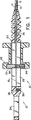
図1は本発明の第一実施形態の基端の部分断面側面図である。
図1aは本発明の好適実施形態における二つの無性部品からなる二部品スプールの無声部品の一つの平面図である。
図1bは二部品スプールの無性部品の一つの側面図である。
図1cは二部品スプールの無性部品の一つの基端面図である。
図1dは二部品スプールの無性部品の一つの末端面図である。
図1eは二部品スプールの二つの無性部品の板バネ式の係止を示した略破断面図である。
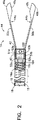
図2は顎状部材が開いた状態における本発明の第一実施形態の末端の拡大透過側面図である。
図3は本発明の第一実施形態の末端の拡大分解側面図である。
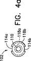
図4aおよび図4bはそれぞれ図3のネジ部材の前面図および図3のワッシャの前面図である。
図4cは図3で示した顎状部材組立体のアームの線C−Cに沿った断面図である。
図5は顎状部材が閉まった状態における本発明の第一実施形態の末端の拡大透過側面図である。
図6は本発明の第一実施形態の末端の拡大透過頂面図である。
図7aから図7eは生態組織抽出動作の流れを示した第一実施形態の末端の拡大透過側面図である。
図7fから図7hは図6と同様の図であってシリンダのナイフのように鋭利な末端エッジの切断動作を示した図である。
図8aは制御ワイヤの連結形態の異なる実施形態の拡大破断側面図である。
図8bは図10aの線B−Bに沿った断面図である。
図9aは図8aと同様の図であって制御ワイヤの連結形態の更に異なる実施形態を示した図である。
図9bは図9aの線B−Bに沿った断面図である。
図10は本発明の第二実施形態の部分断面破断側面図である。
図10aは顎状部材が開いた状態における図10に示した本発明の第二実施形態の押出ロッドおよび外側チューブへの顎状部材組立体の連結形態を示した拡大透過側面図である。
図11はコイルの末端への顎状部材の取付け形態の他の実施形態の分解斜視図である。
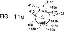
図11aは図11の線11a−11aに沿った断面図である。
図11bは顎状部材がコイルの末端に連結された状態における図11と同様の図である。
図12はコイルの末端への顎状部材の取付け形態の他の実施形態の拡大分解側面図である。
図12aは図12の実施形態の顎状部材のアームの破断斜視図である。
図12bは部分的に組み立てられた状態における図12に示した実施形態の破断側面図である。
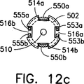
図12cは図12bの線12c−12cに沿った断面図である。
図13はコイルの末端への顎状部材の取付け形態の現在のところ好適な実施形態の分解側面図である。
図13aは図13のネジ部材の拡大末端面図である。
図13bはコイルの末端への取付けに先立って組み立てられた図13の実施形態の部分透過縮小側面図である。
図14は制御ワイヤの末端への円筒形のスリーブの連結形態の他の実施形態の拡大側面図である。
図14aは図13の実施形態の頂面図である。
図14bは図13の線13b−13bに沿った拡大断面図である。
発明を実施するための最良の形態
図1から図6には超弾性および可撓性を有する顎状部材組立体を備えた多サンプル生検用切断器の第一実施形態が示されており、これは基部ハンドル部分12と末端作動体部分14とを有する。可撓性を有するコイル16とコイル16を通って延びる軸線方向に移動可能な制御ワイヤ18とが基部ハンドル部分12を末端作動体部分14に連結する。好ましくはコイル16は実質的にその全長にわたって延びるPTFE、FEPまたはポリオレフィン製の鞘15と基部ハンドル部分12から延びてコイルの一部を覆う歪み解放スリーブ17とで覆われる。元々、コイル16は効果的な内ネジを備えているため、好ましくは研磨された平坦部16bであるコイルの開放末端16aにおいて後に詳述する適合ネジを備えたネジ部材を受容できる。制御ワイヤ18は好ましくは可撓性を有するが長手方向においては非弾性的であり、理想的には304鋼から作製され、その外径は約0.017〜0.018インチである。基部ハンドル部分12は中央シャフト20と移動可能なスプール(spool)22とを有する。中央シャフト20の基端は親指リング24を備え、中央シャフト20の末端には長手方向に延びる穴26が形成される。穴26の基端から親指リング24の末端の先端まで長手方向にスロット28が延びる。移動可能なスプール22は中央シャフト20のスロット28を通る横断部材30を備える。横断部材30は中央の貫通穴32と径方向において係合する設定ネジ34とを備える。本発明の第一実施形態では親指リング24の末端における中央シャフト20には短い穴36と径方向において係合する設定ネジ38とが配設され、短い穴36は長手方向に延びるスロット28と連通している。本発明の第一実施形態ではコイル16の基端は横断部材30の中央貫通穴32内へと延び、そこに設定ネジ34により固定される。制御ワイヤ18の基端はスロット28を通って短い穴36内に挿入され、そこに設定ネジ38により保持される。なお、中央シャフト20とスプール22とが相対的に動くことにより制御ワイヤ18がコイル16に対して相対的に動くことは当業者には前述から明らかである。この動きにより後に詳述するように端部作動体が作動される。
本発明の好適実施形態ではスナップ式に組み合わされる二つの無性部品からなる二部品スプールが用いられる。図1aから図1eはスナップ式に組み合わされる二部品スプールの各無性部品222a(222b)の主な特徴を示している。同一である二つの無性部品222a(222b)はそれぞれスプールの半体である。各無性部品222a(222b)はスプールの外郭を形どる実質的に半円筒形をしている。無性部品222a(222b)の全長にわたって延びる半円筒形状の凹部226a(226b)内ではコイル係合部材224a(224b)が径方向内方へ向かって延びている。各無性部品222a(222b)は直径方向において互いに反対側に位置する一対の係止タブ228a(228b)、230a(230b)と直径方向において互いに反対側に位置する一対のタブ受容スロット232a(232b)、234a(234b)とを備える。さらに各無性部品222a(222b)は直径方向において互いに反対側に位置する一対の案内ピン236a(236b)、238a(238b)と直径方向において互いに反対側に位置する一対のピン受容穴240a(240b)、242a(242b)とを備える。なお二つの無性部品222a、222bが組み立てられたときには無性部品222aの案内ピン236a、238aがそれぞれ無性部品222bのピン受容穴240b、242bに入り、無性部品222aの係止タブ228a、230aがそれぞれ無性部品222bのタブ受容スロット232b、234bに入ることは明らかである。同様に無性部品222bの案内ピン236b、238bはそれぞれ無性部品222aのピン受容穴240a、242aに入り、無性部品222bの係止タブ228b、230bはそれぞれ無性部品222aのタブ受容スロット232a、234aに入る。これら無性部品をスナップ式に組み合わせるのに先立ってかしめバンド(図示せず)を端部に備えたコイル16の基端(図1参照)がコイル係合部材224a、224bの間に配置される。これら無性部品222a、222bが組み立てられたときには各コイル係合部材224a、224bがコイルの基端をしっかりと保持する。
二部品スプールの好適実施形態のタブ受容スロットは二つの無性部品が離れることを禁止するために板バネを備える。図1eは無性部品222aの係止タブ228aが無性部品222bのタブ受容スロット232bに係合するときの係止タブ228aに関する板バネを略図的に示している。図1eに示したようにタブ受容スロット232bは垂れ下がったアーム233bにより部分的に塞がれており、アーム233bは係止タブ228aがタブ受容スロット232bに入ってアーム233bと係合したときに板バネのような機能をする。アーム233bは係止タブ228aがタブ受容スロット232bに入ったあとにおいて係止タブ228aがタブ受容スロット232bから出てしまうことを防止する。
図2から図6を参照すると、端部作動体部分14は好ましくはナイフのように鋭利な末端エッジ42を有する円筒形のスリーブ40と顎状部材組立体44とを有する。顎状部材組立体44は一対の端部作動体44a、44bとネジ部材102とワッシャまたは保持スリーブ104とを有する。各端部作動体44a、44bは好ましくはナイフのように鋭利なリム48a、48b(または後に詳述するように径方向に延びるように配設された歯)を有する顎状部材椀部46a、46bと顎状部材椀部46a、46bから基端方向に向かって延びる弾性を有する好ましくは幅の狭いアーム50a、50bとを有する。幅の狭いアーム50a、50bはその基端51a、51bに鋭く下降するように角度をつけられた鋭角度付き部分52a、52bと、緩やかに角度をつけられた緩角度付き部分53a、53bとを有する。少なくともアーム50a、50bの緩角度付き部分53a、53b、好ましくはアーム50a、50bの全体がNitinol(ニッケルチタン合金)のような超弾性形状記憶金属で作製され、(アーム50a、50bの緩角度付き部分53a、53bにより)互いに離れるように付勢され、このため顎状部材椀部46a、46bが互いに離れるようにされる。さらにアーム50a、50bと顎状部材46a、46bとが一体であることが好ましいため、顎状部材は好ましくは超弾性または形状記憶金属で作製される。しかしながらアームおよび顎状部材全体を超弾性または形状記憶金属で作製することが好ましいが顎状部材椀部46a、46bと顎状部材組立体44の基端51a−b、51a−bとを他の材料で作製してこれらを従来の適切な手段により弾性を有するアーム50a、50bに取り付けてもよい。
本発明の第一実施形態では各アーム50a、50bの基端51a、51bは図3および図4に明示した中空のネジ部材102とワッシャ104とのかしめ/係止によりコイル16の末端16aに連結される。ネジ部材102は実質的に円筒形であり、概してヘッド部分106とネジ部分108とネジ部材102の中央軸線に沿って延びる円筒形の貫通穴110とを有する。貫通穴110の大きさは制御ワイヤ18を受容でき且つ制御ワイヤ18の横方向への運動を可能とする大きさである。ヘッド部分106の末端112の直径はコイル16の外径と実質的に等しく、ヘッド部分106の末端112はヘッド部分106の末端112の外周に互いに反対側に位置する二つの溝114a、114b(図4a参照)を備える。溝114a、114bの大きさは幅の狭いアーム50a、50bの各々の基端51a、51bの鋭角度付き部分52a、52bを受容できる大きさである。ヘッド部分106の基端116は先端を切り取られた円錐形(すなわち、円錐台形)とされ、ヘッド部分106の末端112に直径が大きいほうの部分118bを有し、ネジ部分108の末端120に直径が小さいほうの部分118aを有する。ネジ部分108の直径はコイル16の内径に実質的に等しく、ネジ部分108の基端122はコイル16の末端16aの内部に係止するように係合するためのネジ124を有する。
ワッシャ104は実質的に円筒形であり、基部分128と末端部分130とを有する貫通穴126を有する。貫通穴126の末端部分128は先端を切り取られた円錐形とされ、そこから基部分130が延びている。なお、ワッシャ104の貫通穴126はネジ部材102のヘッド部分106の基端116およびネジ部材102のネジ部分108の末端120と実質的に同じ形状である。また、ワッシャ104の貫通穴126の大きさは幅の狭いアーム50a、50bの基端51a、51bの段付き部分52a、52bが上述のようにネジ部材102の溝114a−bに配置されたときにネジ部材102のヘッド部分106の基端116およびネジ部材102のネジ部分108の末端125に係合する大きさである。それからネジ部材102のネジ部分108の基端120はコイル16の末端16aの内部に螺合される。図2および図3に示したようにワッシャ104はネジ部材102のヘッド部分106とコイル16の末端16aとの間に止められる。したがって幅の狭いアーム50a、50bの基端51a、51bの段付き部分52a、52bはワッシャ104とネジ部材102との間に止められる。
図4cに示したように端部作動体の好適なアーム50a、50bは内側湾曲壁および外側湾曲壁55a、55b、56a、56bを備えた実質的に断面円弧形状である。なお円弧形状は顎状部材44a、44bから鋭角度付きの基部分52a、52bまで幅の狭いアームの全長につけられる。この構成では後述するようにチューブ40がアーム上を容易に摺動する。さらに顎状部材44a、44bの鋭角度付きの基部分52a、52bがネジ部材102のヘッド部分106の末端112の外周の溝114a、114b(図4a参照)に適合して係合する。
図2、図5および図6を参照すると、円筒形のスリーブ40に制御ワイヤ18の曲げられた端部18aと係合する横方向に延びる穴45を設けることにより制御ワイヤ18の末端にスリーブ40が連結される。図示したように制御ワイヤ18の曲げられた端部18aはスリーブ40の側部の穴45に溶接される。しかしながら後述するように他の方法により制御ワイヤをスリーブに連結することも可能である。円筒形のスリーブ40は円筒形のワッシャ104およびネジ部材102のヘッド部分106上に摺動可能に取り付けられ、弾性を有する円弧形状のアーム50a、50b上を軸線方向に可動であるため緩やかに曲げられた部分53a、53bにおいてアームを曲げ、図5で示したように顎状部材46a、46bを閉じる。弾性を有するアーム50a、50bが超弾性を有する金属から作製されるため、これらアームはスリーブ40がいったん後退せしめられるとアームの元の開いた位置(図2参照)に直ぐに戻る。さらにアーム50a、50b上でシリンダスリーブ40を前後に繰り返し摺動させたあとでさえも上述した超弾性を有する金属の特性により顎状部材組立体44がその元の形状を維持する。
図6に示したように顎状部材椀部46a、46bは線47で示された最も幅の広い点を備えた対称的ではあるが長円形をなす外形を有する。線47の末端側では顎状部材椀部は実質的に半球状であり、線47の基端側では顎状部材椀部は実質的に半楕円状である。顎状部材椀部はこれらが図5に示したように閉じられたときにリムが実質的に整列するように配設される。また図5および図6に示したように顎状部材椀部46a、46bの側壁57、57b、59a、59bはアーム50a、50bに向かってテーパがつけられ、顎状部材椀部からアームまで滑らかに変化する。
上述および図1から図6を参照すると、スプール22と中央シャフト20とが相対的に軸線方向に移動せしめられると、同様に円筒形のスリーブ40と端部作動体44a、44bとが図2に示した位置から図5に示した位置まで或いはその逆に相対的に軸線方向に移動せしめられることが当業者には明らかである。スプール22と中央シャフト20とが概ね図1に示した位置にあるときには円筒形のスリーブ40と端部作動体44a、44bとは概ね図2に示した位置にある、すなわち顎状部材が開かれている。したがってスプール22が親指リング24に向かって或いはその逆に移動せしめられると円筒形のスリーブ40および端部作動体44a、44bは概ね図4で示した位置になっている、すなわち顎状部材が閉じられている。さらに親指リング24をスプール22に対して相対的に動かすと、円筒形のスリーブ40が端部作動体44a、44bに対してその逆ではなく相対的に移動せしめられるため、親指リング24をスプール22に対して相対的に動かすのがその逆に動かすよりも好ましいことは明らかである。これは顎状部材が閉じられる間に端部作動体が組織サンプルから離れないので望ましい。
図7aから図7eには本発明の多サンプル生検用切断器の動作が順に略図的に示されている。図7aに示したように抽出されるべき組織60周辺に顎状部材椀部46a、46bを配置することにより第一の組織サンプルがとられる。上述のように生検用切断器10のハンドル12を作動すると円筒形のスリーブ40が末端方向へと顎状部材組立体44の幅の狭いアーム50a、50b上を概ね図7bに示した位置まで移動せしめられる。スリーブ40がこの位置に向かって移動せしめられたときには顎状部材椀部46a、46bが互いに近い位置となり、顎状部材椀部46a、46bの鋭利なリム48a、48bが組織60と係合してこの組織60に噛みつく。同時に図7fから図7hに示したようにスリーブ40のナイフのように鋭利なエッジ42が顎状部材椀部46a、46bの横側から延びる組織60を切断する。このため組織60の第一のサンプル60aが顎状部材椀部46a、46bの間に捕らえられ、組織60から切り取られる。なおコイル16の全長に沿って好ましくは延びる収縮ラップまたは鞘15によりコイル16が長手方向において堅くなっているため噛みついている間にコイル16が自由に伸びることはない。所望により収縮ラップまたは鞘の代わりにワイヤを用いることもできる。この場合、スリーブが前方へと移動せしめられて噛みつき動作が実行されるときにコイルを緊張状態に維持し且つコイルが伸びてしまうことを防止するように一般的には平坦なワイヤをコイルの基端および末端に取り付ける。
端部作動体44a、44bが概ね図7bに示した位置にある状態で多サンプル生検用切断器10が組織抽出のために他の組織領域に再配置される。生検用切断器10のハンドル12が上述したように作動せしめられて円筒形のスリーブ40が顎状部材組立体44の幅の狭いアーム50a、50b上を基端方向へと概ね図7cに示した位置まで移動せしめられる。スリーブ40がこの位置に向かって移動せしめられると顎状部材椀部46a、46bがそれぞれのアーム50a、50bの緩やかに曲げられた部分53a、53bにおける弾性特性により離れるように付勢される。それから顎状部材椀部が組織抽出のために第二の組織61周辺に配置される。そして図7aおよび図7bを参照して説明した手順が繰り返される。しかしながらこの場合に顎状部材椀部46a、46bが所定位置とされると図7cに示したように組織61が第一のサンプル60aを基端方向へと顎状部材椀部46a、46bから離れるように幅の狭いアーム50a、50bの間の空間内へと押す。なお組織サンプル60aが一般的にはゴム質で粘着性があって柔軟であり、端部作動体44a、44bの幅の狭いアーム50a、50bの一方または両方に貼りついてこれらアームに沿って移動することは当業者には明らかである。またサンプル同士も互いに貼りつく。サンプル61aを組織61からとる際に両サンプル60aおよび61aは図7dに示したように端部作動体44a、44bの幅の狭いアーム50a、50bの間に安全に捕らえられる。アーム50a、50bの間の空間がサンプル60a、61aなどで満たされるまで図7aから図7dを参照して説明した手順が図7eで示したように繰り返される。本発明の現在のところ好適な実施形態によれば、顎状部材組立体のアームの間には四つから六つのサンプルを捕獲できる。端部作動体の現在のところ好適な寸法は長さが約0.45インチで高さが約0.095インチである。
図7fから図7hは図7aおよび図7bの側面図で示した一連の動作の頂面図である。図7fの頂面図に示したように組織60は顎状部材椀部46a、46bの側部を越えて延在する。シリンダ40のナイフのように鋭利な末端エッジ42が顎状部材椀部を越えて延在する組織60を切断するため、図7gおよび図7hに示したようにサンプル60aが組織60から切り取られる。
上述したように制御ワイヤ18の末端18aを円筒形のスリーブ40に連結するには溶接以外に幾つかの方法がある。特に図8aから図9bには制御ワイヤ18の末端をスリーブに連結する他の二つの機構が示されている。
図8aおよび図8bに示したように制御ワイヤ18の末端18aはZ形状の曲げ部を備える。円筒形のスリーブ40の側壁には互いに間隔を開けた二つの半円形の穴145a、145bが打ち抜き加工され、これら穴145a、145bの間には曲げ可能な幅の狭い細長片145cが残される。幅の狭い細長片145cは制御ワイヤ18の末端18aを収容するのに十分な距離だけ径方向内方へ曲げられている。制御ワイヤ18の末端18aのZ形状の曲げ部は図8aおよび図8bに示したように幅の狭い細長片145cと半円形の穴145a、145bの間に形成された空間に挿入される。
図9aおよび図9bに示したように円筒形のスリーブ40の側壁には第一の穴245aと第一の穴245aにより囲まれた第二の穴245cとが打ち抜き加工される。第一の穴245aは好ましくは長方形、半円形または台形の形をしており、図9bに明示したように径方向内方へ曲げ可能なタブ245bを形成する。制御ワイヤ18の末端18aのZ形状の曲げ部は図9aおよび図9bに示したように曲げ可能なタブ245bの第二の穴245cに挿入される。
図10および図10aは、生検場所が内視鏡の内腔の長い曲がりくねった通路を通してではなく比較的短くて直接的な通路において接触可能であるような頸部生検用切断処置または他の腹壁鏡生検用切断処置に特に適した本発明の他の実施形態の多サンプル生検用切断器310を示す。本実施形態の基部作動機構312は固定されたハンドル部分324と固定されたハンドル部分324に枢動ピン323により連結された可動レバー部分322とを備える。基部作動機構312の可動レバー部分322には中空のチューブ340がその基端において横断ピン341または他の適切な締結手段により連結される。チューブ340の末端340aはナイフのように鋭利なエッジ342を備える。チューブ340内を比較的剛性が高いロッド318が延びており、その基端において横断ピン319または他の適切な締結手段により前記固定されたハンドル部分324に連結される。ロッド318の末端318aは中空であり、ロッド318の末端318aには外ネジを備えたネジ部材302を収容するためのネジ370を備えた内ネジが切られる。
図10aに明示したようにロッド318の末端は端部作動体344a、344bとネジ部材302とワッシャ304とを有する顎状部材組立体344に連結される。特に端部作動体344a、344bの幅の狭いアーム350a、350bの角度をつけられた基端352a、352bはワッシャ304と剛性の高いロッド318のネジを切られた中空の末端318aに螺合されるネジ部材302との間に締結される。
図10に示したように固定されたハンドル部分324は下方の親指リング324aを備え、可動レバー部分322は下方の指リング322aを備える。可動レバー部分322の上端部322bは横断ピン341と係合するためのスロット322cを備え、ロッド318は横断ピンが通るスロット317を備える。基部作動機構312が従来のはさみ式の握り動作を用いて作動せしめられることは当業者には明らかである。基部作動機構312の可動レバー部分322を矢印321で示したように枢動するとチューブ340が矢印339で示したように直線的に動かされる。なおスロット317および322cの大きさはチューブ340の運動を制限する大きさであることは明らかである。端部作動体344a、344bのアーム350a、350bの形状により、チューブ340がロッド318に対して相対的に動かされるとチューブ340がアーム350a、350bに乗って移動し、上述したように顎状部材が開いたり閉じたりする。なお所望により基部作動機構312を図1および図2を参照して説明した可撓性を有するコイルおよび引張ワイヤと共に用いてもよい。逆に図1を参照して説明した作動気候12を図10のチューブおよびロッドを備えた構成と共に用いてもよい。なお押出ロッド318を不動ハンドル324に固定し且つチューブ340をレバー322と共に可動とする代わりに押出ロッド318を可動とし、チューブ340を固定してもよい。このような構成ではレバーをハンドルに対して相対的に動かすと端部作動体344a、344bがチューブ340内に引き込まれて顎状部材が閉じ、顎状部材およびチューブ340の鋭利な端部342が組織を切断する。
なお図1から図10aに示した多サンプル生検用切断器の実施形態全てが焼灼器を受容する能力を有することができる。例えば図10に示したように剛性の高いロッド318と接触し且つハンドル312の固定部分324から出るように延びる焼灼器接触子398を設ける。さらにチューブ340が収縮ラップまたは他の絶縁物399を備えるのも好ましい。この構成では焼灼器の電流が焼灼器接触子398に供給されると顎状部材組立体344はロッド318との接続を介して電化せしめられる。一般的にはサンプルが得られて顎状部材がまだ手術領域にある状態で手術領域からサンプルを切断したあとで焼灼が実行される。患者の体が第二の電極(接地)として機能するため電流は顎状部材から患者の手術領域に流れ、このため顎状部材内のサンプルを焼灼するというより手術領域を焼灼する。
次に図11、図11aおよび図11bを参照すると、別の実施形態の顎状部材組立体444は一対の端部作動体444a、444bと顎状部材を可撓性を有するコイル16の末端16aに連結するための取付けネジ部材402とを有する。各端部作動体444a、444bは顎状部材椀部446a、446bと弾性を有し且つ好ましくは幅の狭いアーム450a、450bとを有し、これらアームは顎状部材椀部446a、446bから基端方向へと延びる。顎状部材椀部446a、446bは好ましくは同時係属中であって本願と同一人が所有する1995年3月28日に出願された米国特許出願番号08/412058号に記載された閉鎖カム447a、447bを備え、上記米国出願は本願の一部をなす。幅の狭いアーム450a、450bはその基端451a、451bに取付け穴452a、452bを備えると共に緩やかに角度をつけられた緩角度付き部分453a、453bを備える。少なくともアーム450a、450bの緩角度付き部分453a、453b、好ましくはアーム450a、450b全体がNitinolのような超弾性金属から作製され、(アーム450a、450bの角度をつけられた部分453a、453bにより)互いに離れるように付勢されているため、顎状部材椀部446a、446bが離される(図11b参照)。さらにアーム450a、450bおよび顎状部材446a、446bが好ましくは一体であるため、顎状部材は好ましくは超弾性金属から作製される。
図11、図11aおよび図11bに示した実施形態では図11aおよび図11bに明示したように各アーム450a、450bの基端451a、451bは中空のネジ部材402とのかしめ/係止によりコイル16の末端16aに連結される。ネジ部材402は実質的に円筒形であり、概ねヘッド部分406とネジ部分408とネジ部材402の中央軸線方向に延びる円筒形の貫通穴410とを有する。貫通穴410の大きさは図5から図7を参照して説明したように制御ワイヤ18を受容でき且つ制御ワイヤ18が横方向へと動ける大きさである。ヘッド部分406の直径はコイル16の外径と実質的に等しく、ヘッド部分406はその外周に互いに反対側に位置する二つの溝414a、414bを備える。溝414a、414bは側部の尖端415a、415bと盛り上がったピン417a、417bとを備え、溝の大きさは幅の狭い各アーム450a、450bの基端451a、451bを受容する大きさである。アーム450a、450bの基端451a、451bはそれぞれ溝414a、414b内に配置され、ピン417a、417bがそれぞれ取付け穴452a、452bに係合する。ピン417a、417bはリベットのように平らになっており、溝の尖端415a、415bは図11aおよび図11bに明示したようにアーム上に畳まれる。中空のネジ部材402のネジ部分408の直径はコイル16の内径に実質的に等しく、ネジ部分408は図11bに示したようにコイル16の末端16aの内部に螺合するように係合する。
図12および図12aから図12cは可撓性を有するコイルの末端に顎状部材を取り付ける別の実施形態を示している。顎状部材組立体544は一対の端部作動体544a、544bと顎状部材を可撓性を有するコイル16の末端16aに連結するための取付け用ネジ部材502とを有する。各端部作動体544a、544bは上述した実施形態と実質的に同じ顎状部材椀部(図示せず)と弾性を有し且つ好ましくは幅の狭いアーム550a、550bとを有し、これらアームは顎状部材椀部から基端方向へと延びる。幅の狭いアーム550a、550bはその基端551a、551bに半円筒形の部分552a、552bを備え、これら半円筒形の部分は基端方向へと延びる一対のタブ553a、553b、555a、555bとして終端している。
図12および図12aから図12cに示した実施形態では各アーム550a、550bの基端551a、551bは図12bおよび図12cに明示したように中空でネジ部材502によりコイル16の末端16aに連結される。ネジ部材502は実質的に円筒形であり、概してヘッド部分506とネジ部分508とネジ部材502の中央軸線に沿って延びる円筒形の貫通穴510とを有する。貫通穴510の大きさは図5から図7を参照して説明したように制御ワイヤ18を受容でき且つ制御ワイヤ18が横方向へ動ける大きさである。ヘッド部分506の末端の直径はコイル16の外径に実質的に等しく、ヘッド部分506はその外周に互いに反対側に位置する二対の溝514a、514b、516a、516bを備える。溝の大きさは図12bおよび図12cに明示したように半円筒形の部分552a、552bがヘッド部分506の直径の小さな基部分上にあり且つタブ553a、553bが溝516a内にあり且つタブ555a、555bが溝516b内にある状態で幅の狭い各アーム550a、550bの基端551a、551bを受容できる大きさである。中空のネジ部材502のネジ部分508の直径はコイル16の内径に実質的に等しく、ネジ部分508は上述したようにコイル16の末端16aの内部に螺合するように係合する。
図13、図13aおよび図13bは顎状部材組立体をコイルの末端に連結するのに現在のところ好適な実施形態を示している。本実施形態では顎状部材組立体560は一対の端部作動体562a、562bと取付け用ネジ部材564と保持スリーブまたはワッシャ566とを有する。各端部作動体562a、562bは顎状部材椀部568a、568bと弾性を有し且つ好ましくは幅の狭いアーム570a、570bとを有し、これらアームは顎状部材椀部から基端方向へと延びている。各アーム570a、570bの基端は取付け穴572a、572bを備える。端部作動体の他の全ての特徴は上述した端部作動体の数々の特徴を含む。取付け用ネジ部材564は上述した取付け用ネジ部材402と同様である。取付け用ネジ部材402は実質的に円筒形であり、ヘッド部分564aとネジ部分564bと貫通穴564cと直径方向に互いに反対側に位置する一対のアーム受容溝564d、564eとを有し、各アーム受容溝は直立したピン564f、564gを備える。本実施形態のネジ部材のヘッド部分564aの基部分564hの直径は小さくされており、保持スリーブまたはワッシャ566の内径に実質的に等しい。直立したピン564f、564gはネジ部材のヘッド部分564aの基部分564hに位置する。上述したように端部作動体562a、562bはそれぞれのアーム570a、570bを溝546d、546e内に配置し、それぞれの取付け穴572a、572bがそれぞれのピン564f、564gに係合することによりネジ部材564に連結される。このようにアームがネジ部材に対して配設されたあとにスリーブまたはワッシャ566がネジ部材のヘッド部分564aの基部分564h上に配置され、アームの基端がスリーブとネジ部材のヘッド部分との間に捕らえられる。それからネジ部材のネジ部分564bが上述したようにコイル(図示せず)の末端に連結され、スリーブまたはワッシャ566が上述したようにコイルとネジ部材のヘッド部分との間に捕らえられる。
上述したように顎状部材椀部は制御ワイヤに連結された円筒形のスリーブを動かすことにより開いたり閉じたりする。図14、図14aおよび図14bは可撓性を有するコイル16の末端16aに連結された顎状部材組立体644を開いたり閉じたりするために制御ワイヤ618の末端618aに連結された別の実施形態の円筒形のスリーブ640を示している。顎状部材組立体644は上述した数々の顎状部材組立体と実質的に同じである。特に顎状部材組立体は互いに狭い間隔を開けた二つのアーム650a、650bを有する。図14、図14aおよび図14bの実施形態では制御ワイヤ618の末端618aには横断部材628が連結されている。横断部材628は円盤状であり、互いに対向する位置にある実質的に互いに平行な二つの側辺628a、628bと円筒形のスリーブ640の内径に一致した湾曲率を有する二つの湾曲側辺628c、628dと中央の穴628eとを有する。互いに平行な側辺628aおよび628bの間の距離は顎状部材組立体のアーム650a、650bの内面の間の距離より短く、湾曲側辺628cおよび628dの間の距離は円筒形のスリーブ640の内径に実質的に等しい。穴628eの直径は制御ワイヤ618の直径に実質的に等しい。制御ワイヤ618は図14および図14aに明示したように制御ワイヤの末端618aを穴628eに挿入して制御ワイヤを横断部材の両側にかしめることにより横断部材628に連結される。横断部材は図14aおよび図14bに明示したようにそれがアーム650aおよび650bの間で自由に延びるように顎状部材組立体644に対して整列せしめられる。円筒形のスリーブ640は図14aに明示したように参照番号699の箇所においてスリーブを横断部材628の両側にかしめることにより横断部材に連結される。
内視鏡式の多サンプル生検用切断器の幾つかの実施形態を説明し且つ例示した。本発明の特別な実施形態を説明したがこれは本発明を限定するものではなく本発明の範囲は当該技術分野において可能な範囲であり、明細書の内容も同様である。したがって顎状部材組立体は特別に超弾性を有する金属から作製されると記載したが、本願で開示したのと同一または類似の機能を達成する他の超弾性を有する合金を用いることもできる。例えば顎状部材組立体はニッケルチタン合金から作製されると記載したが、これは例えば鉄白金、銀カドミウム、ニッケルアルミニウム、マンガン銅、銅亜鉛、ニッケルタリウムまたは他の超弾性合金から作製してもよい。さらに本発明の装置では手術領域から取り出すことなく多数の生態組織を得られると記載したが、所望により一度に一つの生態組織を得ることもできる。実際には内視鏡式検査器具は生態組織をとるためだけでなく解剖器具としても用いられる。解剖器具としての実施形態ではアームを閉鎖するチューブは鋭利な端部を有してはおらず、端部作動体は顎状部材椀部を有するのではなく、へら状のものまたは鋭利なものである。さらに本発明の作動機構の特別な形状を開示したが他のタイプの作動機構を用いることもできる。またコイルおよび制御ワイヤの端部の特定の連結方法を開示したが他のタイプの連結を用いて同様の結果を得ることもできる。同様に剛性が高いチューブおよびロッドの端部の特定の連結方法を示したが他のタイプの連結方法を用いることもできる。さらに顎状部材組立体について特別な形状を開示したが他の形状を用いることもできる。例えば顎状部材に鋭利なエッジを設けることが好ましいが、このエッジの代わりに顎状部材が鋭利なシリンダと協動して切断が可能な鋭利な歯を備えてもよい。さらに第二の実施形態において内部のロッドが静止しており、外部のチューブが調節可能であると示したが、外側のチューブが静止しており、ロッドが調節可能であってもよい。以上、本発明の精神および請求の範囲を逸脱することなく本発明を修正することができることは当業者には明らかである。Technical field
The present invention relates to an endoscopic surgical instrument. In particular, the present invention relates to a superelastic jaw member assembly for multi-sample endoscopic instruments.
Background art
Endoscopic biopsy treatment is generally performed with an endoscope and an endoscopic biopsy forceps device (biopsy cutter). An endoscope is a long, flexible tube that holds a fiberglass transmission device and has a narrow lumen into which a biopsy cutter is inserted. A biopsy cutter generally has a long, flexible coil with a pair of jaws positioned opposite each other at the distal end and manually actuated means at the proximal end. When the actuating means is moved manually, the jaw member opens and closes. During the extraction operation for the biopsy, the surgeon guides the endoscope to the biopsy site while looking at the biopsy site through the glass fiber transmission device of the endoscope. The biopsy cutter is inserted into the narrow lumen of the endoscope until jaws located on opposite sides reach the biopsy site. The surgeon places the jaw member around the tissue to be extracted while looking at the biopsy site through the glass fiber transmission device of the endoscope, and operates the operating means to close the jaw member around the tissue. The tissue is then cut out and / or removed from the biopsy site with the tissue captured between the jaws of the biopsy cutter. The surgeon withdraws the biopsy cutter from the endoscope with the jaws closed and then opens the jaws to collect the biopsy sample.
Biopsy extraction procedures often require the collection of several tissue samples from the same or different biopsy locations. However, most biopsy cutters are limited to taking a single tissue sample, and after tissue collection the instrument must be withdrawn from the endoscope and again to collect a second tissue sample. Tissue must be collected before using the instrument. Most biopsy cutters are limited to a single tissue extraction because the space between the biopsy forceps jaws is limited. Several attempts have been made to provide an instrument that can take several tissue samples before the instrument is withdrawn and the sample is collected. Providing such an instrument requires a very small size due to the narrow endoscope lumen, and the instrument is flexible so that it can be inserted through the endoscope lumen. There is a problem that must be done. Accordingly, some known multi-sample biopsy instruments have been excluded from use with endoscopes due to size and rigidity. These are "punch and suction" type devices disclosed in Halpern et al. U.S. Pat. No. 3,989,033 and Whipple et al. U.S. Pat. No. 4,522,206. Both instruments have a hollow tube with a perforator at the distal end and a vacuum source connected to the proximal end. The tissue sample is cut with the punch and aspirated from the biopsy site through a hollow tube. However, it is generally understood that it is practically impossible to aspirate a tissue sample through a long and narrow flexible biopsy cutter.
Co-pending US patent application Ser. No. 08 / 189,937 discloses an endoscopic multi-sample biopsy cutter that can take multiple samples before the biopsy cutter is removed from the endoscope. The multi-sample biopsy cutter has a hollow outer member and an inner member extending through the outer member and movable axially. The proximal ends of the outer member and the inner member are connected to an actuator that moves in the axial direction relative to the other. The distal end of the outer member is connected to one of a cylinder or jaw assembly having a sharp distal edge and the distal end of the inner member is connected to the other. The jaw member assembly has a pair of jaw member collars, preferably with teeth, located on opposite sides of each other, each of these jaw member collars being connected to the base member by an elastic arm. . The arms are bent so that the jaw members are separated from each other. The base member is attached to the inside of the cylinder and the arm is retracted into the cylinder (or the cylinder extends over the arm) by moving the jaw assembly and the cylinder axially relative to each other. Then, the jaw-like member buttock is joined and the biting operation is performed. In this method, a number of samples are taken from the patient and stored in the jaw assembly before the biopsy cutter needs to be retrieved from the patient.
It has recently been recognized that a group of known alloys that exhibit unique elastic and flexible properties can be usefully applied in practice. These alloys exhibit an effect called shape memory alloy. This effect is such that when the alloy is plastically deformed from its original shape at a certain temperature, raising the temperature to a higher temperature completely restores the original shape. When restored to their original shape, these alloys generate movement or force or a combination of these as a function of temperature. Due to the unique atomic structure necessary to produce the shape memory effect, these alloys exhibit other properties such as superelasticity or pseudoelasticity.
The type of transformation that occurs in shape memory alloys is known as the martensitic transformation, which changes the material from a high temperature form called austenite to a low temperature form called martensite. For a given shape memory alloy, the transformation between the martensite and austenite forms occurs at a predictable temperature known as the transformation temperature.
In order for the alloy to have a shape memory effect, the alloy must first be bent into the shape to be memorized at room temperature. The alloy is then heated until it exhibits a high temperature form called the beta phase or parent phase, where the metal crystal structure shows the austenite form remembered by the metal crystal structure. The alloy is then quickly cooled so that the atoms in the alloy are rearranged into the martensitic crystal structure. The alloy is then bent into a new form that the alloy maintains as long as the temperature is below the transformation temperature. Thereafter, when the alloy is heated above the transformation temperature so that the molecular structure of the alloy returns to the austenite form, the alloy regains its initially memorized shape. Shape memory alloys have significantly increased elasticity compared to the same material that does not have superelasticity because the shape memory metal atoms move between the martensite form and the austenite form. It will not shift to a newly changed form.
Shape memory alloys also exhibit useful properties that are independent of temperature. In an alloy having a beta phase that produces martensite under stress, a unique elastic property called superelasticity or pseudoelasticity can be seen. The metal in a typical alloy having this property exhibits normal elastic behavior in the stressed state (i.e., a certain dimension becomes longer) until the critical stress at which the martensitic molecular structure begins to form is reached. When further stress is applied, the specimen continues to stretch as if it were plastically deformed. When the stress is removed, the martensite structure returns to the parent phase, that is, the austenite structure, the metal shrinks to its original dimensions and does not permanently deform.
Currently, the application of shape memory materials in medical devices is very limited. U.S. Pat. No. 4,925,445 to Sakamoto et al. Discloses a guide wire for a catheter having a rigid body and a flexible end made from a shape memory metal alloy with superelastic properties as described above. . The distal end of the guide wire is bent back so as to form a forward tip that is not sharp. Because the distal end is superelastic, the guide wire is guided through the patient's blood vessel without the risk of permanently deforming the tip of the wire to break the patient's vessel wall or incorrectly guide the wire. US Pat. No. 5,254,130 to Poncet et al. Similarly uses a shape memory alloy as the steering means for steering the push rod, the distal U-shaped key and the attached end effector. When the push rod extends outside the housing where the push rod is held prior to deployment, the push rod exhibits a remembered shape relative to the straight housing, thus maneuvering the end effector to the desired position. However, in addition to the steering function disclosed in the Sakamot et al. And Poncet et al. Patents, the superelasticity of shape memory alloys is not used in the field of medical devices.
Disclosure of the invention
Accordingly, an object of the present invention is to provide a jaw member assembly for a biopsy cutting device in which at least a part of the jaw member assembly is made of a metal having superelasticity.
Another object of the present invention is for an endoscopic multi-sample biopsy cutting device in which a jaw-shaped member arm has superelasticity and flexibility and is repeatedly returned to a desired position without being bent or deformed. It is an object of the present invention to provide a jaw member assembly.
Yet another object of the present invention is to provide a jaw assembly for an endoscopic multi-sample biopsy cutter that hardly deforms plastically even after the arms of the jaw assembly are repeatedly opened and closed. There is.
Another object of the present invention is to provide a jaw member assembly for an endoscopic multi-sample biopsy cutting device that is easy to assemble.
In order to achieve the above-described object, which will be described in detail later, a jaw member assembly, a tubular member, and an axially movable wire extending through the tubular member, both of the wire and the distal end of the tubular member are provided. An endoscopic living body having a pair of end effectors positioned opposite to each other and connected to a jaw member assembly, the jaw member assembly having elastic arms made of superelastic metal. A test cutter is provided. According to a first embodiment of the present invention, the proximal end of the elastic arm has an angled portion, while the distal end terminates as a jaw-like member collar of the end effector. It is preferably made of a metal having superelasticity. The elastic arm separates the jaw-shaped member collars from each other. Since the elastic arms are made from a superelastic alloy, they exhibit very high elasticity and durability even after many uses. Another embodiment of the jaw assembly has an arm having a mounting hole and a flange with a radially disposed tooth and a closure cam. In another embodiment, the jaw assembly has an arm having a semi-cylindrical base with a tab extending distally. Various types of mounting screw members are provided for connecting the proximal end of the arm of the jaw member to the distal end of the tubular member.
According to a preferred embodiment of the present invention, the tubular member is a flexible coil, and the base portion of each arm is located within the distal end of the tubular member by a screw member and washer (or holding sleeve) that are screwed into the coil. Attached to. The end of the wire is connected to a cylinder, preferably equipped with a sharp end edge like a knife. Numerous embodiments have been disclosed for connecting the ends of wires to a cylinder. The proximal ends of the coil and wire are coupled to manual actuation means for axially moving one of the coil and wire relative to the other. When the wire is moved relative to the coil in the axial direction, the cylinder is moved on the arm of the end effector and the neck of the jaw-like member collar, and the jaw-like member collar is engaged to perform the biting operation. .
In another embodiment of the present invention, a laparoscope type multi-sample biopsy cutter includes the super-elastic jaw-like member assembly of the present invention. This abdominoscope type multi-sample biopsy cutter comprises a relatively rigid hollow tube and a relatively rigid rod extending through the tube. The end of the rod is connected to the jaw assembly described in the first embodiment, and the end of the tube has a sharp edge like a knife similar to the cylinder edge described above. The proximal end of the rod is connected to the fixed portion of the handle, and the proximal end of the tube is connected to the movable lever portion of the handle. When the lever of the handle is moved, the tube is moved in the longitudinal direction relative to the rod, and the jaw-shaped member is closed as described above.
Other objects and features of the present invention will become apparent to those skilled in the art upon reference to the detailed description taken in conjunction with the drawings.
[Brief description of the drawings]
FIG. 1 is a partial cross-sectional side view of a proximal end of a first embodiment of the present invention.
FIG. 1a is a plan view of one silent part of a two-part spool of two non-parts according to a preferred embodiment of the present invention.
FIG. 1b is a side view of one of the free parts of the two-part spool.
FIG. 1c is a proximal view of one of the free parts of the two-part spool.
FIG. 1d is an end view of one of the free parts of the two-part spool.
FIG. 1e is a schematic broken sectional view showing the leaf spring type locking of two non-use parts of a two-part spool.
FIG. 2 is an enlarged transparent side view of the end of the first embodiment of the present invention with the jaw-shaped member open.
FIG. 3 is an enlarged exploded side view of the end of the first embodiment of the present invention.
4a and 4b are a front view of the screw member of FIG. 3 and a front view of the washer of FIG. 3, respectively.
4c is a cross-sectional view of the arm of the jaw assembly shown in FIG. 3, taken along line CC.
FIG. 5 is an enlarged transparent side view of the end of the first embodiment of the present invention with the jaw-shaped member closed.
FIG. 6 is an enlarged transparent top view of the end of the first embodiment of the present invention.
7a to 7e are enlarged transparent side views of the end of the first embodiment showing the flow of the ecological tissue extraction operation.
FIGS. 7f to 7h are views similar to FIG. 6 and show a cutting operation of a sharp end edge like a knife of a cylinder.
FIG. 8 a is an enlarged cutaway side view of a different embodiment of the connection form of the control wires.
FIG. 8b is a cross-sectional view along the line BB of FIG. 10a.
FIG. 9A is a view similar to FIG. 8A, showing a further different embodiment of the connection form of the control wires.
FIG. 9b is a cross-sectional view along line BB in FIG. 9a.
FIG. 10 is a partially sectional cutaway side view of the second embodiment of the present invention.
FIG. 10a is an enlarged transparent side view showing the coupling configuration of the jaw member assembly to the extrusion rod and the outer tube of the second embodiment of the present invention shown in FIG. 10 in a state where the jaw member is opened.
FIG. 11 is an exploded perspective view of another embodiment in which the jaw member is attached to the end of the coil.
11a is a cross-sectional view taken along line 11a-11a of FIG.
FIG. 11b is a view similar to FIG. 11 with the jaw member connected to the end of the coil.
FIG. 12 is an enlarged exploded side view of another embodiment of the attachment of the jaw member to the end of the coil.
12a is a cutaway perspective view of the arm of the jaw-like member of the embodiment of FIG.
12b is a cutaway side view of the embodiment shown in FIG. 12 in a partially assembled state.
12c is a cross-sectional view taken along
FIG. 13 is an exploded side view of the presently preferred embodiment of the attachment of the jaws to the end of the coil.
FIG. 13a is an enlarged end view of the screw member of FIG.
13b is a partially transparent reduced side view of the embodiment of FIG. 13 assembled prior to attachment of the coil to the end.
FIG. 14 is an enlarged side view of another embodiment of a connection of a cylindrical sleeve to the end of the control wire.
FIG. 14a is a top view of the embodiment of FIG.
14b is an enlarged cross-sectional view taken along line 13b-13b of FIG.
BEST MODE FOR CARRYING OUT THE INVENTION
FIGS. 1-6 show a first embodiment of a multi-sample biopsy cutter with a superelastic and flexible jaw assembly that includes a base handle portion 12 and a distal actuation. And a
In a preferred embodiment of the present invention, a two-part spool is used that consists of two free parts that are snapped together. FIGS. 1a to 1e show the main features of each of the non-parts 222a (222b) of a two-part spool that is snapped together. Two
The tab receiving slot of the preferred embodiment of the two-part spool includes a leaf spring to inhibit the two non-parts from separating. FIG. 1e schematically illustrates the leaf spring associated with the
Referring to FIGS. 2-6, the
In the first embodiment of the present invention, the base ends 51a and 51b of the
As shown in FIG. 4c, the
With reference to FIGS. 2, 5, and 6, the
As shown in FIG. 6, the
As described above and with reference to FIGS. 1-6, when the
7a to 7e schematically show the operation of the multisample biopsy cutting device of the present invention in sequence. As shown in FIG. 7a, a first tissue sample is taken by placing jaw-
With the
7f to 7h are top views of the series of operations shown in the side views of FIGS. 7a and 7b. As shown in the top view of FIG. 7f,
As described above, there are several methods other than welding for connecting the
As shown in FIGS. 8a and 8b, the
As shown in FIGS. 9a and 9b, a
FIGS. 10 and 10a illustrate a cervical biopsy cutting procedure where the biopsy site is accessible in a relatively short direct path rather than through a long tortuous path in the endoscope lumen or other FIG. 7 shows a
As clearly shown in FIG. 10 a, the distal end of the
As shown in FIG. 10, the fixed
It should be noted that all of the multi-sample biopsy cutting device embodiments shown in FIGS. 1-10a can have the ability to receive a cautery device. For example, as shown in FIG. 10, a
11, 11a and 11b, another embodiment
In the embodiment shown in FIGS. 11, 11 a, and 11 b, as clearly shown in FIGS. 11 a and 11 b, the base ends 451 a and 451 b of the
12 and 12a to 12c show another embodiment in which a jaw member is attached to the end of a flexible coil. The
In the embodiment shown in FIGS. 12 and 12a to 12c, the base ends 551a and 551b of each
FIGS. 13, 13a and 13b show a presently preferred embodiment for connecting the jaw assembly to the end of the coil. In this embodiment, the
As described above, the jaw member collar is opened and closed by moving the cylindrical sleeve connected to the control wire. 14, 14a and 14b show another implementation coupled to the
Several embodiments of an endoscopic multi-sample biopsy cutter have been described and illustrated. Although a specific embodiment of the present invention has been described, this is not intended to limit the present invention, and the scope of the present invention is a possible range in the technical field, and the contents of the specification are also the same. Thus, while the jaw assembly has been described as being made of a specially superelastic metal, other superelastic alloys that accomplish the same or similar functions as disclosed herein may be used. For example, although the jaw assembly has been described as being made from a nickel titanium alloy, it may be made from, for example, iron platinum, silver cadmium, nickel aluminum, manganese copper, copper zinc, nickel thallium or other superelastic alloys. Good. Furthermore, although it has been described that the apparatus of the present invention can obtain a large number of ecological tissues without being removed from the surgical area, one ecological tissue can be obtained at a time if desired. Actually, an endoscopic examination instrument is used not only for taking ecological tissue but also as a dissecting instrument. In an embodiment as a dissecting instrument, the tube that closes the arm does not have a sharp end, and the end effector does not have a jaw-like buttock, but is a spatula or sharp. . Furthermore, although a special configuration of the actuating mechanism of the present invention has been disclosed, other types of actuating mechanisms can be used. Also, although specific connection methods for the ends of the coil and control wire have been disclosed, other types of connections can be used to achieve similar results. Similarly, although a specific connection method for the ends of the rigid tube and rod has been shown, other types of connection methods can be used. Furthermore, although a special shape has been disclosed for the jaw member assembly, other shapes can be used. For example, it is preferable to provide a sharp edge on the jaw-like member, but instead of this edge, the jaw-like member may be provided with a sharp tooth capable of cutting in cooperation with a sharp cylinder. In the second embodiment, the inner rod is stationary and the outer tube is adjustable. However, the outer tube may be stationary and the rod may be adjustable. Thus, it will be apparent to one skilled in the art that modifications may be made to the invention without departing from the spirit and scope of the invention.
Claims (32)
Applications Claiming Priority (3)
| Application Number | Priority Date | Filing Date | Title |
|---|---|---|---|
| US08/440,327 | 1995-05-12 | ||
| US08/440,327 US5645075A (en) | 1992-02-18 | 1995-05-12 | Jaw assembly for an endoscopic instrument |
| PCT/US1996/006925 WO1996035382A1 (en) | 1995-05-12 | 1996-05-10 | Jaw assembly for an endoscopic instrument |
Publications (2)
| Publication Number | Publication Date |
|---|---|
| JPH11505144A JPH11505144A (en) | 1999-05-18 |
| JP3696621B2 true JP3696621B2 (en) | 2005-09-21 |
Family
ID=23748335
Family Applications (1)
| Application Number | Title | Priority Date | Filing Date |
|---|---|---|---|
| JP53433096A Expired - Fee Related JP3696621B2 (en) | 1995-05-12 | 1996-05-10 | Jaw-like member assembly for endoscopic inspection instruments |
Country Status (6)
| Country | Link |
|---|---|
| US (3) | US5645075A (en) |
| EP (2) | EP1350475B1 (en) |
| JP (1) | JP3696621B2 (en) |
| AU (1) | AU5748696A (en) |
| DE (2) | DE69636081T2 (en) |
| WO (1) | WO1996035382A1 (en) |
Families Citing this family (265)
| Publication number | Priority date | Publication date | Assignee | Title |
|---|---|---|---|---|
| US5645075A (en) * | 1992-02-18 | 1997-07-08 | Symbiosis Corporation | Jaw assembly for an endoscopic instrument |
| US5762069A (en) * | 1995-12-29 | 1998-06-09 | Akos Biomedical, Inc. | Multiple sample biopsy forceps |
| US6293282B1 (en) * | 1996-11-05 | 2001-09-25 | Jerome Lemelson | System and method for treating select tissue in living being |
| US7347828B2 (en) * | 1996-11-25 | 2008-03-25 | Boston Scientific Miami Corporation | Suction adapter for medical instrument |
| US6331165B1 (en) * | 1996-11-25 | 2001-12-18 | Scimed Life Systems, Inc. | Biopsy instrument having irrigation and aspiration capabilities |
| US6142956A (en) * | 1996-11-25 | 2000-11-07 | Symbiosis Corporation | Proximal actuation handle for a biopsy forceps instrument having irrigation and aspiration capabilities |
| US5897507A (en) | 1996-11-25 | 1999-04-27 | Symbiosis Corporation | Biopsy forceps instrument having irrigation and aspiration capabilities |
| AU6491198A (en) | 1997-03-13 | 1998-09-29 | Biomax Technologies, Inc. | Validating and processing fluorescence spectral data for detecting the rejectionof transplanted tissue |
| FR2766084A1 (en) * | 1997-07-21 | 1999-01-22 | Duche Mathieu J B | Supple or rigid endoscopic or coeloscopic surgical instrument |
| JPH11225951A (en) * | 1998-02-17 | 1999-08-24 | Olympus Optical Co Ltd | Treatment tool for endoscope |
| US5967997A (en) | 1998-04-30 | 1999-10-19 | Symbiosis Corporation | Endoscopic surgical instrument with deflectable and rotatable distal end |
| US6527767B2 (en) * | 1998-05-20 | 2003-03-04 | New England Medical Center | Cardiac ablation system and method for treatment of cardiac arrhythmias and transmyocardial revascularization |
| US6083150A (en) * | 1999-03-12 | 2000-07-04 | C. R. Bard, Inc. | Endoscopic multiple sample biopsy forceps |
| US6387110B1 (en) * | 1999-06-23 | 2002-05-14 | Smith & Nephew, Inc. | Coating for surgical blades |
| US6537205B1 (en) | 1999-10-14 | 2003-03-25 | Scimed Life Systems, Inc. | Endoscopic instrument system having reduced backlash control wire action |
| ITCE990004A1 (en) * | 1999-10-25 | 2000-01-25 | Mario Immacolato Paternuosto | VALVE FOR BIOPSY FORCEPS IN DIGESTIVE ENDOSCOPY |
| US6743185B2 (en) * | 2000-09-26 | 2004-06-01 | Scimed Life Systems, Inc. | Handle assembly for surgical instrument and method of making the assembly |
| AU2002235351A1 (en) | 2001-01-26 | 2002-08-06 | Osteotech, Inc. | Implant insertion tool |
| US11229472B2 (en) | 2001-06-12 | 2022-01-25 | Cilag Gmbh International | Modular battery powered handheld surgical instrument with multiple magnetic position sensors |
| US7094245B2 (en) | 2001-10-05 | 2006-08-22 | Scimed Life Systems, Inc. | Device and method for through the scope endoscopic hemostatic clipping |
| EP1439802A2 (en) * | 2001-10-30 | 2004-07-28 | Osteotech, Inc. | Bone implant and insertion tools |
| US6989020B2 (en) | 2001-11-15 | 2006-01-24 | Cordis Neurovascular, Inc. | Embolic coil retrieval system |
| US20030097146A1 (en) * | 2001-11-19 | 2003-05-22 | Scimed Life Systems, Inc. | Endoscopic surgical instrument |
| US6673078B1 (en) * | 2002-07-24 | 2004-01-06 | Robert H. Muncie | Surgical wire and pin extractor |
| US7294139B1 (en) | 2002-07-26 | 2007-11-13 | C.M. Wright, Inc. | Controlled - motion endoscopic grasping instrument |
| US20040044346A1 (en) * | 2002-09-03 | 2004-03-04 | Boury Harb N. | Surgical tool with disposable/removable cutting tip |
| US7918876B2 (en) | 2003-03-24 | 2011-04-05 | Theken Spine, Llc | Spinal implant adjustment device |
| US20050245789A1 (en) | 2003-04-01 | 2005-11-03 | Boston Scientific Scimed, Inc. | Fluid manifold for endoscope system |
| US8118732B2 (en) | 2003-04-01 | 2012-02-21 | Boston Scientific Scimed, Inc. | Force feedback control system for video endoscope |
| US7591783B2 (en) | 2003-04-01 | 2009-09-22 | Boston Scientific Scimed, Inc. | Articulation joint for video endoscope |
| US7578786B2 (en) | 2003-04-01 | 2009-08-25 | Boston Scientific Scimed, Inc. | Video endoscope |
| US20040199052A1 (en) | 2003-04-01 | 2004-10-07 | Scimed Life Systems, Inc. | Endoscopic imaging system |
| US8469993B2 (en) | 2003-06-18 | 2013-06-25 | Boston Scientific Scimed, Inc. | Endoscopic instruments |
| US20040260337A1 (en) | 2003-06-18 | 2004-12-23 | Scimed Life Systems, Inc. | Endoscopic instruments and methods of manufacture |
| DE10342032B3 (en) * | 2003-09-08 | 2005-05-25 | Trelleborg Automotive Technical Centre Gmbh | Stabilizer |
| US7588545B2 (en) * | 2003-09-10 | 2009-09-15 | Boston Scientific Scimed, Inc. | Forceps and collection assembly with accompanying mechanisms and related methods of use |
| US7942896B2 (en) | 2003-11-25 | 2011-05-17 | Scimed Life Systems, Inc. | Forceps and collection assembly and related methods of use and manufacture |
| US8182501B2 (en) | 2004-02-27 | 2012-05-22 | Ethicon Endo-Surgery, Inc. | Ultrasonic surgical shears and method for sealing a blood vessel using same |
| US7896879B2 (en) * | 2004-07-29 | 2011-03-01 | Vertos Medical, Inc. | Spinal ligament modification |
| JP4976296B2 (en) | 2004-08-31 | 2012-07-18 | サージカル ソリューションズ リミテッド ライアビリティ カンパニー | Medical device having a bent shaft |
| US7241263B2 (en) | 2004-09-30 | 2007-07-10 | Scimed Life Systems, Inc. | Selectively rotatable shaft coupler |
| US8083671B2 (en) | 2004-09-30 | 2011-12-27 | Boston Scientific Scimed, Inc. | Fluid delivery system for use with an endoscope |
| EP1799096A2 (en) | 2004-09-30 | 2007-06-27 | Boston Scientific Scimed, Inc. | System and method of obstruction removal |
| WO2006039267A2 (en) | 2004-09-30 | 2006-04-13 | Boston Scientific Scimed, Inc. | Multi-functional endoscopic system for use in electrosurgical applications |
| AU2005291952A1 (en) | 2004-09-30 | 2006-04-13 | Boston Scientific Limited | Adapter for use with digital imaging medical device |
| US7479106B2 (en) | 2004-09-30 | 2009-01-20 | Boston Scientific Scimed, Inc. | Automated control of irrigation and aspiration in a single-use endoscope |
| PL1802245T3 (en) | 2004-10-08 | 2017-01-31 | Ethicon Endosurgery Llc | Ultrasonic surgical instrument |
| WO2006044920A2 (en) * | 2004-10-19 | 2006-04-27 | Osteotech, Inc. | Adjustable instrumentation for spinal implant insertion |
| ATE440552T1 (en) * | 2005-01-20 | 2009-09-15 | Wilson Cook Medical Inc | BIOPSY FORCEPS |
| US7762960B2 (en) | 2005-05-13 | 2010-07-27 | Boston Scientific Scimed, Inc. | Biopsy forceps assemblies |
| US8097003B2 (en) | 2005-05-13 | 2012-01-17 | Boston Scientific Scimed, Inc. | Endoscopic apparatus with integrated variceal ligation device |
| US7846107B2 (en) | 2005-05-13 | 2010-12-07 | Boston Scientific Scimed, Inc. | Endoscopic apparatus with integrated multiple biopsy device |
| US8696671B2 (en) | 2005-07-29 | 2014-04-15 | Vertos Medical Inc. | Percutaneous tissue excision devices |
| US8052597B2 (en) | 2005-08-30 | 2011-11-08 | Boston Scientific Scimed, Inc. | Method for forming an endoscope articulation joint |
| US20070191713A1 (en) | 2005-10-14 | 2007-08-16 | Eichmann Stephen E | Ultrasonic device for cutting and coagulating |
| US20070123890A1 (en) * | 2005-11-04 | 2007-05-31 | X-Sten, Corp. | Tissue retrieval devices and methods |
| ATE532462T1 (en) * | 2006-01-12 | 2011-11-15 | Multi Biopsy Sampling Co Aps | SAMPLING DEVICE FOR COLLECTING MULTIPLE SAMPLES |
| US7967759B2 (en) | 2006-01-19 | 2011-06-28 | Boston Scientific Scimed, Inc. | Endoscopic system with integrated patient respiratory status indicator |
| US7621930B2 (en) | 2006-01-20 | 2009-11-24 | Ethicon Endo-Surgery, Inc. | Ultrasound medical instrument having a medical ultrasonic blade |
| US7918783B2 (en) | 2006-03-22 | 2011-04-05 | Boston Scientific Scimed, Inc. | Endoscope working channel with multiple functionality |
| US8888684B2 (en) | 2006-03-27 | 2014-11-18 | Boston Scientific Scimed, Inc. | Medical devices with local drug delivery capabilities |
| US20070244513A1 (en) * | 2006-04-14 | 2007-10-18 | Ethicon Endo-Surgery, Inc. | Endoscopic device |
| US20070244511A1 (en) | 2006-04-14 | 2007-10-18 | Ethicon Endo-Surgery, Inc. | Endoscopic device and method of assembly |
| US7998167B2 (en) | 2006-04-14 | 2011-08-16 | Ethicon Endo-Surgery, Inc. | End effector and method of manufacture |
| US7857827B2 (en) | 2006-04-14 | 2010-12-28 | Ethicon Endo-Surgery, Inc. | Endoscopic device |
| US7955255B2 (en) | 2006-04-20 | 2011-06-07 | Boston Scientific Scimed, Inc. | Imaging assembly with transparent distal cap |
| US8202265B2 (en) | 2006-04-20 | 2012-06-19 | Boston Scientific Scimed, Inc. | Multiple lumen assembly for use in endoscopes or other medical devices |
| US7942830B2 (en) | 2006-05-09 | 2011-05-17 | Vertos Medical, Inc. | Ipsilateral approach to minimally invasive ligament decompression procedure |
| JP4731606B2 (en) * | 2006-06-08 | 2011-07-27 | サージカル・ソルーシヨンズ・エルエルシー | Medical device having articulated shaft |
| US20070299459A1 (en) * | 2006-06-26 | 2007-12-27 | X-Sten Corp. | Percutaneous Tissue Access Device |
| US20080021278A1 (en) * | 2006-07-24 | 2008-01-24 | Leonard Robert F | Surgical device with removable end effector |
| USD620593S1 (en) | 2006-07-31 | 2010-07-27 | Vertos Medical, Inc. | Tissue excision device |
| WO2008043695A1 (en) * | 2006-10-10 | 2008-04-17 | Trelleborg Automotive Technical Centre Gmbh | Method for calibrating an elastomer spring of a mount, and mount produced according to said method |
| US20080269774A1 (en) | 2006-10-26 | 2008-10-30 | Chestnut Medical Technologies, Inc. | Intracorporeal Grasping Device |
| US8142461B2 (en) | 2007-03-22 | 2012-03-27 | Ethicon Endo-Surgery, Inc. | Surgical instruments |
| US8911460B2 (en) | 2007-03-22 | 2014-12-16 | Ethicon Endo-Surgery, Inc. | Ultrasonic surgical instruments |
| US8057498B2 (en) | 2007-11-30 | 2011-11-15 | Ethicon Endo-Surgery, Inc. | Ultrasonic surgical instrument blades |
| US8808319B2 (en) | 2007-07-27 | 2014-08-19 | Ethicon Endo-Surgery, Inc. | Surgical instruments |
| US8523889B2 (en) | 2007-07-27 | 2013-09-03 | Ethicon Endo-Surgery, Inc. | Ultrasonic end effectors with increased active length |
| US8430898B2 (en) | 2007-07-31 | 2013-04-30 | Ethicon Endo-Surgery, Inc. | Ultrasonic surgical instruments |
| US9044261B2 (en) | 2007-07-31 | 2015-06-02 | Ethicon Endo-Surgery, Inc. | Temperature controlled ultrasonic surgical instruments |
| US8512365B2 (en) | 2007-07-31 | 2013-08-20 | Ethicon Endo-Surgery, Inc. | Surgical instruments |
| JP2010540186A (en) | 2007-10-05 | 2010-12-24 | エシコン・エンド−サージェリィ・インコーポレイテッド | Ergonomic surgical instrument |
| US10010339B2 (en) | 2007-11-30 | 2018-07-03 | Ethicon Llc | Ultrasonic surgical blades |
| US9089360B2 (en) | 2008-08-06 | 2015-07-28 | Ethicon Endo-Surgery, Inc. | Devices and techniques for cutting and coagulating tissue |
| US8142473B2 (en) * | 2008-10-03 | 2012-03-27 | Tyco Healthcare Group Lp | Method of transferring rotational motion in an articulating surgical instrument |
| USD619253S1 (en) | 2008-10-23 | 2010-07-06 | Vertos Medical, Inc. | Tissue modification device |
| USD635671S1 (en) | 2008-10-23 | 2011-04-05 | Vertos Medical, Inc. | Tissue modification device |
| USD619252S1 (en) | 2008-10-23 | 2010-07-06 | Vertos Medical, Inc. | Tissue modification device |
| USD611146S1 (en) | 2008-10-23 | 2010-03-02 | Vertos Medical, Inc. | Tissue modification device |
| USD621939S1 (en) | 2008-10-23 | 2010-08-17 | Vertos Medical, Inc. | Tissue modification device |
| USD610259S1 (en) | 2008-10-23 | 2010-02-16 | Vertos Medical, Inc. | Tissue modification device |
| US9095328B2 (en) | 2008-12-12 | 2015-08-04 | Boston Scientific Scimed, Inc. | Endoscopes having multiple lumens for tissue acquisition and removal and related methods of use |
| US9700339B2 (en) | 2009-05-20 | 2017-07-11 | Ethicon Endo-Surgery, Inc. | Coupling arrangements and methods for attaching tools to ultrasonic surgical instruments |
| US8663220B2 (en) | 2009-07-15 | 2014-03-04 | Ethicon Endo-Surgery, Inc. | Ultrasonic surgical instruments |
| US8574231B2 (en) | 2009-10-09 | 2013-11-05 | Ethicon Endo-Surgery, Inc. | Surgical instrument for transmitting energy to tissue comprising a movable electrode or insulator |
| US10441345B2 (en) | 2009-10-09 | 2019-10-15 | Ethicon Llc | Surgical generator for ultrasonic and electrosurgical devices |
| US10172669B2 (en) | 2009-10-09 | 2019-01-08 | Ethicon Llc | Surgical instrument comprising an energy trigger lockout |
| US8939974B2 (en) | 2009-10-09 | 2015-01-27 | Ethicon Endo-Surgery, Inc. | Surgical instrument comprising first and second drive systems actuatable by a common trigger mechanism |
| US11090104B2 (en) | 2009-10-09 | 2021-08-17 | Cilag Gmbh International | Surgical generator for ultrasonic and electrosurgical devices |
| US8956349B2 (en) | 2009-10-09 | 2015-02-17 | Ethicon Endo-Surgery, Inc. | Surgical generator for ultrasonic and electrosurgical devices |
| US8906016B2 (en) | 2009-10-09 | 2014-12-09 | Ethicon Endo-Surgery, Inc. | Surgical instrument for transmitting energy to tissue comprising steam control paths |
| US8747404B2 (en) | 2009-10-09 | 2014-06-10 | Ethicon Endo-Surgery, Inc. | Surgical instrument for transmitting energy to tissue comprising non-conductive grasping portions |
| US8486096B2 (en) | 2010-02-11 | 2013-07-16 | Ethicon Endo-Surgery, Inc. | Dual purpose surgical instrument for cutting and coagulating tissue |
| US8469981B2 (en) | 2010-02-11 | 2013-06-25 | Ethicon Endo-Surgery, Inc. | Rotatable cutting implement arrangements for ultrasonic surgical instruments |
| US8951272B2 (en) | 2010-02-11 | 2015-02-10 | Ethicon Endo-Surgery, Inc. | Seal arrangements for ultrasonically powered surgical instruments |
| US8696665B2 (en) * | 2010-03-26 | 2014-04-15 | Ethicon Endo-Surgery, Inc. | Surgical cutting and sealing instrument with reduced firing force |
| US8496682B2 (en) | 2010-04-12 | 2013-07-30 | Ethicon Endo-Surgery, Inc. | Electrosurgical cutting and sealing instruments with cam-actuated jaws |
| US8834518B2 (en) | 2010-04-12 | 2014-09-16 | Ethicon Endo-Surgery, Inc. | Electrosurgical cutting and sealing instruments with cam-actuated jaws |
| US8709035B2 (en) | 2010-04-12 | 2014-04-29 | Ethicon Endo-Surgery, Inc. | Electrosurgical cutting and sealing instruments with jaws having a parallel closure motion |
| US8535311B2 (en) | 2010-04-22 | 2013-09-17 | Ethicon Endo-Surgery, Inc. | Electrosurgical instrument comprising closing and firing systems |
| US20110264091A1 (en) * | 2010-04-26 | 2011-10-27 | Rachel Suzanne Koppleman | Apparatus and method for sealing specimen for retrieval |
| US8585735B2 (en) * | 2010-05-12 | 2013-11-19 | Ravi Nallakrishnan | Handle for surgical forceps and the like |
| US8685020B2 (en) | 2010-05-17 | 2014-04-01 | Ethicon Endo-Surgery, Inc. | Surgical instruments and end effectors therefor |
| GB2480498A (en) | 2010-05-21 | 2011-11-23 | Ethicon Endo Surgery Inc | Medical device comprising RF circuitry |
| US8795276B2 (en) | 2010-06-09 | 2014-08-05 | Ethicon Endo-Surgery, Inc. | Electrosurgical instrument employing a plurality of electrodes |
| US8790342B2 (en) | 2010-06-09 | 2014-07-29 | Ethicon Endo-Surgery, Inc. | Electrosurgical instrument employing pressure-variation electrodes |
| US8926607B2 (en) | 2010-06-09 | 2015-01-06 | Ethicon Endo-Surgery, Inc. | Electrosurgical instrument employing multiple positive temperature coefficient electrodes |
| US8888776B2 (en) | 2010-06-09 | 2014-11-18 | Ethicon Endo-Surgery, Inc. | Electrosurgical instrument employing an electrode |
| US8753338B2 (en) | 2010-06-10 | 2014-06-17 | Ethicon Endo-Surgery, Inc. | Electrosurgical instrument employing a thermal management system |
| US8764747B2 (en) | 2010-06-10 | 2014-07-01 | Ethicon Endo-Surgery, Inc. | Electrosurgical instrument comprising sequentially activated electrodes |
| US9005199B2 (en) | 2010-06-10 | 2015-04-14 | Ethicon Endo-Surgery, Inc. | Heat management configurations for controlling heat dissipation from electrosurgical instruments |
| US9149324B2 (en) | 2010-07-08 | 2015-10-06 | Ethicon Endo-Surgery, Inc. | Surgical instrument comprising an articulatable end effector |
| US8453906B2 (en) | 2010-07-14 | 2013-06-04 | Ethicon Endo-Surgery, Inc. | Surgical instruments with electrodes |
| US8613383B2 (en) | 2010-07-14 | 2013-12-24 | Ethicon Endo-Surgery, Inc. | Surgical instruments with electrodes |
| US8795327B2 (en) | 2010-07-22 | 2014-08-05 | Ethicon Endo-Surgery, Inc. | Electrosurgical instrument with separate closure and cutting members |
| US9192431B2 (en) | 2010-07-23 | 2015-11-24 | Ethicon Endo-Surgery, Inc. | Electrosurgical cutting and sealing instrument |
| US8979844B2 (en) | 2010-07-23 | 2015-03-17 | Ethicon Endo-Surgery, Inc. | Electrosurgical cutting and sealing instrument |
| US9011437B2 (en) | 2010-07-23 | 2015-04-21 | Ethicon Endo-Surgery, Inc. | Electrosurgical cutting and sealing instrument |
| US8979843B2 (en) | 2010-07-23 | 2015-03-17 | Ethicon Endo-Surgery, Inc. | Electrosurgical cutting and sealing instrument |
| US8702704B2 (en) | 2010-07-23 | 2014-04-22 | Ethicon Endo-Surgery, Inc. | Electrosurgical cutting and sealing instrument |
| US8979890B2 (en) | 2010-10-01 | 2015-03-17 | Ethicon Endo-Surgery, Inc. | Surgical instrument with jaw member |
| EP2627268B8 (en) | 2010-10-11 | 2017-07-26 | Cook Medical Technologies LLC | Medical devices with detachable pivotable jaws |
| US8628529B2 (en) | 2010-10-26 | 2014-01-14 | Ethicon Endo-Surgery, Inc. | Surgical instrument with magnetic clamping force |
| EP2632351A4 (en) * | 2010-10-28 | 2017-06-07 | Pare Surgical, Inc. | Percutaneous tissue grasping apparatus and method |
| US8715277B2 (en) | 2010-12-08 | 2014-05-06 | Ethicon Endo-Surgery, Inc. | Control of jaw compression in surgical instrument having end effector with opposing jaw members |
| US8573912B2 (en) | 2011-02-03 | 2013-11-05 | Kennametal Inc. | Fastener for attaching a milling cutter body to an adaptor and method of installing same |
| US9259265B2 (en) | 2011-07-22 | 2016-02-16 | Ethicon Endo-Surgery, Llc | Surgical instruments for tensioning tissue |
| US8784442B2 (en) | 2011-08-19 | 2014-07-22 | Empirilon Technology, Llc | Methods and systems for performing thrombectomy procedures |
| US20130046334A1 (en) * | 2011-08-19 | 2013-02-21 | Donald K. Jones | Intralumenal retrieval system |
| US9044243B2 (en) | 2011-08-30 | 2015-06-02 | Ethcon Endo-Surgery, Inc. | Surgical cutting and fastening device with descendible second trigger arrangement |
| US9333025B2 (en) | 2011-10-24 | 2016-05-10 | Ethicon Endo-Surgery, Llc | Battery initialization clip |
| EP2811932B1 (en) | 2012-02-10 | 2019-06-26 | Ethicon LLC | Robotically controlled surgical instrument |
| US9439668B2 (en) | 2012-04-09 | 2016-09-13 | Ethicon Endo-Surgery, Llc | Switch arrangements for ultrasonic surgical instruments |
| US8632540B2 (en) * | 2012-04-11 | 2014-01-21 | ENT Biotech Solutions, LLC | Surgical instrument for tissue removal |
| US20140005640A1 (en) | 2012-06-28 | 2014-01-02 | Ethicon Endo-Surgery, Inc. | Surgical end effector jaw and electrode configurations |
| US20140005705A1 (en) | 2012-06-29 | 2014-01-02 | Ethicon Endo-Surgery, Inc. | Surgical instruments with articulating shafts |
| US9351754B2 (en) | 2012-06-29 | 2016-05-31 | Ethicon Endo-Surgery, Llc | Ultrasonic surgical instruments with distally positioned jaw assemblies |
| US9198714B2 (en) | 2012-06-29 | 2015-12-01 | Ethicon Endo-Surgery, Inc. | Haptic feedback devices for surgical robot |
| US9326788B2 (en) | 2012-06-29 | 2016-05-03 | Ethicon Endo-Surgery, Llc | Lockout mechanism for use with robotic electrosurgical device |
| US9393037B2 (en) | 2012-06-29 | 2016-07-19 | Ethicon Endo-Surgery, Llc | Surgical instruments with articulating shafts |
| US20140005702A1 (en) | 2012-06-29 | 2014-01-02 | Ethicon Endo-Surgery, Inc. | Ultrasonic surgical instruments with distally positioned transducers |
| US9408622B2 (en) | 2012-06-29 | 2016-08-09 | Ethicon Endo-Surgery, Llc | Surgical instruments with articulating shafts |
| US9226767B2 (en) | 2012-06-29 | 2016-01-05 | Ethicon Endo-Surgery, Inc. | Closed feedback control for electrosurgical device |
| US9820768B2 (en) | 2012-06-29 | 2017-11-21 | Ethicon Llc | Ultrasonic surgical instruments with control mechanisms |
| BR112015007010B1 (en) | 2012-09-28 | 2022-05-31 | Ethicon Endo-Surgery, Inc | end actuator |
| US9095367B2 (en) | 2012-10-22 | 2015-08-04 | Ethicon Endo-Surgery, Inc. | Flexible harmonic waveguides/blades for surgical instruments |
| US20140135804A1 (en) | 2012-11-15 | 2014-05-15 | Ethicon Endo-Surgery, Inc. | Ultrasonic and electrosurgical devices |
| US9427251B2 (en) | 2013-03-13 | 2016-08-30 | Covidien Lp | Saber tooth harvester |
| US10226273B2 (en) | 2013-03-14 | 2019-03-12 | Ethicon Llc | Mechanical fasteners for use with surgical energy devices |
| US9295514B2 (en) | 2013-08-30 | 2016-03-29 | Ethicon Endo-Surgery, Llc | Surgical devices with close quarter articulation features |
| US9814514B2 (en) | 2013-09-13 | 2017-11-14 | Ethicon Llc | Electrosurgical (RF) medical instruments for cutting and coagulating tissue |
| US9861428B2 (en) | 2013-09-16 | 2018-01-09 | Ethicon Llc | Integrated systems for electrosurgical steam or smoke control |
| US9265926B2 (en) | 2013-11-08 | 2016-02-23 | Ethicon Endo-Surgery, Llc | Electrosurgical devices |
| US9526565B2 (en) | 2013-11-08 | 2016-12-27 | Ethicon Endo-Surgery, Llc | Electrosurgical devices |
| GB2521229A (en) | 2013-12-16 | 2015-06-17 | Ethicon Endo Surgery Inc | Medical device |
| GB2521228A (en) | 2013-12-16 | 2015-06-17 | Ethicon Endo Surgery Inc | Medical device |
| US9795436B2 (en) | 2014-01-07 | 2017-10-24 | Ethicon Llc | Harvesting energy from a surgical generator |
| US9408660B2 (en) | 2014-01-17 | 2016-08-09 | Ethicon Endo-Surgery, Llc | Device trigger dampening mechanism |
| US9554854B2 (en) | 2014-03-18 | 2017-01-31 | Ethicon Endo-Surgery, Llc | Detecting short circuits in electrosurgical medical devices |
| US10092310B2 (en) | 2014-03-27 | 2018-10-09 | Ethicon Llc | Electrosurgical devices |
| US10463421B2 (en) | 2014-03-27 | 2019-11-05 | Ethicon Llc | Two stage trigger, clamp and cut bipolar vessel sealer |
| US10524852B1 (en) | 2014-03-28 | 2020-01-07 | Ethicon Llc | Distal sealing end effector with spacers |
| US9737355B2 (en) | 2014-03-31 | 2017-08-22 | Ethicon Llc | Controlling impedance rise in electrosurgical medical devices |
| US9913680B2 (en) | 2014-04-15 | 2018-03-13 | Ethicon Llc | Software algorithms for electrosurgical instruments |
| US9757186B2 (en) | 2014-04-17 | 2017-09-12 | Ethicon Llc | Device status feedback for bipolar tissue spacer |
| US9700333B2 (en) | 2014-06-30 | 2017-07-11 | Ethicon Llc | Surgical instrument with variable tissue compression |
| US10348941B2 (en) | 2014-07-30 | 2019-07-09 | Karl Storz Endovision, Inc. | Durable flexible circuit assembly |
| US10285724B2 (en) | 2014-07-31 | 2019-05-14 | Ethicon Llc | Actuation mechanisms and load adjustment assemblies for surgical instruments |
| US10194976B2 (en) | 2014-08-25 | 2019-02-05 | Ethicon Llc | Lockout disabling mechanism |
| US9877776B2 (en) | 2014-08-25 | 2018-01-30 | Ethicon Llc | Simultaneous I-beam and spring driven cam jaw closure mechanism |
| US10194972B2 (en) | 2014-08-26 | 2019-02-05 | Ethicon Llc | Managing tissue treatment |
| US10639092B2 (en) | 2014-12-08 | 2020-05-05 | Ethicon Llc | Electrode configurations for surgical instruments |
| US10159524B2 (en) | 2014-12-22 | 2018-12-25 | Ethicon Llc | High power battery powered RF amplifier topology |
| US10092348B2 (en) | 2014-12-22 | 2018-10-09 | Ethicon Llc | RF tissue sealer, shear grip, trigger lock mechanism and energy activation |
| US9848937B2 (en) | 2014-12-22 | 2017-12-26 | Ethicon Llc | End effector with detectable configurations |
| US10111699B2 (en) | 2014-12-22 | 2018-10-30 | Ethicon Llc | RF tissue sealer, shear grip, trigger lock mechanism and energy activation |
| US10245095B2 (en) | 2015-02-06 | 2019-04-02 | Ethicon Llc | Electrosurgical instrument with rotation and articulation mechanisms |
| US10342602B2 (en) | 2015-03-17 | 2019-07-09 | Ethicon Llc | Managing tissue treatment |
| US10321950B2 (en) | 2015-03-17 | 2019-06-18 | Ethicon Llc | Managing tissue treatment |
| US10595929B2 (en) | 2015-03-24 | 2020-03-24 | Ethicon Llc | Surgical instruments with firing system overload protection mechanisms |
| US10314638B2 (en) | 2015-04-07 | 2019-06-11 | Ethicon Llc | Articulating radio frequency (RF) tissue seal with articulating state sensing |
| US10117702B2 (en) | 2015-04-10 | 2018-11-06 | Ethicon Llc | Surgical generator systems and related methods |
| US10130410B2 (en) | 2015-04-17 | 2018-11-20 | Ethicon Llc | Electrosurgical instrument including a cutting member decouplable from a cutting member trigger |
| US9872725B2 (en) | 2015-04-29 | 2018-01-23 | Ethicon Llc | RF tissue sealer with mode selection |
| US11020140B2 (en) | 2015-06-17 | 2021-06-01 | Cilag Gmbh International | Ultrasonic surgical blade for use with ultrasonic surgical instruments |
| US11141213B2 (en) | 2015-06-30 | 2021-10-12 | Cilag Gmbh International | Surgical instrument with user adaptable techniques |
| US10034704B2 (en) | 2015-06-30 | 2018-07-31 | Ethicon Llc | Surgical instrument with user adaptable algorithms |
| US11051873B2 (en) | 2015-06-30 | 2021-07-06 | Cilag Gmbh International | Surgical system with user adaptable techniques employing multiple energy modalities based on tissue parameters |
| US11129669B2 (en) | 2015-06-30 | 2021-09-28 | Cilag Gmbh International | Surgical system with user adaptable techniques based on tissue type |
| US10357303B2 (en) | 2015-06-30 | 2019-07-23 | Ethicon Llc | Translatable outer tube for sealing using shielded lap chole dissector |
| US10898256B2 (en) | 2015-06-30 | 2021-01-26 | Ethicon Llc | Surgical system with user adaptable techniques based on tissue impedance |
| US10154852B2 (en) | 2015-07-01 | 2018-12-18 | Ethicon Llc | Ultrasonic surgical blade with improved cutting and coagulation features |
| US10687884B2 (en) | 2015-09-30 | 2020-06-23 | Ethicon Llc | Circuits for supplying isolated direct current (DC) voltage to surgical instruments |
| US10595930B2 (en) | 2015-10-16 | 2020-03-24 | Ethicon Llc | Electrode wiping surgical device |
| US10959771B2 (en) | 2015-10-16 | 2021-03-30 | Ethicon Llc | Suction and irrigation sealing grasper |
| US10959806B2 (en) | 2015-12-30 | 2021-03-30 | Ethicon Llc | Energized medical device with reusable handle |
| US10179022B2 (en) | 2015-12-30 | 2019-01-15 | Ethicon Llc | Jaw position impedance limiter for electrosurgical instrument |
| US10575892B2 (en) | 2015-12-31 | 2020-03-03 | Ethicon Llc | Adapter for electrical surgical instruments |
| US10716615B2 (en) | 2016-01-15 | 2020-07-21 | Ethicon Llc | Modular battery powered handheld surgical instrument with curved end effectors having asymmetric engagement between jaw and blade |
| US11129670B2 (en) | 2016-01-15 | 2021-09-28 | Cilag Gmbh International | Modular battery powered handheld surgical instrument with selective application of energy based on button displacement, intensity, or local tissue characterization |
| US11229471B2 (en) | 2016-01-15 | 2022-01-25 | Cilag Gmbh International | Modular battery powered handheld surgical instrument with selective application of energy based on tissue characterization |
| US10709469B2 (en) | 2016-01-15 | 2020-07-14 | Ethicon Llc | Modular battery powered handheld surgical instrument with energy conservation techniques |
| US10555769B2 (en) | 2016-02-22 | 2020-02-11 | Ethicon Llc | Flexible circuits for electrosurgical instrument |
| US10856934B2 (en) | 2016-04-29 | 2020-12-08 | Ethicon Llc | Electrosurgical instrument with electrically conductive gap setting and tissue engaging members |
| US10702329B2 (en) | 2016-04-29 | 2020-07-07 | Ethicon Llc | Jaw structure with distal post for electrosurgical instruments |
| US10485607B2 (en) | 2016-04-29 | 2019-11-26 | Ethicon Llc | Jaw structure with distal closure for electrosurgical instruments |
| US10646269B2 (en) | 2016-04-29 | 2020-05-12 | Ethicon Llc | Non-linear jaw gap for electrosurgical instruments |
| US10987156B2 (en) | 2016-04-29 | 2021-04-27 | Ethicon Llc | Electrosurgical instrument with electrically conductive gap setting member and electrically insulative tissue engaging members |
| US10456193B2 (en) | 2016-05-03 | 2019-10-29 | Ethicon Llc | Medical device with a bilateral jaw configuration for nerve stimulation |
| US10245064B2 (en) | 2016-07-12 | 2019-04-02 | Ethicon Llc | Ultrasonic surgical instrument with piezoelectric central lumen transducer |
| US10893883B2 (en) | 2016-07-13 | 2021-01-19 | Ethicon Llc | Ultrasonic assembly for use with ultrasonic surgical instruments |
| US10842522B2 (en) | 2016-07-15 | 2020-11-24 | Ethicon Llc | Ultrasonic surgical instruments having offset blades |
| US10376305B2 (en) | 2016-08-05 | 2019-08-13 | Ethicon Llc | Methods and systems for advanced harmonic energy |
| US10285723B2 (en) | 2016-08-09 | 2019-05-14 | Ethicon Llc | Ultrasonic surgical blade with improved heel portion |
| USD847990S1 (en) | 2016-08-16 | 2019-05-07 | Ethicon Llc | Surgical instrument |
| US10952759B2 (en) | 2016-08-25 | 2021-03-23 | Ethicon Llc | Tissue loading of a surgical instrument |
| US10828056B2 (en) | 2016-08-25 | 2020-11-10 | Ethicon Llc | Ultrasonic transducer to waveguide acoustic coupling, connections, and configurations |
| US10751117B2 (en) | 2016-09-23 | 2020-08-25 | Ethicon Llc | Electrosurgical instrument with fluid diverter |
| KR102545614B1 (en) * | 2016-09-30 | 2023-06-19 | 니폰 제온 가부시키가이샤 | clip extraction device |
| US10603064B2 (en) | 2016-11-28 | 2020-03-31 | Ethicon Llc | Ultrasonic transducer |
| US11266430B2 (en) | 2016-11-29 | 2022-03-08 | Cilag Gmbh International | End effector control and calibration |
| US11033325B2 (en) | 2017-02-16 | 2021-06-15 | Cilag Gmbh International | Electrosurgical instrument with telescoping suction port and debris cleaner |
| US10799284B2 (en) | 2017-03-15 | 2020-10-13 | Ethicon Llc | Electrosurgical instrument with textured jaws |
| US11497546B2 (en) | 2017-03-31 | 2022-11-15 | Cilag Gmbh International | Area ratios of patterned coatings on RF electrodes to reduce sticking |
| US10603117B2 (en) | 2017-06-28 | 2020-03-31 | Ethicon Llc | Articulation state detection mechanisms |
| US10820920B2 (en) | 2017-07-05 | 2020-11-03 | Ethicon Llc | Reusable ultrasonic medical devices and methods of their use |
| US11033323B2 (en) | 2017-09-29 | 2021-06-15 | Cilag Gmbh International | Systems and methods for managing fluid and suction in electrosurgical systems |
| US11484358B2 (en) | 2017-09-29 | 2022-11-01 | Cilag Gmbh International | Flexible electrosurgical instrument |
| US11490951B2 (en) | 2017-09-29 | 2022-11-08 | Cilag Gmbh International | Saline contact with electrodes |
| US11273247B1 (en) * | 2018-06-05 | 2022-03-15 | Vernon Bradley Taylor | Airway management device |
| CN109009410A (en) * | 2018-06-13 | 2018-12-18 | 东莞市联洲知识产权运营管理有限公司 | Improved tong head on a kind of electric coagulation forceps |
| US11413102B2 (en) | 2019-06-27 | 2022-08-16 | Cilag Gmbh International | Multi-access port for surgical robotic systems |
| US11723729B2 (en) | 2019-06-27 | 2023-08-15 | Cilag Gmbh International | Robotic surgical assembly coupling safety mechanisms |
| US11607278B2 (en) | 2019-06-27 | 2023-03-21 | Cilag Gmbh International | Cooperative robotic surgical systems |
| US11547468B2 (en) | 2019-06-27 | 2023-01-10 | Cilag Gmbh International | Robotic surgical system with safety and cooperative sensing control |
| US11612445B2 (en) | 2019-06-27 | 2023-03-28 | Cilag Gmbh International | Cooperative operation of robotic arms |
| US11786291B2 (en) | 2019-12-30 | 2023-10-17 | Cilag Gmbh International | Deflectable support of RF energy electrode with respect to opposing ultrasonic blade |
| US11812957B2 (en) | 2019-12-30 | 2023-11-14 | Cilag Gmbh International | Surgical instrument comprising a signal interference resolution system |
| US11911063B2 (en) | 2019-12-30 | 2024-02-27 | Cilag Gmbh International | Techniques for detecting ultrasonic blade to electrode contact and reducing power to ultrasonic blade |
| US11696776B2 (en) | 2019-12-30 | 2023-07-11 | Cilag Gmbh International | Articulatable surgical instrument |
| US11944366B2 (en) | 2019-12-30 | 2024-04-02 | Cilag Gmbh International | Asymmetric segmented ultrasonic support pad for cooperative engagement with a movable RF electrode |
| US20210196344A1 (en) | 2019-12-30 | 2021-07-01 | Ethicon Llc | Surgical system communication pathways |
| US20210196349A1 (en) | 2019-12-30 | 2021-07-01 | Ethicon Llc | Electrosurgical instrument with flexible wiring assemblies |
| US11684412B2 (en) | 2019-12-30 | 2023-06-27 | Cilag Gmbh International | Surgical instrument with rotatable and articulatable surgical end effector |
| US11452525B2 (en) | 2019-12-30 | 2022-09-27 | Cilag Gmbh International | Surgical instrument comprising an adjustment system |
| US11660089B2 (en) | 2019-12-30 | 2023-05-30 | Cilag Gmbh International | Surgical instrument comprising a sensing system |
| US11950797B2 (en) | 2019-12-30 | 2024-04-09 | Cilag Gmbh International | Deflectable electrode with higher distal bias relative to proximal bias |
| US20210196363A1 (en) | 2019-12-30 | 2021-07-01 | Ethicon Llc | Electrosurgical instrument with electrodes operable in bipolar and monopolar modes |
| US11779329B2 (en) | 2019-12-30 | 2023-10-10 | Cilag Gmbh International | Surgical instrument comprising a flex circuit including a sensor system |
| US11779387B2 (en) | 2019-12-30 | 2023-10-10 | Cilag Gmbh International | Clamp arm jaw to minimize tissue sticking and improve tissue control |
| US20210196359A1 (en) | 2019-12-30 | 2021-07-01 | Ethicon Llc | Electrosurgical instruments with electrodes having energy focusing features |
| US11937863B2 (en) | 2019-12-30 | 2024-03-26 | Cilag Gmbh International | Deflectable electrode with variable compression bias along the length of the deflectable electrode |
| US11931026B2 (en) | 2021-06-30 | 2024-03-19 | Cilag Gmbh International | Staple cartridge replacement |
| US11957342B2 (en) | 2021-11-01 | 2024-04-16 | Cilag Gmbh International | Devices, systems, and methods for detecting tissue and foreign objects during a surgical operation |
Family Cites Families (27)
| Publication number | Priority date | Publication date | Assignee | Title |
|---|---|---|---|---|
| US3001522A (en) * | 1957-12-26 | 1961-09-26 | Silverman Irving | Biopsy device |
| US3175554A (en) * | 1963-03-26 | 1965-03-30 | Becton Dickinson Co | Split biopsy needle |
| US3404677A (en) * | 1965-07-08 | 1968-10-08 | Henry A. Springer | Biopsy and tissue removing device |
| US3989049A (en) * | 1973-07-30 | 1976-11-02 | In Bae Yoon | Method of applying an elastic ring to an anatomical tubular structure |
| AR196829A1 (en) * | 1973-12-06 | 1974-02-19 | Halpern D | SURGICAL INSTRUMENT FOR BIOPSIES |
| US4200111A (en) * | 1978-09-21 | 1980-04-29 | Harris Arthur M | Specimen removal instrument |
| US4393872A (en) * | 1980-05-27 | 1983-07-19 | Eder Instrument Co., Inc. | Aspirating surgical forceps |
| US4522206A (en) | 1983-01-26 | 1985-06-11 | Dyonics, Inc. | Surgical instrument |
| CH662263A5 (en) * | 1983-09-13 | 1987-09-30 | Gegauf Fritz Ag | HYSTERECTOMIUM. |
| CA1232814A (en) * | 1983-09-16 | 1988-02-16 | Hidetoshi Sakamoto | Guide wire for catheter |
| US4669471A (en) * | 1983-11-10 | 1987-06-02 | Olympus Optical Co., Ltd. | Forceps device for use in an endoscope |
| DE8712328U1 (en) * | 1987-09-11 | 1988-02-18 | Jakoubek, Franz, 7201 Emmingen-Liptingen, De | |
| IT1211530B (en) * | 1987-11-16 | 1989-11-03 | Consiglio Nazionale Ricerche | AREA OF THE POINT OF ORIGIN OF ARITCATERERE FOR ENDOCARDIC BIOPSY AND MY VENTRICULARS THAT CAN BE USED ALSO FOR THE INDIVIDUAL |
| US4880015A (en) * | 1988-06-03 | 1989-11-14 | Nierman David M | Biopsy forceps |
| US5052402A (en) * | 1989-01-31 | 1991-10-01 | C.R. Bard, Inc. | Disposable biopsy forceps |
| US5172700A (en) * | 1989-01-31 | 1992-12-22 | C. R. Bard, Inc. | Disposable biopsy forceps |
| DE8905099U1 (en) * | 1989-04-22 | 1989-08-03 | Pauldrach, Georg, 3008 Garbsen, De | |
| DE4114311A1 (en) * | 1991-05-02 | 1992-11-12 | Harald Heidmueller | EXTRACTOR |
| US5542432A (en) | 1992-02-18 | 1996-08-06 | Symbiosis Corporation | Endoscopic multiple sample bioptome |
| US5645075A (en) * | 1992-02-18 | 1997-07-08 | Symbiosis Corporation | Jaw assembly for an endoscopic instrument |
| US5352235A (en) * | 1992-03-16 | 1994-10-04 | Tibor Koros | Laparoscopic grasper and cutter |
| US5254130A (en) * | 1992-04-13 | 1993-10-19 | Raychem Corporation | Surgical device |
| US5318589A (en) * | 1992-04-15 | 1994-06-07 | Microsurge, Inc. | Surgical instrument for endoscopic surgery |
| US5334198A (en) * | 1992-10-09 | 1994-08-02 | Innovasive Devices, Inc. | Surgical instrument |
| WO1995007662A1 (en) * | 1993-09-14 | 1995-03-23 | Microsurge, Inc. | Endoscopic surgical instrument with guided jaws and ratchet control |
| US5535754A (en) * | 1994-03-04 | 1996-07-16 | Doherty; Thomas E. | Endoscopic biopsy forceps - disposable |
| DE4411099C2 (en) * | 1994-03-30 | 1998-07-30 | Wolf Gmbh Richard | Surgical instrument |
-
1995
- 1995-05-12 US US08/440,327 patent/US5645075A/en not_active Expired - Lifetime
-
1996
- 1996-05-10 WO PCT/US1996/006925 patent/WO1996035382A1/en active IP Right Grant
- 1996-05-10 AU AU57486/96A patent/AU5748696A/en not_active Abandoned
- 1996-05-10 EP EP03076207A patent/EP1350475B1/en not_active Expired - Lifetime
- 1996-05-10 US US08/952,011 patent/US6099483A/en not_active Expired - Fee Related
- 1996-05-10 DE DE69636081T patent/DE69636081T2/en not_active Expired - Lifetime
- 1996-05-10 JP JP53433096A patent/JP3696621B2/en not_active Expired - Fee Related
- 1996-05-10 EP EP96915816A patent/EP0900050B1/en not_active Expired - Lifetime
- 1996-05-10 DE DE69632872T patent/DE69632872T2/en not_active Expired - Lifetime
-
1997
- 1997-07-07 US US08/888,567 patent/US5840043A/en not_active Expired - Lifetime
Also Published As
| Publication number | Publication date |
|---|---|
| EP1350475A1 (en) | 2003-10-08 |
| DE69632872T2 (en) | 2005-06-30 |
| DE69632872D1 (en) | 2004-08-12 |
| DE69636081D1 (en) | 2006-06-01 |
| EP1350475B1 (en) | 2006-04-26 |
| JPH11505144A (en) | 1999-05-18 |
| US5840043A (en) | 1998-11-24 |
| EP0900050B1 (en) | 2004-07-07 |
| EP0900050A1 (en) | 1999-03-10 |
| DE69636081T2 (en) | 2006-12-21 |
| WO1996035382A1 (en) | 1996-11-14 |
| AU5748696A (en) | 1996-11-29 |
| EP0900050A4 (en) | 1999-03-10 |
| US5645075A (en) | 1997-07-08 |
| US6099483A (en) | 2000-08-08 |
Similar Documents
| Publication | Publication Date | Title |
|---|---|---|
| JP3696621B2 (en) | Jaw-like member assembly for endoscopic inspection instruments | |
| JP2006061704A (en) | Super-elastic flexible jaw assembly | |
| EP0746242B1 (en) | Rotatable clevis assembly for a flexible microsurgical instrument | |
| US9254128B2 (en) | Re-shapeable medical device | |
| US6159162A (en) | Biopsy apparatus | |
| US5707392A (en) | Hermaphroditic stamped forceps jaw for disposable endoscopic biopsy forceps and method of making the same | |
| US5951488A (en) | Endoscopic multiple sample bioptome | |
| US5967997A (en) | Endoscopic surgical instrument with deflectable and rotatable distal end | |
| US5716374A (en) | Stamped clevis for endoscopic instruments and method of making the same | |
| WO2005060841A1 (en) | Medical device with deflecting shaft and related methods of manufacture and use | |
| US20090264918A1 (en) | Clevis assemblies for medical instruments and methods of manufacture of same |
Legal Events
| Date | Code | Title | Description |
|---|---|---|---|
| A131 | Notification of reasons for refusal |
Free format text: JAPANESE INTERMEDIATE CODE: A131 Effective date: 20041116 |
|
| A601 | Written request for extension of time |
Free format text: JAPANESE INTERMEDIATE CODE: A601 Effective date: 20050215 |
|
| A602 | Written permission of extension of time |
Free format text: JAPANESE INTERMEDIATE CODE: A602 Effective date: 20050328 |
|
| A521 | Request for written amendment filed |
Free format text: JAPANESE INTERMEDIATE CODE: A523 Effective date: 20050407 |
|
| TRDD | Decision of grant or rejection written | ||
| A01 | Written decision to grant a patent or to grant a registration (utility model) |
Free format text: JAPANESE INTERMEDIATE CODE: A01 Effective date: 20050531 |
|
| A61 | First payment of annual fees (during grant procedure) |
Free format text: JAPANESE INTERMEDIATE CODE: A61 Effective date: 20050630 |
|
| R150 | Certificate of patent or registration of utility model |
Free format text: JAPANESE INTERMEDIATE CODE: R150 |
|
| FPAY | Renewal fee payment (event date is renewal date of database) |
Free format text: PAYMENT UNTIL: 20080708 Year of fee payment: 3 |
|
| FPAY | Renewal fee payment (event date is renewal date of database) |
Free format text: PAYMENT UNTIL: 20090708 Year of fee payment: 4 |
|
| FPAY | Renewal fee payment (event date is renewal date of database) |
Free format text: PAYMENT UNTIL: 20090708 Year of fee payment: 4 |
|
| FPAY | Renewal fee payment (event date is renewal date of database) |
Free format text: PAYMENT UNTIL: 20100708 Year of fee payment: 5 |
|
| FPAY | Renewal fee payment (event date is renewal date of database) |
Free format text: PAYMENT UNTIL: 20110708 Year of fee payment: 6 |
|
| LAPS | Cancellation because of no payment of annual fees |