JP3696554B2 - Retractor mounting structure for vehicle - Google Patents
Retractor mounting structure for vehicle Download PDFInfo
- Publication number
- JP3696554B2 JP3696554B2 JP2002027463A JP2002027463A JP3696554B2 JP 3696554 B2 JP3696554 B2 JP 3696554B2 JP 2002027463 A JP2002027463 A JP 2002027463A JP 2002027463 A JP2002027463 A JP 2002027463A JP 3696554 B2 JP3696554 B2 JP 3696554B2
- Authority
- JP
- Japan
- Prior art keywords
- retractor
- vehicle
- lower half
- center pillar
- side panel
- Prior art date
- Legal status (The legal status is an assumption and is not a legal conclusion. Google has not performed a legal analysis and makes no representation as to the accuracy of the status listed.)
- Expired - Fee Related
Links
Images


Description
【0001】
【発明の属する技術分野】
本発明は、車両用リトラクタ取付構造の改良技術に関する。
【0002】
【従来の技術】
近年、車両の乗員保護装置の一つとしてシートベルト装置の開発が進められている。例えば、運転席又は助手席に着座した乗員を保護するシートベルト装置においては、車体のセンタピラーの下部にリトラクタ(ベルト巻取り器)を取付け、このリトラクタからシートベルトを引出して使用するようにしている。センタピラーの下部に対するリトラクタの取付構造の例を、次の図6で説明する。
【0003】
図6(a),(b)は従来の車両用リトラクタ取付構造の概要図であり、(a)は車体101の左側方からセンタピラー102の下部を見た側面構造を示し、(b)はセンタピラー102の下部とシートベルト装置110のリトラクタ111との関係を示す。
【0004】
センタピラー102は、車体前後方向に延びるサイドシル103から上方へ延びてルーフを支える部材であり、車体側面のアウトサイドパネルと車室側のインナサイドパネル104とからなる閉断面体である。なお、アウトサイドパネルについては、省略した。
【0005】
ところで、車体101に側方から衝撃力を受けたときには、インナサイドパネル104のうち、サイドシル103に接合する下部に応力が集中しやすい。このため、インナサイドパネル104のうち、下部の剛性を上部の剛性よりも高める必要がある。
インナサイドパネル104は、上下一体品又は上下二分割品である。上下一体品のインナサイドパネル104を採用した場合に、インナサイドパネル104全体の板厚は、最も高剛性であることが求められる下部の板厚によって決まる。インナサイドパネル104全体の板厚が大きくなるので、車体重量が増す。
【0006】
軽量化のためには、図に示すような上下二分割品のインナサイドパネル104を採用すればよい。上下二分割する部分の高さは、インナサイドパネル104に要求される剛性を勘案して決定される。一方、リトラクタ111の取付け高さについては、シートベルト装置110の乗員保護性能等を勘案して決定される。このため、インナサイドパネル104のうち上下二分割位置に、リトラクタ111が取付けられることも多い。
【0007】
具体的には、インナサイドパネル104は、サイドシル103に接合する下半部105の上端105aと、その上の上半部106の下端106aとを溶接にて接合した部材である。上半部106の剛性は下半部105の剛性よりも小さくてすむ。その分、上半部106の板厚を下半部105の板厚よりも小さくすることで、車体101の軽量化を図ることができる。
【0008】
上述のように、下半部105の上端105aと上半部106の下端106aとの接合部分107の近傍に、リトラクタ111を配置した。リトラクタ111を車室側からインナサイドパネル104に当て、リトラクタ111の上部を上半部106にボルト112で止めるとともに、リトラクタ111の下部を下半部105にボルト113で止めることで、インナサイドパネル104にリトラクタ111を取付けることができる。
【0009】
【発明が解決しようとする課題】
ところでリトラクタ111は、リトラクタケース114がインナサイドパネル104側、すなわち車幅方向外方へ膨出した構成である。インナサイドパネル104は接合部分107に、リトラクタケース114を収納する収納孔108を有する。具体的には、上端105aに上開放の切欠き部105bを設け、下端106aに下開放の切欠き部106bを設け、上端105aと下端106aとを重ね合わせることで、接合部分107に収納孔108を形成することができる。
【0010】
上端105a並びに下端106aの各幅寸法L2については、車体101全体のデザイン上から決定されるものであり、大幅に大きくすることはできない。このため、収納孔108を開けた分だけ、上端105aと下端106aとの溶接長さは短くならざるを得ない。
【0011】
下半部105と上半部106との接合剛性を確保するには、ある程度の溶接長さが必要である。車体101の軽量化のために、下半部105並びに上半部106の材料として、引張り強さの大きい高張力鋼板を使用した場合には、溶接長さを確保することがより重要な課題となる。
そこで、溶接長さをそのままにして、別の方法によって接合剛性を高めることが考えられる。しかし、接合工数が増すのでは車体の生産性が低下する。
【0012】
そこで本発明の目的は、センタピラーのインナサイドパネルとして、下半部と上半部との上下二分割構造を採用し、下半部と上半部との接合部分の近傍にリトラクタを取付けるようにした車両において、車体の生産性を維持しつつ、接合部分の接合剛性を容易に高めることができる技術を提供することにある。
【0013】
【課題を解決するための手段】
上記目的を達成するために請求項1は、車体の前後方向中央でルーフを支えるセンタピラーであって、このセンタピラーは、車体側面のアウトサイドパネルと上下二分割された車室側のインナサイドパネルとからなる閉断面体であり、インナサイドパネルにおける下半部の上端と上半部の下端との接合部分の近傍に、シートベルトを巻き取るリトラクタを配置した車両において、
接合部分が、下半部の上端と上半部の下端とを重ね合わせて溶接等で接合した構成であり、この重ね合わせた部分で下半部の上端と上半部の下端とリトラクタの上部とをボルトで共締めし、下半部のみにリトラクタの下部をボルト止めしたことを特徴とする車両用リトラクタ取付構造である。
【0014】
センタピラーのインナサイドパネルとして、下半部と上半部との上下二分割構造を採用した車両において、下半部の上端と上半部の下端とを重ね合わせて溶接等で接合し、更にこの重ね合わせた部分で下半部の上端と上半部の下端とリトラクタの上部とをボルトで共締めしたので、インナサイドパネルにリトラクタの上部を取付けるボルトによって、下半部の上端と上半部の下端とをボルト接合することができる。
【0015】
下半部の上端と上半部の下端とを、従来の溶接等による接合の他に、リトラクタ取付用ボルトを利用して接合することができる。リトラクタ取付用ボルトを締め付けるだけで、接合部分の接合剛性を高めることができるので、接合剛性を高めるための新たな工数は発生しない。このように、車体の生産性を維持しつつ、接合部分の接合剛性を容易に高めることができる。
【0016】
さらには、下半部の上端と上半部の下端とリトラクタの上部とをボルトで共締めするとともに、下半部のみにリトラクタの下部をボルト止めすることで、リトラクタを比較的剛性が大きい下半部に直接取付けることができる。従って、センタピラーにリトラクタを確実に取付けて安定した取付け状態を維持することができる。しかも、リトラクタからの荷重を高剛性の下半部で確実に受け止めることができる。例えば、シートベルト装置が作動したときであっても、リトラクタが揺れることなく安定した取付け状態で維持できる。
【0017】
【発明の実施の形態】
本発明の実施の形態を添付図面に基づいて以下に説明する。なお、「前」、「後」、「左」、「右」、「上」、「下」は運転者から見た方向に従い、Frは前側、Rrは後側、Lは左側、Rは右側、CLは車幅中心(車体中心)を示す。また、図面は符号の向きに見るものとする。
【0018】
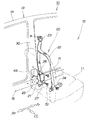
図1は本発明に係る車両を車室側から見た側面図であり、車両10の前部左側に運転席や助手席等の座席11を配置し、この座席11に着座した乗員の保護装置の一つであるシートベルト装置20を、左のセンタピラー30の近傍に配置したことを示す。センタピラー30は、車体13の前後方向中央でルーフ14を支える部材である。
【0019】
シートベルト装置20は、例えば、リトラクタ21に巻取られたシートベルト22を引出して、アッパアンカ23を通した後にロアアンカ24に取付けるようにしたものである。
【0020】
リトラクタ21は、センタピラー30の下部の車室15側に配置した一般的なベルト巻取り器であり、リトラクタケース25がセンタピラー30側、すなわち車幅方向外方へ膨出する構成である。センタピラー30は、膨出したリトラクタケース25を収納する収納孔43を有する。リトラクタケース25を収納孔43に収納し、リトラクタ21の上部26をセンタピラー30にボルト71で取付けるとともに、リトラクタ21の下部27をセンタピラー30にボルト72で取付けることで、リトラクタ21をセンタピラー30に装着することができる。
以下、センタピラー30に対するリトラクタ21の取付構造について詳しく説明する。
【0021】
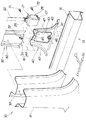
図2は本発明に係るセンタピラー並びにリトラクタの分解図である。このセンタピラー30は、車体前後方向に延びるサイドシル16から上方へ延びた部材であって、車体側面のアウトサイドパネル31と車室側のインナサイドパネル32とからなる閉断面体である。33は閉断面体の中に設けた補強材である。
【0022】
インナサイドパネル32は、サイドシル16に接合する下半部40と、その上の上半部50とに、上下二分割された上下二分割品である。これらの下半部40並びに上半部50は鋼板の折曲げ成形品である。上半部50の剛性は下半部40の剛性よりも小さくてすむ。その分だけ上半部50の板厚を下半部40の板厚よりも小さくした。。この結果、車体13の軽量化を図ることができる。
【0023】
このようなインナサイドパネル32の接合部分61は、下半部40の上端44と上半部50の下端51とを重ね合わせ、溶接にて接合することで一体化したものである。接合部分61の近傍にリトラクタ21を配置した。
【0024】
より詳しく説明すると、下半部40は、サイドシル16に接合する下部フランジ41と、下部フランジ41から上方へ延びる概ね平板状のパネル本体42とからなる。パネル本体42はその中央位置に、車幅方向に貫通した略矩形状の収納孔43を有する。収納孔43は、膨出したリトラクタケース25を収納する孔である。
【0025】
収納孔43は、上記図6に示す従来の孔のような上方に切欠かれた孔ではない。このため、上端44は車幅方向に繋がった形状である。さらにパネル本体42は、収納孔43の上方の上端44にボルト孔45を有するとともに、収納孔43の下方の背面にナット46を備える。47,47はフランジである。
一方、上半部50は概ね平板状部材であり、下端51の背面にナット52を備える。53,53はフランジである。
【0026】
本発明は、下半部40の上端44と上半部50の下端51との重ね合わせた部分、すなわち接合部分61で、下半部40の上端44と上半部50の下端51とリトラクタ21の上部26(フランジ上部26)とをボルト71で共締めし、下半部40のみにリトラクタ21の下部27(フランジ下部27)をボルト72で止めたことを特徴とする。
【0027】
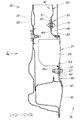
図3は本発明に係る左のセンタピラー並びにサイドシルの背面断面図であり、インナサイドパネル32にリトラクタ21を取付けた構成を示す。
この図は、リトラクタケース25を車室15側から収納孔43へ差込むことで、リトラクタケース25をセンタピラー30内に収納し、上半部50の下端51に下半部40の上端44を車室15側から重ね合わせ、その重ね合わせた部分に、さらにリトラクタ21のフランジ上部26を車室15側から重ね合わせ、その重ね合わせた部分で、下端51と上端44とフランジ上部26とをボルト71並びにナット52で共締めし、下半部40にリトラクタ21のフランジ下部27を車室15側から重ね合わせ、その重ね合わせた部分で、下半部40のみにフランジ下部27をボルト72で止めたことを示す。
【0028】
図4は図3の4矢視図であり、アウトサイドパネル並びに補強材を省略した状態のセンタピラー30並びにサイドシル16の構成を示す。
この図は、下半部40の上端44と上半部50の下端51とを重ね合わせて、スミ肉溶接やスポット溶接等の溶接によって接合したことを示す。下半部40の上端44と上半部50の下端51の各幅寸法L1は、上記図6に示す従来の上端105a並びに下端106aの各幅寸法L2と同じである。
【0029】
図5は図4の5−5線断面図であり、センタピラー30の断面構造、並びに、下半部40の上端44と上半部50の下端51とを重ね合わせた部分で、上端44と下端51とリトラクタ21のフランジ上部26とをボルト71並びにナット52で共締めした構成を示す。81はフロンロドア、82はリヤドア、83はピラーガーニッシュである。
【0030】
次に、上記構成のリトラクタ取付構造の作用を図4にて説明する。
センタピラー30のインナサイドパネル32として、下半部40と上半部50との上下二分割構造を採用した車両において、下半部40の上端44と上半部50の下端51とを重ね合わせて溶接等で接合し、更にこの重ね合わせた部分で下半部40の上端44と上半部50の下端51とリトラクタ21のフランジ上部26とをボルト71で共締めしたので、インナサイドパネル32にリトラクタ21のフランジ上部26を取付けるボルト71によって、下半部40の上端44と上半部50の下端51とをボルト接合することができる。
【0031】
下半部40の上端44と上半部50の下端51とを、溶接等による接合の他に、リトラクタ取付用ボルト71を利用して接合することができる。リトラクタ取付用ボルト71を締め付けるだけで、接合部分61の接合剛性を高めることができるので、接合剛性を高めるための新たな工数は発生しない。このように、車体の生産性を維持しつつ、接合部分61の接合剛性を容易に高めることができる。
【0032】
さらには、下半部40の上端44と上半部50の下端51とフランジ上部26とをボルト71で共締めするとともに、下半部40のみにリトラクタ21のフランジ下部27をボルト止めすることで、リトラクタ21を比較的剛性が大きい下半部40に直接取付けることができる。従って、センタピラー30にリトラクタ21を確実に取付けて安定した取付け状態を維持することができる。しかも、リトラクタ21からの荷重を高剛性の下半部40で確実に受け止めることができる。例えば、シートベルト装置20(図1参照)が作動したときであっても、リトラクタ21が揺れることなく安定した取付け状態で維持できる。
【0033】
なお、本発明は、左のセンタピラー30に対するリトラクタ21の取付構造に限定されるものではなく、右のセンタピラー30に対するリトラクタ21の取付構造にも適用できる。
また、上記実施の形態において、下半部40の上端44と上半部50の下端51との接合は溶接に限定されるものではなく、例えばリベット止めやボルト止めであってもよい。
さらにまた、センタピラー30は鋼板の折曲げ成形品に限定されるものではなく、例えばアルミニウム合金等の軽量合金製品であってもよい。
【0034】
【発明の効果】
本発明は上記構成により次の効果を発揮する。
請求項1は、下半部の上端と上半部の下端とを重ね合わせて溶接等で接合し、更にこの重ね合わせた部分で下半部の上端と上半部の下端とリトラクタの上部とをボルトで共締めしたので、インナサイドパネルにリトラクタの上部を取付けるボルトによって、下半部の上端と上半部の下端とをボルト接合することができる。
【0035】
下半部の上端と上半部の下端とを、従来の溶接等による接合の他に、リトラクタ取付用ボルトを利用して接合することができる。リトラクタ取付用ボルトを締め付けるだけで、接合部分の接合剛性を高めることができるので、接合剛性を高めるための新たな工数は発生しない。このように、車体の生産性を維持しつつ、接合部分の接合剛性を容易に高めることができる。
【0036】
さらには、下半部の上端と上半部の下端とリトラクタの上部とをボルトで共締めするとともに、下半部のみにリトラクタの下部をボルト止めすることで、リトラクタを比較的剛性が大きい下半部に直接取付けることができる。従って、センタピラーにリトラクタを確実に取付けて安定した取付け状態を維持することができる。しかも、リトラクタからの荷重を高剛性の下半部で確実に受け止めることができる。例えば、シートベルト装置が作動したときであっても、リトラクタが揺れることなく安定した取付け状態で維持できる。
【図面の簡単な説明】
【図1】本発明に係る車両を車室側から見た側面図
【図2】本発明に係るセンタピラー並びにリトラクタの分解図
【図3】本発明に係る左のセンタピラー並びにサイドシルの背面断面図
【図4】図3の4矢視図
【図5】図4の5−5線断面図
【図6】従来の車両用リトラクタ取付構造の概要図
【符号の説明】
10…車両、13…車体、14…ルーフ、15…車室、20…シートベルト装置、21…リトラクタ、22…シートベルト、25…リトラクタケース、26…リトラクタの上部(フランジ上部)、27…リトラクタの下部(フランジ下部)、30…センタピラー、31…アウトサイドパネル、32…インナサイドパネル、40…下半部、44…下半部の上端、50…上半部、51…上半部の下端、61…接合部分、71,72…ボルト。[0001]
BACKGROUND OF THE INVENTION
The present invention relates to a technique for improving a retractor mounting structure for a vehicle.
[0002]
[Prior art]
In recent years, a seat belt device has been developed as one of vehicle occupant protection devices. For example, in a seat belt device that protects a passenger seated in a driver seat or a passenger seat, a retractor (belt winder) is attached to the lower part of the center pillar of the vehicle body, and the seat belt is pulled out from the retractor for use. Yes. An example of a retractor mounting structure for the lower part of the center pillar will be described with reference to FIG.
[0003]
FIGS. 6A and 6B are schematic views of a conventional vehicle retractor mounting structure. FIG. 6A shows a side structure of the lower part of the
[0004]
The
[0005]
By the way, when the
The
[0006]
In order to reduce the weight, an
[0007]
Specifically, the
[0008]
As described above, the
[0009]
[Problems to be solved by the invention]
Incidentally, the
[0010]
The width L2 of the
[0011]
In order to secure the joint rigidity between the
Therefore, it is conceivable to increase the joining rigidity by another method while keeping the welding length as it is. However, if the number of joining steps increases, the productivity of the vehicle body decreases.
[0012]
Therefore, an object of the present invention is to adopt a vertically divided structure of the lower half and the upper half as the inner side panel of the center pillar so that the retractor is attached in the vicinity of the joint portion between the lower half and the upper half. An object of the present invention is to provide a technique that can easily increase the joint rigidity of the joint portion while maintaining the productivity of the vehicle body.
[0013]
[Means for Solving the Problems]
In order to achieve the above object, claim 1 is a center pillar that supports the roof at the center in the front-rear direction of the vehicle body, and the center pillar is composed of an outer panel on the side surface of the vehicle body and an inner side on the vehicle compartment side that is divided into two vertically. In a vehicle in which a retractor that winds up a seat belt is disposed in the vicinity of the joint portion between the upper end of the lower half and the lower end of the upper half of the inner side panel.
The joining part has a configuration in which the upper end of the lower half and the lower end of the upper half are overlapped and joined by welding or the like, and the upper end of the lower half, the lower end of the upper half, and the upper part of the retractor And a retractor mounting structure for a vehicle, wherein the lower part of the retractor is bolted only to the lower half.
[0014]
As the inner side panel of the center pillar, in a vehicle adopting a vertically divided structure of the lower half and the upper half, the upper end of the lower half and the lower end of the upper half are overlapped and joined by welding, etc. Since the upper end of the lower half, the lower end of the upper half, and the upper part of the retractor are fastened together with bolts in this overlapped area, the upper end and upper half of the lower half are secured by the bolts that attach the upper part of the retractor to the inner side panel. The lower end of the part can be bolted.
[0015]
The upper end of the lower half and the lower end of the upper half can be joined using a retractor mounting bolt in addition to joining by conventional welding or the like. By simply tightening the retractor mounting bolt, the joint rigidity of the joint portion can be increased, so that no new man-hours for increasing the joint rigidity are generated. In this way, it is possible to easily increase the joint rigidity of the joint portion while maintaining the productivity of the vehicle body.
[0016]
Furthermore, the upper end of the lower half, the lower end of the upper half, and the upper part of the retractor are fastened together with bolts, and the lower part of the retractor is bolted only to the lower half, so that the retractor has a relatively high rigidity. Can be installed directly on the half. Therefore, the retractor can be securely attached to the center pillar and the stable attachment state can be maintained. In addition, the load from the retractor can be reliably received by the lower half of the high rigidity. For example, even when the seat belt device is operated, the retractor can be maintained in a stable mounting state without shaking.
[0017]
DETAILED DESCRIPTION OF THE INVENTION
Embodiments of the present invention will be described below with reference to the accompanying drawings. “Front”, “Rear”, “Left”, “Right”, “Up”, “Down” follow the direction seen from the driver, Fr is front, Rr is rear, L is left, R is right CL indicates the vehicle width center (vehicle body center). The drawings are viewed in the direction of the reference numerals.
[0018]
FIG. 1 is a side view of a vehicle according to the present invention as viewed from the passenger compartment side. A
[0019]
The
[0020]
The
Hereinafter, the attachment structure of the
[0021]
FIG. 2 is an exploded view of the center pillar and the retractor according to the present invention. The
[0022]
The
[0023]
The joining
[0024]
More specifically, the
[0025]
The
On the other hand, the
[0026]
In the present invention, the
[0027]
FIG. 3 is a rear sectional view of the left center pillar and side sill according to the present invention, and shows a configuration in which the
In this figure, the
[0028]
4 is a view taken in the direction of
This figure shows that the
[0029]
5 is a cross-sectional view taken along line 5-5 of FIG. 4 and shows a cross-sectional structure of the
[0030]
Next, the operation of the retractor mounting structure having the above configuration will be described with reference to FIG.
In a vehicle adopting a vertically divided structure of the
[0031]
The
[0032]
Further, the
[0033]
The present invention is not limited to the attachment structure of the
Moreover, in the said embodiment, joining of the
Furthermore, the
[0034]
【The invention's effect】
The present invention exhibits the following effects by the above configuration.
In claim 1, the upper end of the lower half and the lower end of the upper half are overlapped and joined together by welding or the like, and further, the upper end of the lower half, the lower end of the upper half, and the upper part of the retractor Since the bolts are fastened together with bolts, the upper end of the lower half and the lower end of the upper half can be bolted together with the bolts that attach the upper part of the retractor to the inner side panel.
[0035]
The upper end of the lower half and the lower end of the upper half can be joined using a retractor mounting bolt in addition to joining by conventional welding or the like. By simply tightening the retractor mounting bolt, the joint rigidity of the joint portion can be increased, so that no new man-hours for increasing the joint rigidity are generated. In this way, it is possible to easily increase the joint rigidity of the joint portion while maintaining the productivity of the vehicle body.
[0036]
Furthermore, the upper end of the lower half, the lower end of the upper half, and the upper part of the retractor are fastened together with bolts, and the lower part of the retractor is bolted only to the lower half, so that the retractor has a relatively high rigidity. Can be installed directly on the half. Therefore, the retractor can be securely attached to the center pillar and the stable attachment state can be maintained. In addition, the load from the retractor can be reliably received by the lower half of the high rigidity. For example, even when the seat belt device is operated, the retractor can be maintained in a stable mounting state without shaking.
[Brief description of the drawings]
FIG. 1 is a side view of a vehicle according to the present invention as viewed from the passenger compartment side. FIG. 2 is an exploded view of a center pillar and a retractor according to the present invention. Fig. 4 is a view taken in the direction of
DESCRIPTION OF
Claims (1)
前記接合部分は、前記下半部の上端と前記上半部の下端とを重ね合わせて溶接等で接合した構成であり、この重ね合わせた部分で下半部の上端と上半部の下端と前記リトラクタの上部とをボルトで共締めし、前記下半部のみに前記リトラクタの下部をボルト止めしたことを特徴とする車両用リトラクタ取付構造。A center pillar that supports the roof at the center in the front-rear direction of the vehicle body, and the center pillar is a closed cross-sectional body that includes an outer panel on the side surface of the vehicle body and an inner side panel on the vehicle compartment side that is divided into upper and lower parts. In a vehicle in which a retractor that winds up a seat belt is disposed in the vicinity of the joint portion between the upper end of the lower half and the lower end of the upper half of the side panel.
The joining portion is configured such that the upper end of the lower half and the lower end of the upper half are overlapped and joined by welding or the like, and the upper end of the lower half and the lower end of the upper half are joined by this overlapped portion. A retractor mounting structure for a vehicle, wherein the upper part of the retractor is fastened together with a bolt, and the lower part of the retractor is bolted only to the lower half part.
Priority Applications (1)
| Application Number | Priority Date | Filing Date | Title |
|---|---|---|---|
| JP2002027463A JP3696554B2 (en) | 2002-02-04 | 2002-02-04 | Retractor mounting structure for vehicle |
Applications Claiming Priority (1)
| Application Number | Priority Date | Filing Date | Title |
|---|---|---|---|
| JP2002027463A JP3696554B2 (en) | 2002-02-04 | 2002-02-04 | Retractor mounting structure for vehicle |
Publications (2)
| Publication Number | Publication Date |
|---|---|
| JP2003226225A JP2003226225A (en) | 2003-08-12 |
| JP3696554B2 true JP3696554B2 (en) | 2005-09-21 |
Family
ID=27748971
Family Applications (1)
| Application Number | Title | Priority Date | Filing Date |
|---|---|---|---|
| JP2002027463A Expired - Fee Related JP3696554B2 (en) | 2002-02-04 | 2002-02-04 | Retractor mounting structure for vehicle |
Country Status (1)
| Country | Link |
|---|---|
| JP (1) | JP3696554B2 (en) |
Families Citing this family (10)
| Publication number | Priority date | Publication date | Assignee | Title |
|---|---|---|---|---|
| JP4563142B2 (en) * | 2004-10-29 | 2010-10-13 | タカタ株式会社 | Seat belt retractor, seat belt device, vehicle with seat belt device |
| JP2011088493A (en) * | 2009-10-20 | 2011-05-06 | Mazda Motor Corp | Vehicle body structure of vehicle |
| DE112011105786B4 (en) * | 2011-10-31 | 2016-08-18 | Toyota Jidosha Kabushiki Kaisha | pillar structure |
| JP6136233B2 (en) * | 2012-12-19 | 2017-05-31 | スズキ株式会社 | Vehicle body structure under the center pillar of the vehicle |
| JP2015089792A (en) * | 2013-11-07 | 2015-05-11 | トヨタ自動車株式会社 | Lower part structure of center pillar of vehicle |
| JP6350913B2 (en) * | 2014-08-11 | 2018-07-04 | スズキ株式会社 | Vehicle interior parts |
| JP6073279B2 (en) * | 2014-11-07 | 2017-02-01 | 本田技研工業株式会社 | Body side structure |
| JP6109134B2 (en) * | 2014-11-11 | 2017-04-05 | 本田技研工業株式会社 | Body side structure |
| JP7240648B1 (en) | 2021-12-09 | 2023-03-16 | いすゞ自動車株式会社 | vehicle panel structure |
| KR20230090729A (en) * | 2021-12-15 | 2023-06-22 | 현대자동차주식회사 | Seat belt mounting structure |
-
2002
- 2002-02-04 JP JP2002027463A patent/JP3696554B2/en not_active Expired - Fee Related
Also Published As
| Publication number | Publication date |
|---|---|
| JP2003226225A (en) | 2003-08-12 |
Similar Documents
| Publication | Publication Date | Title |
|---|---|---|
| US6568745B2 (en) | Automobile body structure | |
| JP3696554B2 (en) | Retractor mounting structure for vehicle | |
| JP5002624B2 (en) | Body structure with sliding door | |
| JP4314991B2 (en) | Car body rear structure | |
| JP3739976B2 (en) | Auto body structure | |
| JP2576887B2 (en) | Seat belt retractor mounting structure | |
| JP4337165B2 (en) | Car body structure | |
| JP2963578B2 (en) | Seat belt anchor mounting structure for vehicle | |
| WO2021060342A1 (en) | Vehicle floor structure | |
| JPS594822Y2 (en) | Automobile rear structure | |
| JP3132350B2 (en) | Reinforcement structure of seat belt anchorage | |
| JP4015094B2 (en) | Retractor mounting structure | |
| JPH11301524A (en) | Car body structure | |
| JP2001158325A (en) | Seatbelt anchor attaching structure | |
| JP4539269B2 (en) | Lower body structure of automobile | |
| JP2966679B2 (en) | Reinforcement structure for mounting part of seat belt retractor | |
| JPS6033080Y2 (en) | Mounting structure of automobile seat belt through anchor reinforcement | |
| JP3436088B2 (en) | Car rear body structure | |
| JPH06156316A (en) | Automobile rear body structure | |
| JP2003095130A (en) | Cross member connection structure of car | |
| JP2001012308A (en) | Fuel cylinder mounting structure for automobile with fuel cylinder | |
| JP3507013B2 (en) | Tether anchor mounting structure for child seat | |
| JP7430972B2 (en) | vehicle structure | |
| JPH0249170Y2 (en) | ||
| JP3979177B2 (en) | Truck cabin and carrier mounting structure |
Legal Events
| Date | Code | Title | Description |
|---|---|---|---|
| TRDD | Decision of grant or rejection written | ||
| A01 | Written decision to grant a patent or to grant a registration (utility model) |
Free format text: JAPANESE INTERMEDIATE CODE: A01 Effective date: 20050628 |
|
| A61 | First payment of annual fees (during grant procedure) |
Free format text: JAPANESE INTERMEDIATE CODE: A61 Effective date: 20050629 |
|
| R150 | Certificate of patent or registration of utility model |
Ref document number: 3696554 Country of ref document: JP Free format text: JAPANESE INTERMEDIATE CODE: R150 Free format text: JAPANESE INTERMEDIATE CODE: R150 |
|
| FPAY | Renewal fee payment (event date is renewal date of database) |
Free format text: PAYMENT UNTIL: 20080708 Year of fee payment: 3 |
|
| FPAY | Renewal fee payment (event date is renewal date of database) |
Free format text: PAYMENT UNTIL: 20090708 Year of fee payment: 4 |
|
| FPAY | Renewal fee payment (event date is renewal date of database) |
Free format text: PAYMENT UNTIL: 20100708 Year of fee payment: 5 |
|
| FPAY | Renewal fee payment (event date is renewal date of database) |
Free format text: PAYMENT UNTIL: 20100708 Year of fee payment: 5 |
|
| FPAY | Renewal fee payment (event date is renewal date of database) |
Free format text: PAYMENT UNTIL: 20110708 Year of fee payment: 6 |
|
| FPAY | Renewal fee payment (event date is renewal date of database) |
Free format text: PAYMENT UNTIL: 20110708 Year of fee payment: 6 |
|
| FPAY | Renewal fee payment (event date is renewal date of database) |
Free format text: PAYMENT UNTIL: 20120708 Year of fee payment: 7 |
|
| FPAY | Renewal fee payment (event date is renewal date of database) |
Free format text: PAYMENT UNTIL: 20120708 Year of fee payment: 7 |
|
| FPAY | Renewal fee payment (event date is renewal date of database) |
Free format text: PAYMENT UNTIL: 20130708 Year of fee payment: 8 |
|
| FPAY | Renewal fee payment (event date is renewal date of database) |
Free format text: PAYMENT UNTIL: 20140708 Year of fee payment: 9 |
|
| R250 | Receipt of annual fees |
Free format text: JAPANESE INTERMEDIATE CODE: R250 |
|
| LAPS | Cancellation because of no payment of annual fees |