JP3696132B2 - Active matrix substrate and manufacturing method thereof - Google Patents
Active matrix substrate and manufacturing method thereof Download PDFInfo
- Publication number
- JP3696132B2 JP3696132B2 JP2001208724A JP2001208724A JP3696132B2 JP 3696132 B2 JP3696132 B2 JP 3696132B2 JP 2001208724 A JP2001208724 A JP 2001208724A JP 2001208724 A JP2001208724 A JP 2001208724A JP 3696132 B2 JP3696132 B2 JP 3696132B2
- Authority
- JP
- Japan
- Prior art keywords
- substrate
- control member
- position control
- active element
- active
- Prior art date
- Legal status (The legal status is an assumption and is not a legal conclusion. Google has not performed a legal analysis and makes no representation as to the accuracy of the status listed.)
- Expired - Fee Related
Links
- 239000000758 substrate Substances 0.000 title claims description 178
- 239000011159 matrix material Substances 0.000 title claims description 48
- 238000004519 manufacturing process Methods 0.000 title claims description 27
- 238000012546 transfer Methods 0.000 claims description 95
- 239000000853 adhesive Substances 0.000 claims description 42
- 230000001070 adhesive effect Effects 0.000 claims description 42
- 238000000034 method Methods 0.000 claims description 39
- 238000005530 etching Methods 0.000 claims description 36
- 238000012545 processing Methods 0.000 claims description 9
- 238000005259 measurement Methods 0.000 claims 1
- CNQCVBJFEGMYDW-UHFFFAOYSA-N lawrencium atom Chemical compound [Lr] CNQCVBJFEGMYDW-UHFFFAOYSA-N 0.000 description 46
- 239000010408 film Substances 0.000 description 45
- 239000010410 layer Substances 0.000 description 44
- 230000015572 biosynthetic process Effects 0.000 description 20
- 239000004973 liquid crystal related substance Substances 0.000 description 12
- 239000000463 material Substances 0.000 description 12
- 239000003990 capacitor Substances 0.000 description 11
- 238000003860 storage Methods 0.000 description 11
- 239000011229 interlayer Substances 0.000 description 10
- 239000011521 glass Substances 0.000 description 8
- 238000000206 photolithography Methods 0.000 description 8
- 229910021420 polycrystalline silicon Inorganic materials 0.000 description 8
- 238000004544 sputter deposition Methods 0.000 description 7
- 238000001312 dry etching Methods 0.000 description 5
- 239000004033 plastic Substances 0.000 description 5
- 238000004528 spin coating Methods 0.000 description 5
- XUIMIQQOPSSXEZ-UHFFFAOYSA-N Silicon Chemical compound [Si] XUIMIQQOPSSXEZ-UHFFFAOYSA-N 0.000 description 4
- 239000012790 adhesive layer Substances 0.000 description 4
- 229910021417 amorphous silicon Inorganic materials 0.000 description 4
- 238000006073 displacement reaction Methods 0.000 description 4
- 230000001681 protective effect Effects 0.000 description 4
- 229910052710 silicon Inorganic materials 0.000 description 4
- 239000010703 silicon Substances 0.000 description 4
- VYPSYNLAJGMNEJ-UHFFFAOYSA-N silicon dioxide Inorganic materials O=[Si]=O VYPSYNLAJGMNEJ-UHFFFAOYSA-N 0.000 description 4
- 239000004925 Acrylic resin Substances 0.000 description 3
- 229920000178 Acrylic resin Polymers 0.000 description 3
- PNEYBMLMFCGWSK-UHFFFAOYSA-N aluminium oxide Inorganic materials [O-2].[O-2].[O-2].[Al+3].[Al+3] PNEYBMLMFCGWSK-UHFFFAOYSA-N 0.000 description 3
- 238000012986 modification Methods 0.000 description 3
- 230000004048 modification Effects 0.000 description 3
- 229920002120 photoresistant polymer Polymers 0.000 description 3
- 229910052814 silicon oxide Inorganic materials 0.000 description 3
- 238000001039 wet etching Methods 0.000 description 3
- KRHYYFGTRYWZRS-UHFFFAOYSA-N Fluorane Chemical compound F KRHYYFGTRYWZRS-UHFFFAOYSA-N 0.000 description 2
- YCKRFDGAMUMZLT-UHFFFAOYSA-N Fluorine atom Chemical compound [F] YCKRFDGAMUMZLT-UHFFFAOYSA-N 0.000 description 2
- PPBRXRYQALVLMV-UHFFFAOYSA-N Styrene Chemical compound C=CC1=CC=CC=C1 PPBRXRYQALVLMV-UHFFFAOYSA-N 0.000 description 2
- 239000003522 acrylic cement Substances 0.000 description 2
- 239000011248 coating agent Substances 0.000 description 2
- 238000000576 coating method Methods 0.000 description 2
- 238000007796 conventional method Methods 0.000 description 2
- 230000007423 decrease Effects 0.000 description 2
- 229910052731 fluorine Inorganic materials 0.000 description 2
- 239000011737 fluorine Substances 0.000 description 2
- 239000012535 impurity Substances 0.000 description 2
- 229910052751 metal Inorganic materials 0.000 description 2
- 239000002184 metal Substances 0.000 description 2
- 238000001020 plasma etching Methods 0.000 description 2
- 238000005498 polishing Methods 0.000 description 2
- 239000004743 Polypropylene Substances 0.000 description 1
- 229910004541 SiN Inorganic materials 0.000 description 1
- 229910004298 SiO 2 Inorganic materials 0.000 description 1
- BOTDANWDWHJENH-UHFFFAOYSA-N Tetraethyl orthosilicate Chemical compound CCO[Si](OCC)(OCC)OCC BOTDANWDWHJENH-UHFFFAOYSA-N 0.000 description 1
- 239000003513 alkali Substances 0.000 description 1
- 238000013459 approach Methods 0.000 description 1
- 239000004020 conductor Substances 0.000 description 1
- 229910021419 crystalline silicon Inorganic materials 0.000 description 1
- 230000000694 effects Effects 0.000 description 1
- 239000003822 epoxy resin Substances 0.000 description 1
- 239000011888 foil Substances 0.000 description 1
- 239000011810 insulating material Substances 0.000 description 1
- 150000002500 ions Chemical class 0.000 description 1
- 230000001678 irradiating effect Effects 0.000 description 1
- 238000002955 isolation Methods 0.000 description 1
- 238000005224 laser annealing Methods 0.000 description 1
- 239000007788 liquid Substances 0.000 description 1
- 239000011259 mixed solution Substances 0.000 description 1
- 239000011368 organic material Substances 0.000 description 1
- JMOHEPRYPIIZQU-UHFFFAOYSA-N oxygen(2-);tantalum(2+) Chemical compound [O-2].[Ta+2] JMOHEPRYPIIZQU-UHFFFAOYSA-N 0.000 description 1
- BPUBBGLMJRNUCC-UHFFFAOYSA-N oxygen(2-);tantalum(5+) Chemical compound [O-2].[O-2].[O-2].[O-2].[O-2].[Ta+5].[Ta+5] BPUBBGLMJRNUCC-UHFFFAOYSA-N 0.000 description 1
- 230000003071 parasitic effect Effects 0.000 description 1
- 238000000059 patterning Methods 0.000 description 1
- 238000005268 plasma chemical vapour deposition Methods 0.000 description 1
- 229920000647 polyepoxide Polymers 0.000 description 1
- 229920000642 polymer Polymers 0.000 description 1
- -1 polypropylene Polymers 0.000 description 1
- 229920001155 polypropylene Polymers 0.000 description 1
- 238000007639 printing Methods 0.000 description 1
- 239000010453 quartz Substances 0.000 description 1
- 230000007261 regionalization Effects 0.000 description 1
- 239000011347 resin Substances 0.000 description 1
- 229920005989 resin Polymers 0.000 description 1
- 238000007650 screen-printing Methods 0.000 description 1
- 238000007789 sealing Methods 0.000 description 1
- LIVNPJMFVYWSIS-UHFFFAOYSA-N silicon monoxide Chemical compound [Si-]#[O+] LIVNPJMFVYWSIS-UHFFFAOYSA-N 0.000 description 1
- HUAUNKAZQWMVFY-UHFFFAOYSA-M sodium;oxocalcium;hydroxide Chemical compound [OH-].[Na+].[Ca]=O HUAUNKAZQWMVFY-UHFFFAOYSA-M 0.000 description 1
- 239000000243 solution Substances 0.000 description 1
- 239000004094 surface-active agent Substances 0.000 description 1
- 229910001936 tantalum oxide Inorganic materials 0.000 description 1
- 229920001187 thermosetting polymer Polymers 0.000 description 1
- 239000010409 thin film Substances 0.000 description 1
- 238000007740 vapor deposition Methods 0.000 description 1
Images


Classifications
-
- H—ELECTRICITY
- H01—ELECTRIC ELEMENTS
- H01L—SEMICONDUCTOR DEVICES NOT COVERED BY CLASS H10
- H01L27/00—Devices consisting of a plurality of semiconductor or other solid-state components formed in or on a common substrate
- H01L27/02—Devices consisting of a plurality of semiconductor or other solid-state components formed in or on a common substrate including semiconductor components specially adapted for rectifying, oscillating, amplifying or switching and having potential barriers; including integrated passive circuit elements having potential barriers
- H01L27/12—Devices consisting of a plurality of semiconductor or other solid-state components formed in or on a common substrate including semiconductor components specially adapted for rectifying, oscillating, amplifying or switching and having potential barriers; including integrated passive circuit elements having potential barriers the substrate being other than a semiconductor body, e.g. an insulating body
- H01L27/1214—Devices consisting of a plurality of semiconductor or other solid-state components formed in or on a common substrate including semiconductor components specially adapted for rectifying, oscillating, amplifying or switching and having potential barriers; including integrated passive circuit elements having potential barriers the substrate being other than a semiconductor body, e.g. an insulating body comprising a plurality of TFTs formed on a non-semiconducting substrate, e.g. driving circuits for AMLCDs
- H01L27/1259—Multistep manufacturing methods
- H01L27/1262—Multistep manufacturing methods with a particular formation, treatment or coating of the substrate
- H01L27/1266—Multistep manufacturing methods with a particular formation, treatment or coating of the substrate the substrate on which the devices are formed not being the final device substrate, e.g. using a temporary substrate
-
- G—PHYSICS
- G02—OPTICS
- G02F—OPTICAL DEVICES OR ARRANGEMENTS FOR THE CONTROL OF LIGHT BY MODIFICATION OF THE OPTICAL PROPERTIES OF THE MEDIA OF THE ELEMENTS INVOLVED THEREIN; NON-LINEAR OPTICS; FREQUENCY-CHANGING OF LIGHT; OPTICAL LOGIC ELEMENTS; OPTICAL ANALOGUE/DIGITAL CONVERTERS
- G02F1/00—Devices or arrangements for the control of the intensity, colour, phase, polarisation or direction of light arriving from an independent light source, e.g. switching, gating or modulating; Non-linear optics
- G02F1/01—Devices or arrangements for the control of the intensity, colour, phase, polarisation or direction of light arriving from an independent light source, e.g. switching, gating or modulating; Non-linear optics for the control of the intensity, phase, polarisation or colour
- G02F1/13—Devices or arrangements for the control of the intensity, colour, phase, polarisation or direction of light arriving from an independent light source, e.g. switching, gating or modulating; Non-linear optics for the control of the intensity, phase, polarisation or colour based on liquid crystals, e.g. single liquid crystal display cells
- G02F1/133—Constructional arrangements; Operation of liquid crystal cells; Circuit arrangements
- G02F1/1333—Constructional arrangements; Manufacturing methods
-
- H—ELECTRICITY
- H01—ELECTRIC ELEMENTS
- H01L—SEMICONDUCTOR DEVICES NOT COVERED BY CLASS H10
- H01L24/00—Arrangements for connecting or disconnecting semiconductor or solid-state bodies; Methods or apparatus related thereto
- H01L24/80—Methods for connecting semiconductor or other solid state bodies using means for bonding being attached to, or being formed on, the surface to be connected
- H01L24/83—Methods for connecting semiconductor or other solid state bodies using means for bonding being attached to, or being formed on, the surface to be connected using a layer connector
-
- H—ELECTRICITY
- H01—ELECTRIC ELEMENTS
- H01L—SEMICONDUCTOR DEVICES NOT COVERED BY CLASS H10
- H01L27/00—Devices consisting of a plurality of semiconductor or other solid-state components formed in or on a common substrate
- H01L27/02—Devices consisting of a plurality of semiconductor or other solid-state components formed in or on a common substrate including semiconductor components specially adapted for rectifying, oscillating, amplifying or switching and having potential barriers; including integrated passive circuit elements having potential barriers
- H01L27/12—Devices consisting of a plurality of semiconductor or other solid-state components formed in or on a common substrate including semiconductor components specially adapted for rectifying, oscillating, amplifying or switching and having potential barriers; including integrated passive circuit elements having potential barriers the substrate being other than a semiconductor body, e.g. an insulating body
- H01L27/1214—Devices consisting of a plurality of semiconductor or other solid-state components formed in or on a common substrate including semiconductor components specially adapted for rectifying, oscillating, amplifying or switching and having potential barriers; including integrated passive circuit elements having potential barriers the substrate being other than a semiconductor body, e.g. an insulating body comprising a plurality of TFTs formed on a non-semiconducting substrate, e.g. driving circuits for AMLCDs
-
- G—PHYSICS
- G02—OPTICS
- G02F—OPTICAL DEVICES OR ARRANGEMENTS FOR THE CONTROL OF LIGHT BY MODIFICATION OF THE OPTICAL PROPERTIES OF THE MEDIA OF THE ELEMENTS INVOLVED THEREIN; NON-LINEAR OPTICS; FREQUENCY-CHANGING OF LIGHT; OPTICAL LOGIC ELEMENTS; OPTICAL ANALOGUE/DIGITAL CONVERTERS
- G02F1/00—Devices or arrangements for the control of the intensity, colour, phase, polarisation or direction of light arriving from an independent light source, e.g. switching, gating or modulating; Non-linear optics
- G02F1/01—Devices or arrangements for the control of the intensity, colour, phase, polarisation or direction of light arriving from an independent light source, e.g. switching, gating or modulating; Non-linear optics for the control of the intensity, phase, polarisation or colour
- G02F1/13—Devices or arrangements for the control of the intensity, colour, phase, polarisation or direction of light arriving from an independent light source, e.g. switching, gating or modulating; Non-linear optics for the control of the intensity, phase, polarisation or colour based on liquid crystals, e.g. single liquid crystal display cells
- G02F1/133—Constructional arrangements; Operation of liquid crystal cells; Circuit arrangements
- G02F1/136—Liquid crystal cells structurally associated with a semi-conducting layer or substrate, e.g. cells forming part of an integrated circuit
- G02F1/13613—Liquid crystal cells structurally associated with a semi-conducting layer or substrate, e.g. cells forming part of an integrated circuit the semiconductor element being formed on a first substrate and thereafter transferred to the final cell substrate
-
- H—ELECTRICITY
- H01—ELECTRIC ELEMENTS
- H01L—SEMICONDUCTOR DEVICES NOT COVERED BY CLASS H10
- H01L2221/00—Processes or apparatus adapted for the manufacture or treatment of semiconductor or solid state devices or of parts thereof covered by H01L21/00
- H01L2221/67—Apparatus for handling semiconductor or electric solid state devices during manufacture or treatment thereof; Apparatus for handling wafers during manufacture or treatment of semiconductor or electric solid state devices or components; Apparatus not specifically provided for elsewhere
- H01L2221/683—Apparatus for handling semiconductor or electric solid state devices during manufacture or treatment thereof; Apparatus for handling wafers during manufacture or treatment of semiconductor or electric solid state devices or components; Apparatus not specifically provided for elsewhere for supporting or gripping
- H01L2221/68304—Apparatus for handling semiconductor or electric solid state devices during manufacture or treatment thereof; Apparatus for handling wafers during manufacture or treatment of semiconductor or electric solid state devices or components; Apparatus not specifically provided for elsewhere for supporting or gripping using temporarily an auxiliary support
- H01L2221/68368—Apparatus for handling semiconductor or electric solid state devices during manufacture or treatment thereof; Apparatus for handling wafers during manufacture or treatment of semiconductor or electric solid state devices or components; Apparatus not specifically provided for elsewhere for supporting or gripping using temporarily an auxiliary support used in a transfer process involving at least two transfer steps, i.e. including an intermediate handle substrate
-
- H—ELECTRICITY
- H01—ELECTRIC ELEMENTS
- H01L—SEMICONDUCTOR DEVICES NOT COVERED BY CLASS H10
- H01L2224/00—Indexing scheme for arrangements for connecting or disconnecting semiconductor or solid-state bodies and methods related thereto as covered by H01L24/00
- H01L2224/01—Means for bonding being attached to, or being formed on, the surface to be connected, e.g. chip-to-package, die-attach, "first-level" interconnects; Manufacturing methods related thereto
- H01L2224/18—High density interconnect [HDI] connectors; Manufacturing methods related thereto
- H01L2224/23—Structure, shape, material or disposition of the high density interconnect connectors after the connecting process
- H01L2224/24—Structure, shape, material or disposition of the high density interconnect connectors after the connecting process of an individual high density interconnect connector
- H01L2224/241—Disposition
- H01L2224/24151—Connecting between a semiconductor or solid-state body and an item not being a semiconductor or solid-state body, e.g. chip-to-substrate, chip-to-passive
- H01L2224/24221—Connecting between a semiconductor or solid-state body and an item not being a semiconductor or solid-state body, e.g. chip-to-substrate, chip-to-passive the body and the item being stacked
- H01L2224/24225—Connecting between a semiconductor or solid-state body and an item not being a semiconductor or solid-state body, e.g. chip-to-substrate, chip-to-passive the body and the item being stacked the item being non-metallic, e.g. insulating substrate with or without metallisation
- H01L2224/24226—Connecting between a semiconductor or solid-state body and an item not being a semiconductor or solid-state body, e.g. chip-to-substrate, chip-to-passive the body and the item being stacked the item being non-metallic, e.g. insulating substrate with or without metallisation the HDI interconnect connecting to the same level of the item at which the semiconductor or solid-state body is mounted, e.g. the item being planar
-
- H—ELECTRICITY
- H01—ELECTRIC ELEMENTS
- H01L—SEMICONDUCTOR DEVICES NOT COVERED BY CLASS H10
- H01L2924/00—Indexing scheme for arrangements or methods for connecting or disconnecting semiconductor or solid-state bodies as covered by H01L24/00
- H01L2924/01—Chemical elements
- H01L2924/01055—Cesium [Cs]
-
- H—ELECTRICITY
- H01—ELECTRIC ELEMENTS
- H01L—SEMICONDUCTOR DEVICES NOT COVERED BY CLASS H10
- H01L2924/00—Indexing scheme for arrangements or methods for connecting or disconnecting semiconductor or solid-state bodies as covered by H01L24/00
- H01L2924/15—Details of package parts other than the semiconductor or other solid state devices to be connected
- H01L2924/151—Die mounting substrate
- H01L2924/1515—Shape
- H01L2924/15153—Shape the die mounting substrate comprising a recess for hosting the device
Landscapes
- Engineering & Computer Science (AREA)
- Power Engineering (AREA)
- Physics & Mathematics (AREA)
- Microelectronics & Electronic Packaging (AREA)
- Computer Hardware Design (AREA)
- General Physics & Mathematics (AREA)
- Condensed Matter Physics & Semiconductors (AREA)
- Nonlinear Science (AREA)
- Manufacturing & Machinery (AREA)
- Devices For Indicating Variable Information By Combining Individual Elements (AREA)
- Liquid Crystal (AREA)
- Optics & Photonics (AREA)
- Crystallography & Structural Chemistry (AREA)
- Chemical & Material Sciences (AREA)
- Mathematical Physics (AREA)
- Thin Film Transistor (AREA)
Description
【0001】
【発明の属する技術分野】
本発明は、アクティブマトリクス基板及びその製造方法に関する。
【0002】
【従来の技術】
液晶ディスプレイ(LCD)は、ノート型パソコンやテレビ、携帯電話や携帯情報端末(PDA)などのモバイル情報機器の表示端末として広く用いられている。例えば、アクティブマトリクス型LCDは、ガラス基板上に、アモルファスシリコンや多結晶シリコンを活性層とした薄膜トランジスタ(TFT)をマトリクス状に形成し、対向ガラス基板と5μm程度のギャップを設けて固定し、その間に液晶を注入して、高画質なフルカラー表示の得られる薄型の表示装置として利用されている。一方で、LCDへのさらなる要求として、低消費電力、多画素数、大型化、軽量化、低コスト化、高表示品位等がある。
【0003】
しかしながら、TFTのようなアクティブ素子は、ガラス基板上にCVD、スパッタ等の真空プロセスによって電極、絶縁膜などを成膜し、これらをフォトリソグラフィおよびドライエッチングあるいはウェットエッチングすることによりパターン形成を行なうという工程を繰り返す。従って、大きな表示装置を得るためには、真空プロセスの装置を大きくする必要があり、大きなコストがかかるという問題がある。特に、表示装置の中で、アクティブ素子が占める面積の割合は小さいため、大きな真空プロセスの装置を用いるのは無駄が多い。
【0004】
また、軽量化の手段として、プラスチック基板やフィルム基板上に形成したTFTを用いることが検討されているが、これらの基板へのTFT形成は、プロセス温度を低下することが必要である。しかしながら、プロセス温度の低下によりTFT性能が劣化して、画質、画素数等に制限が出ることが考えられる。さらに、これらの基板は熱膨張係数が大きく、塑性変形する温度も低いために、高精細化が不可能であることも予想され、表示品位の低下につながるために問題となっている。
【0005】
これらの問題を解決する方法として、TFT等のアクティブ素子を、ガラスやシリコン等からなる素子形成基板に形成後、プラスチックやフィルム等からなる別の転写先基板に選択的に転写して、アクティブ素子間を別途形成した配線で接続する方法が、特開2001−7340号公報等に示されている。
【0006】
図27に、特開2001−7340号公報に記載のアクティブ素子を転写して形成する方法の1工程を示す。この方法では、TFT等のアクティブ素子2701を素子形成基板(図示せず)上に形成して、中間転写基板2702に転写してから、さらに中間転写基板2702上のアクティブ素子2701を転写先基板2703に転写するものである。
【0007】
この方法では、アクティブ素子2701と中間転写基板2702とは、接着・剥離層2704を介して接着されている。接着・剥離層2704は、接着力を有し、光や熱を照射されることにより接着力が低下する物質を用いている。そして、図27に示すように、転写先基板2703上の、アクティブ素子2701を転写したい領域には接着層2705を形成しておき、アクティブ素子2701を接着層2705に押付けながら、マスク2706を介して転写したいアクティブ素子2701のみに光または熱を照射して、アクティブ素子2701の転写を行なう。
【0008】
特開2001−7340号公報に記載の方法では、アクティブ素子を転写することが可能であり、素子形成基板で高密度にアクティブ素子を形成して、転写先基板に選択的に転写可能である為、効率がよい。しかしながら、この方法では、転写先基板の面内でアクティブ素子の位置が規定されておらず、自由度があるために、中間転写基板と転写先基板の位置あわせのアライメントの精度が位置精度となる。従って、複数回の転写で転写先基板を作製する場合、アクティブ素子の位置ずれが生じ、この位置ずれのばらつきも生じてしまう。従って、アクティブ素子の転写工程の後に配線を行なうと、位置ずれによってアクティブ素子と配線や電極との寄生容量にばらつきが生じて表示品位の低下が生じる。
【0009】
また、アクティブ素子を転写する際の位置精度を上げるために、転写先基板にテーパー形状のくぼみを設け、同じテーパー形状に加工したアクティブ素子を転写先基板に転写する方法もある。
【0010】
この方法では、アクティブ素子及び転写先基板がテーパー形状を有することからアクティブ素子がこのテーパー形状に合わせて入り込み、位置精度の高い転写を行なう事が出来る。しかしながら、この転写方法では、転写先基板の凹部にアクティブ素子を押し込んで転写するために、密に形成されたアクティブ素子を選択的に転写先基板に転写することは出来ない。
【0011】
【発明が解決しようとする課題】
上述したように、アクティブ素子を転写してアクティブマトリクス基板を形成する、従来の方法では、位置精度の高い、選択的な転写を行なうことが出来なかった。
【0012】
そこで本発明は、位置精度の高い、選択的な転写を行なうことの可能な、アクティブマトリクス基板及びその製造方法を提供することを目的とする。
【0013】
【課題を解決するための手段】
そこで本発明は、基板と、この基板上に、その内側に所定空間を形成するように配置され、かつその内側側面が傾斜している位置制御部材と、所定空間に適合するように配置され、かつその外形側面として位置制御部材の内側側面とほぼ同じである傾斜した側面を少なくとも一部に有するアクティブ素子と、このアクティブ素子を基板または位置制御部材と接着する接着部と、を具備し、位置制御部材は接着部に対して濡れ性を低くしたことを特徴とするアクティブマトリクス基板を提供する。
【0014】
本発明においては、濡れ性の測定を、位置制御部材と接着部との接触角の大きさを測定することによって行い、この接触角を70°以上としても良い。
【0015】
また本発明においては、アクティブ素子の下面にエッチングストッパー層を設けても良い。
【0016】
また本発明においては、位置制御部材は、その側面に少なくとも1つの切れ目または穴を有しても良い。
【0017】
また本発明においては、位置制御部材は、その側面につながる底部を有しても良い。
【0018】
また本発明においては、アクティブ素子の形状が回転対称性を持たなくても良い。
【0019】
また本発明においては、アクティブ素子及び位置制御部材の、傾斜した側面を同一としても良い。
【0020】
また本発明においては、基板面からアクティブ素子上面までの高さが、基板面から位置制御部材上面までの高さ以上であっても良い。
【0021】
また本発明においては、基板面から位置制御部材上面までの高さが0.3μm以上5μm以下であっても良い。
【0022】
また本発明は、第1の基板上にアクティブ素子を形成する素子形成工程と、アクティブ素子を第2の基板に転写する第1の転写工程と、アクティブ素子がその外形側面に傾斜を有するよう加工する素子加工工程と、第3の基板上に、内側に所定空間を形成するように配置され、かつその内側側面が傾斜を有する位置制御部材を形成する位置制御部材形成工程と、位置制御部材の内側に接着部を形成する接着部形成工程と、素子加工工程及び接着部形成工程の後にアクティブ素子と位置制御部材とを位置あわせしてアクティブ素子を接着部に接着させる第2の転写工程と、を具備し、位置制御部材は接着部に対して濡れ性を低くしたことを特徴とするアクティブマトリクス基板の製造方法を提供する。
【0023】
【発明の実施の形態】
以下に、本発明の実施形態を図面を参照しつつ詳細に説明するが、本発明はこれらの実施形態に限定されるものではない。
【0024】
(第1の実施形態)
まず、本発明の第1の実施形態について説明する。本実施形態は、アクティブ素子を素子形成基板(第1の基板)に形成し、これを中間転写基板(第2の基板)に転写した後テーパー形状に加工する。そして、転写先基板(第3の基板)にもテーパー形状を有する位置制御部材を形成し、これとアクティブ素子とを位置あわせして転写して、アクティブマトリクス基板とするものである。
【0025】
まず本実施形態のアクティブマトリクス基板の構成を、図15を用いて説明する。
【0026】
図15に示すように、本実施形態のアクティブマトリクス基板は、転写先基板107上に基板面と垂直な方向の内側断面が傾斜したテーパー形状を有するアクティブ素子103と、アクティブ素子103を囲むように内側側面がテーパー形状を有する位置制御部材108を具備する。アクティブ素子103は下面にエッチングストッパー層102を有し、これは接着部109を介して転写先基板107に接着されている。これらの上には、全面に転写後層間絶縁膜111が設けられ、転写後層間絶縁膜111の、アクティブ素子103の電極に対応する領域にはコンタクト部が設けられ、配線112や画素電極113が形成されている。本実施形態では、エッチングストッパー層102をアクティブ素子103と別に図示しているが、エッチングストッパー層102を含めてアクティブ素子103と呼ぶ場合もある。
【0027】
本実施形態のアクティブマトリクス基板の製造方法を、図1から図15を用いて説明する。
【0028】
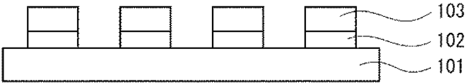
まず、図1に示すように、シリコン、無アルカリガラス、石英等からなる素子形成基板101上に、タンタル酸化物(TaOx)、アルミナ(AlOx)、シリコン酸化膜(SiOx)等の絶縁材料を用いて、約0.1〜10μmの厚さのエッチングストッパー層102を形成する。本実施形態では、後述するように、素子形成基板101は、研磨・エッチングを行うことにより除去する。従って、エッチングストッパー層102の材料としては、素子形成基板101に対してエッチング選択比の大きい材料を用いることが望ましい。
【0029】
エッチングストッパー層102の上には、複数のアクティブ素子103を形成する。各アクティブ素子103は、多結晶シリコンTFTやこれを含む回路、アモルファスシリコンTFTやこれを含む回路、又は結晶シリコンTFTやこれを含む回路等を形成すればよく、限定されるものではない。アクティブ素子103の寸法はその一辺の長さを約20〜100μmとし、厚さを約1〜5μm、素子間隔を約3〜20μmとすることが好ましい。本実施形態では、エッチングストッパー層102の厚さを約1μm、アクティブ素子103の素子寸法を約36μmの正方形、隣接する素子間隔は約6μm、素子配置のピッチは約42μmとする。
【0030】
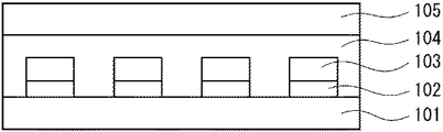
次に、図2に示すように、エッチングストッパー層102をアクティブ素子103毎に分離する。エッチングストッパー層102の加工は、フォトリソグラフィを用いてレジスト(図示せず)をアクティブ素子103の形状にパターニングした後、レジストをマスクとしてエッチングすることにより行う。エッチングとしては、リアクティブイオンエッチング(RIE)等を用いて行う。エッチングストッパー層102の分離は、後述の素子形成基板101の除去後に行っても良い。
【0031】
次に、図3に示すように、ガラス若しくはプラスチック等からなる中間転写基板105を用意する。素子形成基板101のアクティブ素子103を形成した面と、中間転写基板105との間に、接着・剥離層104を挟み、貼り合わせる。接着・剥離層104としては、ベンゾフェロンを含むアクリル系接着剤など、接着力を有し、紫外光などにより剥離が促進される材料を選べばよい。このような接着・剥離層104を中間転写基板105に塗布して素子形成基板101と密着させ、接着する。本実施形態においては、接着・剥離層104の膜厚を約4μmとする。
【0032】
次に、図4に示すように、素子形成基板101を除去する。例えば、素子形成基板101としてガラス基板を用いた場合には、機械研磨により素子形成基板101を薄くした後、フッ酸と界面活性剤の混合液等でエッチングする。エッチングは、エッチングストッパー層102で停止するよう、エッチングストッパー層102の材料や膜質、エッチング液の材料を選択する。
【0033】
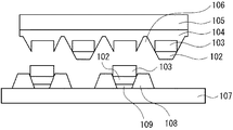
次に、図5に示すように、各アクティブ素子103とエッチングストッパー層102、それから接着・剥離層104をエッチングすることにより、所定の角度を持った切込み106を入れ、テーパー形状にする。アクティブ素子103の周囲の接着・剥離層104はテーパー形状とせずに、夫々のアクティブ素子103が完全に分離されるように、アクティブ素子103の周囲の接着・剥離層104を全てエッチングしても良い。エッチングの方法としては、ドライエッチング、ウェットエッチング等を用いればよく、等方エッチング条件を用いることでテーパー形状を得ることが出来る。テーパー角(切込み面がエッチングストッパー層の下面となす角度)としては、約30度以上約85度以下であることが好ましい。約30度未満では、後述する転写工程でアクティブ素子の位置がずれた状態で押し付けられた際にアクティブ素子が動きにくくなり、所望の位置に入りにくくなる。約85度より大きいと、後述する転写工程で、アクティブ素子の位置のずれの許容量が小さくなりすぎる。エッチングストッパー層102を、テーパー形状を有するようエッチングする条件と、接着・剥離層104をテーパー形状もしくはテーパー形状以外にエッチングする条件とは、異なっても良い。また、接着・剥離層104をテーパー形状とした場合でも、アクティブ素子103及びエッチングストッパー層102のテーパー形状と接着・剥離層104のテーパー形状は異なっても良い。
【0034】
本実施形態では、図6に示すように、テーパー角を約45度、エッチングストッパー層102での切込み106の最大幅を約8μmとする。これにより、エッチングされたエッチングストッパー層102残存部の下面の幅は約34μmとなる。
【0035】
他方、図7に示すように、無アルカリガラス基板、ソーダライム基板、プラスチック基板若しくは金属箔基板等を用いた転写先基板107の、アクティブ素子(エッチングストッパー層を含む)を転写する部分に、位置制御部材108を形成しておく。位置制御部材108は、アクティブ素子が転写された際にアクティブ素子を囲み、アクティブ素子に接する内側側面が傾斜したテーパー形状となるよう形成する。位置制御部材108としては、本実施形態では感光性アクリル樹脂を、約2μmの膜厚となるよう塗布し、フォトリソグラフィによってパターニングする。位置制御部材108の材料としてはこれに限られるものではなく、後述する、接着剤を用いた接着部との濡れ性が低ければよい。例えば、位置制御部材108として、通常用いられる接着剤との濡れ性の低いシリコン樹脂やスチレン、ポリプロピレン、フッ素系ポリマー等の有機材料をスピンコート法等により形成しても良い。また、SiO2やタンタル酸化物、アルミナ等の酸化物やSiNx等をスパッタ法や蒸着法、スピンコート法等で形成した後、これにシリコンコートやフッ素コートを行うことにより濡れ性を下げても良い。また、接着部を形成する部分には、プライマー処理を行うことにより濡れ性を上げ、ここに接着部が選択的に形成されるようにしても良い。
【0036】
ここで位置制御部材108と接着部との濡れ性とは、これらの間の付着の程度を示す。これらの間の濡れ性が低いと、傾斜などがある場合、接着部は下方へ流れやすく同じ位置に留まりにくい。ある部材の上に接着部を置いた場合、付着張力等により接着部の表面の接触角が大きい時は、これらの間の濡れ性は低い。従って濡れ性、つまり付着の程度を測定する際は、例えば位置制御部材108に対する接着部の接触角を測定すればよい。濡れ性、つまり付着の程度が小さい時には、これらの間の接触角は大きい。位置制御部材108に対する接着部の濡れ性を低くするには、これらの間の接触角は、約70°以上であれば好ましく、さらに好ましくは約90°以上である。この様に、位置制御部材108と接着部との接触角が大きく濡れ性が低いことにより、接着部が位置制御部材108のテーパー部に付いたとしても、好ましい位置に流れてゆく。転写先基板107と接着部との濡れ性は、位置制御部材108と接着部との濡れ性よりも高い方が、接着部が安定に保持されるために好ましい。本実施形態における位置制御部材108と接着部との接触角は約140°であった。
【0037】
また、転写先基板107面から位置制御部材108上面までの高さは、約0.3μm以上約10μm以下であることが好ましい。これは約0.3μmより低いとアクティブ素子が位置制御部材を越えて動いてしまい、アクティブ素子の位置制御ができなくなる為である。また、約10μmより高いと位置制御部材の大きさが大きくなりすぎ、表示素子の精細度が低くなってしまうであるためである。本実施形態では、転写先基板107面から位置制御部材108上面までの高さを約2μmとしている。また、アクティブ素子を接着層に良好に接着する為に、転写先基板107面からアクティブ素子上面までの高さは位置制御部材上面までの高さ以上とすることが好ましい。
【0038】
また、位置制御部材108がアクティブ素子に接する内側側面のテーパー角は、アクティブ素子に与えたテーパー角とほぼ同じ、すなわち約30度以上約85度以下であることが好ましい。約30度未満では、後述する転写工程で、アクティブ素子の位置がずれた状態で押し付けられた際にアクティブ素子が動きにくくなり、所望の位置に入りにくくなる。約85度より大きいと後述する転写工程での、アクティブ素子の位置のずれの許容量が小さくなりすぎる。本実施形態では、エッチングストッパー層102及びアクティブ素子103のテーパー形状と位置制御部材108のテーパー形状とを合致させるために、テーパー角を約45度とする。
【0039】
次に、図8に示すように、位置制御部材108の内側に、スクリーン印刷法や滴下法等により接着部109を形成する。接着部109としては、紫外線硬化接着剤、エポキシ樹脂、熱硬化接着剤及びアクリル接着剤等の液体状の接着剤を用いれば良い。この時、接着部109の高さは、位置制御部材108の高さより高くならないように調整する。本実施形態では、接着部109の高さを約1μmとする。位置制御部材108及び接着部109を上から見た平面図を図10に示す。
【0040】
接着部109を形成する際、素子サイズが小さい場合などに、図9に示すように接着部109が少しずれて、位置制御部材108の側部に形成される可能性がある。しかし、本実施形態では、接着部109との濡れ性が低い材料を用いてテーパー形状を有する位置制御部材108を形成しているので、接着部109がこのような位置に形成されても、適正な位置にずれていく。
【0041】
次に、図11に示すように、中間転写基板105上のアクティブ素子103と転写先基板107上の位置制御部材108とを位置合わせする。
【0042】
次に、図12に示すように、中間転写基板105と転写先基板107との間に適度の圧力を印加しながら、中間転写基板105側からマスク110を介して、転写したいアクティブ素子103に、選択的に紫外光を照射する。紫外光を照射されることにより、選択されたアクティブ素子103に対応する領域の接着・剥離層104の接着力が低下する。そして、同時に転写先基板107側からも紫外光を照射し、接着部109を硬化させてアクティブ素子103と転写先基板107とを接着する。このとき、位置制御部材108とアクティブ素子103は、テーパー形状であることから、アクティブ素子103の位置が転写したい位置からずれていたとしても、中間転写基板105と転写先基板107との間に圧力が印加されると、アクティブ素子103は適切な位置にずれる。本実施形態では、位置制御部材108とアクティブ素子103のテーパー形状を同一のものとしている為、アクティブ素子103の位置精度が高くなり好ましいが、これらのテーパー形状は、同一でなくとも、アクティブ素子103の位置精度を上げることは可能である。また、位置制御部材108は転写先基板107上に凸状に形成されていることから、転写したいアクティブ素子103のみが転写先基板107に近づき、その他のアクティブ素子はダメージを受けることなく安定に中間転写基板105に保持される。
【0043】
なお、本実施形態では、中間転写基板105側からは、マスク110を介して選択的に、アクティブ素子103に紫外光を照射しているが、紫外領域のレーザー光をスキャンすることにより選択的な紫外光の照射を行っても良い。
【0044】
このように、接着・剥離層104の接着力を低下させ、接着部109の接着力を生じさせた状態で、中間転写基板105と転写先基板107との間に加えていた圧力を解放し、両基板を離すことにより、図13に示すように、選択したアクティブ素子103のみが転写先基板107に転写される。
【0045】
次に、図14に示すように、アクティブ素子103を転写した転写先基板107上に転写後層間絶縁膜111を形成する。転写後層間絶縁膜111の材料としては、感光性アクリル樹脂などを用いればよく、約1〜50μmの膜厚とすれば良い。転写後層間絶縁膜111は、アクティブ素子103のコンタクトを取る必要がある領域に、フォトリソグラフィを用いてコンタクトホールを開口する。
【0046】
次に、図15に示すように、金属やITO等の導電性材料をスパッタもしくは印刷することにより、信号線や走査線等の配線112や画素電極113を形成し、本実施形態のアクティブマトリクス基板を完成する。これらの配線112や画素電極113は別の材料を用いて、別の工程で形成してもよいし、複数の層に配線を形成しても良い。
【0047】
このように、本実施形態では、位置制御部材108及びアクティブ素子103がテーパー形状を有することにより、位置精度の高いアクティブマトリクス基板を形成することが出来る。また、位置制御部材108は転写先基板107上に凸状に形成されていることから、中間転写基板105上のアクティブ素子103は、選択的に転写先基板107に転写することが出来、その他のアクティブ素子103は、ダメージを受けることなく安定に中間転写基板107上に保持される。
さらに、位置制御部材108として、接着部109との濡れ性が低い材料を用いているので、接着部109が適正な位置に流れてゆき形成されるために、アクティブ素子103は安定に接着され、好ましい。
【0048】
(第2の実施形態)
次に、本発明の第2の実施形態について説明する。本実施形態は、位置制御部材の形状が第1の実施形態とは異なるものである。本実施形態の説明は、第1の実施形態と異なる点を中心に行い、第1の実施形態と同様な点については、説明を省略する。
【0049】
本実施形態のアクティブマトリクス基板を図19に示す。図19では、アクティブ素子より上の構成は第1の実施形態と同様とすればよく省略する。本実施形態のアクティブマトリクス基板は、転写先基板107上に、基板面と垂直な方向の内側断面が傾斜したテーパー形状を有する位置制御部材203と、これに囲まれるように傾斜したテーパー形状を有するアクティブ素子103が形成される点は第1の実施形態と同様である。しかし、位置制御部材203は、アクティブ素子103の側部だけでなく、下面も覆う形状となっている点が第1の実施形態と異なる。アクティブ素子103は、接着部109を介して位置制御部材203に接着されている。
【0050】
本実施形態の位置制御部材203の製造方法を図16から図18を用いて説明する。その他の部分の製造方法は、第1の実施形態と同様にして行えばよく、説明を省略する。
【0051】
まず、図16に示すように、転写先基板107上に、位置制御部材用パターン201を、アクティブ素子を転写する領域及びその周辺に形成する。位置制御部材用パターン201の材料としては感光性アクリル樹脂を用い、約5μmの膜厚となるよう全面に塗布し、フォトリソグラフィによりパターニングする。
【0052】
次に、図17に示すように、位置制御部材用パターン201のアクティブ素子が転写される領域を開口部とした、フォトレジスト202のパターンを形成する。
【0053】
次に、図18に示すように、位置制御部材用パターン201の、アクティブ素子が転写される領域をエッチングして周囲より薄くしてフォトレジスト202を除去し、位置制御部材203を完成する。このとき、位置制御部材用パターン201の加工は、等方的なドライエッチングやウェットエッチング等の方法を用い、アクティブ素子に接する内側側面がテーパー形状を有するように行えば良い。
本実施形態では、転写先基板107面からアクティブ素子の下面と接する領域の位置制御部材203上面までの高さを、約2μmとし、周囲の高さを約5μmとする。また、テーパー角は約45度とする。
【0054】
本実施形態においても、位置制御部材203及びアクティブ素子103がテーパー形状を有することにより、選択的なアクティブ素子103の転写が可能で、位置精度の高いアクティブマトリクス基板を形成することが出来る。また、本実施形態においては、接着部109との濡れ性の低い位置制御部材203が、アクティブ素子103の側面だけでなく下面も覆っていることから接着部109が流れやすく適正な位置に形成されやすい。さらに、位置制御部材203により、アクティブ素子103の接着面が高くなることから、転写を行わないアクティブ素子103が転写先基板107などに接触することによるダメージ等が低減される。
【0055】
図20及び図21は、位置制御部材の変形例を示す平面図である。例えば位置制御部材301は、図20に示すように、アクティブ素子(図示せず)と接着する接着部109の周囲を、切れ目を持って囲んでも良い。また、図21に示すように、位置制御部材401が、アクティブ素子(図示せず)と接着する接着部109の周囲を、複数の切れ目を持って囲んでも良い。これらのように、位置制御部材が切れ目を持ってアクティブ素子を囲んでも、これらがテーパー形状を有することにより、アクティブ素子を選択的に、位置精度高く転写することが出来る。切れ目を持った位置制御部材を用いることにより、接着部の量が多かった場合でも、この切れ目を通って接着部が逃げるので好ましい。切れ目を持った位置制御部材を用いる場合には、必要な接着部まで流れてしまわないよう、粘性の高い接着部を用いることが好ましい。これらの位置制御部材は、第1の実施形態のようにアクティブ素子の側面のみを囲む形状でもよいし、第2の実施形態のようにアクティブ素子の側面及び下面を囲む形状としても良い。また、これらのアクティブ素子や位置制御部材の形状、及びテーパー形状は、回転対称性を持たないことが好ましい。これらが回転対称性を持たないことにより、アクティブ素子の転写の際に、転写角度が多少ずれた場合でも、異なる向きに転写されることを防ぐことが可能となる。
【0056】
(第3の実施形態)
次に、本発明の第3の実施形態について説明する。本実施形態では、TFT及び蓄積容量をアクティブ素子として素子形成基板に形成し、中間基板にこれを転写した後、アクティブ素子がテーパー形状を有するよう加工する。そして、テーパー形状を有する位置制御部材を形成した転写先基板に転写し、配線等を形成してアクティブマトリクス基板とすることにより液晶表示装置を形成するものである。
【0057】
図24は、本実施形態の液晶表示装置の一部を示す断面図である。本実施形態の液晶表示装置の1画素は、信号線501、走査線502、TFT503、蓄積容量504及び画素電極505を有する。本実施形態ではTFT503及び蓄積容量504をアクティブ素子103としている。TFT503のゲートはオフリーク電流を低減する為にダブルゲート構造として走査線502に接続し、ソース又はドレインの一方は信号線501に、他方は画素電極505に接続する。蓄積容量504は、画素電極505と隣の走査線502との間で容量を持つ、ゲートオーバーラップCs構造としている。
【0058】
この画素において液晶に電圧を印加する場合には、走査線502のパルスにより、所定のタイミングでTFT503をON状態とし、信号線501からの画像信号を画素電極505に印加することにより行う。この画素電極505とOFF状態である隣の走査線502との間には蓄積容量504が介在し、電荷を保持することが出来る。
【0059】
次に、本実施形態のアクティブ素子の製造方法を、素子平面図である図22、及び図22のA−A´間の素子断面図である図23を用いて説明する。
【0060】
まず、素子形成基板506上に、アルミナなどを用いて、約100nmの膜厚となるようエッチングストッパー層507を形成する。
【0061】
エッチングストッパー層507上には、アモルファスシリコンを約50nmの膜厚となるようCVD法により全面に堆積する。このアモルファスシリコンをエキシマレーザーアニール法で結晶化させることにより、多結晶シリコン膜508とする。この多結晶シリコン膜508をフォトリソグラフィで加工して島状とし、TFT503の活性層及び蓄積容量504の下部電極とする。多結晶シリコン膜508には、p型の不純物をドーピングする。
【0062】
次に、シリコン酸化膜を約100nmの膜厚となるよう全面にプラズマTEOS法で形成し、ゲート絶縁膜509とする。
【0063】
ゲート絶縁膜509上には、MoWを約300nmの膜厚となるように全面にスパッタ法で形成し、フォトリソグラフィによりパターニングすることにより、TFT503のゲート電極510を形成する。このゲート電極510は、蓄積容量504の上部電極を兼ねる。ゲート電極510の両側のソース・ドレイン領域となる多結晶シリコン膜508には、イオンドーピング法により、n型の不純物を、約1×10⁻¹²cm−2となるようドーピングする。
【0064】
ゲート電極510上には、全面にシリコン酸化膜を約500nmの膜厚となるようにプラズマCVD法で形成し、層間絶縁膜511とする。TFT503のソース・ドレイン領域、及び蓄積容量504の下部電極に対応する領域の、層間絶縁膜511とゲート絶縁膜509、及びTFT503のゲート電極に対応する領域の層間絶縁膜511をパターニングして、コンタクト部を形成する。そして、Al等を全面にスパッタ法で形成し、フォトリソグラフィを用いてパターニングすることにより、コンタクト部を介してこれらのソース・ドレイン領域や下部電極と接続する配線512を形成する。
【0065】
この配線512を形成した後、HRC等の有機絶縁膜を約3μmの膜厚となるようスピンコート法により形成し、保護膜513とする。配線512に対応する領域の、保護膜513をドライエッチ法によりパターニングして、開口部514を形成する。その後、アクティブ素子の周囲の、保護膜513からエッチングストッパー層507もしくはゲート絶縁膜509までの層をドライエッチ法等によりパターニングして、素子分離を行い、アクティブ素子を完成する。
【0066】
このアクティブ素子を、中間転写基板に転写して側面をテーパー形状に加工し、さらに内側側面にテーパー形状を有する位置制御部材を形成した転写先基板に転写するまでの工程は、これまでの実施形態と同様に行えばよく、説明を省略する。
【0067】
次に、図24を用いて、アクティブ素子を転写した転写先基板に配線を行い、液晶表示装置を形成する方法を説明する。
【0068】
まず、アクティブ素子を転写した転写先基板上に第1の平坦化膜(図示せず)をHRCを用いてスピンコート法により全面に形成する。そして、ゲート電極510上の開口部514に対応する領域の第1の平坦化膜をパターニングし、開口させる。そして、この開口部514を介してゲート電極510と接続する走査線502を、MoWを用いてスパッタ法により形成する。
【0069】
次に、この上に第2の平坦化膜(図示せず)をHRCを用いてスピンコート法により全面に形成する。そして、TFT503のソース・ドレイン領域及び蓄積容量504の下部電極の開口部514に対応する領域の第1の平坦化膜及び第2の平坦化膜をパターニングし、開口させる。そして、この開口部514を介して、ソース・ドレイン領域の一方と接続する信号線501、ソースドレイン領域の他方及び下部電極と接続する画素電極505をAlを用いてスパッタ法により形成する。
【0070】
そして、対向電極を形成した対向基板(図示せず)と貼り合わせ、液晶を注入して封止することにより、本実施形態の液晶表示装置を完成する。
【0071】
本実施形態においては、位置制御部材及びアクティブ素子がテーパー形状を有することにより、選択的にアクティブ素子の転写が可能で、位置精度の高い液晶表示装置を形成することが出来る。位置制御部材は接着部との濡れ性が低い為に、接着部は適切な位置に流れ、アクティブ素子は好ましく接着する。本実施形態においては、転写先基板の面積中、アクティブ素子の占める割合が小さい為、素子形成基板に高密度にアクティブ素子を形成し、選択的に転写することができる。これにより、1枚の素子形成基板に形成したアクティブ素子を、複数の転写先基板に転写することが可能となり、効率的である。また、位置精度が高いため、転写先基板への転写を、複数回の転写工程により行っても、蓄積容量の位置ずれのばらつき等が小さく、むらのない高い表示品位の液晶表示装置を得ることが出来る。
【0072】
(第4の実施形態)
次に、本発明の第4の実施形態について説明する。本実施形態は、2つのTFTをアクティブ素子として素子形成基板に形成し、中間基板にこれを転写した後、アクティブ素子がテーパー形状を有するよう加工する。そして、テーパー形状を有する位置制御部材を形成した転写先基板に転写し、配線等を形成してアクティブマトリクス基板とすることによりEL表示装置を形成するものである。
【0073】
図26は、本実施形態のEL表示装置の一部を示す断面図である。本実施形態のEL表示装置の1画素は、信号線601、走査線602、走査用TFT603、駆動用TFT604、画素電極605、有機EL部606及び電源線607を有する。本実施形態では、アクティブ素子103として、走査用TFT603及び駆動用TFT604を有する。走査用TFT603のゲートは走査線602に接続し、ソース又はドレインの一方は信号線601に、他方は駆動用TFT604のゲートに接続する。また、駆動用TFT604のソースまたはドレインの一方は電源線607に接続し、他方は画素電極605に接続する。
【0074】
この画素において有機EL部606の発光を行う場合には、走査線602のパルスにより、所定のタイミングで走査用TFT603をON状態とし、信号線601からの画像信号を走査用TFT603を介して駆動用TFT604のゲートに印加する。そして、駆動用トランジスタ604を介して、電源線607からの電流が画素電極605から有機EL部606に供給されて、所定の輝度で有機EL部606が発光する。
【0075】
図25に示すように、各アクティブ素子は、2つのTFTを有し、走査用TFT603及び駆動用TFT604のソース・ドレイン領域を多結晶シリコン膜608で、走査用TFT603及び駆動用TFT604のゲート電極609をMoW等で第3の実施形態と同様な方法で形成すればよい。
【0076】
本実施形態においても、第3の実施形態と同様に、アクティブ素子の選択的な転写が可能な、位置精度の高いEL表示装置を形成することが出来る。
【0077】
【発明の効果】
以上詳述したように、本発明によれば、位置精度の高い、選択的な転写を行なうことの可能な、アクティブマトリクス基板及びその製造方法を提供することが出来る。
【図面の簡単な説明】
【図1】 本発明の第1の実施形態のアクティブマトリクス基板の製造方法の1工程を示す断面図である。
【図2】 本発明の第1の実施形態のアクティブマトリクス基板の製造方法の1工程を示す断面図である。
【図3】 本発明の第1の実施形態のアクティブマトリクス基板の製造方法の1工程を示す断面図である。
【図4】 本発明の第1の実施形態のアクティブマトリクス基板の製造方法の1工程を示す断面図である。
【図5】 本発明の第1の実施形態のアクティブマトリクス基板の製造方法の1工程を示す断面図である。
【図6】 本発明の第1の実施形態のアクティブ素子のテーパー形状を説明する断面図である。
【図7】 本発明の第1の実施形態のアクティブマトリクス基板の製造方法の1工程を示す断面図である。
【図8】 本発明の第1の実施形態のアクティブマトリクス基板の製造方法の1工程を示す断面図である。
【図9】 本発明の第1の実施形態のアクティブマトリクス基板の製造方法の1工程を示す断面図である。
【図10】 本発明の第1の実施形態の位置制御部材を示す平面図である。
【図11】 本発明の第1の実施形態のアクティブマトリクス基板の製造方法の1工程を示す断面図である。
【図12】 本発明の第1の実施形態のアクティブマトリクス基板の製造方法の1工程を示す断面図である。
【図13】 本発明の第1の実施形態のアクティブマトリクス基板の製造方法の1工程を示す断面図である。
【図14】 本発明の第1の実施形態のアクティブマトリクス基板の製造方法の1工程を示す断面図である。
【図15】 本発明の第1の実施形態のアクティブマトリクス基板の製造方法の1工程を示す断面図である。
【図16】 本発明の第2の実施形態のアクティブマトリクス基板の製造方法の1工程を示す断面図である。
【図17】 本発明の第2の実施形態のアクティブマトリクス基板の製造方法の1工程を示す断面図である。
【図18】 本発明の第2の実施形態のアクティブマトリクス基板の製造方法の1工程を示す断面図である。
【図19】 本発明の第2の実施形態のアクティブマトリクス基板を示す断面図である。
【図20】 本発明の第1または第2の実施形態の変形例の位置制御部材を示す平面図である。
【図21】 本発明の第1または第2の実施形態の別の変形例の位置制御部材を示す平面図である。
【図22】 本発明の第3の実施形態のアクティブ素子を示す平面図である。
【図23】 図22のA−A´間の断面図である。
【図24】 本発明の第3の実施形態の液晶表示装置の一部を示す平面図である。
【図25】 本発明の第4の実施形態のアクティブ素子を示す平面図である。
【図26】 本発明の第4の実施形態のEL表示装置の一部を示す平面図である。
【図27】 従来のアクティブマトリクス基板の製造方法の1工程を示す断面図である。
【符号の説明】
101,506…素子形成基板
102,507…エッチングストッパー層
103,2701…アクティブ素子
104,2704…接着・剥離層
105,2702…中間転写基板
106…切り込み
107,2703…転写先基板
108,203,301,401…位置制御部材
109,2705…接着層
110,2706…マスク
111…転写後層間絶縁膜
112…配線
113…画素電極
201…位置制御部材用パターン
202…フォトレジスト
501,601…信号線
502,602…走査線
503…TFT
504…蓄積容量
505,605…画素電極
508,608…多結晶シリコン膜
509…ゲート絶縁膜
510,609…ゲート電極
511…層間絶縁膜
512…配線
513…保護膜
514…開口部
603…走査用TFT
604…駆動用TFT
606…有機EL部
607…電源線[0001]
BACKGROUND OF THE INVENTION
The present invention relates to an active matrix substrate and a manufacturing method thereof.
[0002]
[Prior art]
A liquid crystal display (LCD) is widely used as a display terminal for mobile information devices such as notebook personal computers, televisions, mobile phones, and personal digital assistants (PDAs). For example, in an active matrix LCD, a thin film transistor (TFT) having an active layer of amorphous silicon or polycrystalline silicon is formed in a matrix on a glass substrate, and fixed with a gap of about 5 μm from the opposing glass substrate. It is used as a thin display device in which liquid crystal is injected to obtain a high-quality full-color display. On the other hand, further demands on the LCD include low power consumption, a large number of pixels, an increase in size, a reduction in weight, a reduction in cost, and a high display quality.
[0003]
However, an active element such as a TFT forms an electrode, an insulating film, etc. on a glass substrate by a vacuum process such as CVD or sputtering, and performs pattern formation by photolithography and dry etching or wet etching. Repeat the process. Therefore, in order to obtain a large display device, it is necessary to enlarge the apparatus for the vacuum process, and there is a problem that a large cost is required. In particular, since the proportion of the area occupied by the active elements in the display device is small, it is wasteful to use a device with a large vacuum process.
[0004]
Further, as a means for reducing the weight, it has been studied to use TFTs formed on a plastic substrate or a film substrate. However, the formation of TFTs on these substrates requires a reduction in process temperature. However, it is conceivable that the TFT performance deteriorates due to a decrease in process temperature, and the image quality, the number of pixels, and the like are limited. Furthermore, since these substrates have a large coefficient of thermal expansion and a low temperature for plastic deformation, it is expected that high definition cannot be achieved, which is a problem because it leads to a reduction in display quality.
[0005]
As a method for solving these problems, an active element such as a TFT is formed on an element formation substrate made of glass, silicon, or the like, and then selectively transferred to another transfer destination substrate made of plastic, film, etc. Japanese Laid-Open Patent Publication No. 2001-7340 and the like show a method of connecting between the wirings formed separately.
[0006]
FIG. 27 shows one step of a method for transferring and forming an active element described in JP-A-2001-7340. In this method, an
[0007]
In this method, the
[0008]
In the method described in Japanese Patent Application Laid-Open No. 2001-7340, active elements can be transferred, and active elements can be formed with high density on an element formation substrate and can be selectively transferred to a transfer destination substrate. Efficient. However, in this method, since the position of the active element is not defined within the surface of the transfer destination substrate and there is a degree of freedom, the alignment accuracy of the alignment of the intermediate transfer substrate and the transfer destination substrate becomes the position accuracy. . Therefore, when a transfer destination substrate is manufactured by a plurality of times of transfer, the active element is displaced, and this displacement is also varied. Therefore, if wiring is performed after the transfer process of the active element, the parasitic capacitance between the active element and the wiring or the electrode varies due to the position shift, and the display quality is deteriorated.
[0009]
There is also a method in which a tapered recess is provided in the transfer destination substrate and the active element processed into the same taper shape is transferred to the transfer destination substrate in order to increase the positional accuracy when transferring the active element.
[0010]
In this method, since the active element and the transfer destination substrate have a taper shape, the active element enters in accordance with the taper shape, and transfer with high positional accuracy can be performed. However, in this transfer method, since the active elements are pushed into the recesses of the transfer destination substrate and transferred, the densely formed active elements cannot be selectively transferred to the transfer destination substrate.
[0011]
[Problems to be solved by the invention]
As described above, the conventional method of forming an active matrix substrate by transferring active elements cannot perform selective transfer with high positional accuracy.
[0012]
SUMMARY OF THE INVENTION An object of the present invention is to provide an active matrix substrate capable of performing selective transfer with high positional accuracy and a manufacturing method thereof.
[0013]
[Means for Solving the Problems]
Therefore, the present invention is disposed on the substrate, on the substrate, so as to form a predetermined space inside thereof, and on a position control member whose inner side surface is inclined, and disposed so as to fit the predetermined space, And an active element having at least a part of an inclined side surface that is substantially the same as the inner side surface of the position control member as an outer side surface thereof, and an adhesive portion that bonds the active element to the substrate or the position control member. The control member provides an active matrix substrate characterized in that the wettability with respect to the bonded portion is lowered.
[0014]
In the present invention, the wettability is measured by measuring the contact angle between the position control member and the bonded portion, and the contact angle may be 70 ° or more.
[0015]
In the present invention, an etching stopper layer may be provided on the lower surface of the active element.
[0016]
In the present invention, the position control member may have at least one cut or hole on the side surface.
[0017]
In the present invention, the position control member may have a bottom connected to the side surface.
[0018]
In the present invention, the shape of the active element may not have rotational symmetry.
[0019]
In the present invention, the inclined side surfaces of the active element and the position control member may be the same.
[0020]
In the present invention, the height from the substrate surface to the upper surface of the active element may be equal to or higher than the height from the substrate surface to the upper surface of the position control member.
[0021]
In the present invention, the height from the substrate surface to the upper surface of the position control member may be 0.3 μm or more and 5 μm or less.
[0022]
The present invention also provides an element forming step for forming an active element on a first substrate, a first transfer step for transferring the active element to a second substrate, and processing so that the active element has an inclination on its outer side surface. An element processing step, a position control member forming step for forming a position control member disposed on the third substrate so as to form a predetermined space on the inner side thereof, and an inner side surface thereof having an inclination; An adhesive portion forming step for forming an adhesive portion on the inner side, a second transfer step for aligning the active element and the position control member after the element processing step and the adhesive portion forming step, and bonding the active element to the adhesive portion; And a position control member having a reduced wettability with respect to the bonded portion.
[0023]
DETAILED DESCRIPTION OF THE INVENTION
Embodiments of the present invention will be described below in detail with reference to the drawings, but the present invention is not limited to these embodiments.
[0024]
(First embodiment)
First, a first embodiment of the present invention will be described. In the present embodiment, an active element is formed on an element formation substrate (first substrate), transferred to an intermediate transfer substrate (second substrate), and then processed into a tapered shape. Then, a position control member having a tapered shape is also formed on the transfer destination substrate (third substrate), and this and the active element are aligned and transferred to form an active matrix substrate.
[0025]
First, the configuration of the active matrix substrate of this embodiment will be described with reference to FIG.
[0026]
As shown in FIG. 15, the active matrix substrate of the present embodiment surrounds an
[0027]
A method for manufacturing the active matrix substrate of this embodiment will be described with reference to FIGS.
[0028]
First, as shown in FIG. 1, a tantalum oxide (TaO) is formed on an
[0029]
A plurality of
[0030]
Next, as shown in FIG. 2, the
[0031]
Next, as shown in FIG. 3, an
[0032]
Next, as shown in FIG. 4, the
[0033]
Next, as shown in FIG. 5, each
[0034]
In the present embodiment, as shown in FIG. 6, the taper angle is about 45 degrees, and the maximum width of the
[0035]
On the other hand, as shown in FIG. 7, the
[0036]
Here, the wettability between the
[0037]
The height from the
[0038]
Further, it is preferable that the taper angle of the inner side surface where the
[0039]
Next, as illustrated in FIG. 8, an
[0040]
When forming the
[0041]
Next, as shown in FIG. 11, the
[0042]
Next, as shown in FIG. 12, while applying an appropriate pressure between the
[0043]
In this embodiment, the
[0044]
In this way, the pressure applied between the
[0045]
Next, as shown in FIG. 14, a post-transfer
[0046]
Next, as shown in FIG. 15, a
[0047]
Thus, in this embodiment, the
Further, since a material having low wettability with the
[0048]
(Second Embodiment)
Next, a second embodiment of the present invention will be described. In the present embodiment, the shape of the position control member is different from that of the first embodiment. The description of the present embodiment will be centered on differences from the first embodiment, and the description of the same points as those of the first embodiment will be omitted.
[0049]
The active matrix substrate of this embodiment is shown in FIG. In FIG. 19, the configuration above the active element may be the same as that of the first embodiment, and is omitted. The active matrix substrate of the present embodiment has a
[0050]
A method for manufacturing the
[0051]
First, as shown in FIG. 16, the position
[0052]
Next, as shown in FIG. 17, a pattern of a
[0053]
Next, as shown in FIG. 18, the
In the present embodiment, the height from the
[0054]
Also in this embodiment, since the
[0055]
20 and 21 are plan views showing modifications of the position control member. For example, as shown in FIG. 20, the
[0056]
(Third embodiment)
Next, a third embodiment of the present invention will be described. In this embodiment, a TFT and a storage capacitor are formed as active elements on an element formation substrate, transferred to an intermediate substrate, and then processed so that the active element has a tapered shape. Then, it is transferred to a transfer destination substrate on which a position control member having a taper shape is formed, and a liquid crystal display device is formed by forming wirings or the like to form an active matrix substrate.
[0057]
FIG. 24 is a cross-sectional view showing a part of the liquid crystal display device of the present embodiment. One pixel of the liquid crystal display device of this embodiment includes a
[0058]
When a voltage is applied to the liquid crystal in this pixel, the
[0059]
Next, the manufacturing method of the active element of this embodiment will be described with reference to FIG. 22 which is an element plan view and FIG. 23 which is an element cross-sectional view taken along line AA ′ of FIG.
[0060]
First, an
[0061]
On the
[0062]
Next, a silicon oxide film is formed on the entire surface by a plasma TEOS method so as to have a thickness of about 100 nm to form a
[0063]
On the
[0064]
A silicon oxide film is formed on the entire surface of the
[0065]
After the
[0066]
The steps until the active element is transferred to the intermediate transfer substrate, the side surface is processed into a tapered shape, and further transferred to the transfer destination substrate on which the position control member having the tapered shape is formed on the inner side surface are the embodiments described so far. The description is omitted.
[0067]
Next, a method of forming a liquid crystal display device by performing wiring on the transfer destination substrate to which the active element has been transferred will be described with reference to FIG.
[0068]
First, a first flattening film (not shown) is formed on the entire surface by spin coating using HRC on a transfer destination substrate to which an active element has been transferred. Then, the first planarization film in a region corresponding to the
[0069]
Next, a second planarizing film (not shown) is formed on the entire surface by spin coating using HRC. Then, the first planarization film and the second planarization film in the regions corresponding to the source / drain regions of the
[0070]
Then, the liquid crystal display device of this embodiment is completed by bonding to a counter substrate (not shown) on which a counter electrode is formed, and injecting and sealing liquid crystal.
[0071]
In this embodiment, since the position control member and the active element have a tapered shape, the active element can be selectively transferred and a liquid crystal display device with high position accuracy can be formed. Since the position control member has low wettability with the bonding portion, the bonding portion flows to an appropriate position, and the active element is preferably bonded. In this embodiment, since the proportion of the active elements in the area of the transfer destination substrate is small, the active elements can be formed on the element formation substrate with high density and selectively transferred. This makes it possible to transfer the active elements formed on one element formation substrate to a plurality of transfer destination substrates, which is efficient. In addition, since the positional accuracy is high, even if the transfer to the transfer destination substrate is carried out by a plurality of transfer processes, a liquid crystal display device with high display quality with little unevenness in the displacement of the storage capacitor and the like is obtained. I can do it.
[0072]
(Fourth embodiment)
Next, a fourth embodiment of the present invention will be described. In this embodiment, two TFTs are formed as active elements on an element formation substrate, transferred to an intermediate substrate, and then processed so that the active element has a tapered shape. Then, the EL display device is formed by transferring to a transfer destination substrate on which a position control member having a taper shape is formed, and forming an wiring or the like to form an active matrix substrate.
[0073]
FIG. 26 is a cross-sectional view showing a part of the EL display device of this embodiment. One pixel of the EL display device of this embodiment includes a
[0074]
When light is emitted from the
[0075]
As shown in FIG. 25, each active element has two TFTs, the source / drain regions of the
[0076]
Also in this embodiment, as in the third embodiment, an EL display device with high positional accuracy capable of selectively transferring active elements can be formed.
[0077]
【The invention's effect】
As described above in detail, according to the present invention, an active matrix substrate capable of performing selective transfer with high positional accuracy and a method for manufacturing the same can be provided.
[Brief description of the drawings]
FIG. 1 is a cross-sectional view showing one step of a method for manufacturing an active matrix substrate according to a first embodiment of the present invention.
FIG. 2 is a cross-sectional view showing a step of the method of manufacturing the active matrix substrate according to the first embodiment of the present invention.
FIG. 3 is a cross-sectional view showing a step of the method of manufacturing the active matrix substrate according to the first embodiment of the present invention.
FIG. 4 is a cross-sectional view showing a step of the method of manufacturing the active matrix substrate according to the first embodiment of the present invention.
FIG. 5 is a cross-sectional view showing a step of the method of manufacturing the active matrix substrate according to the first embodiment of the present invention.
FIG. 6 is a cross-sectional view illustrating a tapered shape of an active element according to the first embodiment of the present invention.
FIG. 7 is a cross-sectional view showing a step of the method of manufacturing the active matrix substrate according to the first embodiment of the present invention.
FIG. 8 is a cross-sectional view showing a step of the method of manufacturing the active matrix substrate according to the first embodiment of the present invention.
FIG. 9 is a cross-sectional view showing a step of the method of manufacturing the active matrix substrate according to the first embodiment of the present invention.
FIG. 10 is a plan view showing a position control member according to the first embodiment of the present invention.
FIG. 11 is a cross-sectional view showing a step of the method of manufacturing the active matrix substrate according to the first embodiment of the present invention.
FIG. 12 is a cross-sectional view showing a step of the method of manufacturing the active matrix substrate according to the first embodiment of the present invention.
FIG. 13 is a cross-sectional view showing a step of the method of manufacturing the active matrix substrate according to the first embodiment of the present invention.
FIG. 14 is a cross-sectional view showing a step of the method of manufacturing the active matrix substrate according to the first embodiment of the present invention.
FIG. 15 is a cross-sectional view showing a step of the method of manufacturing the active matrix substrate according to the first embodiment of the present invention.
FIG. 16 is a cross-sectional view showing a step of a method for manufacturing an active matrix substrate according to the second embodiment of the present invention.
FIG. 17 is a cross-sectional view showing a step of the method of manufacturing the active matrix substrate according to the second embodiment of the present invention.
FIG. 18 is a cross-sectional view showing a step of a method for manufacturing an active matrix substrate according to the second embodiment of the present invention.
FIG. 19 is a cross-sectional view showing an active matrix substrate according to a second embodiment of the present invention.
FIG. 20 is a plan view showing a position control member of a modification of the first or second embodiment of the present invention.
FIG. 21 is a plan view showing a position control member of another modification of the first or second embodiment of the present invention.
FIG. 22 is a plan view showing an active element according to a third embodiment of the present invention.
23 is a cross-sectional view taken along the line AA ′ in FIG.
FIG. 24 is a plan view showing a part of a liquid crystal display device according to a third embodiment of the present invention.
FIG. 25 is a plan view showing an active element according to a fourth embodiment of the present invention.
FIG. 26 is a plan view showing a part of an EL display device according to a fourth embodiment of the present invention.
FIG. 27 is a cross-sectional view showing one step of a conventional method for manufacturing an active matrix substrate.
[Explanation of symbols]
101, 506 ... Element formation substrate
102,507 ... Etching stopper layer
103, 2701 ... Active elements
104, 2704 ... Adhesion / peeling layer
105, 2702 ... Intermediate transfer substrate
106 ... Incision
107, 2703 ... Transfer destination substrate
108, 203, 301, 401 ... Position control member
109, 2705 ... adhesive layer
110, 2706 ... Mask
111 ... Interlayer insulating film after transfer
112 ... Wiring
113 ... Pixel electrode
201 ... pattern for position control member
202 ... Photoresist
501, 601... Signal line
502, 602 ... scanning lines
503 ... TFT
504 ... Storage capacity
505, 605 ... Pixel electrode
508, 608 ... polycrystalline silicon film
509 ... Gate insulating film
510, 609 ... Gate electrode
511 ... Interlayer insulating film
512: Wiring
513 ... Protective film
514 ... opening
603 ... TFT for scanning
604 ... TFT for driving
606 ... Organic EL part
607 ... Power line
Claims (11)
この基板上に、その内側に前記基板が露出するような所定空間を形成するように配置され、かつその内側側面が傾斜している位置制御部材と、
前記所定空間に適合するように配置され、かつその外形側面として前記位置制御部材の内側側面とほぼ同じである傾斜した側面を少なくとも一部に有するアクティブ素子と、
このアクティブ素子を前記基板または前記位置制御部材と接着する接着部と、
を具備し、
前記基板と前記接着部との濡れ性は、前記位置制御部材と前記接着部との濡れ性よりも高いことを特徴とするアクティブマトリクス基板。A substrate,
On the substrate, a position control member is disposed so as to form a predetermined space such that the substrate is exposed inside, and the inner side surface is inclined,
An active element that is arranged to fit in the predetermined space and has at least a part of an inclined side surface that is substantially the same as the inner side surface of the position control member as its outer side surface;
A bonding portion for bonding the active element to the substrate or the position control member;
Comprising
Wettability active matrix substrate being higher than the wettability of the position control member and the adhesive portion of the substrate and the adhesive portion.
この基板上に、その内側に所定空間を形成するように配置され、かつその内側側面が傾斜している位置制御部材と、
前記所定空間に適合するように配置され、かつその外形側面として前記位置制御部材の内側側面とほぼ同じである傾斜した側面を少なくとも一部に有するアクティブ素子と、
このアクティブ素子を前記基板または前記位置制御部材と接着する接着部と、
を具備し、
前記位置制御部材は、その内側側面につながる底部を有することを特徴とするアクティブマトリクス基板。 A substrate,
A position control member disposed on the substrate so as to form a predetermined space on the inside thereof, and an inner side surface thereof is inclined,
An active element that is arranged to fit in the predetermined space and has at least a part of an inclined side surface that is substantially the same as the inner side surface of the position control member as its outer side surface;
A bonding portion for bonding the active element to the substrate or the position control member;
Comprising
The position control member has a bottom connected to the inner side surface of the active matrix substrate.
前記アクティブ素子を第2の基板に転写する第1の転写工程と、
前記アクティブ素子がその外形側面に傾斜を有するよう加工する素子加工工程と、
第3の基板上に、内側に前記第3の基板が露出するような所定空間を形成するように配置され、かつその内側側面が前記傾斜を有する位置制御部材を形成する位置制御部材形成工程と、
前記位置制御部材の内側に接着部を形成する接着部形成工程と、
前記素子加工工程及び前記接着部形成工程の後に前記アクティブ素子と前記位置制御部材とを位置あわせして前記アクティブ素子を前記接着部に接着させる第2の転写工程と、
を具備し、
前記第3の基板と前記接着部との濡れ性を、前記位置制御部材と前記接着部との濡れ性よりも高くしたことを特徴とするアクティブマトリクス基板の製造方法。An element forming step of forming an active element on the first substrate;
A first transfer step of transferring the active element to a second substrate;
An element processing step for processing the active element to have an inclination on its outer side surface;
A position control member forming step of forming a position control member on the third substrate so as to form a predetermined space in which the third substrate is exposed on the inner side and the inner side surface of which has the inclination; ,
An adhesive part forming step of forming an adhesive part inside the position control member;
A second transfer step of aligning the active element and the position control member after the element processing step and the bonding portion forming step to bond the active element to the bonding portion;
Comprising
The method for manufacturing an active matrix substrate, characterized in that the wettability between the adhesive portion and the third substrate was higher than the wettability of the position control member and the adhesive portion.
前記アクティブ素子を第2の基板に転写する第1の転写工程と、
前記アクティブ素子がその外形側面に傾斜を有するよう加工する素子加工工程と、
第3の基板上に、内側に所定空間を形成するように配置され、かつその内側側面が前記傾斜を有する位置制御部材を形成する位置制御部材形成工程と、
前記位置制御部材の内側に接着部を形成する接着部形成工程と、
前記素子加工工程及び前記接着部形成工程の後に前記アクティブ素子と前記位置制御部材とを位置あわせして前記アクティブ素子を前記接着部に接着させる第2の転写工程と、
を具備し、
前記位置制御部材は、その内側側面につながる底部を有することを特徴とするアクティブマトリクス基板の製造方法。An element forming step of forming an active element on the first substrate;
A first transfer step of transferring the active element to a second substrate;
An element processing step for processing the active element to have an inclination on its outer side surface;
A position control member forming step of forming a position control member on the third substrate so as to form a predetermined space on the inner side, and the inner side surface thereof has the inclination;
An adhesive part forming step of forming an adhesive part inside the position control member;
A second transfer step of aligning the active element and the position control member after the element processing step and the bonding portion forming step to bond the active element to the bonding portion;
Comprising
The method of manufacturing an active matrix substrate, wherein the position control member has a bottom connected to an inner side surface of the position control member .
Priority Applications (3)
| Application Number | Priority Date | Filing Date | Title |
|---|---|---|---|
| JP2001208724A JP3696132B2 (en) | 2001-07-10 | 2001-07-10 | Active matrix substrate and manufacturing method thereof |
| US10/190,663 US6828657B2 (en) | 2001-07-10 | 2002-07-09 | Active matrix substrate and method of manufacturing the same |
| KR10-2002-0039600A KR100521818B1 (en) | 2001-07-10 | 2002-07-09 | Active matrix substrate and manufacturing method thereof |
Applications Claiming Priority (1)
| Application Number | Priority Date | Filing Date | Title |
|---|---|---|---|
| JP2001208724A JP3696132B2 (en) | 2001-07-10 | 2001-07-10 | Active matrix substrate and manufacturing method thereof |
Publications (3)
| Publication Number | Publication Date |
|---|---|
| JP2003022034A JP2003022034A (en) | 2003-01-24 |
| JP2003022034A5 JP2003022034A5 (en) | 2004-12-02 |
| JP3696132B2 true JP3696132B2 (en) | 2005-09-14 |
Family
ID=19044490
Family Applications (1)
| Application Number | Title | Priority Date | Filing Date |
|---|---|---|---|
| JP2001208724A Expired - Fee Related JP3696132B2 (en) | 2001-07-10 | 2001-07-10 | Active matrix substrate and manufacturing method thereof |
Country Status (3)
| Country | Link |
|---|---|
| US (1) | US6828657B2 (en) |
| JP (1) | JP3696132B2 (en) |
| KR (1) | KR100521818B1 (en) |
Families Citing this family (19)
| Publication number | Priority date | Publication date | Assignee | Title |
|---|---|---|---|---|
| JP3447619B2 (en) * | 1999-06-25 | 2003-09-16 | 株式会社東芝 | Active matrix substrate manufacturing method, intermediate transfer substrate |
| JP3696131B2 (en) * | 2001-07-10 | 2005-09-14 | 株式会社東芝 | Active matrix substrate and manufacturing method thereof |
| JP4494746B2 (en) * | 2003-09-25 | 2010-06-30 | 浜松ホトニクス株式会社 | Semiconductor device |
| JP4351012B2 (en) * | 2003-09-25 | 2009-10-28 | 浜松ホトニクス株式会社 | Semiconductor device |
| JP3946683B2 (en) * | 2003-09-25 | 2007-07-18 | 株式会社東芝 | Method for manufacturing active matrix substrate |
| JP4494745B2 (en) * | 2003-09-25 | 2010-06-30 | 浜松ホトニクス株式会社 | Semiconductor device |
| KR100709255B1 (en) * | 2005-08-11 | 2007-04-19 | 삼성에스디아이 주식회사 | Flat panel display and method of manufacturing the same |
| DE102005043657B4 (en) * | 2005-09-13 | 2011-12-15 | Infineon Technologies Ag | Chip module, method for encapsulating a chip and using an encapsulation material |
| US20080122119A1 (en) * | 2006-08-31 | 2008-05-29 | Avery Dennison Corporation | Method and apparatus for creating rfid devices using masking techniques |
| KR101446226B1 (en) * | 2006-11-27 | 2014-10-01 | 엘지디스플레이 주식회사 | Flexible display device and manufacturing method thereof |
| US8630326B2 (en) | 2009-10-13 | 2014-01-14 | Skorpios Technologies, Inc. | Method and system of heterogeneous substrate bonding for photonic integration |
| US9922967B2 (en) | 2010-12-08 | 2018-03-20 | Skorpios Technologies, Inc. | Multilevel template assisted wafer bonding |
| US8735191B2 (en) | 2012-01-04 | 2014-05-27 | Skorpios Technologies, Inc. | Method and system for template assisted wafer bonding using pedestals |
| US9209142B1 (en) | 2014-09-05 | 2015-12-08 | Skorpios Technologies, Inc. | Semiconductor bonding with compliant resin and utilizing hydrogen implantation for transfer-wafer removal |
| KR102402999B1 (en) | 2015-08-31 | 2022-05-30 | 삼성디스플레이 주식회사 | Display apparatus and method of manufacturing the same |
| US9887119B1 (en) * | 2016-09-30 | 2018-02-06 | International Business Machines Corporation | Multi-chip package assembly |
| CN108598089B (en) * | 2018-04-27 | 2020-09-29 | 武汉华星光电技术有限公司 | TFT substrate manufacturing method and TFT substrate |
| CN112490174A (en) * | 2020-11-26 | 2021-03-12 | 深圳麦沄显示技术有限公司 | Chip device transfer method |
| WO2024124535A1 (en) | 2022-12-16 | 2024-06-20 | 厦门市芯颖显示科技有限公司 | Transfer carrier plate, transfer assembly and micro-device transfer method |
Family Cites Families (7)
| Publication number | Priority date | Publication date | Assignee | Title |
|---|---|---|---|---|
| JPS5764776A (en) * | 1980-10-09 | 1982-04-20 | Nippon Denshi Kogyo Shinko | Liquid crystal display unit |
| FR2679057B1 (en) * | 1991-07-11 | 1995-10-20 | Morin Francois | LIQUID CRYSTAL, ACTIVE MATRIX AND HIGH DEFINITION SCREEN STRUCTURE. |
| JPH06230426A (en) * | 1993-02-04 | 1994-08-19 | Fuji Xerox Co Ltd | Liquid crystal display device |
| US5545291A (en) | 1993-12-17 | 1996-08-13 | The Regents Of The University Of California | Method for fabricating self-assembling microstructures |
| US5904545A (en) | 1993-12-17 | 1999-05-18 | The Regents Of The University Of California | Apparatus for fabricating self-assembling microstructures |
| JP3447619B2 (en) | 1999-06-25 | 2003-09-16 | 株式会社東芝 | Active matrix substrate manufacturing method, intermediate transfer substrate |
| TW543206B (en) * | 1999-06-28 | 2003-07-21 | Semiconductor Energy Lab | EL display device and electronic device |
-
2001
- 2001-07-10 JP JP2001208724A patent/JP3696132B2/en not_active Expired - Fee Related
-
2002
- 2002-07-09 KR KR10-2002-0039600A patent/KR100521818B1/en not_active IP Right Cessation
- 2002-07-09 US US10/190,663 patent/US6828657B2/en not_active Expired - Fee Related
Also Published As
| Publication number | Publication date |
|---|---|
| KR20030007065A (en) | 2003-01-23 |
| US6828657B2 (en) | 2004-12-07 |
| JP2003022034A (en) | 2003-01-24 |
| US20030010970A1 (en) | 2003-01-16 |
| KR100521818B1 (en) | 2005-10-17 |
Similar Documents
| Publication | Publication Date | Title |
|---|---|---|
| JP3696132B2 (en) | Active matrix substrate and manufacturing method thereof | |
| US7407839B2 (en) | Method of manufacturing active matrix substrate with height control member | |
| JP3875130B2 (en) | Display device and manufacturing method thereof | |
| US7081642B2 (en) | Active matrix substrate display device | |
| US6362866B1 (en) | Liquid crystal electrooptical device | |
| EP1751789B1 (en) | Flexible electro-optical apparatus and method for manufacturing the same | |
| JP5120828B2 (en) | Thin film transistor substrate and manufacturing method thereof, and liquid crystal display panel having the same and manufacturing method | |
| US20060172470A1 (en) | Method of manufacturing thin film element | |
| US20040218133A1 (en) | Flexible electro-optical apparatus and method for manufacturing the same | |
| JP2009188317A (en) | Semiconductor device, electrooptical device, electronic apparatus, method of manufacturing semiconductor device, method of manufacturing electrooptical device and method of manufacturing electronic apparatus | |
| US20100059753A1 (en) | Matrix electronic devices using opaque substrates and fabrication method therefor | |
| US20070057256A1 (en) | Element forming substrate, active matrix substrate, and method of manufacturing the same | |
| KR20060061169A (en) | Thin film transistor substrate and method of fabricating the same | |
| JP3850324B2 (en) | Active matrix display device and manufacturing method thereof | |
| JP4476991B2 (en) | Electro-optic device | |
| KR100569202B1 (en) | Flexible electro-optical device and method of manufacturing the same | |
| JP5142546B2 (en) | Semiconductor device and manufacturing method thereof | |
| JP5440996B2 (en) | Semiconductor device, electro-optical device and electronic apparatus | |
| KR20070040017A (en) | Thin film transistor and fabrication method of the same | |
| JP2006156455A (en) | Element forming substrate, intermediate transfer substrate, active matrix substrate and its manufacturing method |
Legal Events
| Date | Code | Title | Description |
|---|---|---|---|
| RD02 | Notification of acceptance of power of attorney |
Free format text: JAPANESE INTERMEDIATE CODE: A7422 Effective date: 20050414 |
|
| RD04 | Notification of resignation of power of attorney |
Free format text: JAPANESE INTERMEDIATE CODE: A7424 Effective date: 20050606 |
|
| A977 | Report on retrieval |
Free format text: JAPANESE INTERMEDIATE CODE: A971007 Effective date: 20050617 |
|
| TRDD | Decision of grant or rejection written | ||
| A01 | Written decision to grant a patent or to grant a registration (utility model) |
Free format text: JAPANESE INTERMEDIATE CODE: A01 Effective date: 20050624 |
|
| A61 | First payment of annual fees (during grant procedure) |
Free format text: JAPANESE INTERMEDIATE CODE: A61 Effective date: 20050628 |
|
| FPAY | Renewal fee payment (event date is renewal date of database) |
Free format text: PAYMENT UNTIL: 20090708 Year of fee payment: 4 |
|
| LAPS | Cancellation because of no payment of annual fees |