JP3694635B2 - Wastewater treatment equipment - Google Patents
Wastewater treatment equipment Download PDFInfo
- Publication number
- JP3694635B2 JP3694635B2 JP2000172650A JP2000172650A JP3694635B2 JP 3694635 B2 JP3694635 B2 JP 3694635B2 JP 2000172650 A JP2000172650 A JP 2000172650A JP 2000172650 A JP2000172650 A JP 2000172650A JP 3694635 B2 JP3694635 B2 JP 3694635B2
- Authority
- JP
- Japan
- Prior art keywords
- tank
- sludge
- contact material
- sludge digestion
- wastewater
- Prior art date
- Legal status (The legal status is an assumption and is not a legal conclusion. Google has not performed a legal analysis and makes no representation as to the accuracy of the status listed.)
- Expired - Fee Related
Links
Images
Classifications
-
- Y—GENERAL TAGGING OF NEW TECHNOLOGICAL DEVELOPMENTS; GENERAL TAGGING OF CROSS-SECTIONAL TECHNOLOGIES SPANNING OVER SEVERAL SECTIONS OF THE IPC; TECHNICAL SUBJECTS COVERED BY FORMER USPC CROSS-REFERENCE ART COLLECTIONS [XRACs] AND DIGESTS
- Y02—TECHNOLOGIES OR APPLICATIONS FOR MITIGATION OR ADAPTATION AGAINST CLIMATE CHANGE
- Y02W—CLIMATE CHANGE MITIGATION TECHNOLOGIES RELATED TO WASTEWATER TREATMENT OR WASTE MANAGEMENT
- Y02W10/00—Technologies for wastewater treatment
- Y02W10/10—Biological treatment of water, waste water, or sewage
Landscapes
- Biological Treatment Of Waste Water (AREA)
- Activated Sludge Processes (AREA)
- Water Treatment By Electricity Or Magnetism (AREA)
Description
【0001】
【発明の属する技術分野】
本発明は、有機汚濁物質(BOD成分)を高濃度に含む廃水を浄化する排水処理装置であって、排水処理によって発生する汚泥を活性微生物によって消化させる排水処理装置に関するものである。
【0002】
【従来の技術】
従来より、有機汚濁物質(BOD成分)を含んだ各種汚水を浄化する処理方法としては、活性微生物を利用した汚水処理方法が広く採用されている。例えば、高濃度のBOD汚濁成分を含む人口透析からの廃水、納豆工場からの廃水、ハム工場からの廃水などに対しても、上記活性微生物の作用を利用して処理がなされ、必要に応じて、凝集剤による凝集沈殿法と組み合わせて処理がなされている。
【0003】
上記一例の人工透析からの廃水には、蛋白質代謝物である尿素、尿酸、クレアチニン、グアニン誘導体、カリウム、燐等と共に、人口透析液に含まれている酢酸、ブドウ糖等の有機汚濁物質が高濃度に含まれている。そのためこのような廃水の排水処理にあっては、従来の活性微生物を利用した活性汚泥による汚水浄化装置では、BOD汚濁成分の除去が不安定になったり、浄化による汚泥の発生量が極めて多く、この汚泥処理に新たな問題を提起することとなっている。
【0004】
これに関して本発明者は、特公平6−36915号公報(特許第1914169号)、名称「汚水浄化装置」に開示しているように、従来の活性汚泥法による汚水浄化装置を見直して改良を行っている。
【0005】
即ち、この見直しでは、原廃水を貯留し一定の流量で下流側に送る原水調整槽と、その内部に活性微生物を生息させた接触材を配置し、底面にエアレータを設けたばっき槽と、ばっきした原廃水中の汚濁物質を汚泥として沈殿させ、その上澄液を処理水として放流する沈殿槽とからなる汚水浄化装置に於いて、ばっき槽の底面に改良したエアレータを設置することと、沈殿槽の底部に沈殿する汚泥を取り込み、該汚泥を活性微生物によって消化処理させる汚泥消化槽を設置することとその底面に改良したエアレータを設置することとを提案している。
【0006】
上記改良した前記エアレータは、円筒形の筒体の底部から同筒体の上端開口部に向けて圧搾空気を噴射するノズルを備えると共に、該筒体の下部外周に液体を筒体内に導入する開口部を開設し、これより上の筒体の内周側に気泡を回転させるガイドベーンを設け、更にこのガイドベーンの上の内周に複数の突起部を設けたものである。
【0007】
これによって、ノズルから噴射された圧搾空気は、開口部から導入される水と共に、ガイドベーンで回転されて攪拌され、更にその上部の球面状の突起部に衝突しながら拡散されて上昇する。このため空気が汚水の中に高い濃度で拡散し、溶存することとなってばっき槽内を循環するようになる。したがってばっき槽内の微生物は活性化し、有機物に対するより高い処理能力が発揮されるようになるものである。
【0008】
また、前記汚泥消化槽は、その底面に同構造のエアレータを設置し、かつ沈殿槽の底部に沈殿する汚泥を取り込んで汚泥の処理を行わせる槽であって、その中で、好気的環境下で汚泥を活性微生物によって二酸化炭素と水とに消化させるものである。また前記汚泥消化槽での処理水は、ばっき槽に返送して排水処理の系内を循環させるようにしてあるものである。
【0009】
それ故、以上の本発明者の開示した技術によれば、従来の方法に比べて安定した処理が行え、発生する汚泥は良好に消化処理されるようになるが、BOD汚濁濃度が一層高く、かつ廃水量が多い場合には、排水処理が不安定となったり、前記ばっき槽の接触材に目詰まりを起こしたり、また、汚水の浄化が進むと汚泥の発生量も比例して多くなるので、この汚泥を消化させるには前記汚泥消化槽も大がかりなものが必要となるなど、更なる改良が望まれている。
【0010】
【発明が解決しようとする課題】
本発明は、BOD汚濁濃度が高く、かつ廃水量が多い原廃水を処理する場合でも、活性微生物処理によって安定した排水処理ができ、発生する汚泥の大部分をコンパクトな汚泥消化槽によって効率的かつ安価に消化させることができる排水処理装置を提供することを解決の課題とする。
【0011】
【課題を解決するための手段】
本発明の1は、原廃水を貯留し一定の流量で下流側に送る原水調整槽と、
上記原水調整槽の下流側に直列に設けた複数槽で構成し、その内部に活性微生物を生息させる接触材を配置し、かつ底部にエアレータを設けたばっき槽と、
上記ばっき槽を経て原廃水中の汚濁物質を汚泥として沈殿させ、その上澄液を処理水として放流する沈殿槽と、
底部にエアレータを備え、上記沈殿槽に沈殿する汚泥を取り込んで好気性状態で消化処理し、その処理済液を上記原水調整槽又は上記ばっき槽へ返送する汚泥消化槽と、を設けた排水処理装置に於いて、
上記汚泥消化槽に、その槽内にBOD−接触材容積負荷3.5〜7kg/m3の下で汚泥消化処理を行い得るように、高単位に活性微生物を固着固定させ得る接触材を配置し、かつその底部に上記汚泥消化槽内の溶存酸素量を2〜7ppmに維持し得るようにエアレータを設け、
前記ばっき槽及び前記汚泥消化槽に配する接触材を、セラミックスによって口径を20 mm 程度、長さを500 mm 程度、口径の中心に8 mm 程度の孔を開けて構成した中空星型柱状体に構成し、またはセラミックス片の粉末、河川の底質泥又は湖沼の底質泥の単独又はこれらの混合物にガラスカレットの粉末を加え、更にバインダを加えて5〜25 mm の小球状体に成形し、かつ800〜1000°Cの温度で焼成した焼成小球状体に構成し、
前記接触材として中空星型柱状体を採用する場合は、その複数個を束ねて前記ばっき槽及び前記汚泥消化槽の上部から吊下するものとし、
前記接触材として焼成小球状体を採用する場合は、これを、口径が40〜60 mm 程度、長さが800〜1000 mm 程度の小孔を多数空けた中空筒状体又は細長のメッシュ袋の中に入れて、前記ばっき槽及び前記汚泥消化槽の上部から吊下するものとした排水処理装置である。
【0012】
したがって、本発明の1の排水処理装置によれば、排水処理によって発生する有機性汚泥を、汚泥消化槽の接触材に高単位に固着固定させた活性微生物によって、該接触材に目詰まりを起こすことなく、臭気や泡を発生させることもなく、短時間に効率よく二酸化炭素と水とに消化することができる。
こうして排水処理によって系内に残る汚泥は、無機成分を主体とした少量の汚泥となり、従来の排水処理装置から発生する汚泥量に比べて、およそ1/5〜1/10程度となり、汚泥処理に要するコストが大幅に低減されるものとなる。
【0016】
加えて、本発明の1の排水処理装置によれば、前記中空星型柱状体及び前記小球状体は、いずれも焼成して形成したのでその焼成過程で有機質は焼却され、多孔性で表面積が大きな無機質の部材となる。また、小球状体は、リン、カルシウム及びマグネシウムなどのミネラル分が適量に含むものとなり、更に、遠赤外線を発生するものとなっている。
【0017】
前記中空星型柱状体及び前記小球状体は、上記のように、多孔性で表面積が大きいことが活性微生物の生息に良好な住処となるばかりか、ミネラル分が活性微生物の健全な生育に役立ち、活性微生物がこれらから遠赤外線の照射を受けることによってその活動が一層活発化するものとなる。
【0018】
また、それらに形成されている多孔性の小孔は、被処理物のBOD汚濁負荷の高低に応じて、活性微生物がその小孔から処理に必要な分だけ自由に出入りできるようになったり、処理に係わった活性微生物が、再び小孔に入り込んで槽内に留まり休息することができるようになったりなどと、活性微生物にとってコロニーを作るのに非常に好都合なものとなる。
【0019】
また、前記接触材は、前記ばっき槽又は前記汚泥消化槽の上部から吊下したので、各槽の中では、底面に配置したエアレータからの圧縮空気の流れと各液の流れとに乗って自然とゆらゆら動くような状態となる。
これによって、前記接触材に生息する活性微生物とBOD汚濁成分又は汚泥との接触が、好気的環境下のもとで、活性微生物にとって極めて好ましい状態で行われることとなり処理が効果的に進むこととなる。
【0020】
また、このような接触材に、活性微生物を高単位に固着固定させて前記ばっき槽及び前記汚泥消化槽内に配置して処理を行うと、好気的環境下の効果と相まって、高負荷の下で処理を行っても前記接触材に目詰まりを起こすことはなく、逆洗などを行う必要もなく、また、汚泥の沈降することもないので作業性が極めて良いものとなる。
【0021】
更に、前記中空星型柱状体の中空部分、前記中空筒状体の中空部分及び前記小球状体相互がが接触した部分は、好気性がやや損なわれて疑似嫌気性状態となり、この部分には通性嫌気性菌や嫌気性菌が生息するようになる。これらの菌は、槽内に多数生息している好気性菌が作用する前に、有機物にアタックして分解を開始させる働きを保持していると考えられているので、有機物の分解を段階的に促進することとなり好ましい状態を形成するものとなる。
【0022】
本発明の2は、原廃水を貯留し一定の流量で下流側に送る原水調整槽と、
上記原水調整槽の下流側に直列に設けた複数槽で構成し、その内部に活性微生物を生息させる接触材を配置し、かつ底部にエアレータを設けたばっき槽と、
上記ばっき槽を経て原廃水中の汚濁物質を汚泥として沈殿させ、その上澄液を処理水として放流する沈殿槽と、
底部にエアレータを備え、上記沈殿槽に沈殿する汚泥を取り込んで好気性状態で消化処理し、その処理済液を上記原水調整槽又は上記ばっき槽へ返送する汚泥消化槽と、を設けた排水処理装置に於いて、
上記汚泥消化槽に、その槽内にBOD−接触材容積負荷3.5〜7 kg/m 3 の下で汚泥消化処理を行い得るように、高単位に活性微生物を固着固定させ得る接触材を配置し、かつその底部に上記汚泥消化槽内の溶存酸素量を2〜7 ppm に維持し得るようにエアレータを設け、
前記ばっき槽に、その槽内にBOD−接触材容積負荷3.5〜7 kg/m 3 の下で排水処理を行い得るように、高単位に活性微生物を固着固定させ得る接触材を配置し、かつその底部に上記汚泥消化槽内の溶存酸素量を2〜7 ppm に維持し得るようにエアレータを設け、
前記ばっき槽及び前記汚泥消化槽に配する接触材を、セラミックスによって口径を20 mm 程度、長さを500 mm 程度、口径の中心に8 mm 程度の孔を開けて構成した中空星型柱状体に構成し、またはセラミックス片の粉末、河川の底質泥又は湖沼の底質泥の単独又はこれらの混合物にガラスカレットの粉末を加え、更にバインダを加えて5〜25 mm の小球状体に成形し、かつ800〜1000°Cの温度で焼成した焼成小球状体に構成し、
前記接触材として中空星型柱状体を採用する場合は、その複数個を束ねて前記ばっき槽及び前記汚泥消化槽の上部から吊下するものとし、
前記接触材として焼成小球状体を採用する場合は、これを、口径が40〜60 mm 程度、長さが800〜1000 mm 程度の小孔を多数空けた中空筒状体又は細長のメッシュ袋の中に入れて、前記ばっき槽及び前記汚泥消化槽の上部から吊下するものとした排水処理装置である。
【0023】
従って、本発明の2の排水処理装置によれば、前記本発明の1の全ての効果を有することに加え、原廃水のBOD汚濁成分が、これを処理するばっき槽の容積が従来の1/3〜1/4の容積であっても、これに充填した接触材に高単位に固着固定させた活性微生物によって、該接触材に目詰まりを起こすことなく、臭気や泡を発生させることもなく、効率よく安定して処理することができる。
【0026】
【発明の実施の形態】
以下、本発明の実施の形態を実施例に基づき、図面を参照しながら詳細に説明する。
図1は、本発明の汚水浄化装置の一実施例の全体構造を示すブロック図、図2は、本発明の汚水浄化装置の一実施例の汚泥消化槽の構造を示す縦断側面図である。
【0027】
本発明の排水処理装置は、有機汚濁物質を高濃度に含む廃水を浄化し、排水処理により発生する汚泥を活性微生物によって消化させる排水処理装置である。
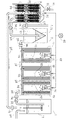
その装置は、図1に示すように、原廃水11を貯留し一定の流量で下流側に送る原水調整槽1と、上記原水調整槽1の下流側に複数槽を直列に設け、その内部に高単位に活性微生物を固着固定させ得る接触材2a、2b、2cを配置してこれに活性微生物を固着固定させ、底部にエアレータ3a、3b、3cを設け、槽内の溶存酸素量を2〜7ppmに維持して、BOD−接触材容積負荷3.5〜7kg/m3の下で排水処理するものとしたばっき槽4a、4b、4cと、該ばっき槽4a、4b、4cを経て汚濁物質を汚泥12として沈殿させ、その上澄液を放流水として排出する沈殿槽5と、その内部に高単位に活性微生物を固着固定させ得る接触材2dを配置してこれに活性微生物を固着固定させ、底部にエアレータ3dを設けて槽内の溶存酸素量を2〜7ppmに維持しつつ、上記沈殿槽5に沈殿する汚泥12を取り込みBOD−接触材容積負荷3.5〜7kg/m3の下で汚泥を消化処理する汚泥消化槽6とで構成したものである。
【0028】
また、前記原水調整槽1から前記ばっき槽4aへの送液配管p1、前記ばっき槽4cから前記沈殿槽5への送液配管p2、前記沈殿槽5から処理水13を系外へ放流する送液配管p3、前記沈殿槽5から汚泥消化槽6への送液配管p4、及び前記汚泥消化槽6から前記原水調整槽1への送液配管p5のそれぞれの途中に磁気処理機9a、9b…9eを外装して、それらの管内を通過する液体に磁力を与えるようにしたものである。
【0029】
前記ばっき槽4a、4b、4cは、このように3槽に分けて直列に接続したもので、各槽の内部には活性微生物を高単位に固着固定させた接触材2a、2b、2cを配置し、各槽の底部にはエアレータ3a、3b、3cを設けて、前述の溶存酸素量及びBOD−接触材容積負荷3.5〜7kg/m3の下で排水処理するように構成した。
【0030】
前記接触材2a、2b、2cは、この実施例では、セラミックスによって口径を20mm程度、長さを500mm程度、口径の中心に8mm程度の孔を開けて中空星型柱状体に成形したものを採用し、これを複数個束ねた上で、それぞれ前記ばっき槽4a、4b、4cの上部の固定バー8a、8b、8cから吊り下げることとしたものである。
【0031】
前記接触材2a、2b、2cは焼成したものであり、焼成の過程で有機質は焼却され、残存する無機質によって多孔性で表面積が大きなものになっている。これらには、リン、カルシウム及びマグネシウムなどのミネラル分が適量に含むものとなり、更に、遠赤外線を発生するものとなっている。
【0032】
そのためにその多孔性で表面積が大きいことが、活性微生物の生息に良好な住処となるばかりか、前記ミネラル分が活性微生物の健全な生育に役立ち、活性微生物が遠赤外線の照射を受けることによってその活動が一層活発化するものとなる。
また、その多孔性の小孔は、被処理物のBOD汚濁負荷の高低に応じて、活性微生物がその小孔から処理に必要な分だけ自由に出入りできるようになったり、処理に係わった活性微生物が、再び小孔に入り込んで槽内に留まり休息することができるようになったりなどと、活性微生物にとって非常に好都合なものとなるものである。
このような前記接触材2a、2b、2cの特性は、従来から用いられている市販の接触材、例えば、波板やハニカム材等には保持されていないものであって、活性微生物にとっては極めて有用なものになるものである。
【0033】
また、前記接触材2a、2b、2cは、前記ばっき槽4a、4b、4cの上部から吊り下げたので、各槽の中では底部に配置したエアレータ3a、3b、3cからの圧縮空気の流れと液の流れとに乗って自然とゆらゆら動くような状態となる。
これによって、好気的環境下のもとで、BOD汚濁成分と前記接触材2a、2b、2cに生息する活性微生物との接触が、活性微生物にとって極めて好ましい状態で行われることとなり処理が効果的に進むものとなる。
【0034】
更に、前記接触材2a、2b、2cである前記中空星型柱状体の中空部分等は、槽内では死角となり易いので好気性がやや損なわれて疑似嫌気性状態となって、この部分には通性嫌気性菌や嫌気性菌が生息するようになる。しかし、このような通性嫌気性菌や嫌気性菌は、槽内に多数生息している好気性菌が有機物に作用する前に、有機物にアタックして分解を開始させる働きを保持していると考えられているので、有機物の分解を段階的に促進することとなり好ましい状態を形成するものとなるのである。
【0035】
また、前記接触材2a、2b、2cには、有機物の分解を司る活性微生物をBOD−接触材容積負荷3.5〜7kg/m3の下で処理できるように高単位に固着固定させるものである。この活性微生物は、自然界に生息するものであって、細菌類あるいは菌類を主たる構成生物として、原生動物、後生動物を従属出現生物として構成される複合生物群である。
【0036】
このような活性微生物による処理は、通常の活性汚泥法ではBOD−容積負荷0.4kg/m3程度で、生物膜法ではBOD−容積負荷0.8kg/m3程度で行われるものであるが、本発明ではBOD−接触材容積負荷3.5〜7kg/m3で処理を行うものである。
【0037】
このような高いBOD−接触材容積負荷の下での処理を行うように設定したのは、処理の効率をより高めるためであって、この高いBOD−接触材容積負荷の下での処理が可能となったのは、前記接触材を適切な材料によって適切に成形しこれを適切に配して用いたこと、及び処理に於ける溶存酸素量を2〜7ppmと高めるようにしたこととが、その主たる理由である。
また、繰り返し行ったテスト結果から前記接触材2a、2b、2cには、通常の接触材に比べて15倍〜最大100倍の活性汚泥(活性微生物)を付着させることができる結果が得られている。
【0038】
そしてこのような高い接触材容積負荷の下での処理を可能としたことによって、ばっき槽の容積は従来の1/3〜1/4程度に小さくすることができる上に、活性微生物相が壊れてバルキングを起こしたり、前記接触材2a、2b、2cに目詰まりを起こしたりなどのトラブルを発生することもなく、また、臭気や泡を発生させることもなく、効率よく安定して処理することができるものとなる。
【0039】
この活性微生物の働きは、一般に知られているように、廃水中の溶解性有機物を吸収して、溶存酸素を消費しながら有機物を酸化分解して二酸化炭素と水とを生成させると共に、一方で炭素、水素、酸素とを作用させて蛋白質を合成し自己細胞に取り込んで増殖して行くものである。
これらの働きは全て活性微生物の酵素反応であって、細菌類、菌類あるいは死物栄養性原生動物が生活エネルギーを得るためのものである。このようにして活性微生物の活動機構ができあがると、排水処理の主役である細菌類、菌類あるいは死物栄養性原生動物の他に、これらを捕食する上位の生物である活動性原生動物や、更にこれを捕食する後生動物が共存する生物相を形成するに至り、一つの鎖の中で有機的なつながりとなる食物連鎖、即ち、生物ピラミッドができ上がって、安定した活性微生物処理が行われるようになるものである。
【0040】
前記エアレータ3a、3b、3cとして前記特公平6−36915号公報に開示されているものと同じものを採用したが、その構造については、既にその説明中に記載したのでここでは省略する。
なお、前記エアレータ3a、3b、3cによるエアレーションの程度については、原廃水11のBOD汚濁負荷の高低に応じて調整できるようにしたものである。汚濁負荷が高いときにはエアレーションの空気量を多めに、汚濁負荷が低いときにはエアレーションの空気量を少なめに送るように調整することにより、槽内の溶存酸素量は2〜7ppmに維持されるので、前記接触材2a、2b、2cに生息する活性微生物相に変化が生じることがなくなり、安定した処理が維持されるものとなる。
【0041】
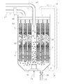
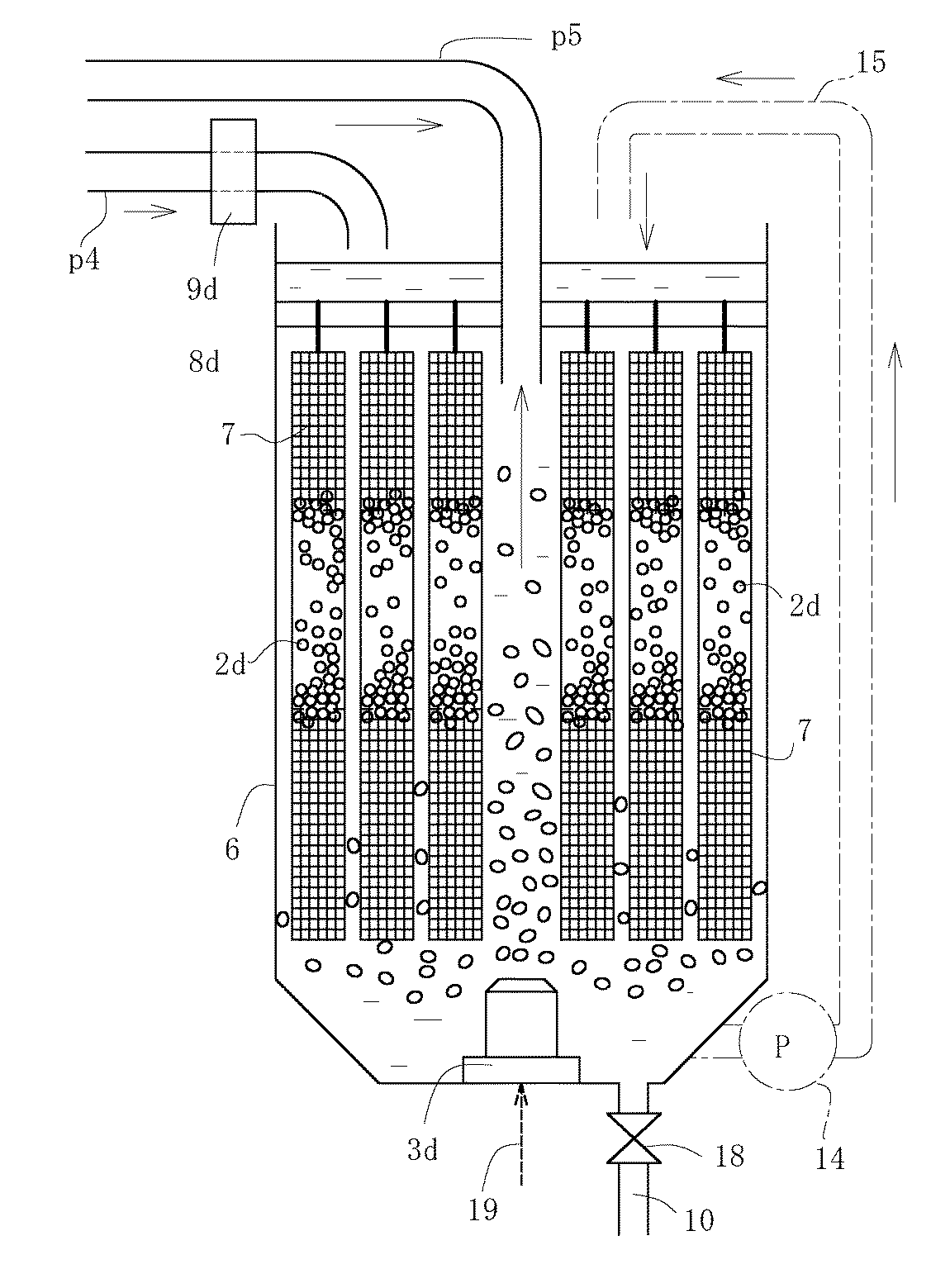
前記汚泥消化槽6は、図2に示したように、その内部に接触材容積負荷3.5〜7kg/m3の下で消化処理できる接触材2dを配置してこれに活性微生物を高単位に生息させ、底部にエアレータ3dを設け、槽内の溶存酸素量を2〜7ppmに維持するようにし、前記沈殿槽5に沈殿する汚泥12を取り込む配管及び消化処理済液を前記原水調整槽1に返送する配管を付設し、更に、底部に消化処理によって処理系内に残る無機汚泥を引抜く時に用いる無機汚泥引抜き管10及びバルブを付設して構成するものである。
【0042】
また、前記汚泥消化槽6には、図2に一点鎖線で示すように、ポンプ14及び配管15を付設して、槽内底部の汚泥12を上部まで汲み上げ、これを前記接触材2dに上から掛け、汚泥循環を行うように構成しても良い。このように構成することによって、汚泥消化の効率が一層高まると共に汚泥の沈降性が改善されるものとなるからである。
更に、前記汚泥消化槽6は、この実施例では単数槽であるが、原廃水11のBOD汚濁負荷に応じて複数槽を直列に設けるものとしても良い。
【0043】
前記接触材2dは、前記ばっき槽に用いるものと同様なものを用いることができるが、この実施例では、小球状体(口径が20mm)を採用した。複数の細長のメッシュ袋7、7…の中に上記小球状体を多数個充填し、それらの各メッシュ袋7、7…を前記汚泥消化槽6の上部に配した固定バー8dから吊り下げたものである。これらの接触材2dには、前記ばっき槽4a、4b、4cの接触材2a、2b、2cと同様に、活性微生物を高単位に固着固定させるものである。
【0044】
また、前記接触材2dの特性、前記汚泥消化槽6の上部に設けた固定バー8dに吊り下げた効果、前記接触材2dに生息する微生物相及び底部に配置したエアレータ3dについては、前記ばっき槽4a、4b、4cに関する説明と同様であるのでここでは省略する。
【0045】
更に、既に述べたように、前記原水調整槽1から前記ばっき槽4aへの送液配管p1、前記ばっき槽4cから前記沈殿槽5への送液配管p2、前記沈殿槽5から処理水13を系外へ放流する送液配管p3、前記沈殿槽5から汚泥消化槽6への送液配管p4及び前記汚泥消化槽6から前記原水調整槽1への送液配管p5のそれぞれの途中には各々磁気処理機9a、9b…9eを外装し、それらの管内を通過する液体に磁力を与えるものである。
【0046】
このような磁気処理機9a、9b…9eは、永久磁石から発生する磁気力によって、原廃水や浄化過程の廃水の水分子が集団(クラスター)化している状態を分離させ微粒子化させることによって、水が本来持っている活性力を向上させ、これによって廃水の浄化を促進させるものである。
また、特に浄化過程の廃水では、発生した汚泥の沈降が容易となり、汚泥と処理水との分離がし易いものとなる。
【0047】
即ち、原廃水11や浄化過程の廃水は、水分子の極性や不純物質などが仲介となり水分子相互が引き合うことで大きなクラスターを形成していて、水が本来持っている活性力が低減している状態にある。
このような状態にある原廃水11や浄化過程の廃水を、前記磁気処理機9a、9b…9eを外装した配管によって送液することとすれば、その際に、これらの原廃水11や浄化過程の廃水が磁場を通過することとなって、瞬時に水分子の極性がプラスとマイナスに引き分けられ、クラスター化している水分子が激しくスピン現象を起こして、水分子相互の結合を解き、微粒子化することとなって、水分子の運動力が高まり、水が本来持っている活性力が向上するようになる。なお、当然ながら、配管には磁気遮蔽が作用しない非磁性体を採用する。
【0048】
なお図中、p6、p7は、それぞればっき槽4a、4b間、ばっき槽4b、4c間の送液配管、p8は原水導入用の配管、16、17はそれぞれポンプ、18はバルブ、19はエア送給用の配管、20は圧縮空気の発生機である。
【0049】
次に本発明の排水処理装置による一連の排水処理過程を説明する。
図1に示すように、前記原水調整槽1に原廃水11を導入し、該原水調整槽1から該原廃水11を一定の流量で最前段のばっき槽4aに送り込む。ばっき槽4a、4b、4cでは、送り込まれた原水をその順序で後段に移動させながら、各槽の底部に配置したエアレータ3a、3b、3cによってその中に空気を送り込み、溶存酸素量を2〜7ppmに維持しつつ、槽内の接触材2a、2b、2cに高単位に固着固定されている活性微生物によって、BOD−接触材容積負荷3.5〜7kg/m3の下で、原水中のBOD汚濁成分を所定の時間かけて処理する。
【0050】
ばっき槽4a、4b、4cで処理が済んだ処理液は次段の沈殿槽5へ送り込まれ、汚泥12と処理水13とに分離される。該沈殿槽5の底部に沈殿した汚泥12は汚泥消化槽6へ送り込まれ、上澄みの処理水13は放流水として系外へ排出される。なお前記処理条件の下で処理された上記処理液は、前記沈殿槽5中で、汚泥12と処理水13との分離が極めて良好なものとなっている。
【0051】
前記汚泥消化槽6に送り込まれた汚泥12は、底部に配置したエアレータ3dによってその中に空気が送り込まれ、その溶存酸素量を2〜7ppmに維持しつつ、槽内の接触材2dに高単位に固着固定されている活性微生物によって、BOD−接触材容積負荷3.5〜7kg/m3 の下で、所定の時間(24〜48時間程度)処理され、その中の有機汚泥が二酸化炭素と水とに消化される。
ここで通常、汚泥消化槽6へ送られる汚泥の濃度は10000ppm前後であるが、汚泥消化槽6で消化処理されることによって6000ppm前後に下がってくる。この程度にまで消化処理を行った処理済液が、原水調整槽1へ戻され、排水処理系内で再処理されることとなる。
【0052】
以上のように、処理済液が、その汚泥濃度(SS)6000ppm前後で原水調整槽1に返送されると、この処理済液中には活性化された微生物が多数生息しているので、これらが順次ばっき槽4a、4b、4cの中に送られることになり、これによって、該ばっき槽4a、4b、4c中での原廃水の処理が極めて有効に行われることとなるものである。
更に、前記汚泥消化槽6には、先に述べ、かつ図2に一点鎖線で示したように、その下部から上部に繋がる配管15を配し、その途中にポンプ14を挿入して槽内に取り込んだ汚泥12を、該ポンプ14により該配管15を通じて上部まで汲み上げ、これを前記接触材2dの上方から掛けるようにして汚泥循環を行うことにした場合は、汚泥消化の効率を高めると共に汚泥沈降性を改善することができるようになり一層好ましいものとなる。
【0053】
なお汚泥消化槽6での汚泥消化処理は、連続処理として構成したが、バッチ処理としても良い。連続処理とした場合の返送水の配管p5は、図1及び図2に示すように、その一端を汚泥消化槽6の上部に配設して図示しないポンプによって汲み上げ、他端を延長接続した原水調整槽1に返送すれば良い。これに対してバッチ処理とした場合の返送水の配管は、その一端を汚泥消化槽6の下部にまで延長して配設しておき、その途中に枝管とバルブとを設置して、所定の時間(例えば24時間程度)静置して、層分離してくるモヤモヤとした付近までの上澄液をポンプによって汲み上げ、他端を延長接続した原水調整槽1に返送すれば良い。
【0054】
消化処理の過程では、汚泥消化の進行具合を確認する機器により、例えば、MLSS計等によって槽内の汚泥濃度をチエックして、沈殿槽5からの汚泥12の送り込み量、エアレータのエアレーション強度及び前記原水調整槽1への処理済液の返送量などを適度に調節する。
【0055】
このような排水処理装置により排水処理することにより、排水処理系内から排出される汚泥量は、無機成分を主体としたものが少量に発生するだけとなって、従来の排水処理装置からの汚泥発生量に比べて、およそ、1/5〜1/10程度となり、汚泥処理に要する費用が大幅に軽減されるものとなる。
また、このような一連の処理に於いては、臭気や泡の発生もなく作業性は極めて良いものである。
なお、消化処理によって無機汚泥は、処理系内に増加してくるが、これについては前記汚泥消化槽6の底部に付設した無機汚泥引抜き管10によって定期的に抜き出して脱水施設及び焼却施設で別に処理を行うものとする。
【0056】
<テスト例>
次にテスト例によって本発明を具体的に説明するが、これは本発明の効果を説明するためのものであって、これによって本発明が限定されるものではない。
【0057】
<テスト例1>
某病院の人口透析部門から発生するBOD汚濁濃度1300〜2000ppm、廃水量4.5m3/日の原廃水に対して、図1に示したブロック図による排水処理装置を用いてテスト処理を行った。
【0058】
<テスト例2>
某納豆工場から発生するBOD汚濁濃度1500〜2300ppm、廃水量60m3/日の原廃水に対して、図1に示したブロック図による排水処理装置を用いてテスト処理を行った。
【0059】
<テスト処理における試験項目>
テスト例1及びテスト例2のテスト処理に於いて、処理を開始して5日後、10日後及び30日後の原廃水11及び処理水13に対しては、BOD及びSSを、沈殿槽5から汚泥消化槽6への取り込み汚泥12(汚泥液)及び汚泥消化槽6から原水調整槽1への返送水に対しては、SS(MLSS)を、それぞれ次に示す測定方法により測定して、テスト例1の結果は下記の表1に、テスト例2の結果は下記の表2にまとめた。
【0060】
<試験項目の測定方法>
BOD及びSSの測定方法は次の方法により行った。
BOD : JIS K0102 21に基づき測定した。単位 ppm。
SS : S46環告59付表8に基づき測定した。単位 ppm。
【0061】
【表1】
【表2】
<テスト結果の考察>
テスト例1及びテスト例2の結果を見ると、処理水に対しては、いずれも5日後のBOD、SSの値はBODで30ppm台、SSで20ppm台となっていて良好な排水処理がなされてきていることが判る。また、10日後のBOD、SSの値はいずれも10ppm台に、30日後のBOD、SSの値はいずれも一桁となっていて極めて良好に排水処理がなされていることが判る。
【0064】
また、返送水に対しては、いずれも5日後のSSの値は8600ppm前後となっていて汚泥の消化が進んできていることが判る。また、10日後及び30日後のSSの値は6000ppm前後なっていて汚泥の消化が良好に行われていることが判る。
なお、通常は沈殿槽で沈殿する引き抜き汚泥液の濃度は1%(=10000ppm)程度であって、汚泥消化槽から原水調整槽へ返送される返送水のSSの値が前記結果のように6000ppm前後になっていることは、槽内での汚泥消化が良好になされていると判断できるものである。
【0065】
【発明の効果】
以上述べたように、本発明の1の排水処理装置によれば、排水処理によって発生した汚泥は有機性汚泥であるので、前記汚泥消化槽の前記接触材に高単位に固着固定させた活性微生物によって、前記接触材に目詰まりを起こすことなく、臭気や泡を発生させることもなく、短時間に効率よく二酸化炭素と水とに分解消化することができる。
排水処理によって系内に残る汚泥は、無機成分を主体とした少量の汚泥となるので、従来の排水処理装置から発生する汚泥量に比べて、およそ、1/5〜1/10程度となり、汚泥処理に要するコストが大幅に低減されるものとなる。
【0067】
更に本発明の1の排水処理装置によれば、前記接触材の中空星型柱状体及び小球状体はいずれも焼成したもので、その焼成過程で有機質は焼却され、無機質によって多孔性で表面積が大きなものに構成されたものとなる。また、小球状体としたものには、リン、カルシウム及びマグネシウムなどのミネラル分が適量に含むものとなり、更に、遠赤外線を発生するものとなっている。
そのために多孔性で表面積が大きいことが活性微生物の生息に良好な住処となるばかりか、ミネラル分が活性微生物の健全な生育に役立ち、活性微生物が遠赤外線の照射を受けることによってその活動が一層活発化するものとなる。
また、その多孔性の小孔は、被処理物のBOD汚濁負荷の高低に応じて、活性微生物がその小孔から処理に必要な分だけ自由に出入りできるようになったり、処理に係わった活性微生物が、再び小孔に入り込んで槽内に留まり休息することができるようになったりなどと、活性微生物にとってコロニーを作るのに非常に好都合なものとなる。
【0068】
また、前記接触材は、前記ばっき槽又は前記汚泥消化槽の上部から吊り下げたものであるので、各槽の中では、底面に配置したエアレータからの圧縮空気の流れと各液の流れとに乗って自然とゆらゆら動くような状態となる。
これによって、前記接触材に生息する活性微生物とBOD汚濁成分又は汚泥との接触が、好気的環境下のもとで、活性微生物にとって極めて好ましい状態で行われることとなり、効果的に処理が進むこととなる。
【0069】
また、このような接触材に活性微生物を高単位に固着固定させ、前記ばっき槽及び前記汚泥消化槽内に配置して処理を行うと、好気的環境下の効果と相まって、高負荷の下で処理を行っても前記接触材に目詰まりを起こすことはなく、逆洗などを行う必要もなく、また、汚泥が沈降することもないので作業性が極めて良いものとなる。
【0070】
更に、前記中空星型柱状体の中空部分、前記中空筒状体の中空部分及び前記小球状体相互が接触した部分は、好気性がやや損なわれて疑似嫌気性状態となり、この部分には通性嫌気性菌や嫌気性菌が生息するようになる。これらの菌は、槽内に多数生息している好気性菌が作用する前に、有機物にアタックして分解を開始させる働きを保持していると考えられているので、有機物の分解を段階的に促進させることとなり好ましい状態を形成するものとなる。
【0071】
本発明の2の排水処理装置によれば、以上の本発明の1の効果に加えて、原廃水中のBOD汚濁成分が、前記ばっき槽の前記接触材に高単位に固着固定させた活性微生物によって、ばっき槽の容積を従来の1/3〜1/4の容積とした条件下で、前記接触材に目詰まりを起こすことなく、臭気や泡を発生させることもなく、効率よく安定して処理することができるものである。
【図面の簡単な説明】
【図1】一実施例の排水処理装置の全体構造を示すブロック図。
【図2】一実施例の排水処理装置の汚泥消化槽の構造を示す縦断側面図。
【符号の説明】
1 原水調整槽
2a、2b、2c、2d 接触材
3a、3b、3c、3d エアレータ
4a、4b、4c ばっき槽
5 沈殿槽
6 汚泥消化槽
7 メッシュ袋
8a、8b、8c、8d 固定バー
9a、9b、9c、9d、9e 磁気処理機
10 無機汚泥引抜き管
11 原廃水
12 汚泥
13 処理水
14、16、17 ポンプ
15 配管
18 バルブ
19 エア送給用の配管
20 圧縮空気の発生機
p1、p2、p3、p4、p5、p6、p7 送液配管
p8 原水導入用の配管[0001]
BACKGROUND OF THE INVENTION
The present invention relates to a wastewater treatment apparatus for purifying wastewater containing organic pollutants (BOD components) at a high concentration, and relates to a wastewater treatment apparatus for digesting sludge generated by wastewater treatment with active microorganisms.
[0002]
[Prior art]
Conventionally, a sewage treatment method using active microorganisms has been widely adopted as a treatment method for purifying various sewage containing organic pollutants (BOD components). For example, wastewater from artificial dialysis containing high-concentration BOD-contaminating components, wastewater from the natto factory, wastewater from the ham factory, etc. are treated using the action of the active microorganisms as necessary. In addition, the treatment is performed in combination with the coagulation precipitation method using a coagulant.
[0003]
The wastewater from the artificial dialysis in the above example has high concentrations of organic pollutants such as acetic acid and glucose contained in artificial dialysis fluid, as well as protein metabolites urea, uric acid, creatinine, guanine derivatives, potassium, phosphorus, etc. Included. Therefore, in such wastewater wastewater treatment, in the conventional sludge purification apparatus using activated sludge using active microorganisms, removal of BOD pollutant components becomes unstable, or the amount of sludge generated by purification is extremely large. New problems are to be raised in this sludge treatment.
[0004]
In this regard, the present inventor has reviewed and improved the conventional sewage purification apparatus based on the activated sludge method as disclosed in Japanese Patent Publication No. 6-36915 (Patent No. 1914169) and the name “sewage purification apparatus”. ing.
[0005]
That is, in this review, a raw water adjustment tank that stores raw wastewater and sends it to the downstream side at a constant flow rate, a contact tank in which active microorganisms inhabit the inside, and a tank equipped with an aerator on the bottom, Install a modified aerator on the bottom of the wastewater tank in a wastewater purification system that consists of a sedimentation tank that precipitates the pollutants in the raw wastewater as sludge and discharges the supernatant as treated water. And a sludge digestion tank that takes in sludge that settles at the bottom of the sedimentation tank and digests the sludge with active microorganisms, and an improved aerator is proposed on the bottom.
[0006]
The improved aerator includes a nozzle for injecting compressed air from the bottom of a cylindrical cylinder toward the upper end opening of the cylinder, and an opening for introducing liquid into the outer periphery of the lower part of the cylinder A guide vane for rotating bubbles is provided on the inner peripheral side of the cylindrical body above this, and a plurality of protrusions are provided on the inner periphery on the guide vane.
[0007]
Thereby, the compressed air injected from the nozzle is rotated and stirred by the guide vane together with the water introduced from the opening, and further diffused and raised while colliding with the spherical protrusion on the upper part. For this reason, the air diffuses at a high concentration in the sewage and dissolves, and circulates in the tank. Therefore, the microorganisms in the plating tank are activated, and a higher treatment capacity for organic substances is exhibited.
[0008]
The sludge digestion tank is a tank in which an aerator having the same structure is installed on the bottom surface, and the sludge that has settled on the bottom of the sedimentation tank is taken into the sludge to be treated, and in that aerobic environment Below, sludge is digested into carbon dioxide and water by active microorganisms. Further, the treated water in the sludge digestion tank is returned to the tank and circulated in the wastewater treatment system.
[0009]
Therefore, according to the technique disclosed by the present inventors as described above, stable treatment can be performed as compared with the conventional method, and the generated sludge can be digested well, but the BOD pollution concentration is higher, And when the amount of wastewater is large, the wastewater treatment becomes unstable, the contact material in the tank is clogged, and the amount of sludge generated increases proportionally with the purification of sewage. Therefore, in order to digest this sludge, further improvement is desired, for example, the sludge digestion tank requires a large scale.
[0010]
[Problems to be solved by the invention]
The present invention enables stable wastewater treatment by active microorganism treatment even when treating raw wastewater with a high BOD pollution concentration and a large amount of wastewater, and most of the generated sludge is efficiently and efficiently produced by a compact sludge digester. It is an object of the present invention to provide a wastewater treatment apparatus that can be digested at low cost.
[0011]
[Means for Solving the Problems]
1 of the present invention is a raw water adjustment tank for storing raw wastewater and sending it downstream at a constant flow rate;
It consists of a plurality of tanks provided in series on the downstream side of the raw water adjustment tank, a contact tank in which active microorganisms are inhabited, and an aeration tank provided with an aerator at the bottom,
A sedimentation tank for precipitating pollutants in the raw wastewater as sludge through the batch tank, and discharging the supernatant as treated water;
A drainage provided with an aerator at the bottom, digesting sludge settled in the settling tank and digesting it in an aerobic state, and returning the treated liquid to the raw water adjustment tank or the flash tank In the processing equipment,
In the sludge digestion tank, BOD-contact material volumetric load 3.5 to 7 kg / m in the tankThreeA contact material capable of fixing and fixing active microorganisms in a high unit so that the sludge digestion treatment can be carried out, and the amount of dissolved oxygen in the sludge digestion tank can be maintained at 2 to 7 ppm at the bottom thereof. An aerator is installed in,
The contact material disposed in the batch tank and the sludge digestion tank has a diameter of 20 by ceramics. mm Degree, length 500 mm Degree, 8 in the center of the caliber mm A hollow star-shaped columnar body formed by opening a hole of a certain degree, or adding glass cullet powder to ceramic pieces powder, river sediment mud or lake sediment mud alone or a mixture thereof, and further binder Add 5-25 mm Formed into a small spherical body, and fired at a temperature of 800 to 1000 ° C.
When adopting a hollow star columnar body as the contact material, a plurality of them are bundled and suspended from the top of the flash tank and the sludge digestion tank,
When a fired small spherical body is employed as the contact material, the diameter is 40-60. mm Degree, length 800-1000 mm Put in a hollow cylindrical body with a large number of small holes or slender mesh bags, and hang from the top of the flash tank and sludge digestion tankWastewater treatment equipment.
[0012]
Therefore, according to the wastewater treatment apparatus of the present invention, the contact material is clogged by the active microorganisms in which organic sludge generated by the wastewater treatment is fixed and fixed to the contact material of the sludge digestion tank in a high unit. In addition, it can be efficiently digested into carbon dioxide and water in a short time without generating odor and bubbles.
Thus, the sludge remaining in the system by the wastewater treatment becomes a small amount of sludge mainly composed of inorganic components, which is about 1/5 to 1/10 of the amount of sludge generated from the conventional wastewater treatment equipment. The cost required is greatly reduced.
[0016]
In addition, according to the waste water treatment apparatus 1 of the present invention,Since the hollow star-shaped columnar body and the small spherical body are both formed by firing, the organic matter is incinerated during the firing process, and becomes a porous inorganic member having a large surface area. Further, the small spherical body contains an appropriate amount of minerals such as phosphorus, calcium and magnesium, and further generates far infrared rays.
[0017]
As described above, the hollow star-shaped columnar body and the small spherical body are not only a good living place for active microorganisms to be porous, but also having a large surface area, and the mineral content is useful for the healthy growth of the active microorganisms. When the active microorganisms are irradiated with far-infrared rays from these, the activity is further increased.
[0018]
In addition, the porous small holes formed in them can allow active microorganisms to freely enter and exit from the small holes according to the level of BOD contamination load of the object to be processed, For example, the active microorganisms involved in the treatment can enter the small holes again, stay in the tank and rest, and are very convenient for the active microorganisms to form a colony.
[0019]
Moreover, since the contact material is suspended from the upper part of the flash tank or the sludge digestion tank, in each tank, it rides on the flow of compressed air from the aerator disposed on the bottom surface and the flow of each liquid. It will be in a state where it moves naturally and fluctuates.
As a result, the contact between the active microorganisms inhabiting the contact material and the BOD-contaminating component or sludge is performed in an extremely favorable state for the active microorganisms under an aerobic environment, and the treatment proceeds effectively. It becomes.
[0020]
Moreover, when the active microorganisms are fixed and fixed in a high unit on such a contact material and disposed in the flash tank and the sludge digestion tank, the treatment is performed in combination with the effect under an aerobic environment. Even if the treatment is performed under the condition, the contact material is not clogged, it is not necessary to perform backwashing, and the sludge does not settle down, so that the workability is extremely good.
[0021]
Furthermore, the hollow part of the hollow star columnar body, the hollow part of the hollow cylindrical body, and the part where the small spherical bodies are in contact with each other are slightly aerobic and become a pseudo-anaerobic state. Facultative anaerobes and anaerobic bacteria become inhabited. These bacteria are thought to retain the function of attacking organic substances and initiating decomposition before the aerobic bacteria that inhabit many in the tank act. Therefore, a preferable state is formed.
[0022]
2 of the present invention isA raw water adjustment tank that stores raw wastewater and sends it to the downstream side at a constant flow rate,
It is composed of a plurality of tanks provided in series on the downstream side of the raw water adjustment tank, a contact tank in which active microbes are inhabited therein, and an aeration tank provided with an aerator at the bottom,
A sedimentation tank for precipitating the pollutants in the raw wastewater as sludge through the above-described tank, and discharging the supernatant as treated water;
A drainage provided with an aerator at the bottom, digesting sludge that settles in the settling tank in an aerobic state, and returning the treated liquid to the raw water adjustment tank or the flash tank In the processing equipment,
In the sludge digestion tank, BOD-contact material volumetric load 3.5-7 in the tank kg / m Three A contact material capable of fixing and fixing active microorganisms in a high unit so that the sludge digestion treatment can be performed under the sludge, and the dissolved oxygen amount in the sludge digestion tank is set to 2 to 7 at the bottom. ppm An aerator is provided so that it can be maintained at
BOD-contact material volume load 3.5-7 in the tank kg / m Three The contact material capable of fixing and fixing the active microorganisms in a high unit is disposed so that the wastewater treatment can be performed under the waste water, and the dissolved oxygen amount in the sludge digestion tank is set to 2 to 7 at the bottom thereof. ppm An aerator is provided so that it can be maintained at
The contact material disposed in the batch tank and the sludge digestion tank has a diameter of 20 by ceramics. mm Degree, length 500 mm Degree, 8 in the center of the caliber mm A hollow star-shaped columnar body formed by opening a hole of a certain degree, or adding glass cullet powder to ceramic pieces powder, river sediment mud or lake sediment mud alone or a mixture thereof, and further binder Add 5-25 mm Formed into a small spherical body, and fired at a temperature of 800 to 1000 ° C.
When adopting a hollow star columnar body as the contact material, a plurality of them are bundled and suspended from the top of the flash tank and the sludge digestion tank,
When a fired small spherical body is employed as the contact material, the diameter is 40-60. mm Degree, length 800-1000 mm It is a wastewater treatment apparatus which is placed in a hollow cylindrical body having a large number of small holes or slender mesh bags and is suspended from the upper part of the flash tank and the sludge digestion tank.
[0023]
Therefore, according to the wastewater treatment apparatus of 2 of the present invention, in addition to having all the effects of 1 of the present invention, the BOD contamination component of the raw wastewater has a volume of the conventional tank that treats this. Even if the volume is / 3 to 1/4, the active microorganisms fixed and fixed in high units to the contact material filled therein may generate odors and bubbles without causing clogging of the contact material. And can be processed efficiently and stably.
[0026]
DETAILED DESCRIPTION OF THE INVENTION
Hereinafter, embodiments of the present invention will be described in detail based on examples with reference to the drawings.
FIG. 1 is a block diagram showing the overall structure of one embodiment of the sewage purification apparatus of the present invention, and FIG. 2 is a longitudinal side view showing the structure of a sludge digestion tank of one embodiment of the sewage purification apparatus of the present invention.
[0027]
The wastewater treatment device of the present invention is a wastewater treatment device that purifies wastewater containing organic pollutants at a high concentration and digests sludge generated by wastewater treatment with active microorganisms.
As shown in FIG. 1, the apparatus is provided with a raw water adjusting tank 1 for storing
[0028]
Also, a liquid feed pipe p1 from the raw water adjustment tank 1 to the
[0029]
The
[0030]
In this embodiment, the
[0031]
The
[0032]
Therefore, its porous and large surface area not only makes it a good place to live active microorganisms, but the minerals help the healthy microorganisms grow, and the active microorganisms are irradiated with far-infrared rays. Activities will become even more active.
In addition, the porous small pores allow the active microorganisms to freely enter and exit from the small pores according to the level of the BOD pollution load of the object to be treated, and the activity related to the treatment For example, microorganisms can reenter the small holes and stay in the tank to be able to rest, which is very convenient for the active microorganisms.
Such characteristics of the
[0033]
Further, since the
As a result, the contact between the BOD contaminating component and the active microorganisms that inhabit the
[0034]
Furthermore, the hollow portions of the hollow star-shaped columnar bodies that are the
[0035]
Further, the
[0036]
Such a treatment with active microorganisms is performed by a normal activated sludge method using a BOD-volume load of 0.4 kg / m.ThreeIn the biofilm method, BOD-volumetric load 0.8kg / mThreeIn the present invention, the BOD-contact material volumetric load is 3.5 to 7 kg / m.ThreeThe process is performed.
[0037]
The reason for setting the processing under such a high BOD-contact material volume load is to further increase the processing efficiency, and the processing under this high BOD-contact material volume load is possible. The reason was that the contact material was appropriately formed from an appropriate material and was appropriately disposed and used, and the amount of dissolved oxygen in the treatment was increased to 2 to 7 ppm. That is the main reason.
Further, from the repeated test results, the
[0038]
And by enabling the treatment under such a high contact material volume load, the volume of the flash tank can be reduced to about 1/3 to 1/4 of the conventional one, and the active microbial flora can be reduced. No troubles such as breaking and bulking or clogging of the
[0039]
As is generally known, this active microorganism works by absorbing dissolved organic matter in wastewater and oxidatively decomposing the organic matter while consuming dissolved oxygen to produce carbon dioxide and water. Carbon, hydrogen, and oxygen act to synthesize proteins, take them into their own cells, and proliferate.
All of these functions are enzymatic reactions of active microorganisms, and are used by bacteria, fungi, or carnivorous protozoa to obtain living energy. When the active mechanism of active microorganisms is completed in this way, in addition to bacteria, fungi or dead-nutritive protozoa that are the main players in wastewater treatment, active protozoa that are upper organisms that prey on these, It leads to the formation of a biota that coexists with metazoans that prey on it, so that a food chain that is an organic connection in one chain, that is, a biological pyramid, is created, and stable active microbial treatment is performed. It will be.
[0040]
As the
The degree of aeration by the
[0041]
As shown in FIG. 2, the
[0042]
Further, as shown by a one-dot chain line in FIG. 2, the
Furthermore, although the said
[0043]
As the
[0044]
Further, the characteristics of the
[0045]
Furthermore, as already described, the liquid feed pipe p1 from the raw water adjustment tank 1 to the
[0046]
Such
In particular, in the waste water in the purification process, the generated sludge can be easily settled, and the sludge and the treated water can be easily separated.
[0047]
In other words, the
If the
[0048]
In the figure, p6 and p7 are the liquid supply pipes between the
[0049]
Next, a series of wastewater treatment processes by the wastewater treatment apparatus of the present invention will be described.
As shown in FIG. 1,
[0050]
The treatment liquid that has been treated in the
[0051]
The
Here, normally, the concentration of the sludge sent to the
[0052]
As described above, when the treated liquid is returned to the raw water adjustment tank 1 at a sludge concentration (SS) of about 6000 ppm, there are many activated microorganisms in the treated liquid. Are sequentially sent into the
Further, the
[0053]
In addition, although the sludge digestion process in the
[0054]
In the process of digestion, the sludge concentration in the tank is checked by, for example, an MLSS meter or the like using a device for confirming the progress of sludge digestion, the amount of
[0055]
By performing wastewater treatment with such a wastewater treatment device, the amount of sludge discharged from the wastewater treatment system is generated only in a small amount mainly composed of inorganic components. Compared with the amount generated, it is about 1/5 to 1/10, and the cost required for the sludge treatment is greatly reduced.
Further, in such a series of treatments, workability is extremely good without generation of odor and bubbles.
In addition, inorganic sludge increases in the treatment system due to the digestion treatment, and this is periodically extracted by the inorganic
[0056]
<Test example>
Next, the present invention will be specifically described with reference to test examples, but this is for explaining the effects of the present invention, and the present invention is not limited thereby.
[0057]
<Test example 1>
BOD pollution concentration generated from the dialysis department of Sakai Hospital 1300-2000ppm, wastewater volume 4.5mThreeThe test treatment was performed on the raw wastewater per day using the wastewater treatment apparatus according to the block diagram shown in FIG.
[0058]
<Test example 2>
BOD pollution concentration generated from Kashiwa Natto factory is 1500-2300ppm and wastewater is 60mThreeThe test treatment was performed on the raw wastewater per day using the wastewater treatment apparatus according to the block diagram shown in FIG.
[0059]
<Test items in test processing>
In the test processing of Test Example 1 and Test Example 2, 5 days, 10 days, and 30 days after the start of processing, the
[0060]
<Measurement method of test items>
BOD and SS were measured by the following method.
BOD: Measured based on JIS K0102 21. Unit ppm.
SS: Measured based on Table 46 in Appendix S59. Unit ppm.
[0061]
[Table 1]
[Table 2]
<Consideration of test results>
Looking at the results of Test Example 1 and Test Example 2, for the treated water, the BOD and SS values after 5 days are both in the 30 ppm range for BOD and in the 20 ppm range for SS. You can see that In addition, the values of BOD and SS after 10 days are both in the 10 ppm range, and the values of BOD and SS after 30 days are both single digits.
[0064]
In addition, for the return water, the SS value after 5 days is around 8600 ppm, indicating that the digestion of sludge is progressing. Moreover, the value of SS after 10 days and 30 days is about 6000 ppm, and it can be seen that the sludge is digested well.
Normally, the concentration of the extracted sludge liquid precipitated in the settling tank is about 1% (= 10000 ppm), and the SS value of the return water returned from the sludge digestion tank to the raw water adjustment tank is 6000 ppm as in the above result. It can be judged that the sludge digestion in the tank has been made well before and after.
[0065]
【The invention's effect】
As described above, according to the wastewater treatment apparatus of the present invention, since the sludge generated by the wastewater treatment is organic sludge, the active microorganisms fixed and fixed to the contact material of the sludge digestion tank in a high unit. Thus, the contact material can be efficiently decomposed and digested into carbon dioxide and water in a short time without causing clogging of the contact material and without generating odor or bubbles.
The sludge remaining in the system due to the wastewater treatment is a small amount of sludge mainly composed of inorganic components, and is about 1/5 to 1/10 of the amount of sludge generated from the conventional wastewater treatment equipment. The cost required for processing is greatly reduced.
[0067]
Furthermore, according to the wastewater treatment apparatus 1 of the present invention,Both the hollow star columnar body and the small spherical body of the contact material are fired, the organic matter is incinerated during the firing process, and the porous material is constituted by the inorganic material to have a large surface area. Moreover, what was made into the small spherical body contains minerals, such as phosphorus, calcium, and magnesium, in an appropriate amount, and also generates far infrared rays.
Therefore, not only is the porous and large surface area a good place to live active microorganisms, but the minerals contribute to the healthy growth of active microorganisms. It becomes active.
In addition, the porous small pores allow the active microorganisms to freely enter and exit from the small pores according to the level of the BOD pollution load of the object to be treated, and the activity related to the treatment For example, microorganisms can reenter the small holes and stay in the tank to rest, making it very convenient for the active microorganisms to form colonies.
[0068]
Further, since the contact material is suspended from the upper part of the flash tank or the sludge digestion tank, in each tank, the flow of compressed air and the flow of each liquid from the aerator disposed on the bottom surface It will be in a state where it will move naturally swinging on.
As a result, the contact between the active microorganisms inhabiting the contact material and the BOD-contaminating component or sludge is carried out in an extremely favorable state for the active microorganisms under an aerobic environment, and the treatment proceeds effectively. It will be.
[0069]
In addition, when the active microorganisms are fixed and fixed to such a contact material in a high unit, and placed in the flash tank and the sludge digestion tank, the treatment is performed in combination with the effect under an aerobic environment. Even if the treatment is performed underneath, the contact material is not clogged, it is not necessary to perform backwashing, and sludge does not settle, so that the workability is extremely good.
[0070]
Further, the hollow part of the hollow star columnar body, the hollow part of the hollow cylindrical body, and the part where the small spherical bodies are in contact with each other are slightly aerobic and become a pseudo-anaerobic state. Sexual anaerobic bacteria and anaerobic bacteria come to live. These bacteria are thought to retain the function of attacking organic substances and initiating decomposition before the aerobic bacteria that inhabit many in the tank act. Therefore, a preferable state is formed.
[0071]
According to the wastewater treatment apparatus 2 of the present invention, in addition to the above-described effect 1 of the present invention, the BOD-contaminating component in the raw waste water is fixed and fixed to the contact material of the flash tank in a high unit. Efficiently stable without causing clogging or generating odor or bubbles in the contact material under the condition that the volume of the flash tank is 1/3 to 1/4 of the conventional volume by microorganisms Can be processed.
[Brief description of the drawings]
FIG. 1 is a block diagram showing the overall structure of a wastewater treatment apparatus according to one embodiment.
FIG. 2 is a longitudinal side view showing the structure of a sludge digestion tank of the wastewater treatment apparatus of one embodiment.
[Explanation of symbols]
1 Raw water adjustment tank
2a, 2b, 2c, 2d Contact material
3a, 3b, 3c, 3d aerator
4a, 4b, 4c
5 Sedimentation tank
6 Sludge digester
7 mesh bag
8a, 8b, 8c, 8d fixed bar
9a, 9b, 9c, 9d, 9e Magnetic processor
10 Inorganic sludge extraction tube
11 Raw wastewater
12 Sludge
13 treated water
14, 16, 17 Pump
15 Piping
18 Valve
19 Piping for air supply
20 Compressed air generator
p1, p2, p3, p4, p5, p6, p7
p8 Piping for raw water introduction
Claims (2)
上記原水調整槽の下流側に直列に設けた複数槽で構成し、その内部に活性微生物を生息させる接触材を配置し、かつ底部にエアレータを設けたばっき槽と、
上記ばっき槽を経て原廃水中の汚濁物質を汚泥として沈殿させ、その上澄液を処理水として放流する沈殿槽と、
底部にエアレータを備え、上記沈殿槽に沈殿する汚泥を取り込んで好気性状態で消化処理し、その処理済液を上記原水調整槽又は上記ばっき槽へ返送する汚泥消化槽と、を設けた排水処理装置に於いて、
上記汚泥消化槽に、その槽内にBOD−接触材容積負荷3.5〜7kg/m3の下で汚泥消化処理を行い得るように、高単位に活性微生物を固着固定させ得る接触材を配置し、かつその底部に上記汚泥消化槽内の溶存酸素量を2〜7ppmに維持し得るようにエアレータを設け、
前記ばっき槽及び前記汚泥消化槽に配する接触材を、セラミックスによって口径を20 mm 程度、長さを500 mm 程度、口径の中心に8 mm 程度の孔を開けて構成した中空星型柱状体に構成し、またはセラミックス片の粉末、河川の底質泥又は湖沼の底質泥の単独又はこれらの混合物にガラスカレットの粉末を加え、更にバインダを加えて5〜25 mm の小球状体に成形し、かつ800〜1000°Cの温度で焼成した焼成小球状体に構成し、
前記接触材として中空星型柱状体を採用する場合は、その複数個を束ねて前記ばっき槽及び前記汚泥消化槽の上部から吊下するものとし、
前記接触材として焼成小球状体を採用する場合は、これを、口径が40〜60 mm 程度、長さが800〜1000 mm 程度の小孔を多数空けた中空筒状体又は細長のメッシュ袋の中に入れて、前記ばっき槽及び前記汚泥消化槽の上部から吊下するものとした排水処理装置。A raw water adjustment tank that stores raw wastewater and sends it to the downstream side at a constant flow rate,
It consists of a plurality of tanks provided in series on the downstream side of the raw water adjustment tank, a contact tank in which active microorganisms are inhabited, and an aeration tank provided with an aerator at the bottom,
A sedimentation tank for precipitating pollutants in the raw wastewater as sludge through the batch tank, and discharging the supernatant as treated water;
A wastewater provided with an aerator at the bottom, digesting sludge settled in the settling tank and digesting it in an aerobic state, and returning the treated liquid to the raw water adjustment tank or the flash tank In the processing equipment,
In the sludge digestion tank, a contact material capable of fixing and fixing active microorganisms in a high unit is arranged so that sludge digestion treatment can be performed in the tank under a BOD-contact material volume load of 3.5 to 7 kg / m 3. And an aerator is provided at the bottom so that the amount of dissolved oxygen in the sludge digestion tank can be maintained at 2-7 ppm ,
A hollow star-shaped columnar body formed by opening a hole having a diameter of about 20 mm , a length of about 500 mm , and a diameter of about 8 mm in the center of the diameter of the contact material disposed in the plating tank and the sludge digestion tank. Or glass cullet powder to ceramic sediment powder, river sediment mud or lake sediment mud alone or a mixture of these, and a binder is added to form small spherical bodies of 5 to 25 mm. And a fired small spherical body fired at a temperature of 800 to 1000 ° C.,
When adopting a hollow star columnar body as the contact material, a plurality of them are bundled and suspended from the top of the flash tank and the sludge digestion tank,
In the case of adopting a fired small spherical body as the contact material, this is made of a hollow cylindrical body or an elongated mesh bag having a large number of small holes having a diameter of about 40 to 60 mm and a length of about 800 to 1000 mm . A wastewater treatment apparatus that is placed inside and suspended from the upper part of the batch tank and the sludge digestion tank .
上記原水調整槽の下流側に直列に設けた複数槽で構成し、その内部に活性微生物を生息させる接触材を配置し、かつ底部にエアレータを設けたばっき槽と、It consists of a plurality of tanks provided in series on the downstream side of the raw water adjustment tank, a contact tank in which active microorganisms are inhabited, and an aeration tank provided with an aerator at the bottom,
上記ばっき槽を経て原廃水中の汚濁物質を汚泥として沈殿させ、その上澄液を処理水として放流する沈殿槽と、A sedimentation tank for precipitating pollutants in the raw wastewater as sludge through the batch tank, and discharging the supernatant as treated water;
底部にエアレータを備え、上記沈殿槽に沈殿する汚泥を取り込んで好気性状態で消化処理し、その処理済液を上記原水調整槽又は上記ばっき槽へ返送する汚泥消化槽と、を設けた排水処理装置に於いて、A drainage provided with an aerator at the bottom, digesting sludge settled in the settling tank and digesting it in an aerobic state, and returning the treated liquid to the raw water adjustment tank or the flash tank In the processing equipment,
上記汚泥消化槽に、その槽内にBOD−接触材容積負荷3.5〜7In the sludge digestion tank, BOD-contact material volumetric load 3.5-7 in the tank kg/mkg / m 3Three の下で汚泥消化処理を行い得るように、高単位に活性微生物を固着固定させ得る接触材を配置し、かつその底部に上記汚泥消化槽内の溶存酸素量を2〜7A contact material capable of fixing and fixing active microorganisms in a high unit so that the sludge digestion treatment can be performed under the sludge, and the dissolved oxygen amount in the sludge digestion tank is set to 2 to 7 at the bottom. ppmppm に維持し得るようにエアレータを設け、An aerator so that it can be maintained
前記ばっき槽に、その槽内にBOD−接触材容積負荷3.5〜7The BOD-contact material volumetric load 3.5-7 in the tank kg/mkg / m 3Three の下で排水処理を行い得るように、高単位に活性微生物を固着固定させ得る接触材を配置し、かつその底部に上記汚泥消化槽内の溶存酸素量を2〜7The contact material capable of fixing and fixing the active microorganisms in a high unit is disposed so that the wastewater treatment can be performed under the waste water, and the dissolved oxygen amount in the sludge digestion tank is set to 2 to 7 at the bottom thereof. ppmppm に維持し得るようにエアレータを設け、An aerator so that it can be maintained
前記ばっき槽及び前記汚泥消化槽に配する接触材を、セラミックスによって口径を20The contact material disposed in the batch tank and the sludge digestion tank has a diameter of 20 by ceramics. mmmm 程度、長さを500Degree, length 500 mmmm 程度、口径の中心に8Degree, 8 in the center of the caliber mmmm 程度の孔を開けて構成した中空星型柱状体に構成し、またはセラミックス片の粉末、河川の底質泥又は湖沼の底質泥の単独又はこれらの混合物にガラスカレットの粉末を加え、更にバインダを加えて5〜25A hollow star-shaped columnar body formed by opening a hole of a certain degree, or a glass cullet powder added to a ceramic piece powder, river sediment mud or lake sediment mud alone or a mixture thereof, and a binder Add 5-25 mmmm の小球状体に成形し、かつ800〜1000°Cの温度で焼成した焼成小球状体に構成し、Formed into a small spherical body, and fired at a temperature of 800 to 1000 ° C.
前記接触材として中空星型柱状体を採用する場合は、その複数個を束ねて前記ばっき槽及び前記汚泥消化槽の上部から吊下するものとし、When adopting a hollow star-shaped columnar body as the contact material, a plurality of them are bundled and suspended from the upper part of the flash tank and the sludge digestion tank,
前記接触材として焼成小球状体を採用する場合は、これを、口径が40〜60When a fired small spherical body is employed as the contact material, the diameter is 40-60. mmmm 程度、長さが800〜1000Degree, length 800-1000 mmmm 程度の小孔を多数空けた中空筒状体又は細長のメッシュ袋の中Inside a hollow cylindrical body or elongated mesh bag with many small holes に入れて、前記ばっき槽及び前記汚泥消化槽の上部から吊下するものとした排水処理装置。A wastewater treatment apparatus that is suspended from the top of the flash tank and the sludge digestion tank.
Priority Applications (1)
| Application Number | Priority Date | Filing Date | Title |
|---|---|---|---|
| JP2000172650A JP3694635B2 (en) | 2000-06-08 | 2000-06-08 | Wastewater treatment equipment |
Applications Claiming Priority (1)
| Application Number | Priority Date | Filing Date | Title |
|---|---|---|---|
| JP2000172650A JP3694635B2 (en) | 2000-06-08 | 2000-06-08 | Wastewater treatment equipment |
Publications (2)
| Publication Number | Publication Date |
|---|---|
| JP2001347287A JP2001347287A (en) | 2001-12-18 |
| JP3694635B2 true JP3694635B2 (en) | 2005-09-14 |
Family
ID=18675016
Family Applications (1)
| Application Number | Title | Priority Date | Filing Date |
|---|---|---|---|
| JP2000172650A Expired - Fee Related JP3694635B2 (en) | 2000-06-08 | 2000-06-08 | Wastewater treatment equipment |
Country Status (1)
| Country | Link |
|---|---|
| JP (1) | JP3694635B2 (en) |
Families Citing this family (7)
| Publication number | Priority date | Publication date | Assignee | Title |
|---|---|---|---|---|
| JP4589203B2 (en) * | 2005-08-26 | 2010-12-01 | 株式会社五光製作所 | Liquid waste treatment equipment for ship life |
| JP4860306B2 (en) * | 2006-03-14 | 2012-01-25 | 株式会社 サン・ユウキ | Sewage purification system |
| JP5363030B2 (en) * | 2008-05-26 | 2013-12-11 | 東海ゴム工業株式会社 | Biological treatment of organic wastewater |
| KR101399284B1 (en) | 2012-07-31 | 2014-05-27 | (주)신대양 | Vessel for remedying polluted soil in marine or river |
| KR101647675B1 (en) * | 2012-09-24 | 2016-08-11 | (주)신대양 | Vessel for remedying oil polluted soil in marine or river |
| KR101647677B1 (en) * | 2012-09-24 | 2016-08-11 | (주)신대양 | Vessel for remedying polluted soil in marine or river using biological treatment |
| KR101647676B1 (en) * | 2012-09-24 | 2016-08-11 | (주)신대양 | Vessel for remedying heavy metal polluted soil in marine or river |
-
2000
- 2000-06-08 JP JP2000172650A patent/JP3694635B2/en not_active Expired - Fee Related
Also Published As
| Publication number | Publication date |
|---|---|
| JP2001347287A (en) | 2001-12-18 |
Similar Documents
| Publication | Publication Date | Title |
|---|---|---|
| Chernicharo | Post-treatment options for the anaerobic treatment of domestic wastewater | |
| Neczaj et al. | Treatment of landfill leachate by sequencing batch reactor | |
| CA2390978C (en) | Wastewater purifying apparatus | |
| JPH06102196B2 (en) | Wastewater treatment equipment | |
| EP3403996B1 (en) | Granule-forming method and waste water treatment method | |
| JP2008284427A (en) | Apparatus and method for treating waste water | |
| WO1994024055A1 (en) | Method and apparatus for treating waste water | |
| JP2005500906A (en) | A method for biological purification of sewage and a plant that is preferably a small purification plant used according to the method. | |
| JP3483917B2 (en) | Sewage treatment method | |
| KR100972395B1 (en) | Advanced treatment apparatus and method for waste water | |
| JP3694635B2 (en) | Wastewater treatment equipment | |
| KR20090100962A (en) | Livestock Wastewater Treatment System | |
| CN107381962A (en) | Efficient domestic sewage treatment device | |
| CN116282728A (en) | Advanced denitrification and dephosphorization treatment process for sewage | |
| CN211471151U (en) | Device for sewage treatment | |
| KR20030059178A (en) | Apparatus and method for wastewater treatment with enhanced solids reduction(ESR) | |
| JPH11188378A (en) | Organism fixing carrier for drainage treatment and drainage treatment apparatus | |
| CN117985890A (en) | A method for treating cattle wastewater in a breeding farm | |
| KR100583904B1 (en) | Wastewater Advanced Treatment System | |
| RU2336232C2 (en) | Method of biological sewage water purification and silt sediment utilisation | |
| CN105084662B (en) | A kind of Treated sewage reusing processing method | |
| JPS58128195A (en) | Septic tank for difficult-to-treat human waste sewage | |
| JPH09108672A (en) | Parallel two-stage membrane separation type septic tank | |
| JP2000229297A (en) | Biological water treating device | |
| JPS61178092A (en) | Treatment of sewage |
Legal Events
| Date | Code | Title | Description |
|---|---|---|---|
| A977 | Report on retrieval |
Free format text: JAPANESE INTERMEDIATE CODE: A971007 Effective date: 20040325 |
|
| A131 | Notification of reasons for refusal |
Free format text: JAPANESE INTERMEDIATE CODE: A131 Effective date: 20050324 |
|
| A521 | Written amendment |
Free format text: JAPANESE INTERMEDIATE CODE: A523 Effective date: 20050506 |
|
| TRDD | Decision of grant or rejection written | ||
| A01 | Written decision to grant a patent or to grant a registration (utility model) |
Free format text: JAPANESE INTERMEDIATE CODE: A01 Effective date: 20050603 |
|
| A61 | First payment of annual fees (during grant procedure) |
Free format text: JAPANESE INTERMEDIATE CODE: A61 Effective date: 20050627 |
|
| R150 | Certificate of patent or registration of utility model |
Free format text: JAPANESE INTERMEDIATE CODE: R150 |
|
| S531 | Written request for registration of change of domicile |
Free format text: JAPANESE INTERMEDIATE CODE: R313531 |
|
| S533 | Written request for registration of change of name |
Free format text: JAPANESE INTERMEDIATE CODE: R313533 |
|
| R350 | Written notification of registration of transfer |
Free format text: JAPANESE INTERMEDIATE CODE: R350 |
|
| FPAY | Renewal fee payment (event date is renewal date of database) |
Free format text: PAYMENT UNTIL: 20080701 Year of fee payment: 3 |
|
| FPAY | Renewal fee payment (event date is renewal date of database) |
Free format text: PAYMENT UNTIL: 20090701 Year of fee payment: 4 |
|
| FPAY | Renewal fee payment (event date is renewal date of database) |
Free format text: PAYMENT UNTIL: 20100701 Year of fee payment: 5 |
|
| FPAY | Renewal fee payment (event date is renewal date of database) |
Free format text: PAYMENT UNTIL: 20110701 Year of fee payment: 6 |
|
| FPAY | Renewal fee payment (event date is renewal date of database) |
Free format text: PAYMENT UNTIL: 20110701 Year of fee payment: 6 |
|
| FPAY | Renewal fee payment (event date is renewal date of database) |
Free format text: PAYMENT UNTIL: 20120701 Year of fee payment: 7 |
|
| FPAY | Renewal fee payment (event date is renewal date of database) |
Free format text: PAYMENT UNTIL: 20130701 Year of fee payment: 8 |
|
| R250 | Receipt of annual fees |
Free format text: JAPANESE INTERMEDIATE CODE: R250 |
|
| LAPS | Cancellation because of no payment of annual fees |