JP3694547B2 - Truck type mechanical chassis - Google Patents
Truck type mechanical chassis Download PDFInfo
- Publication number
- JP3694547B2 JP3694547B2 JP20877695A JP20877695A JP3694547B2 JP 3694547 B2 JP3694547 B2 JP 3694547B2 JP 20877695 A JP20877695 A JP 20877695A JP 20877695 A JP20877695 A JP 20877695A JP 3694547 B2 JP3694547 B2 JP 3694547B2
- Authority
- JP
- Japan
- Prior art keywords
- track
- roller frame
- frame assembly
- guide rollers
- track guide
- Prior art date
- Legal status (The legal status is an assumption and is not a legal conclusion. Google has not performed a legal analysis and makes no representation as to the accuracy of the status listed.)
- Expired - Fee Related
Links
Images


Classifications
-
- B—PERFORMING OPERATIONS; TRANSPORTING
- B62—LAND VEHICLES FOR TRAVELLING OTHERWISE THAN ON RAILS
- B62D—MOTOR VEHICLES; TRAILERS
- B62D55/00—Endless track vehicles
- B62D55/08—Endless track units; Parts thereof
- B62D55/14—Arrangement, location, or adaptation of rollers
Description
【0001】
【産業上の利用分野】
本発明は、一般的にトラックタイプ機械の車台構造に関する。より詳細には、本発明は、所定の車台部品の摩耗寿命を長くする改良された車台構造に関する。
【0002】
【従来の技術】
トラックタイプ機械の車台構造における現在と従前の設計では、左側及び右側のトラック組立体のそれぞれが互いに平行であることを必要とする設計上、及び製造上の方法を用いる。製造と組立ての誤差を小さくすれば、左側と右側のトラック組立体が平行に維持される。このことは、トラック組立体が平行な関係に維持されない場合に、トラックガイド部品に過度の摩耗が生じるという考えにおいてなされる。しかしながら、左側と右側のトラック組立体が平行に保たれている状態で、トラックリンクはかなり正確な位置において、かみ合っているローラトレッドを支持する。
【0003】
【発明が解決しようとする課題】
リンクとローラーのかみ合っている表面が摩耗するにつれて、接触面は、お互いに正確に嵌まり合う摩耗形状を呈する。このように、可動車台構造を連続して作動させることによってリンクとローラの全接触面に渡って摩耗が発生する。
本発明は上述の問題の一つか、それ以上を解決する。
【0004】
【課題を解決するための手段】
本発明の一態様において、トラックタイプ機械は、長手方向の中心線を有するメインフレームと、このメインフレームから間隔をおいて、近接している第一及び第二トラックローラフレーム組立体を含む車台構造とを有している。この車台は、各第一及び第二のローラフレーム組立体のそれぞれに接続された複数の第一及び第二のトラックガイドローラを含んでいる。このトラックガイドローラのそれぞれは、長手方向の中心線にほぼ垂直ではない回転軸線を有している。
自己布設式トラックタイプ機械の可動車台部品の急速な摩耗は、これらの機械の持主とオペレータの主な関心事である。可動車台部品の摩耗寿命を延ばすために、多くの異なる定着物が示唆され、試されてきた。これらは、様々なガードとシールド、様々な種類の置き換え可能なローラトレッド、及びローラトレッドとリンク面内に埋め込まれた硬質材料の使用を含んでいる。これら定着物のいくつは、限られた範囲で成功したが、殆どは、実現可能なものではなく、また経済的なものではなかった。
本発明は、所定の可動部品の摩耗寿命を延ばす車台構造を提供する。これは、可動部品のはまりあった摩耗面が、機械と車台が作動する間、一個以上の摩耗通路を有することによって達成される。
【0005】
【実施例】
図面を参照すると、トラックタイプの機械10が、メインフレーム12、車台構造14とを有している。メインフレーム12は、第一側部16及び第二側部18、長手方向に延びる中心線20を有しており、車台構造14は、メインフレーム12の第一及び第二側部16、18のそれぞれから間隔をおいて近接している第一及び第二トラックローラフレーム組立体22、24を含んでいる。トラックローラフレーム組立体22、24のそれぞれは、長手方向に延びる中心線にほぼ平行である。支持構造26は、各トラックローラフレーム組立体22、24をメインフレーム12に接続する。支持構造26は、多くの形状をとることができ、一個か二個以上のピボット軸28とつり合いバー30を含んでいる。トラックローラフレーム組立体22、24のそれぞれは、第一及び第二のアイドラーホイール32、34、及び第一及び第二のトラックローラフレーム組立体22、24のそれぞれに回転可能に接続された複数の第一及び第二のトラックガイドローラ36、38を含んでいる。駆動スプロケットホイール40は、機械10の各側部上に配置されており、機械10によって前方向と後方向に動力が与えられる。エンドレストラックチェーン組立体42は各駆動スプロケット40、第一及び第二アイドラーホイール32、34、及びガイドローラ36、38を取り囲む。トラックチェーン組立体42は、複数の内部接続されたトラックリンク44と、このトラックリンク44に固定された複数のトラックシュー46とを含んでいる。ガイドローラ36、38は、トラックチェーン組立体42が駆動スプロケット40によって駆動されるときトラックリンク44をガイドする。
【0006】
図1と図2を詳細に参照すると、第一のトラックガイドローラ36のそれぞれは、メインフレーム12の長手方向の中心線20に対してほぼ垂直ではない回転軸線48を有しており、トラックガイドローラ38のそれぞれは、長手方向の中心線20に対してほぼ垂直ではない回転軸線50を有している。回転軸線48のそれぞれは、長手方向の中心線20に対して第一の鋭角“a”を形成し、回転軸線50のそれぞれは長手方向の中心線20に対して第二の鋭角“b”を形成している。鋭角“a”は、鋭角“b”にほぼ等しいのが好ましい。回転軸線48、50の中心線20に対して垂直ではない関係は、トラックガイドローラ36、38とトラックリンク44との間に側部方向のスラストロードを作り出しており、これは“トウアウト”として知られている状態によって特徴つけられている。ローラ36、38は“トウイン”状態を形成して、同じような有益な結果を作り出すように配置することができる。
図1と図3を詳細に参照すると、本発明の他の実施例が示されている。この実施例において、第一のトラックガイドローラ36の回転軸線48と第二のトラックガイドローラ38の回転軸線50は、長手方向の中心線20に対してほぼ垂直でない状態のままである。しかしながら、この実施例において、回転軸線48は回転軸線50とほぼ平行である。図2と図3の第一と第二のアイドラーホイール32、34は、長手方向に延びる中心線20に対してほぼ平行に示されており、アイドラーホイール32、34の回転軸線は中心線20に対して傾斜することができ、即ち垂直にならない。これにより、同様なトウアウト、或いはトウイン状態を作り出し、有効な摩耗パターンを形成する。
【0007】
図1と図4を詳細に参照すると、本発明の第二の他の実施例が示されている。
この実施例において、メインフレーム12’は、垂直平面で見ると、鉛直に向いた中心線52を有している。第一と第二のトラックローラフレーム組立体22’、24’はメインフレーム12’の各第一及び第二の側部16’、18’に近接して配置されており、鉛直に向いた中心線52にほぼ平行である。複数の第一トラックガイドローラ36’は第一のトラックローラフレーム組立体22’に回転可能に接続されており、複数の第二のトラックガイドローラ38’は、第二のトラックローラフレーム組立体24’に回転可能に接続されている。各第一ガイドローラ36’は回転軸線54を有しており、各第二のガイドローラ38’は回転軸線56を有している。回転軸線54、56は全て鉛直に向いた中心線52にほぼ垂直ではない。
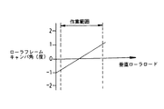
この構造によって、正と負の間で変わるキャンバ角が形成される。このキャンバ角は、機械の鉛直中心線52に垂直である仮定水平軸線58と、第一及び第二のガイドローラの回転軸線54、56との間の角度として定義される。回転軸線54、56のそれぞれは、仮定水平軸線58に対してキャンバ角“C”を形成する。角度“C”は、0.05度から2.0度の範囲内であることが好ましい。車台構造の殆どの従前の設計では、正のキャンバ角を形成するように構成されており、図5のグラフチャートに示されている。このような一定の正のキャンバ角によって、トラックチェーン組立体42は機械10の外側の方向に向かって付勢されて、トラックリンク44は、ガイドローラ34、36の一方側に進む。これによってガイドローラ34、36のトレッド部分60上に図7に示されたのと同様の摩耗パターンを形成する。
【0008】
キャンバ角が負の角と正の角との間を変わる車台構造14では、図6のグラフチャートに示されているように、トラックガイドローラの摩耗寿命は延びる。このことは、図8に示されており、本発明によってトラックリンク44は、ほぼ50%の作業時間、ローラ34、36の外側のフランジ62に対してスラストし、作動時間の残りの50%、内側フランジ64に対してスラストすることになる。
これによってトレッド部分60の望ましい摩耗パターンを作り出し、トレッド部分60のほぼ全幅が利用される。図7におけるロール36、38の最初の摩耗していない表面を点線66で示す。図7に示されているように、従来技術の車台における最初の表面66の一部分68は用いられることはない。
図9と図10を詳細に参照すると、ローラ36、38とトラックリンク44との間に、ある摩耗パターンがあることがわかる。図9は、従来の車台構造の一般的な摩耗パターンを示しており、ローラフレーム組立体は互いにほぼ平行に維持される。この摩耗パターンでは、摩耗がローラとリンクの全幅にほぼ沿って発生していることを示している。図10は、本発明を組み入れる車台構造14のローラ36、38とリンク44との間の典型的な摩耗パターンを示している。この摩耗パターンは、例えば機械が前方に進行するときに生じる第一の接触領域78におけるローラ36、38とリンク44との間の摩耗を示している。機械が反対方向に作動するとき、ローラフレーム組立体22、24が平行でないために、トラックチェーン組立体42は、ローラ36、38をリンク44の反対側に押しつける。次いで、第二の接触領域80においてローラ36、38とリンク44との間に摩耗が生じる。ローラ36、38とリンク44の間の接触表面が摩耗して凹凸形状になるので、リンク44がローラ36、38内で前後に動くとき、摩耗表面は、100%はまらない。これにより、車両10が前後に操作されるために分離した接触領域78、80となり、最終的にローラ36、38とリンク44の寿命を延ばすことになる。ローラ36、38が凹部形状82で最初に新しく製造され、リンク44が凸上形状84で新しく製造されているならば、この摩耗寿命をさらに高めることができる。ローラとリンクの現在の設計では、平坦な(円筒形)接触表面を用いる。
【0009】
図面と前述の詳細な記載を参照して、本発明のトラックタイプの車台構造14は、所定の車台部品の摩耗寿命を延ばすのに特に有効である。トラックローラフレーム組立体22、24が“トウイン”或いは“トウアウト”のいずれかを有している状態で、トラックリンク44は、機械10が前方向に進んでいるときに左右部分でローラ36、38と接触する。車両が反対方向に変更するときに、車台構造14が平行ではないために、リンク44をローラ36、38の反対側に押しつけ、ローラ36、38との間の分離した摩耗領域に移行させる。車両が方向を変えるときに、ローラ36、38内でのリンク44の前後の移動によって、リンク44とローラ36、38との間に少なくとも2つの分かれた別個の摩耗領域が作り出される。これにより、ローラ36、38とリンク44との間の接触圧が増大するときでも、これらの車台部品の摩耗寿命は長くなる。先のテストでは、接触圧と摩耗率との間には線形関係はないことがわかった。
別の実施例では、キャンバ角が正と負の間で変わることを利用する状態で、車台部品、特にローラ36’、38’の摩耗寿命が同様に長くなる。機械10が作動するとき、キャンバ角は、負から正に変化し、リンク44は、トレッド部分60上を進み、内側フランジ64、或いは、外側フランジ62のいずれかに近接する。リンク44は、キャンバ角が負から正に変化するときに、外側フランジ62と内側フランジ64との間を前後に進む。これは、ローラトレッド部分60の全幅を用い、車台部品の有効な摩耗寿命を延ばす。
【0010】
本発明の他の態様、目的及び利点は、図面、発明の記載及び請求の範囲から得ることができる。
【図面の簡単な説明】
【図1】本発明を組み入れたトラックタイプ機械の概略的な側図である。
【図2】図1の線2─2にほぼ沿った平面図である。
【図3】図2と類似した、本発明の別の実施例を示す平面図である。
【図4】本発明の他の実施例を表すトラックタイプの機械のメインフレームと車台構造組立体の実際の立面図である。
【図5】従来技術のトラックタイプ機械の正のキャンバ角を表すグラフチャートである。
【図6】本発明の負のチャンバ角を表すグラフチャートである。
【図7】先行技術の車台組立体の摩耗パターンを表すトラックローラの平面図である。
【図8】本発明を組み入れる車台組立体の摩耗パターンを表すトラックローラの平面図である。
【図9】先行技術の車台構造の摩耗パターンを表すトラックローラと、噛み合うトラックリンクの部分的に断面になった前面図である。
【図10】図9に類似しているが、本発明を組み入れた車台構造の摩耗パターンを表すトラックローラと噛み合うトラックリンクの、一部断面になった前面図である。
【符号】
10 トラックタイプ機械
12 メインフレーム
14 車台構造
16 第一側部
18 第二側部
20 中心線
22、24 トラックローラフレーム組立体
26 支持構造
32、34 アイドラーホイール
36、38 トラックガイドローラ
40 駆動スプロケットホイール
42 トラックチェーン組立体
44 トラックリンク
48、50 回転軸線
52 中心線
54、56 回転軸線[0001]
[Industrial application fields]
The present invention generally relates to a chassis structure for a truck-type machine. More particularly, the present invention relates to an improved chassis structure that increases the wear life of a given chassis component.
[0002]
[Prior art]
Current and previous designs for truck-type machine chassis structures use design and manufacturing methods that require that each of the left and right track assemblies be parallel to each other. Reducing manufacturing and assembly errors keeps the left and right track assemblies parallel. This is done in the belief that excessive wear on the track guide components occurs when the track assembly is not maintained in a parallel relationship. However, with the left and right track assemblies held parallel, the track link supports the interlocking roller treads in a fairly precise position.
[0003]
[Problems to be solved by the invention]
As the mating surfaces of the link and roller wear, the contact surfaces exhibit a wear shape that fits precisely together. In this way, wear is generated over the entire contact surface between the link and the roller by continuously operating the movable chassis structure.
The present invention solves one or more of the problems discussed above.
[0004]
[Means for Solving the Problems]
In one aspect of the present invention, a truck-type machine includes a chassis structure that includes a main frame having a longitudinal centerline and first and second track roller frame assemblies that are spaced apart from and close to the main frame. And have. The chassis includes a plurality of first and second track guide rollers connected to each of the first and second roller frame assemblies. Each of the track guide rollers has a rotation axis that is not substantially perpendicular to the longitudinal centerline.
The rapid wear of the moving chassis parts of self-installed track type machines is the main concern of the owners and operators of these machines. Many different fixings have been suggested and tried to extend the wear life of the moving chassis parts. These include the use of various guards and shields, various types of replaceable roller treads, and rigid materials embedded in the roller treads and link surfaces. Some of these fixings have been successful to a limited extent, but most have not been feasible or economical.
The present invention provides a chassis structure that extends the wear life of a given moving part. This is achieved by having a worn wear surface of the moving parts having one or more wear passages during machine and chassis operation.
[0005]
【Example】
Referring to the drawings, a truck-
[0006]
Referring to FIGS. 1 and 2 in detail, each of the first
Referring to FIGS. 1 and 3 in detail, another embodiment of the present invention is shown. In this embodiment, the
[0007]
Referring to FIGS. 1 and 4 in detail, a second alternative embodiment of the present invention is shown.
In this embodiment, the main frame 12 'has a
This structure forms a camber angle that varies between positive and negative. This camber angle is defined as the angle between a hypothetical horizontal axis 58 that is perpendicular to the
[0008]
In the
This creates a desired wear pattern for the
Referring to FIGS. 9 and 10 in detail, it can be seen that there is a certain wear pattern between the
[0009]
With reference to the drawings and the foregoing detailed description, the truck-
In another embodiment, utilizing the change in camber angle between positive and negative, the wear life of the chassis parts, in particular the rollers 36 ', 38', is similarly increased. When the
[0010]
Other aspects, objects and advantages of the invention can be obtained from the drawings, the description of the invention and the claims.
[Brief description of the drawings]
FIG. 1 is a schematic side view of a track-type machine incorporating the present invention.
FIG. 2 is a plan view substantially along the line 2-2 in FIG.
FIG. 3 is a plan view similar to FIG. 2, showing another embodiment of the present invention.
FIG. 4 is an actual elevation view of a main frame and chassis structure assembly of a truck type machine representing another embodiment of the present invention.
FIG. 5 is a graph representing the positive camber angle of a prior art track type machine.
FIG. 6 is a graph showing a negative chamber angle according to the present invention.
FIG. 7 is a plan view of a track roller representing the wear pattern of a prior art chassis assembly.
FIG. 8 is a plan view of a track roller representing the wear pattern of a chassis assembly incorporating the present invention.
FIG. 9 is a partial cross-sectional front view of a track roller and a mating track link representing a wear pattern of a prior art chassis structure.
FIG. 10 is a front view, partially in section, of a track link similar to FIG. 9 but meshing with a track roller representing a wear pattern for a chassis structure incorporating the present invention.
[Code]
10
Claims (8)
前記第一ローラフレーム組立体に回転可能に接続された複数の第一のトラックガイドローラと、前記第二ローラフレーム組立体に回転可能に接続された複数の第二のトラックガイドローラと、を備え、前記第一及び第二のトラックガイドローラの各々は、前記長手方向の中心線に対し垂直な線に対して傾斜した、前記ローラフレーム組立体に対する回転軸線を有していることを特徴とするトラックタイプ機械。A main frame having a first and second side portions and a longitudinal centerline, and parallel first and second parallel spaced apart from each of the first and second side portions of the main frame. A truck-type machine comprising: a track roller frame assembly; and a chassis structure including a support structure that connects each of the track roller frame assemblies to the main frame.
A plurality of first track guide rollers rotatably connected to the first roller frame assembly; and a plurality of second track guide rollers rotatably connected to the second roller frame assembly. The first and second track guide rollers each have an axis of rotation relative to the roller frame assembly that is inclined with respect to a line perpendicular to the longitudinal centerline. Track type machine.
前記第一側部に近接して、前記長手方向に延びる中心線にほぼ平行に配置された第一のトラックローラフレーム組立体と、
前記第二側部に近接して、前記長手方向に延びる中心線にほぼ平行に配置された第二のトラックローラフレーム組立体と、
前記第一トラックローラフレーム組立体に回転可能に接続された複数の第一トラックガイドローラと、
前記第二トラックローラフレーム組立体に回転可能に接続された複数の第二トラックガイドローラと、
を備え、前記第一及び第二トラックガイドローラのそれぞれは、前記長手方向に延びる中心線に対し垂直な線に対して傾斜した、前記第一及び第二トラックローラフレームに対する回転軸線を有していることを特徴とする車台構造。In a chassis structure of a truck-type machine having a main frame having first and second side portions and a center line extending in a longitudinal direction,
A first track roller frame assembly disposed proximate to the first side and substantially parallel to the longitudinally extending centerline;
A second track roller frame assembly disposed proximate to the second side and substantially parallel to the longitudinally extending centerline;
A plurality of first track guide rollers rotatably connected to the first track roller frame assembly;
A plurality of second track guide rollers rotatably connected to the second track roller frame assembly;
The provided, each of said first and second track guide rollers, is inclined with respect to a line perpendicular against the center line extending in the longitudinal direction, it has an axis of rotation for said first and second track roller frame A chassis structure characterized by that.
前記第一側部に近接して、前記長手方向に延びる中心線に対しほぼ平行に配置された第一のトラックローラフレーム組立体と、
前記第二側部に近接して、前記長手方向に延びる中心線に対しほぼ平行に配置された第二のトラックローラフレーム組立体と、
前記第一トラックローラフレーム組立体に回転可能に接続された複数の第一トラックガイドローラと、
前記第二トラックローラフレーム組立体に回転可能に接続された複数の第二トラックガイドローラと、を備え、
前記第一及び第二のトラックガイドローラのそれぞれは、前記長手方向に延びる中心線に対し垂直な線に対して傾斜した、前記第一及び第二ローラフレーム組立体に対する回転軸線を有しており、
前記第一及び第二のローラフレーム組立体のそれぞれに回転可能に接続されており、それぞれが、前記長手方向に延びる中心線に対し垂直な線に対して傾斜した回転軸線を有す るようになった、第一のトラックガイドアイドラーホイールを備えることを特徴とする車台構造。In the chassis structure of a truck type machine having a main frame having first and second side portions and a center line extending in the longitudinal direction ,
In proximity to the first side, the first track roller frame assembly that is substantially parallel to against the center line extending in the longitudinal direction,
In proximity to the second side, and a second track roller frame assembly wherein are arranged substantially parallel to against the longitudinally extending center line,
A plurality of first track guide rollers rotatably connected to the first track roller frame assembly;
A plurality of second track guide rollers rotatably connected to the second track roller frame assembly,
Wherein each of the first and second track guide rollers, is inclined with respect to a line perpendicular against the center line extending in the longitudinal direction, it has an axis of rotation for said first and second roller frame assembly ,
Wherein are rotatably connected to each of the first and second roller frame assemblies, the so that each, which have a rotational axis which is inclined with respect to a line perpendicular to the center line extending in the longitudinal direction A chassis structure comprising a first track guide idler wheel .
Applications Claiming Priority (2)
| Application Number | Priority Date | Filing Date | Title |
|---|---|---|---|
| US08/292984 | 1994-08-19 | ||
| US08/292,984 US5752574A (en) | 1994-08-19 | 1994-08-19 | Track-type machine undercarriage |
Publications (2)
| Publication Number | Publication Date |
|---|---|
| JPH0867277A JPH0867277A (en) | 1996-03-12 |
| JP3694547B2 true JP3694547B2 (en) | 2005-09-14 |
Family
ID=23127105
Family Applications (1)
| Application Number | Title | Priority Date | Filing Date |
|---|---|---|---|
| JP20877695A Expired - Fee Related JP3694547B2 (en) | 1994-08-19 | 1995-08-16 | Truck type mechanical chassis |
Country Status (3)
| Country | Link |
|---|---|
| US (1) | US5752574A (en) |
| JP (1) | JP3694547B2 (en) |
| IT (1) | IT1280914B1 (en) |
Families Citing this family (13)
| Publication number | Priority date | Publication date | Assignee | Title |
|---|---|---|---|---|
| US6401847B1 (en) * | 1996-11-08 | 2002-06-11 | Case Corporation | Vehicle track undercarriage adjustment system |
| US6367827B1 (en) * | 1997-09-22 | 2002-04-09 | Schneider Hans Jun | Caterpillar board designed in particular for use on grass slopes |
| US20050035655A1 (en) * | 2003-08-13 | 2005-02-17 | Clark Equipment Company | Track with offset drive lugs and drive wheel therefore |
| US7552785B2 (en) | 2006-11-02 | 2009-06-30 | Clark Equipment Company | Suspension system for track vehicle |
| US7798260B2 (en) | 2007-08-22 | 2010-09-21 | Clark Equipment Company | Track vehicle having drive and suspension systems |
| WO2009128890A1 (en) * | 2008-04-14 | 2009-10-22 | Clark Equipment Company | Method of retaining structural transmission members of a tracked work vehicle |
| US8540038B1 (en) * | 2009-01-09 | 2013-09-24 | The United States Of America As Represented By The Secretary Of The Navy | Low profile omnidirectional vehicle |
| USD719588S1 (en) | 2012-06-29 | 2014-12-16 | Caterpillar Inc. | Undercarriage track system for mobile earthmoving machine |
| USD727974S1 (en) | 2012-06-29 | 2015-04-28 | Caterpillar Inc. | Undercarriage track roller for mobile earthmoving machine |
| US9409613B2 (en) * | 2014-01-14 | 2016-08-09 | Caterpillar Inc. | Track system for a machine |
| US11208164B2 (en) | 2018-10-05 | 2021-12-28 | Caterpillar Inc. | Spalling resistant track link and roller interface |
| US11584456B2 (en) | 2019-07-26 | 2023-02-21 | Caterpillar Global Mining Equipment Llc | Undercarriage assembly for a machine |
| US11919584B2 (en) * | 2020-01-28 | 2024-03-05 | Caterpillar Inc. | Flip-flop track rollers |
Family Cites Families (20)
| Publication number | Priority date | Publication date | Assignee | Title |
|---|---|---|---|---|
| FR523157A (en) * | 1920-08-28 | 1921-08-13 | Adolphe Kegresse | Mechanisms for the practical use of flexible tracks |
| US1683407A (en) * | 1923-02-09 | 1928-09-04 | Roadless Traction Ltd | Endless-track vehicle |
| US1480693A (en) * | 1923-03-17 | 1924-01-15 | Roadless Traction Ltd | Endless-track vehicle |
| US1515167A (en) * | 1923-04-17 | 1924-11-11 | Roadless Traction Ltd | Endless-track vehicle |
| US1725817A (en) * | 1925-02-25 | 1929-08-27 | Harnischfeger Corp | Flexible-tread truck |
| US1941011A (en) * | 1931-12-02 | 1933-12-26 | Int Harvester Co | Equalizer connection for track laying tractors |
| US2605146A (en) * | 1949-09-13 | 1952-07-29 | Firestone Tire & Rubber Co | Endless track landing gear for aircraft |
| US3278386A (en) * | 1964-08-14 | 1966-10-11 | James E French | Delay bed system for purification of nuclear fuel element purge stream |
| US3412821A (en) * | 1966-09-09 | 1968-11-26 | Gen Gas Light Co | Track for motorcycle |
| US3576226A (en) * | 1969-03-10 | 1971-04-27 | Caterpillar Tractor Co | Compensating linkage for crawler tractors |
| US3825088A (en) * | 1972-12-07 | 1974-07-23 | Caterpillar Tractor Co | Equalizer bar mounting for track-type vehicles |
| US3889769A (en) * | 1974-09-09 | 1975-06-17 | Caterpillar Tractor Co | Suspension arrangement for a track-type vehicle |
| US3980149A (en) * | 1975-05-12 | 1976-09-14 | Caterpillar Tractor Co. | Stress-relieved axle mounting for track-type vehicles |
| US4018295A (en) * | 1975-11-14 | 1977-04-19 | Caterpillar Tractor Co. | Vehicle equalizer bar mounting means |
| US4647116A (en) * | 1979-06-22 | 1987-03-03 | Riggers Manufacturing Co. | Crawler suspension system |
| JPS606829B2 (en) * | 1979-12-18 | 1985-02-20 | 株式会社小松製作所 | Tracked vehicle suspension system |
| US4324303A (en) * | 1980-02-05 | 1982-04-13 | Caterpillar Tractor Co. | Equalizer bar support assembly |
| US5409305A (en) * | 1992-08-17 | 1995-04-25 | Deere & Company | Undercarriage for a track laying vehicle |
| US5279377A (en) * | 1993-04-12 | 1994-01-18 | Caterpillar Inc. | Track-type vehicle undercarriage |
| US5333710A (en) * | 1993-11-24 | 1994-08-02 | Caterpillar Inc. | Undercarriage for track-type machine |
-
1994
- 1994-08-19 US US08/292,984 patent/US5752574A/en not_active Expired - Lifetime
-
1995
- 1995-08-16 JP JP20877695A patent/JP3694547B2/en not_active Expired - Fee Related
- 1995-08-17 IT IT95TO000689A patent/IT1280914B1/en active IP Right Grant
Also Published As
| Publication number | Publication date |
|---|---|
| ITTO950689A1 (en) | 1997-02-17 |
| IT1280914B1 (en) | 1998-02-11 |
| ITTO950689A0 (en) | 1995-08-17 |
| US5752574A (en) | 1998-05-19 |
| JPH0867277A (en) | 1996-03-12 |
Similar Documents
| Publication | Publication Date | Title |
|---|---|---|
| JP3443120B2 (en) | Undercarriage of covered type vehicle | |
| JP3694547B2 (en) | Truck type mechanical chassis | |
| US8287056B2 (en) | Lobed bushing for track assembly and track-type machine using same | |
| US6471307B2 (en) | Crawler belt type traveling system | |
| US20100072813A1 (en) | Crawler Tracks and Idlers for Crawler Tracks | |
| US6474754B1 (en) | Roller assembly for an undercarriage of a work machine | |
| US20160244111A1 (en) | Work vehicle | |
| JPH10157659A (en) | Track assembly and idler wheel in track assembly | |
| WO2018111496A1 (en) | Bushing for track assembly | |
| US3680929A (en) | Mid-pitch drive lug for track link of endless track | |
| US5333710A (en) | Undercarriage for track-type machine | |
| US5433515A (en) | Guide rollers for flexible drive belt | |
| US5462345A (en) | Resilient wheels with reinforcing rings | |
| US3860299A (en) | Endless track for vehicle | |
| JPH115573A (en) | Core bar for rubber crawler and rubber crawler using the same | |
| JP2000159160A (en) | Rubber crawler | |
| JPH0971271A (en) | Crawler running body | |
| CN112770961A (en) | Anti-spalling track link and track wheel interface | |
| JP2001097256A (en) | Protection structure of rubber-made crawler belt in caterpillar traveling apparatus | |
| WO1998016419A1 (en) | Load sharing wheel assembly for track laying vehicle | |
| JPH07315262A (en) | Elastic crawler | |
| JPH107041A (en) | Rubber crawler device | |
| JPH06247352A (en) | Structure of rubber crawler | |
| JP2002012174A (en) | Crawler type travel device | |
| JP2000118453A (en) | Rubber crawler |
Legal Events
| Date | Code | Title | Description |
|---|---|---|---|
| A977 | Report on retrieval |
Free format text: JAPANESE INTERMEDIATE CODE: A971007 Effective date: 20040817 |
|
| A131 | Notification of reasons for refusal |
Free format text: JAPANESE INTERMEDIATE CODE: A131 Effective date: 20040830 |
|
| A521 | Request for written amendment filed |
Free format text: JAPANESE INTERMEDIATE CODE: A523 Effective date: 20041115 |
|
| TRDD | Decision of grant or rejection written | ||
| A01 | Written decision to grant a patent or to grant a registration (utility model) |
Free format text: JAPANESE INTERMEDIATE CODE: A01 Effective date: 20050613 |
|
| A61 | First payment of annual fees (during grant procedure) |
Free format text: JAPANESE INTERMEDIATE CODE: A61 Effective date: 20050627 |
|
| R150 | Certificate of patent or registration of utility model |
Free format text: JAPANESE INTERMEDIATE CODE: R150 |
|
| FPAY | Renewal fee payment (event date is renewal date of database) |
Free format text: PAYMENT UNTIL: 20080701 Year of fee payment: 3 |
|
| FPAY | Renewal fee payment (event date is renewal date of database) |
Free format text: PAYMENT UNTIL: 20090701 Year of fee payment: 4 |
|
| FPAY | Renewal fee payment (event date is renewal date of database) |
Free format text: PAYMENT UNTIL: 20100701 Year of fee payment: 5 |
|
| FPAY | Renewal fee payment (event date is renewal date of database) |
Free format text: PAYMENT UNTIL: 20110701 Year of fee payment: 6 |
|
| FPAY | Renewal fee payment (event date is renewal date of database) |
Free format text: PAYMENT UNTIL: 20110701 Year of fee payment: 6 |
|
| FPAY | Renewal fee payment (event date is renewal date of database) |
Free format text: PAYMENT UNTIL: 20120701 Year of fee payment: 7 |
|
| FPAY | Renewal fee payment (event date is renewal date of database) |
Free format text: PAYMENT UNTIL: 20130701 Year of fee payment: 8 |
|
| LAPS | Cancellation because of no payment of annual fees |