JP3694477B2 - Animation trajectory compression method and decompression method using linear approximation method and apparatus thereof - Google Patents
Animation trajectory compression method and decompression method using linear approximation method and apparatus thereof Download PDFInfo
- Publication number
- JP3694477B2 JP3694477B2 JP2001357514A JP2001357514A JP3694477B2 JP 3694477 B2 JP3694477 B2 JP 3694477B2 JP 2001357514 A JP2001357514 A JP 2001357514A JP 2001357514 A JP2001357514 A JP 2001357514A JP 3694477 B2 JP3694477 B2 JP 3694477B2
- Authority
- JP
- Japan
- Prior art keywords
- key
- trajectory
- animation
- breakpoints
- animation trajectory
- Prior art date
- Legal status (The legal status is an assumption and is not a legal conclusion. Google has not performed a legal analysis and makes no representation as to the accuracy of the status listed.)
- Expired - Fee Related
Links
Images


Classifications
-
- G—PHYSICS
- G06—COMPUTING; CALCULATING OR COUNTING
- G06T—IMAGE DATA PROCESSING OR GENERATION, IN GENERAL
- G06T13/00—Animation
-
- G—PHYSICS
- G06—COMPUTING; CALCULATING OR COUNTING
- G06T—IMAGE DATA PROCESSING OR GENERATION, IN GENERAL
- G06T9/00—Image coding
- G06T9/001—Model-based coding, e.g. wire frame
-
- H—ELECTRICITY
- H04—ELECTRIC COMMUNICATION TECHNIQUE
- H04N—PICTORIAL COMMUNICATION, e.g. TELEVISION
- H04N19/00—Methods or arrangements for coding, decoding, compressing or decompressing digital video signals
- H04N19/20—Methods or arrangements for coding, decoding, compressing or decompressing digital video signals using video object coding
- H04N19/25—Methods or arrangements for coding, decoding, compressing or decompressing digital video signals using video object coding with scene description coding, e.g. binary format for scenes [BIFS] compression
-
- H—ELECTRICITY
- H04—ELECTRIC COMMUNICATION TECHNIQUE
- H04N—PICTORIAL COMMUNICATION, e.g. TELEVISION
- H04N19/00—Methods or arrangements for coding, decoding, compressing or decompressing digital video signals
- H04N19/20—Methods or arrangements for coding, decoding, compressing or decompressing digital video signals using video object coding
- H04N19/27—Methods or arrangements for coding, decoding, compressing or decompressing digital video signals using video object coding involving both synthetic and natural picture components, e.g. synthetic natural hybrid coding [SNHC]
-
- H—ELECTRICITY
- H04—ELECTRIC COMMUNICATION TECHNIQUE
- H04N—PICTORIAL COMMUNICATION, e.g. TELEVISION
- H04N19/00—Methods or arrangements for coding, decoding, compressing or decompressing digital video signals
- H04N19/50—Methods or arrangements for coding, decoding, compressing or decompressing digital video signals using predictive coding
- H04N19/593—Methods or arrangements for coding, decoding, compressing or decompressing digital video signals using predictive coding involving spatial prediction techniques
Landscapes
- Engineering & Computer Science (AREA)
- Multimedia (AREA)
- Signal Processing (AREA)
- Physics & Mathematics (AREA)
- General Physics & Mathematics (AREA)
- Theoretical Computer Science (AREA)
- Processing Or Creating Images (AREA)
- Compression Or Coding Systems Of Tv Signals (AREA)
- Compression, Expansion, Code Conversion, And Decoders (AREA)
Description
【0001】
【発明の属する技術分野】
本発明は、3次元グラフィックスモデルのアニメーションに係り、特にアニメーションに使用されるアニメーション軌跡(path)を、線形近似化の手法を用いて圧縮及び復元する装置、この装置で行われる圧縮及び復元方法、並びにこのためのデータのフォーマットに関する。
【0002】
【従来の技術】
グラフィックスに基づいた3次元アニメーション(animation;動画)の場合、3次元モデルで表現されたオブジェクト(客体)のアニメーションに対する空間上の動き、回転、モデル自体のモルフィング(morphing)、色の変移などを表現するためにインターポレータ(interpolator)が使用される。
【0003】
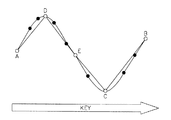
図1は、一般の3次元アニメーションにおけるアニメーション軌跡を説明するための図であって、縦軸はキー値(KEY_VALUE)を、横軸はキー(KEY)を各々示す。
図1に示すアニメーション軌跡20は3次元モデル10のアニメーションの痕跡を表現したものである。このアニメーション情報の軌跡(アニメーション軌跡)20は、図1に示すように経時的に変化する2次元曲線の形態を有する。アニメーション軌跡20を表現する方式は種々あり、このような様々な方式は1989年に、Prentice Hall社から出版された「Fundamentals of Digital Image Processing」の第9章に開示されている。
【0004】
インターポレータによる表現では図1に示すような曲線状のアニメーション軌跡20を複数個のセグメント(分節)を用いて直線状に分けて表現することができる。このような表現において必要な情報は、各直線のブレークポイント(break point;分節点)または頂点である。
ここで、前記「ブレークポイント」または「頂点」は、図1に示すアニメーション軌跡20において黒色の点「●」で表されている。線形補間(または挿入)(Linear Interpolation)の手法を用いると、これらの各ブレークポイントから元の曲線を復元することができる。
【0005】
図2は、仮想現実モデリング言語(VRML:Vertual Reality Modeling Language)、またはMPEG(Moving Picture Expert Group)−4で使用されるアニメーション軌跡の表現例(Scalar Interpolator)を示す図である。ここで処理されるべき情報はキー及びキー値を含み、与えられた情報から前記線形補間作業が行われる。
【0006】
インターポレータの種類には大別して6種、すなわち、スカラーインターポレータ、位置インターポレータ、回転インターポレータ、座標インターポレータ、法線インターポレータ及び色インターポレータがある。
ここで、スカラーインターポレータは、図2に示すように表現することができる。各インターポレータの種類、特徴及び機能を次の表1に示す。表1に示すように、与えられたキーとこれらのキーによるキー値の集合という点において、これらのインターポレータは相等しい。
【0007】
【表1】

図3は、3次元アニメーションのデータ形式を説明するための図面であって、エンコーダ30、デコーダ40及び3次元アニメーションファイルフォーマット50を示す。
ここで、エンコーダ30からデコーダ40に出力される3次元アニメーションファイルフォーマット50は、モデルデータ、アニメーションデータ、属性、ビデオ/テクスチャー及びサウンドで構成されている。
【0009】
図3を参照すると、インターポレータは3次元アニメーション軌跡を効率よく表現するアニメーションデータに該当する。VRML/MPEG−4で表現される3次元アニメーションデータは、図3に示すような情報で構成される。従来のオーディオ、ビデオ、3次元モデルに対しては、標準化された圧縮技術が提供されていたが、アニメーション軌跡を決定するインターポレータの場合には、表現中心の汎用圧縮技術のみが提供されている。オーディオ/ビデオを除いたアニメーションの場合、アニメーション軌跡のデータ量は、3次元モデルと共にデータの大部分を占めることになる。したがって、3次元モデルの圧縮技術と共にアニメーション軌跡に対する圧縮技術が必須である。MPEG−4BIFS(Binary Format for Scene)でアニメーションに対する基本的な量子化/圧縮方法を提供するが、これはインターポレータのための専用圧縮機術ではない汎用圧縮技術であって、圧縮性能が脆弱という問題点がある。これについては、2000年にニューヨークで開催されたマルチメディア及びエキスポに関する国際会議(International Conference onmultimedia and Expo)の会報に記載されている、Euee S.Jangによって発表された「3D Animation Coding:its History and Framework」で開示されている。
【0010】
図4(A)及び図4(B)は各々、前記アニメーション軌跡に対する従来の圧縮装置及び復元装置のブロック図であって、図4(A)に示す従来の圧縮装置はスカラー量子化部60を有して構成され、図4(B)に示す従来の復元装置はスカラー逆量子化部70を有して構成されている。
【0011】
図4(A)に示すスカラー量子化部60は、元のアニメーション軌跡がkey、key_value(ここで、keyはキーを、key_valueはキー値を各々示す。)の形で入力端子IN1を通して入力されてスカラー量子化され、このようにスカラー量子化された結果である符号化されたビットストリームは、出力端子OUT1を通して出力される。また、図4(B)に示すスカラー逆量子化部70は、符号化されたビットストリームを、入力端子IN2を通して入力され、復元されたアニメーション軌跡(key、key_value)の形のデータとして出力端子OUT2を通して出力する。
【0012】
従来のMPEG−4BIFSでのインターポレータの圧縮は、図4(A)に示すようにスカラー量子化を経て実行される。図4(A)に示す従来の圧縮過程は、インターポレータのみならず、BIFSでの圧縮が要求されるあらゆる要素にも共通して提供される方式である。図4(B)に示す従来の復元装置に入力された符号化されたビットストリームは、圧縮の順序を逆に実行することによりスカラー逆量子化部70を経てアニメーション軌跡が復元される。図4(A)及び図4(B)では、インターポレータから提供されるキー及びキー値等が各種類ごとの特性を考慮することなく同じ方式で圧縮されるので、充分な圧縮効果を発揮することができないという問題点がある。
【0013】
【発明が解決しようとする課題】
前記問題点を解決するために、本発明の第1の目的は、インターポレータ形式のアニメーションデータを効率よく圧縮して、迅速なデータの伝送及び記憶を可能にする、線形近似化の手法を用いたアニメーション軌跡の圧縮装置及びその方法を提供することにある。
【0014】
また、本発明の第2の目的は、圧縮されたアニメーション軌跡のデータを効率的に復元することができるアニメーション軌跡の復元装置及びその方法を提供することにある。
【0015】
更に、本発明の第3の目的は、アニメーション軌跡データの圧縮に用いられるアニメーション軌跡に対する圧縮用データフォーマットを提供することにある。
【0016】
【課題を解決するための手段】
前記第1の目的を達成するために、本発明に係る第1の態様は、アニメーション軌跡から所定数のブレークポイントを抽出し、前記抽出されたブレークポイントに対応するキー及びキー値を出力する補間分析部と、前記補間分析部から出力されるキーを符号化するキー符号化部と、前記補間分析部から出力されるキー値を符号化するキー値符号化部と、前記キー符号化部、及びキー値符号化部で符号化されたキー、及びキー値を、エントロピー符号化して符号化されたビットストリームとして出力するエントロピーエンコーダとを具備することを特徴とするアニメーション軌跡の圧縮装置を提供する。
【0017】
本発明に係る第2の態様は、前記第1の態様において、補間分析部が、元のアニメーション軌跡のブレークポイントの中から抽出された所定数のブレークポイントによって得られるアニメーション軌跡と、元のアニメーション軌跡との差を最小化させる方向に、前記ブレークポイントの個数を決定することを特徴とするアニメーション軌跡の圧縮装置を提供する。
また、本発明に係る第3の態様は、前記第1の態様において、キー符号化部が、補間分析部から入力されたキーを、差分パルス符号変調(DPCM:Differential Pulse Coding Modulation)量子化方式によって符号化することを特徴とするアニメーション軌跡の圧縮装置を提供する。
更に、本発明に係る第4の態様は、前記第1の態様において、キー値符号化部が、補間分析部から入力されたキー値を、差分パルス符号変調(DPCM)量子化方式によって符号化することを特徴とするアニメーション軌跡の圧縮装置を提供する。
【0018】
また、本発明に係る第5の態様は、前記第1の態様において、補間分析部が、元のアニメーション軌跡の両端の点を出発点として、各ブレークポイントの中から元のアニメーション軌跡との差が最小となるように近似化された軌跡を示すブレークポイントを探し出し、近似化されたアニメーション軌跡が前記元のアニメーション軌跡と近づくまでこのような過程を繰り返すことを特徴とするアニメーション軌跡の圧縮装置を提供する。
更に、本発明に係る第6の態様は、前記第5の態様において、前記ブレークポイントが、元のアニメーション軌跡と、近似化されたアニメーション軌跡との面積の差を最小化させるように決定されることを特徴とするアニメーション軌跡の圧縮装置を提供する。
そして、本発明に係る第7の態様は、前記第3または第4の態様において、前記差分パルス符号変調(DPCM)量子化方式が、現在値と直前値との差を符号化する、あるいは、直前値と更にその直前値との差に直前値を足した近似値と、現在値との差を符号化することを特徴とするアニメーション軌跡の圧縮装置を提供する。
【0019】
前記第2の目的を達成するために、本発明に係る第8の態様は、符号化されたビットストリームが入力されると、このビットストリームをエントロピーデコーディングするエントロピーデコーダと、前記エントロピーデコーディングされた結果が入力されると、そのキーを復号化するキー復号化部と、前記エントロピーデコーディングされた結果が入力されると、そのキー値を復号化するキー値復号化部と、前記キー復号化部、及びキー値復号化部によって復号化されたキー、及びキー値に基づく線形補間の手法によって、空のキー値を求めて元のアニメーション軌跡に復元する補間復元部とを具備することを特徴とするアニメーション軌跡の復元装置を提供する。
【0020】
本発明に係る第9の態様は、前記第8の態様において、キー復号化部が、エントロピーデコーダから入力されたデコーディングされた結果を、差分パルス符号変調(DPCM)逆量子化方式によって復号化することを特徴とするアニメーション軌跡の復元装置を提供する。
また、本発明に係る第10の態様は、前記第8の態様において、キー値復号化部が、エントロピーデコーダから入力されたデコーディングされた結果を、差分パルス符号変調(DPCM)逆量子化方式で復号化することを特徴とする請求項8に記載のアニメーション軌跡の復元装置を提供する。
【0021】
前記第1の目的を達成するために、本発明に係る第11の態様は、元のアニメーション軌跡から所定数のブレークポイントを抽出する段階と、前記抽出されたブレークポイントを用いてキー及びキー値を抽出し、これらを符号化する段階と、前記符号化されたキー及びキー値をエントロピー符号化し、これらを符号化してビットストリームを求める段階とを具備することを特徴とするアニメーション軌跡の圧縮方法を提供する。
【0022】
前記第2の目的を達成するために、本発明に係る第12の態様は、符号化されたビットストリームが入力されると、これをエントロピーデコーディングする段階と、前記エントロピーデコーディングされた結果から、キー及びキー値を復号化する段階と、前記復号化されたキー及びキー値に基づく線形補間の手法によって空のキー値を求め、元のアニメーション軌跡を復元する段階とを具備することを特徴とするアニメーション軌跡の復元方法を提供する。
【0023】
前記第3の目的を達成するために、本発明に係る第13の態様は、アニメーション軌跡の各ブレークポイントのx、y、z座標に対応するキー値の中で、どの座標軸のキー値が選択されたかを示すアレイ型キーフラグと、各ブレークポイントでx、y、z座標に対応するキー値の中から少なくとも1つのキー値が選択されることを示すアレイ型キーと、各ブレークポイントで選択されたキー値を示すアレイ型キー値とを具備することを特徴とするアニメーション軌跡が符号化されたビットストリームのデータフォーマットを提供する。
【0024】
本発明に係る第14の態様は、前記第12の態様において、X、Y、Z座標軸に対応するキー値の最小値と、X、Y、Z座標軸に対応する、キー値の最大値とを更に含んで構成されることを特徴とするアニメーション軌跡が符号化されたビットストリームのデータフォーマットを提供する。
また、本発明に係る第15の態様は、前記第12の態様において、アレイ型キーフラグが、M(M≦n、nは元のキーの個数)個のデータを含むことを特徴とするアニメーション軌跡が符号化されたビットストリームのデータフォーマットを提供する。
更に、本発明に係る第16の態様は、前記第12の態様において、前記アレイ型キーが、M(M≦n、nは元のキーの個数)個のデータを含むことを特徴とするアニメーション軌跡が符号化されたビットストリームのデータフォーマットを提供する。
そして、本発明に係る第17の態様は、前記第12の態様において、前記キー値は、x軸に対するp(p≦n、nはキーの個数)個の第1キー値、y軸に対するq(q≦n、nはキーの個数)個の第2キー値及びz軸に対するr(r≦n、nはキーの個数)個の第3キー値を具備することを特徴とするアニメーション軌跡が符号化されたビットストリームのデータフォーマットを提供する。
【0025】
前記第3の目的を達成するために、本発明に係る第18の態様は、(a)元のアニメーション軌跡の上にあるブレークポイントの中から両端の2個のブレークポイントを選択する段階と、(b)前記選択された両端のブレークポイントを除いた残りのブレークポイントの中から1個のブレークポイントを選択する段階と、(c)前記選択されたブレークポイントを用いて、前記選択されたブレークポイントを除いた残りのブレークポイントのキー値を補間する段階と、(d)前記選択されたキー値、及び前記補間されたキー値に基づいて近似化された軌跡を形成し、元のアニメーション軌跡と前記近似化されたアニメーション軌跡との差が最小であるアニメーション軌跡を選択し、前記選択されたアニメーション軌跡に対応するブレークポイントを選択する段階と、(e)前記選択されたブレークポイントを除いた残りのブレークポイントの中から1個のブレークポイントを選択した後、前記(c)段階を再び繰り返し、前記元のアニメーション軌跡と前記近似化されたアニメーション軌跡との差が許容差よりも小さくなるまで繰り返す段階とを含むことを特徴とするアニメーション軌跡のブレークポイント抽出方法を提供する。
【0026】
本発明に係る第19の態様は、前記第18の態様において、元のアニメーション軌跡と前記近似化されたアニメーション軌跡との差が、元のアニメーション軌跡、及び近似化された軌跡によって形成される台形、またはネジレ台形の面積の和で表現されることを特徴とするアニメーション軌跡のブレークポイント抽出方法を提供する。
本発明に係る第20の態様は、前記第18の態様において、元のアニメーション軌跡と前記近似化されたアニメーション軌跡との差が、回転インターポレータの場合に、元のアニメーション軌跡に対する回転変換と前記近似化された軌跡に対する回転変換との差である差分回転変換における差分回転角として定義されることを特徴とするアニメーション軌跡のブレークポイント抽出方法を提供する。
【0027】
なお、本発明では、VRML/MPEG−4で一般に使用されているインターポレータ表現を用いることができる。このインターポレータが使用される分野は、主にオンラインコンピューターゲーム、アニメーション広告である。
【0028】
【発明の実施の形態】
以下、添付した図面に基づき本発明を詳細に説明する。
図5(A)は本発明に係るアニメーション軌跡の圧縮装置のブロック図である。図5(A)に示すように、本発明に係るアニメーション軌跡の圧縮装置は、補間分析部80、キー符号化部82、キー値符号化部84及びエントロピーエンコーダ86を含んで構成される。また、図5(B)は本発明に係るアニメーション軌跡の復元装置のブロック図である。図5(B)に示すように、本発明に係るアニメーション軌跡の復元装置は、エントロピーデコーダ90、キー復号化部92、キー値復号化部94及び補間復元部96を含んで構成される。
【0029】
図5(A)に示す本発明に係るアニメーション軌跡の圧縮装置に含まれる補間分析部80は、符号化するキーとキー値とを選定するものであり、各種インターポレータの特性を考慮して設計することができる。詳細な説明は後述する。
図6は、図5(A)に示す本発明に係るアニメーション軌跡の圧縮装置において、本発明に係る望ましい1実施形態のブロック図である。本発明に係る1実施形態のアニメーション軌跡の圧縮装置は、図6に示すように、正規化部100及びブレークポイント最小化部102を含む補間分析部80、差分パルス符号変調(DPCM:Differential Pulse Coding Modulation)量子化部104を含むキー符号化部82、DPCM量子化部106を含むキー値符号化部84及びエントロピーエンコーダ86を含んで構成されている。
【0030】
図7は、図5(B)に示す本発明に係るアニメーション軌跡の復元装置において、本発明に係る望ましい1実施形態のブロック図である。本発明に係る1実施形態のアニメーション軌跡の復元装置は、図7に示すように、エントロピーデコーダ90、DPCM逆量子化部126を含むキー復号化部92、DPCM逆量子化部128を含むキー値復号化部94及びキー及びキー値復元部95を含む補間復元部96を有して構成されている。
【0031】
補間分析部80(図5(A)、図6)の入力として提供されるインターポレータ表現は、キー(K)とキー値(KV)とを含む。図6に示す本発明に係る1実施形態のアニメーション軌跡の圧縮装置において、補間分析部80は、入力端子IN3を通して入力されたアニメーション軌跡が最小のブレークポイントで表示されるようにブレークポイントの個数を調節するようになっている。アニメーション軌跡に対する元のブレークポイントの個数がN個であれば、補間分析部80を経て出るブレークポイントの個数はM(M≦N)個に調整される。すなわち、補間分析部80は、入力端子IN3を通して入力された元のアニメーション軌跡からブレークポイントを抽出する役割を果たす。
【0032】
インターポレータでは、キーとキー値は各々正規化して使用される。このため、正規化部100(図6)は、入力端子IN3を通して入力した元のアニメーション軌跡で、キー及びキー値を各々正規化してブレークポイント最小化部102に出力する。VRMLによって支持されるkeyは0以上1以下の値を有する。
【0033】
補間分析部80(図6)がブレークポイントの個数を調整する方式としては、調整されたブレークポイントによって形成されるアニメーション軌跡と元のアニメーション軌跡との差を最小化させる方向でブレークポイントの個数を決定する方式を採用することができる。このとき、ブレークポイント最小化部102は、正規化部100から出力される、正規化されたキー及びキー値から最小限のブレークポイントが抽出されるようにする。例えば、位置インターポレータの場合、実際の軌跡と、補間分析部80を通して決定される量子化された軌跡との間に最小の面積誤差が生じるようにブレークポイントを決定することができる。
【0034】
一方、図6に示すブレークポイント最小化部102で実行される線形近似化法を用いたブレークポイントの抽出方法について説明すると次の通りである。
図8から図15は、線形近似化の手法を用いたブレークポイント抽出の本発明に係る望ましい1実施形態を説明するための図面であって、アニメーション軌跡の上に表示された各点はブレークポイントを示す。図8は元のアニメーションの軌跡を表し、図9は軌跡の両端の点A、Bを探す状態を表し、図10は元の軌跡と最も近いブレークポイントを選択する過程を表し、図11は1次抽出されたブレークポイントA、B、C(図中、白抜きの点「○」で示す)を表し、図12は元の軌跡と近い2次ブレークポイントを抽出する過程を表し、図13は2次抽出されたブレークポイントA、B、C、D(図中、白抜きの点「○」で示す)を表し、図14は3次抽出されたブレークポイントA、B、C、D、Eを表し、図15は4次抽出されたブレークポイントA、B、C、D、E、F(図中、白抜きの点「○」で示す)を表す。
【0035】
与えられた元のアニメーション軌跡が図8に示すような軌跡である場合、元のアニメーション軌跡のブレークポイント(N個)の中で、元の軌跡との間の差が最小化となるような近似化された軌跡を示すブレークポイント(M個、2≦M≦N)を探し出す過程が、両端の点A、Bを出発点として繰り返される。このような過程を、図9から図15に示す。その際、前記ブレークポイントの抽出は、前記のように近似化された軌跡が元の軌跡に充分に近い状態であると判断されるまで反復される。
【0036】
以下、元のアニメーション軌跡と、近似化されたアニメーション軌跡との面積の差を用いて、近似化された軌跡と実際の軌跡との間の差を求める方法について、添付した図面を参照しながらに説明する。
図16は、実際のアニメーション軌跡200と近似化されたアニメーション軌跡210との差を求める方法を説明するための図面である。図16を参照すると、前記両者の軌跡の差は、台形またはネジレ台形で表現されている。下記式(1)は図16に示す台形(D TRAPEZOID:台形D)の面積を求める公式であり、下記式(2)は図16に示すネジレ台形(TWISTED_TRAPEZOID)の面積を求める公式である。したがって、実際のアニメーション軌跡200と近似化されたアニメーション軌跡210との差は、台形とネジレ台形の面積の和で表現され、これらの台形の面積の和(図16中、破線で囲んだ範囲内の台形またはネジレ台形の和)が下記式(3)で表される前記両者の軌跡の面積差DAとなる。
【0037】
【数1】
【数2】
【数3】
本発明にあっては、前記式(3)で表される面積差DAを最小化させる方向にブレークポイントを抽出するものである。前述したように、ブレークポイント最小化部102が、前記ブレークポイントを抽出するようになっている。すなわち、図6に示す補間分析部80を経由して、アニメーション軌跡の基本的ブレークポイントが抽出される。
なお、無損失処理が必要な場合には、前記抽出されたブレークポイントの個数(M)は元のブレークポイントの個数と同一であってもよい。
【0041】
また、位置インターポレータの場合、キー値がX、Y、Z座標軸の3次元空間上の位置を表示するために、アニメーション軌跡は、X、Y、Z座標軸上の3つの曲線で表される。図6の補間分析部80は、前記座標軸の各軸で独立してブレークポイントの抽出を行なうことができる。その際、前記座標軸の各軸ごとにブレークポイントは異なる。以下に示す表2は、8つのブレークポイントP0、P1、P2、P3、P4、P5、P6、P7を有する実際の軌跡を、補間分析部80を経由させることによって、新たなブレークポイントを抽出した結果を示す。
【0042】
【表2】
表2において、key_flagはキーフラグを、kvx、kvy及びkvzは各々、座標軸X、Y、Zに対応するキー値を示す。
ここで、「0」は各ブレークポイントで当該軸に対応するキー値が選択されたこと(例えば、ブレークポイントP0に対してX軸キー値kvxが選択されたこと)を意味し、「X」は各ブレークポイントで当該軸に該当するキー値が選択されなかったことを意味する。キーフラグは各ブレークポイントでx、y、z座標に対応するキー値の中で、どの軸のキー値が選択されたかを示し、例えば、「7」はあらゆる軸のキー値が選択されたことを意味し、「6」はx軸のキー値kvxが選択されず、残りは選択されたことを意味する。
【0044】
表2に示すように、ブレークポイントP1、P3、P6は、X、Y、Zの座標軸に対応するキー値の中からいずれのキー値も選択されず(kvx、kvy、kvzが「X」で示されている)、不要なブレークポイントであると判定されたものである(キーフラグにおいて、「−」と表示されている)。
【0045】
また、表2のP0、P7は、軌跡の両端の点であり、あらゆる軸でブレークポイントとして抽出された場合を示し、P2はX軸ではブレークポイントとして選択されなかったが、他の軸ではブレークポイントとして選択されたものである。したがって、図6の補間分析部80では、元の8つのブレークポイントの代わりに、5つのブレークポイントに対応するキーが選定され、この選定されたブレークポイントに対応して各軸のキー値が決定される。表2ではキーが5つ、キー値が11個必要な場合が示されている。このようなキーとキー値との対応関係は、付加的に伝送されるキーフラグ(key_flag)によって表現される。このような表現によって、キーとキー値の個数は、実際の軌跡に対応する4×8=32から、16個のキーとキー値、更に1つの付加的なキーフラグ(key_flag)に減少することになる。本発明にあっては、このような過程を通して表現の簡素化が実行される。
【0046】
図24から図29は、球面の線形近似化法を用いたブレークポイント抽出の、本発明に係る望ましい更に他の実施形態を説明するための図面であって、回転インターポレータでブレークポイント(または「キーフレーム」とも言う。)を減少させる方法に関するものである。
【0047】
図24は元のアニメーション軌跡の上で、各時間でのn+1個の各ブレークポイントにおけるキー値(Q0、Q1、Q2、…、Qn)を示しており、これらのキー値に対応する点を黒色の点(図中「●」)で示す。図25に示すように、まずアニメーション軌跡の上にある各ブレークポイントの中から両端の2個のブレークポイント(Q0、Qn)を選択する。このように選択された点を白抜きの点(図中「○」)で示す。
【0048】
図26は、前記のように選択された両端のブレークポイントを除いた残りのブレークポイントの中から1個のブレークポイント(3番目のブレークポイント)を選択する過程を示す図である。この際、3番目のブレークポイント候補を選択する方法は全部でn−1種ある。図26は、2種の候補(Q1、Qk)選択した例を示している。そして、前記n−1種の候補の各々に対して選択された合計で3つのブレークポイントを用いて、選択されなかったブレークポイントのキー値を、球面の線形補間法によって補間する。元のアニメーション軌跡を、この補間法によって求めたn−1種のアニメーション軌跡の候補と各々比較してアニメーション軌跡の誤差が最小となるアニメーション軌跡を選択し、このアニメーション軌跡の選択によって、n−1種のブレークポイント候補の中から選択されたアニメーション軌跡の候補に対応したブレークポイントを選択する。図27では、その1例として候補2の軌跡が選択されたことを示している。軌跡間の誤差は平均誤差Emを用いて求められる。
【0049】
そして、図28に示すように、図27で選択された3つのブレークポイントを除いた残りのブレークポイントの中から1個のブレークポイントを選択した後、前述した図26、図27に示すような過程を実行して4番目のブレークポイントを選択する。一例として図29は候補1の軌跡が選択されたことを示す。そして、図28と関連したブレークポイント選択過程を、平均誤差が許容誤差より小さくなるまで反復して元の軌跡のブレークポイントの個数と同一、あるいは元の軌跡のブレークポイントの個数よりも少ない数のブレークポイントを抽出する。
【0050】
また、前述した平均誤差Emは、次のようにして求めることができる。まず、量子化誤差を、元のアニメーション軌跡に対する回転変換と、復元されたアニメーション軌跡に対する回転変換との差の差分回転変換での差分回転角として定義する。すなわち、下記記号(S1)は回転インターポレータのノードに属した1つのキー値を示し、これを復号化器で復元したキー値を下記記号(S2)で表す場合(但し、下記ベクトル(S3)は回転軸を示し、下記記号(S4)は回転量を示し、その範囲は下記記号(S5)を満たす。)、下記記号(S1)と下記記号(S2)とにより、3次元空間上の任意の位置ベクトル(S6)からベクトル(S7)及びベクトル(S8)への回転変換が行われるとき、生じる量子化誤差は下記ベクトル(S7)と下記ベクトル(S8)との差から求められる。この量子化誤差は下記式(E)で表される関係を成立させる。
ここで、下記ベクトル(S6)、ベクトル(S7)、ベクトル(S8)を四元数(quaternion)で表すと下記式(5)、(5´)で定義される。
【0051】
【数4】
![]()
【数5】
![]()
【数6】
![]()
【数7】
![]()
【数8】
![]()
【数9】
![]()
【数10】
![]()
【数11】
![]()
【数12】
![]()
【数13】
回転変換を示す前記(S1)と(S2)とを四元数で表現したものを、各々QとQ’とする場合、下記式(5)、(5´)が導出される。
【0062】
【数14】
前記式(5)、(5´)において、A*Bの形はAとBとの四元数乗算を表し、A*はAのコンジュゲートを意味する。前記式(5)、(5´)によって下記式(6)が導出される。
【0064】
【数15】
![]()
前記式(6)中、Q″は前記ベクトル(S7)とベクトル(S8)との回転変換関係を示す値であって下記式(7)で定義される。
【0066】
【数16】
![]()
前記式(7)より、前記ベクトル(S7)とベクトル(S8)との差分回転角をθ″とすれば、四元数変換式と前記式(7)とから、差分回転角θ″は下記式(8)より求められる。
【0068】
【数17】
![]()
前記式(10)中、「・」は内積の演算を意味する。前記式(8)はアニメーションの全てのブレークポイントの中で、ある特定時間に現れる瞬時量子化誤差を表す。アニメーションの全区間の量子化誤差を求める式を導出するために特定時間tにおける瞬時量子化誤差を表すと下記式(9)の通りである。
【0070】
【数18】
![]()
前記式(9)を、回転インターポレータがアニメーションを行なう全てのブレークポイントの区間に拡張し、この全体区間[t0、…、tL]に対する平均エラーEm及び最大エラーEpを導出すると下記式(10)の通りである。
【数19】
ここで、平均エラーEmを求めるために区間[ti-1、ti]で、下記式(11)で表される部分和をまず求める。
【0073】
【数20】
一方、下記式(12)が成り立ち、これより、下記式(13)が導出される。
【0075】
【数21】
![]()
【数22】
前記式(13)において、下記記号(S10)の関数の積分区間[0、1]における定積分を算出するのが比較的難しいため、前記式(13)を下記式(14)に近似する。
【0078】
【数23】
![]()
【数24】
また、下記式(15)が成り立つ。
【0081】
【数25】
前記式(14)に示すように近似化された関数を用いて、部分和(下記記号(S11))を求めると下記式(16)の通りである。
【0083】
【数26】
【数27】
前記式(16)を整理すると、下記式(17)の通りである。
【0086】
【数28】
前記式(17)で表される部分和(前記記号(S11))を全体区間[t0、tL]で積算して平均エラーEmを求めると下記式(18)の通りである。
【0088】
【数29】
このとき、最大エラーEpは、各区間[ti-1、ti]における最大エラー(下記記号(S12))を下記式(19)で求めたうちの最大値である。
【0090】
【数30】
![]()
【数31】
以上説明した近似化された関数より、下記式(20)が導出される。
【0093】
【数32】
前記式(20)より、全体区間[t0、tL]の最大値は、下記式(21)の通りである。
【0095】
【数33】
![]()
図6に示す補間分析部80は、キーの個数、正規化されたキー値の最小値と最大値、キーの解像度、キー値の解像度及びキーフラグの情報114を、エントロピーエンコーダ86に送る。その際、補間分析部80は、キー110をキー符号化部82に送り、正規化されたキー値の最小値と最大値、及びキー値に関する情報112をキー値符号化部84に送る。
【0097】
次に、キー符号化部82、及びキー値符号化部84で実行されるキー符号化、及びキー値符号化について説明する。キー及びキー値は、各々キー符号化部82及びキー値符号化部84を通してDPCM方式により量子化圧縮が実行される。このように量子化された情報は、その他の情報と共にエントロピーエンコーダ86を経て最終圧縮されて符号化されたビットストリームとして出力端子OUT3を通じ出力される。例えば、キー符号化部82のDPCM量子化部104は、補間分析部80から入力されたキーをDPCM量子化方式で符号化(すなわち、直前値と現在値との差を符号化)し、符号化された結果をエントロピーエンコーダ86に出力する。その際、キー値符号化部84のDPCM量子化部106は、補間分析部80から入力されたキー値及びキー値の最小値及び最大値を、DPCM量子化方式で符号化(すなわち、直前値と現在値との差を符号化)し、このように符号化された結果をエントロピーエンコーダ86に出力する。
【0098】
図17は、量子化過程を示す図面であって、一般に使われるDPCM符号化方式を示す。図17を参照すると、キーの場合、下記式(22)で表されるように最終誤差eを量子化して圧縮する。また、図10は下記式(22)を説明するための図面である。
【0099】
【数34】
前記式(22)より、直前値Ki-1と、更にその直前値Ki-2との差d1を求めた後、その差d1に直前値Ki-1を加算した近似値(下記記号(S13))と現在値Kiとの差を最終誤差eとする。一方、簡単には直前値Ki-1と現在値Kiとの差を最終誤差eと見なしてもよい。
【0101】
【数35】
![]()
図18(A)〜(E)は、本発明に係る符号化されたビットストリームのフォーマットを示す図面である。図18(A)は、本発明に係る符号化されたビットストリームのフォーマットであって、キーの個数n_key、キーの解像度k_res、キー値の解像度kv_res、キー値の最小値及び最大値[min/max](ここで、[ ]内はminとmaxの配列を意味する。)230、キーフラグ[key_flag]232、キー[key]234及びキー値[kv]236で構成される。図18(B)は、図18(A)に示すキー値の最小値及び最大値230のフォーマットを示し、図18(C)はキーフラグ232のフォーマットを示し、図18(D)はキー234のフォーマットを示し、図18(E)はキー値236のフォーマットを示す。
【0103】
図18(A)に示すアレイ型キー値の最大値及び最小値230は、図18(B)に示すように、X、Y、Zの各座標軸に対応する最小値minx、miny、minz及びX、Y、Zの各座標軸に対応する最大値maxx、maxy、maxzで構成される。アレイ型キーフラグ232は、図18(C))に示すようにn個(nはキーの個数を示す。)のキーフラグkey_flag0、key_flag1k、key_flag2、…、key_flagn-1で構成される。
【0104】
ここで、前記の表2に示すブレークポイントP1、P3、P6のように不要であると分類されたブレークポイントの値(分節値)に対するキー及びキーフラグに関するデータは省略される。したがって、前記アレイ型キー及びキーフラグは、元のキーの個数nよりも少ないデータより構成することができる。このようなアレイ型キー234は、図18(D)に示すように、n個のキーkey0、key1、key2、…、keyn-1で構成される。また、このようなアレイ型キー値236は、図18(E)に示すようにp(p≦n、nはキーの個数)個の第1キー値kv_X0、…、kv_Xp、q(q≦n、nはキーの個数)の第2キー値kv_Y0、…、kv_Yq及びz(z≦n、nはキーの個数)の第3キー値kv_Z0、…、kv_Zrで構成される。
【0105】
一方、本発明に係るアニメーション復元装置及びその方法は、前記圧縮過程とは逆の順序で実行される。図7に示すエントロピーデコーダ90は、入力端子IN4を通して入力された符号化されたビットストリームを入力してエントロピーデコーディングし、このようにエントロピーデコーディングされた結果をキー復号化部92及びキー値復号化部94に各々出力する。
【0106】
また、キー復号化部92及びキー値復号化部94(図5(B)、図7)は各々、エントロピーデコーディングされた結果の量子化されたキー及びキー値が入力されると、キーフラグのような付加情報を用いて、前記キー及びキー値を量子化される前のデータに復元させる。すなわち、キー復号化部92はエントロピーデコーディングされた結果が入力されるとキーを復号化し、キー値復号化部94はこのようにエントロピーデコーディングされた結果が入力されるとキー値を復号化する。このため、キー復号化部92は、DPCM逆量子化部126として具現することができる。また、キー値復号化部94は、DPCM逆量子化部128として具現することができる。各DPCM逆量子化部126、128は、エントロピーデコーダ90から入力されたデコーディングされたデータをDPCM逆量子化方式で復号化する。
【0107】
また、補間復元部96は、キー復号化部92及びキー値復号化部94で復号化されたデータが入力されると、これらを元のアニメーション軌跡に復元させる。補間復元部96は、エントロピーデコーダ90からキーの個数、正規化されたキー値の最小値と最大値、キーの解像度、キー値の解像度及びキーフラグなどの情報124が入力され、キー復号化部92からキー120が入力され、キー値復号化部94から正規化されたキー値の最小値と最大値、及びキー値に関する情報122が入力される。
【0108】
更に、補間復元部96は、入力された情報に基づいて、空のキー値を線形補間法によって復元させる。例えば、前記の表2で、ブレークポイントP2のX軸キー値は、ブレークポイントP0、P4のキー値に基づいて線形補間法の過程を通して復元される。このため、補間復元部96はキー及びキー値復元部95として具現され、このように復元されたアニメーション軌跡としてキー、キー値の形で出力端子OUT4を通して出力する。
【0109】
図19は、プログラム言語として表現した本発明に係る復号化処理過程を説明するための図面である。図19に示す表は、いわゆるビットストリームシンタックス(syntax)である。
本発明に係る線形近似化法を用いたアニメーション軌跡の圧縮方法、及び従来のMPEG−4BIFSを用いたインターポレータ圧縮方法を添付図面に基づき、比較して説明する。
【0110】
図20〜図23は、本発明に係る圧縮方法と従来の圧縮方法とを比較するために行なった実験アニメーションシーケンスのグラフであって、縦軸は歪曲度を、横軸はビット数を各々示し、本発明に係るアニメーション軌跡の圧縮方法は太線で、従来の圧縮方法は点線で示されている。図20〜図23は互いに異なるアニメーション軌跡を適用したときのシミュレーション結果を示している。図21−図20−図23−図22の順に優れた結果が得られることがわかる。同じビット率であれば、本発明に係る圧縮方法は従来のBIFSの方法よりも優れた画質を得ることができ、また、同じ画質であれば、本発明に係る圧縮方法は従来のBIFSの方法に比べて優れた圧縮率を実現できることがわかる。
【0111】
【発明の効果】
以上説明した通りに構成される本発明によれば以下の効果を奏する。
すなわち、アニメーション軌跡に対するインターポレータ表現の核心は、ブレークポイントを通じた軌跡の単純化であるにもかかわらず、従来のアニメーション軌跡の表現においてはキーの間隔が一定に形成されるため、ブレークポイントがオーバーサンプリングされるのに対し、本発明によればブレークポイントの分析を通して、最小のブレークポイントで単純化され、符号化されたビットストリームを得ることができるので、DPCM方式の圧縮を実行することによってブレークポイントの間にも線形相関性を高く維持することができ、このような高い相関性によって効率的に圧縮することが可能な線形近似化法を用いたアニメーション軌跡の圧縮及び復元方法、並びにその装置を提供することができる。
【図面の簡単な説明】
【図1】一般の3次元アニメーションにおいてアニメーション軌跡を説明するための図面である。
【図2】仮想現実モデリング言語またはMPEG−4で使われるアニメーション軌跡の表現例を示す。
【図3】3次元アニメーションのデータ形式を説明するための図面である。
【図4】図4(A)はアニメーション軌跡に対する従来の圧縮装置のブロック図、図4(B)はアニメーション軌跡に対する従来の復元装置のブロック図である。
【図5】図5(A)は本発明に係るアニメーション軌跡の圧縮装置のブロック図、図5(B)は本発明に係るアニメーション軌跡の復元装置のブロック図である。
【図6】図5(A)に示す本発明に係るアニメーション軌跡の圧縮装置において、本発明の望ましい1実施形態のブロック図である。
【図7】図5(B)に示す本発明に係るアニメーション軌跡の復元装置において、本発明の望ましい1実施形態のブロック図である。
【図8】線形近似化法を用いたブレークポイント抽出の本発明に係る望ましい1実施形態を説明するための図面であって、元のアニメーションの軌跡を示す図である。
【図9】線形近似化法を用いたブレークポイント抽出の本発明に係る望ましい1実施形態を説明するための図面であって、軌跡の両端の点A、Bを探す状態を示す図である。
【図10】線形近似化法を用いたブレークポイント抽出の本発明に係る望ましい1実施形態を説明するための図面であって、元の軌跡と最も近いブレークポイントを選択する過程を示す図である。
【図11】線形近似化法を用いたブレークポイント抽出の本発明に係る望ましい1実施形態を説明するための図面であって、1次抽出されたブレークポイントA、B、Cを示す図である。
【図12】線形近似化法を用いたブレークポイント抽出の本発明に係る望ましい1実施形態を説明するための図面であって、元の軌跡と近い2次ブレークポイントを抽出する過程を示す図である。
【図13】線形近似化法を用いたブレークポイント抽出の本発明に係る望ましい1実施形態を説明するための図面であって、2次抽出されたブレークポイントA、B、C、Dを示す図である。
【図14】線形近似化法を用いたブレークポイント抽出の本発明に係る望ましい1実施形態を説明するための図面であって、3次抽出されたブレークポイントA、B、C、D、Eを示す図である。
【図15】線形近似化法を用いたブレークポイント抽出の本発明に係る望ましい1実施形態を説明するための図面であって、4次抽出されたブレークポイントA、B、C、D、E、Fを示す図である。
【図16】実際のアニメーション軌跡と近似されたアニメーション軌跡との差を求める方法を説明するための図面である。
【図17】量子化過程を示す図面であって、一般に使われるDPCM符号化方式を示す。
【図18】(A)〜(E)は、本発明に係る符号化されたビットストリームのフォーマットを示す図面である。
【図19】文法表現に変えて表現した本発明に係る復号化処理過程を説明するための図面である。
【図20】本発明に係る圧縮方法と従来の圧縮方法とを比較するために行なった実験のアニメーションシーケンスに関するグラフであって、1例のアニメーション軌跡に適用したときのシミュレーション結果を示す図である。
【図21】本発明に係る圧縮方法と従来の圧縮方法とを比較するために行なった実験のアニメーションシーケンスに関するグラフであって、1例のアニメーション軌跡に適用したときのシミュレーション結果を示す図である。
【図22】本発明に係る圧縮方法と従来の圧縮方法とを比較するために行なった実験のアニメーションシーケンスに関するグラフであって、1例のアニメーション軌跡に適用したときのシミュレーション結果を示す図である。
【図23】本発明に係る圧縮方法と従来の圧縮方法とを比較するために行なった実験のアニメーションシーケンスに関するグラフであって、1例のアニメーション軌跡に適用したときのシミュレーション結果を示す図である。
【図24】元のアニメーション軌跡の上で、各時間でのn+1個の各ブレークポイントにおけるキー値(Q0、Q1、Q2、…、Qn)を示す図である。
【図25】アニメーション軌跡の上にある各ブレークポイントの中から両端に該当する2個のブレークポイント(Q0、Qn)を選択する様子を示す図である。
【図26】選択された両端のブレークポイントを除いた残りのブレークポイントの中から1個のブレークポイント(3番目のブレークポイント)を選択する過程を示す図である。
【図27】候補2の軌跡が選択されたことを示す図である。
【図28】図27で選択された3つのブレークポイントを除いた残りのブレークポイントの中から1個のブレークポイントを選択した後、前述した図26、図27のような過程を実行して4番目のブレークポイントを選択する様子を示す図である。
【図29】図27において、候補1の軌跡が選択されたことを示す図である。
【符号の説明】
80 補間分析部
82 キー符号化部
84 キー値符号化部
86 エントロピーエンコーダ
90エントロピーデコーダ
92 キー復号化部
94 キー値復号化部
96 補間復元部
100 正規化部
102 ブレークポイント最小化部
104、106 DPCM量子化部
110 キー
112 正規化されたキー値の最小値と最大値、及びキー値に関する情報
114 キーフラグの情報
122 正規化されたキー値の最小値と最大値、及びキー値に関する情報
124 キーの個数、正規化されたキー値の最小値と最大値、キーの解像度、キー値の解像度及びキーフラグなどの情報
126 DPCM逆量子化部
128 DPCM逆量子化部[0001]
BACKGROUND OF THE INVENTION
The present invention relates to an animation of a three-dimensional graphics model, and in particular, an apparatus for compressing and restoring an animation trajectory (path) used for animation using a linear approximation method, and a compression and restoration method performed by the apparatus. As well as the data format for this.
[0002]
[Prior art]
In the case of 3D animation (animation) based on graphics, the spatial movement, rotation, morphing of the model itself, color transition, etc. with respect to the animation of the object (object) represented by the 3D model An interpolator is used to represent.
[0003]
FIG. 1 is a diagram for explaining an animation trajectory in a general three-dimensional animation. The vertical axis indicates a key value (KEY_VALUE), and the horizontal axis indicates a key (KEY).
An
[0004]
In the expression by the interpolator, a
Here, the “break point” or “vertex” is represented by a black dot “●” in the
[0005]
FIG. 2 is a diagram showing a representation example (Scalar Interpolator) of an animation trajectory used in Virtual Reality Modeling Language (VRML) or MPEG (Moving Picture Expert Group) -4. The information to be processed here includes a key and a key value, and the linear interpolation operation is performed from the given information.
[0006]
There are roughly six types of interpolators: scalar interpolators, position interpolators, rotational interpolators, coordinate interpolators, normal interpolators, and color interpolators.
Here, the scalar interpolator can be expressed as shown in FIG. The types, features, and functions of each interpolator are shown in Table 1 below. As shown in Table 1, these interpolators are identical in terms of a given key and the set of key values from those keys.
[0007]
[Table 1]
FIG. 3 is a diagram for explaining the data format of the three-dimensional animation, and shows an
Here, the three-dimensional
[0009]
Referring to FIG. 3, the interpolator corresponds to animation data that efficiently represents a three-dimensional animation trajectory. The three-dimensional animation data expressed in VRML / MPEG-4 includes information as shown in FIG. For standard audio, video, and 3D models, standardized compression techniques have been provided, but for interpolators that determine animation trajectories, only representation-centric general-purpose compression techniques are provided. Yes. In the case of an animation excluding audio / video, the data amount of the animation trajectory occupies most of the data together with the three-dimensional model. Therefore, the compression technique for the animation trajectory is indispensable together with the compression technique for the three-dimensional model. MPEG-4 BIFS (Binary Format for Scene) provides a basic quantization / compression method for animation, but this is a general-purpose compression technique that is not a dedicated compression technique for interpolators, and its compression performance is weak. There is a problem. This is described in the newsletter of the International Conference on Multimedia and Expo in 2000 in New York, New York S.E. It is disclosed in “3D Animation Coding: its History and Framework” published by Jang.
[0010]
4A and 4B are block diagrams of a conventional compression apparatus and decompression apparatus for the animation trajectory, respectively, and the conventional compression apparatus shown in FIG. 4B, the conventional restoration device shown in FIG. 4B includes a scalar
[0011]
In the
[0012]
The compression of the interpolator in the conventional MPEG-4 BIFS is executed through scalar quantization as shown in FIG. The conventional compression process shown in FIG. 4 (A) is a method commonly provided not only for interpolators but also for all elements that require compression by BIFS. In the encoded bit stream input to the conventional decompression apparatus shown in FIG. 4B, the animation trajectory is restored through the scalar
[0013]
[Problems to be solved by the invention]
In order to solve the above problems, a first object of the present invention is to provide a linear approximation method that efficiently compresses interpolator-type animation data and enables rapid data transmission and storage. An object of the present invention is to provide an animation trajectory compression apparatus and method used.
[0014]
A second object of the present invention is to provide an animation trajectory restoration apparatus and method capable of efficiently restoring compressed animation trajectory data.
[0015]
A third object of the present invention is to provide a compression data format for animation trajectory used for compression of animation trajectory data.
[0016]
[Means for Solving the Problems]
In order to achieve the first object, according to a first aspect of the present invention, an interpolation for extracting a predetermined number of breakpoints from an animation trajectory and outputting keys and key values corresponding to the extracted breakpoints is performed. An analysis unit, a key encoding unit that encodes a key output from the interpolation analysis unit, a key value encoding unit that encodes a key value output from the interpolation analysis unit, and the key encoding unit, And an entropy encoder that outputs the key value encoded by the key value encoding unit and the bit value encoded by entropy encoding, and an animation trajectory compression apparatus, comprising: .
[0017]
According to a second aspect of the present invention, in the first aspect, the interpolation analysis unit obtains an animation trajectory obtained from a predetermined number of breakpoints extracted from the breakpoints of the original animation trajectory and the original animation. An animation trajectory compression apparatus characterized by determining the number of breakpoints in a direction to minimize a difference from a trajectory.
According to a third aspect of the present invention, in the first aspect, the key encoding unit converts the key input from the interpolation analysis unit into a differential pulse code modulation (DPCM) quantization method. An animation trajectory compression apparatus characterized by encoding according to the above.
Further, according to a fourth aspect of the present invention, in the first aspect, the key value encoding unit encodes the key value input from the interpolation analysis unit using a differential pulse code modulation (DPCM) quantization method. An apparatus for compressing an animation trajectory is provided.
[0018]
A fifth aspect according to the present invention is the fifth aspect according to the first aspect, wherein the interpolation analysis unit uses a point at both ends of the original animation trajectory as a starting point to make a difference from each break point to the original animation trajectory. An animation trajectory compression apparatus characterized by searching for a breakpoint indicating a trajectory approximated so as to minimize and repeating such a process until the approximated animation trajectory approaches the original animation trajectory. provide.
Further, according to a sixth aspect of the present invention, in the fifth aspect, the breakpoint is determined so as to minimize a difference in area between the original animation trajectory and the approximated animation trajectory. An animation trajectory compression apparatus characterized by the above is provided.
A seventh aspect according to the present invention provides the seventh or fourth aspect, wherein the differential pulse code modulation (DPCM) quantization method encodes a difference between a current value and a previous value, or An animation trajectory compression apparatus characterized by encoding a difference between an approximate value obtained by adding a previous value to a difference between the previous value and the previous value, and a current value.
[0019]
In order to achieve the second object, according to an eighth aspect of the present invention, when an encoded bitstream is input, an entropy decoder that entropy-decodes the bitstream, and the entropy-decoded. When a result is input, a key decryption unit that decrypts the key; when a result obtained by entropy decoding is input, a key value decryption unit that decrypts the key value; and the key decryption And an interpolation restoration unit that obtains an empty key value and restores the original animation trajectory by a method of linear interpolation based on the key decoded by the key value decoding unit and the key value. An apparatus for restoring a featured animation trajectory is provided.
[0020]
According to a ninth aspect of the present invention, in the eighth aspect, the key decoding unit decodes the decoded result input from the entropy decoder by a differential pulse code modulation (DPCM) inverse quantization method. An apparatus for restoring an animation trajectory is provided.
The tenth aspect according to the present invention is that, in the eighth aspect, the key value decoding unit converts the decoded result input from the entropy decoder into a differential pulse code modulation (DPCM) inverse quantization method. An apparatus for restoring an animation trajectory according to claim 8 is provided.
[0021]
In order to achieve the first object, according to an eleventh aspect of the present invention, there is provided a step of extracting a predetermined number of breakpoints from an original animation trajectory, and keys and key values using the extracted breakpoints. A method of compressing an animation trajectory, and a step of entropy-encoding the encoded key and key value and encoding them to obtain a bitstream. I will provide a.
[0022]
In order to achieve the second object, according to a twelfth aspect of the present invention, an encoded bitstream is entropy-decoded when input, and the entropy-decoded result is used. Decoding the key and the key value, and obtaining an empty key value by a linear interpolation method based on the decoded key and key value, and restoring the original animation trajectory. A method for restoring the animation trajectory is provided.
[0023]
In order to achieve the third object, according to a thirteenth aspect of the present invention, a key value of which coordinate axis is selected from key values corresponding to x, y, z coordinates of each breakpoint of an animation trajectory. An array type key flag indicating whether a key value has been selected, an array type key indicating that at least one key value is selected from the key values corresponding to the x, y, and z coordinates at each breakpoint, and selected at each breakpoint. A data format of a bitstream encoded with an animation trajectory is provided, comprising an array type key value indicating a key value.
[0024]
According to a fourteenth aspect of the present invention, in the twelfth aspect, the minimum value of the key value corresponding to the X, Y, and Z coordinate axes and the maximum value of the key value corresponding to the X, Y, and Z coordinate axes. Further, the present invention provides a data format of a bitstream encoded with an animation trajectory characterized in that the animation trajectory is configured to be included.
According to a fifteenth aspect of the present invention, in the twelfth aspect, the array type key flag includes M (M ≦ n, n is the number of original keys) pieces of data. Provides the data format of the encoded bitstream.
Furthermore, in a sixteenth aspect of the present invention based on the twelfth aspect, the array type key includes M (M ≦ n, n is the number of original keys) pieces of data. Provides the data format of the bitstream encoded trajectory.
In a seventeenth aspect according to the present invention, in the twelfth aspect, the key value includes p first keys with respect to the x axis (p ≦ n, n is the number of keys), q with respect to the y axis. An animation trajectory comprising: (q ≦ n, n is the number of keys) second key values and r (r ≦ n, n is the number of keys) third key values with respect to the z axis. Provides the data format of the encoded bitstream.
[0025]
In order to achieve the third object, according to an eighteenth aspect of the present invention, (a) selecting two breakpoints at both ends from breakpoints on the original animation trajectory; (B) selecting one breakpoint from the remaining breakpoints excluding the selected breakpoints at both ends, and (c) using the selected breakpoint, the selected breakpoint. Interpolating the key values of the remaining breakpoints excluding the points; and (d) forming an approximated trajectory based on the selected key value and the interpolated key value, to provide an original animation trajectory And an animation trajectory having a minimum difference between the approximated animation trajectory and a breakpoint corresponding to the selected animation trajectory. And (e) selecting one breakpoint from the remaining breakpoints excluding the selected breakpoint, and then repeating the step (c) again, so that the original animation trajectory is selected. And a break point extraction method for an animation trajectory, comprising the step of repeating until a difference between the approximated animation trajectory and the approximated animation trajectory is smaller than a tolerance.
[0026]
According to a nineteenth aspect of the present invention, in the eighteenth aspect, a trapezoid in which a difference between the original animation trajectory and the approximated animation trajectory is formed by the original animation trajectory and the approximated trajectory. Or a breakpoint extraction method of an animation trajectory characterized by being expressed by a sum of areas of a torsion trapezoid.
According to a twentieth aspect of the present invention, in the eighteenth aspect, when the difference between the original animation trajectory and the approximated animation trajectory is a rotation interpolator, Provided is a breakpoint extraction method for an animation trajectory, which is defined as a differential rotation angle in a differential rotation transformation which is a difference between the approximated trajectory and a rotation transformation.
[0027]
In the present invention, an interpolator expression generally used in VRML / MPEG-4 can be used. Fields where this interpolator is used are mainly online computer games and animation advertisements.
[0028]
DETAILED DESCRIPTION OF THE INVENTION
Hereinafter, the present invention will be described in detail with reference to the accompanying drawings.
FIG. 5A is a block diagram of an animation trajectory compression apparatus according to the present invention. As shown in FIG. 5A, the animation trajectory compression apparatus according to the present invention includes an
[0029]
The
FIG. 6 is a block diagram of a preferred embodiment according to the present invention in the animation trajectory compression apparatus according to the present invention shown in FIG. As shown in FIG. 6, the animation trajectory compression apparatus according to an embodiment of the present invention includes an
[0030]
FIG. 7 is a block diagram of a preferred embodiment according to the present invention in the animation trajectory restoration apparatus according to the present invention shown in FIG. As shown in FIG. 7, the animation trajectory restoration apparatus according to an embodiment of the present invention includes an
[0031]
The interpolator expression provided as input of the interpolation analysis unit 80 (FIG. 5A, FIG. 6) includes a key (K) and a key value (KV). In the animation trajectory compression apparatus according to one embodiment of the present invention shown in FIG. 6, the
[0032]
In the interpolator, the key and the key value are each normalized and used. Therefore, the normalization unit 100 (FIG. 6) normalizes each key and key value with the original animation trajectory input through the input terminal IN3 and outputs the normalized value to the
[0033]
The interpolation analysis unit 80 (FIG. 6) adjusts the number of breakpoints by setting the number of breakpoints in a direction that minimizes the difference between the animation trajectory formed by the adjusted breakpoints and the original animation trajectory. A method of determining can be adopted. At this time, the
[0034]
On the other hand, a breakpoint extraction method using the linear approximation method executed by the
FIGS. 8 to 15 are diagrams for explaining a preferred embodiment of the present invention for extracting breakpoints using a linear approximation method. Each point displayed on the animation trajectory is a breakpoint. Indicates. FIG. 8 shows the trajectory of the original animation, FIG. 9 shows the state of searching for points A and B at both ends of the trajectory, FIG. 10 shows the process of selecting the break point closest to the original trajectory, and FIG. The next extracted break points A, B and C (indicated by white dots “◯” in the figure) are shown, FIG. 12 shows the process of extracting secondary break points close to the original locus, and FIG. The breakpoints A, B, C, and D that are secondarily extracted (indicated by white dots “◯”) are shown, and FIG. 14 shows the breakpoints A, B, C, D, and E that are thirdarily extracted. FIG. 15 shows breakpoints A, B, C, D, E, and F (indicated by white dots “◯” in the figure) that are fourth-order extracted.
[0035]
When the given original animation trajectory is a trajectory as shown in FIG. 8, the approximation that minimizes the difference from the original trajectory among the break points (N) of the original animation trajectory The process of searching for break points (M, 2 ≦ M ≦ N) indicating the converted trajectory is repeated starting from points A and B at both ends. Such a process is shown in FIGS. At that time, the extraction of the breakpoint is repeated until it is determined that the approximated trajectory is sufficiently close to the original trajectory.
[0036]
Hereinafter, a method for obtaining a difference between the approximated trajectory and the actual trajectory using the difference in area between the original animation trajectory and the approximated animation trajectory will be described with reference to the accompanying drawings. explain.
FIG. 16 is a diagram for explaining a method for obtaining a difference between the
[0037]
[Expression 1]
[Expression 2]
[Equation 3]
In the present invention, the area difference D represented by the formula (3). A Breakpoints are extracted in the direction that minimizes. As described above, the
If lossless processing is required, the number of extracted breakpoints (M) may be the same as the number of original breakpoints.
[0041]
In the case of a position interpolator, since the key value indicates the position in the three-dimensional space of the X, Y, and Z coordinate axes, the animation trajectory is represented by three curves on the X, Y, and Z coordinate axes. . The
[0042]
[Table 2]
In Table 2, key_flag is a key flag, kv x , Kv y And kv z Indicates key values corresponding to the coordinate axes X, Y, and Z, respectively.
Here, “0” indicates that the key value corresponding to the axis is selected at each breakpoint (for example, the X-axis key value kv for the breakpoint P0). x "X" means that the key value corresponding to the relevant axis was not selected at each breakpoint. The key flag indicates which axis key value is selected among the key values corresponding to the x, y, and z coordinates at each breakpoint. For example, “7” indicates that the key value of any axis is selected. Meaning "6" is the x-axis key value kv x Means not selected and the rest selected.
[0044]
As shown in Table 2, for the breakpoints P1, P3, and P6, no key value is selected from the key values corresponding to the coordinate axes of X, Y, and Z (kv x , Kv y , Kv z Is indicated by “X”), it is determined as an unnecessary breakpoint (indicated by “−” in the key flag).
[0045]
In addition, P0 and P7 in Table 2 are points at both ends of the trajectory, and indicate cases where they were extracted as breakpoints on every axis. P2 was not selected as a breakpoint on the X axis, but breaks on other axes. It is selected as a point. Therefore, the
[0046]
FIGS. 24 to 29 are views for explaining still another preferred embodiment of the present invention for extracting breakpoints using a spherical linear approximation method. It is also related to a method of reducing "key frame".
[0047]
FIG. 24 shows the key value (Q at each of n + 1 break points at each time on the original animation trajectory. 0 , Q 1 , Q 2 ... Q n The points corresponding to these key values are indicated by black dots (“●” in the figure). As shown in FIG. 25, first, two breakpoints (Q 0 , Q n ) Is selected. The points selected in this way are indicated by white dots (“◯” in the figure).
[0048]
FIG. 26 is a diagram showing a process of selecting one breakpoint (third breakpoint) from the remaining breakpoints excluding the breakpoints at both ends selected as described above. At this time, there are a total of n-1 methods for selecting the third breakpoint candidate. FIG. 26 shows two candidates (Q 1 , Q k ) Shows selected example. Then, using a total of three breakpoints selected for each of the n-1 types of candidates, the key values of the breakpoints not selected are interpolated by a spherical linear interpolation method. The original animation trajectory is compared with each of the n-1 types of animation trajectory candidates obtained by this interpolation method, and an animation trajectory that minimizes the error of the animation trajectory is selected. A breakpoint corresponding to the selected animation trajectory candidate is selected from the various breakpoint candidates. FIG. 27 shows that
[0049]
Then, as shown in FIG. 28, after one breakpoint is selected from the remaining breakpoints excluding the three breakpoints selected in FIG. 27, as shown in FIGS. Run the process and select the fourth breakpoint. As an example, FIG. 29 shows that the locus of
[0050]
Further, the above-mentioned average error E m Can be obtained as follows. First, a quantization error is defined as a difference rotation angle in a difference rotation conversion of a difference between a rotation conversion with respect to the original animation trajectory and a rotation conversion with respect to the restored animation trajectory. That is, the following symbol (S1) indicates one key value belonging to the node of the rotating interpolator, and the key value restored by the decoder is represented by the following symbol (S2) (however, the following vector (S3) ) Indicates the rotation axis, the following symbol (S4) indicates the amount of rotation, and the range satisfies the following symbol (S5).), The following symbol (S1) and the following symbol (S2) When a rotational transformation from an arbitrary position vector (S6) to a vector (S7) and a vector (S8) is performed, the resulting quantization error is obtained from the difference between the following vector (S7) and the following vector (S8). This quantization error establishes a relationship represented by the following formula (E).
Here, the following vector (S6), vector (S7), and vector (S8) are defined by the following equations (5) and (5 ′) when expressed by quaternions.
[0051]
[Expression 4]
![]()
[Equation 5]
![]()
[Formula 6]
![]()
[Expression 7]
![]()
[Equation 8]
![]()
[Equation 9]
![]()
[Expression 10]
![]()
[Expression 11]
![]()
[Expression 12]
![]()
[Formula 13]
When the expressions (S1) and (S2) representing the rotational transformation are expressed by quaternions as Q and Q ′, the following equations (5) and (5 ′) are derived.
[0062]
[Expression 14]
In the above formulas (5) and (5 ′), the form of A * B represents quaternion multiplication of A and B, and A * means a conjugate of A. The following equation (6) is derived from the equations (5) and (5 ′).
[0064]
[Expression 15]
![]()
In the equation (6), Q ″ is a value indicating the rotational transformation relationship between the vector (S7) and the vector (S8), and is defined by the following equation (7).
[0066]
[Expression 16]
![]()
From the equation (7), if the differential rotation angle between the vector (S7) and the vector (S8) is θ ″, the differential rotation angle θ ″ can be calculated from the quaternion conversion equation and the equation (7) as follows. It is obtained from equation (8).
[0068]
[Expression 17]
![]()
In the formula (10), “·” means an inner product operation. Equation (8) represents the instantaneous quantization error that appears at a specific time among all breakpoints in the animation. An instantaneous quantization error at a specific time t in order to derive an expression for obtaining the quantization error in the entire section of the animation is expressed by the following expression (9).
[0070]
[Expression 18]
![]()
The expression (9) is expanded to the section of all breakpoints where the rotation interpolator performs animation, and this whole section [t 0 , ..., t L ] Mean error E m And maximum error E p Is derived as shown in the following formula (10).
[Equation 19]
Where average error E m To obtain the interval [t i-1 , T i ] First, a partial sum represented by the following formula (11) is obtained.
[0073]
[Expression 20]
On the other hand, the following formula (12) holds, and from this, the following formula (13) is derived.
[0075]
[Expression 21]
![]()
[Expression 22]
In the equation (13), since it is relatively difficult to calculate the definite integral in the integration interval [0, 1] of the function of the following symbol (S10), the equation (13) is approximated to the following equation (14).
[0078]
[Expression 23]
![]()
[Expression 24]
Further, the following formula (15) is established.
[0081]
[Expression 25]
The partial sum (the following symbol (S11)) is obtained using the function approximated as shown in the equation (14), and the following equation (16) is obtained.
[0083]
[Equation 26]
[Expression 27]
The formula (16) is rearranged as the following formula (17).
[0086]
[Expression 28]
The partial sum (the symbol (S11)) represented by the equation (17) is represented by the entire interval [t 0 , T L ] To calculate the average error E m Is obtained as shown in the following formula (18).
[0088]
[Expression 29]
At this time, the maximum error E p Each section [t i-1 , T i ] Is the maximum value among the values obtained by the following equation (19).
[0090]
[30]
![]()
[31]
The following equation (20) is derived from the approximated function described above.
[0093]
[Expression 32]
From the equation (20), the entire interval [t 0 , T L ] Is the following formula (21).
[0095]
[Expression 33]
![]()
The
[0097]
Next, key encoding and key value encoding executed by the
[0098]
FIG. 17 is a diagram illustrating a quantization process, and illustrates a DPCM encoding method generally used. Referring to FIG. 17, in the case of a key, the final error e is quantized and compressed as represented by the following equation (22). FIG. 10 is a view for explaining the following formula (22).
[0099]
[Expression 34]
From the equation (22), the immediately preceding value K i-1 And the value K just before it i-2 Difference from d 1 And then the difference d 1 The previous value K i-1 And the approximate value (the following symbol (S13)) and the current value K i Is the final error e. On the other hand, simply the previous value K i-1 And current value K i May be regarded as a final error e.
[0101]
[Expression 35]
![]()
18 (A) to 18 (E) are diagrams illustrating formats of encoded bitstreams according to the present invention. FIG. 18A shows an encoded bitstream format according to the present invention, in which the number of keys n_key, key resolution k_res, key value resolution kv_res, minimum and maximum key values [min / max] (where [] means an array of min and max) 230, a key flag [key_flag] 232, a key [key] 234, and a key value [kv] 236. 18B shows the format of the minimum and maximum
[0103]
As shown in FIG. 18B, the maximum value and the
[0104]
Here, data relating to keys and key flags for breakpoint values (segment values) classified as unnecessary, such as breakpoints P1, P3, and P6 shown in Table 2 above, are omitted. Therefore, the array type key and the key flag can be composed of data smaller than the number n of original keys. Such an array-
[0105]
On the other hand, the animation restoration apparatus and method according to the present invention are executed in the reverse order to the compression process. The
[0106]
Also, the
[0107]
In addition, when the data decrypted by the
[0108]
Further, the
[0109]
FIG. 19 is a diagram for explaining a decoding process according to the present invention expressed as a programming language. The table shown in FIG. 19 is a so-called bitstream syntax.
An animation trajectory compression method using the linear approximation method according to the present invention and a conventional interpolator compression method using MPEG-4 BIFS will be described in comparison with the accompanying drawings.
[0110]
20 to 23 are graphs of experimental animation sequences performed for comparing the compression method according to the present invention with the conventional compression method, wherein the vertical axis indicates the degree of distortion and the horizontal axis indicates the number of bits. The animation trajectory compression method according to the present invention is indicated by a thick line, and the conventional compression method is indicated by a dotted line. 20 to 23 show simulation results when different animation trajectories are applied. It can be seen that excellent results are obtained in the order of FIG. 21 to FIG. 20 to FIG. If the bit rate is the same, the compression method according to the present invention can obtain an image quality superior to that of the conventional BIFS method. If the image quality is the same, the compression method according to the present invention is the conventional BIFS method. It can be seen that an excellent compression ratio can be realized as compared with.
[0111]
【The invention's effect】
The present invention configured as described above has the following effects.
That is, although the core of the interpolator expression for the animation trajectory is simplification of the trajectory through the breakpoint, the conventional animation trajectory expression forms a constant key interval, In contrast to being oversampled, according to the present invention, through analysis of breakpoints, a simplified and encoded bitstream can be obtained with minimal breakpoints, so by performing DPCM compression The linear correlation between the breakpoints can be kept high, and the animation trajectory compression and decompression method using the linear approximation method that can be efficiently compressed by such a high correlation, and its An apparatus can be provided.
[Brief description of the drawings]
FIG. 1 is a diagram for explaining an animation trajectory in a general three-dimensional animation.
FIG. 2 shows a representation example of an animation trajectory used in the virtual reality modeling language or MPEG-4.
FIG. 3 is a diagram for explaining a data format of a three-dimensional animation.
4A is a block diagram of a conventional compression device for an animation trajectory, and FIG. 4B is a block diagram of a conventional decompression device for an animation trajectory.
5A is a block diagram of an animation trajectory compression apparatus according to the present invention, and FIG. 5B is a block diagram of an animation trajectory restoration apparatus according to the present invention.
FIG. 6 is a block diagram of a preferred embodiment of the present invention in the animation trajectory compression apparatus according to the present invention shown in FIG. 5 (A).
FIG. 7 is a block diagram of a preferred embodiment of the present invention in the animation trajectory restoration apparatus according to the present invention shown in FIG. 5 (B).
FIG. 8 is a diagram for explaining a preferred embodiment according to the present invention of breakpoint extraction using a linear approximation method, and showing an original animation trajectory;
FIG. 9 is a diagram for explaining a preferred embodiment according to the present invention of breakpoint extraction using a linear approximation method, and is a diagram showing a state of searching for points A and B at both ends of a trajectory;
FIG. 10 is a diagram for explaining a preferred embodiment according to the present invention of breakpoint extraction using a linear approximation method, showing a process of selecting a breakpoint closest to the original trajectory; .
FIG. 11 is a diagram for explaining a preferred embodiment according to the present invention of breakpoint extraction using a linear approximation method, and is a diagram showing breakpoints A, B, and C that are primarily extracted. .
FIG. 12 is a diagram for explaining a preferred embodiment according to the present invention of breakpoint extraction using a linear approximation method, and showing a process of extracting a secondary breakpoint close to the original trajectory; is there.
FIG. 13 is a diagram for explaining a preferred embodiment according to the present invention of breakpoint extraction using a linear approximation method, and showing breakpoints A, B, C, and D that are secondarily extracted; It is.
FIG. 14 is a diagram for explaining a preferred embodiment of the present invention for extracting breakpoints using a linear approximation method, wherein third-order extracted breakpoints A, B, C, D, and E are shown. FIG.
FIG. 15 is a diagram for explaining a preferred embodiment according to the present invention of breakpoint extraction using a linear approximation method, wherein quadrature-extracted breakpoints A, B, C, D, E, FIG.
FIG. 16 is a diagram for explaining a method for obtaining a difference between an actual animation trajectory and an approximated animation trajectory;
FIG. 17 is a diagram illustrating a quantization process, showing a commonly used DPCM encoding method.
FIGS. 18A to 18E are diagrams showing formats of encoded bit streams according to the present invention. FIGS.
FIG. 19 is a diagram for explaining a decoding process according to the present invention expressed in place of grammatical expression.
FIG. 20 is a graph relating to an animation sequence of an experiment performed to compare the compression method according to the present invention with a conventional compression method, and showing a simulation result when applied to an animation trajectory of an example; .
FIG. 21 is a graph relating to an animation sequence of an experiment conducted for comparing the compression method according to the present invention with a conventional compression method, and showing a simulation result when applied to an animation trajectory of one example; .
FIG. 22 is a graph relating to an animation sequence of an experiment conducted for comparing the compression method according to the present invention and a conventional compression method, and showing a simulation result when applied to an animation trajectory of an example; .
FIG. 23 is a graph relating to an animation sequence of an experiment conducted to compare the compression method according to the present invention with a conventional compression method, and showing a simulation result when applied to an animation trajectory of an example; .
FIG. 24 shows the key value (Q at each of n + 1 break points at each time on the original animation trajectory. 0 , Q 1 , Q 2 ... Q n ).
FIG. 25 shows two breakpoints (Q 0 , Q n FIG.
FIG. 26 is a diagram illustrating a process of selecting one breakpoint (third breakpoint) from the remaining breakpoints excluding the selected breakpoints at both ends;
FIG. 27 is a diagram showing that the locus of
FIG. 28 shows a case where one breakpoint is selected from the remaining breakpoints excluding the three breakpoints selected in FIG. 27, and then the processes shown in FIGS. It is a figure which shows a mode that the 1st breakpoint is selected.
FIG. 29 is a diagram showing that the locus of
[Explanation of symbols]
80 Interpolation analyzer
82 Key encoder
84 Key value encoding part
86 Entropy Encoder
90 entropy decoder
92 Key decryption unit
94 Key value decryption unit
96 Interpolation restoration unit
100 normalization part
102 Breakpoint minimization section
104, 106 DPCM quantization section
110 keys
112 Information about the minimum and maximum values of the normalized key value and the key value
114 Key flag information
122 Information about the minimum and maximum values of the normalized key value and the key value
124 Information about the number of keys, minimum and maximum normalized key values, key resolution, key value resolution, and key flags
126 DPCM inverse quantization section
128 DPCM inverse quantization unit
Claims (20)
前記補間分析部から出力されるキーを符号化するキー符号化部と、
前記補間分析部から出力されるキー値を符号化するキー値符号化部と、
前記キー符号化部、及びキー値符号化部で符号化されたキー、及びキー値を、エントロピー符号化して符号化されたビットストリームとして出力するエントロピーエンコーダと、を具備し、
前記キー符号化部は、前記補間分析部から入力されたキーを、差分パルス符号変調(DPCM)量子化方式によって符号化することを特徴とするアニメーション軌跡の圧縮装置。An interpolation analyzer that extracts a predetermined number of breakpoints from the animation trajectory and outputs keys and key values corresponding to the extracted breakpoints;
A key encoding unit that encodes a key output from the interpolation analysis unit;
A key value encoding unit that encodes the key value output from the interpolation analysis unit;
An entropy encoder that outputs the key encoded by the key encoding unit and the key value encoding unit, and the key value as a bit stream encoded by entropy encoding, and
The apparatus for compressing an animation trajectory, wherein the key encoding unit encodes the key input from the interpolation analysis unit using a differential pulse code modulation (DPCM) quantization method .
前記補間分析部から出力されるキーを符号化するキー符号化部と、
前記補間分析部から出力されるキー値を符号化するキー値符号化部と、
前記キー符号化部、及びキー値符号化部で符号化されたキー、及びキー値を、エントロピー符号化して符号化されたビットストリームとして出力するエントロピーエンコーダと、を具備し、
前記キー値符号化部は、前記補間分析部から入力されたキー値を、差分パルス符号変調(DPCM)量子化方式によって符号化することを特徴とするアニメーション軌跡の圧縮装置。 An interpolation analyzer that extracts a predetermined number of breakpoints from the animation trajectory and outputs keys and key values corresponding to the extracted breakpoints;
A key encoding unit that encodes a key output from the interpolation analysis unit;
A key value encoding unit that encodes the key value output from the interpolation analysis unit;
An entropy encoder that outputs the key encoded by the key encoding unit and the key value encoding unit, and the key value as a bit stream encoded by entropy encoding, and
The animation trajectory compression apparatus, wherein the key value encoding unit encodes the key value input from the interpolation analysis unit using a differential pulse code modulation (DPCM) quantization method.
前記エントロピーデコーディングされた結果が入力されると、そのキーを復号化するキー復号化部と、
前記エントロピーデコーディングされた結果が入力されると、そのキー値を復号化するキー値復号化部と、
前記キー復号化部、及びキー値復号化部によって復号化されたキー、及びキー値に基づく線形補間法によって、空のキー値を求めて元のアニメーション軌跡に復元する補間復元部と、を具備し、前記キー復号化部は、前記エントロピーデコーダから入力されたデコーディングされた結果を、差分パルス符号変調(DPCM)逆量子化方式によって復号化することを特徴とするアニメーション軌跡の復元装置。When an encoded bitstream is input, an entropy decoder that entropy decodes the bitstream;
When the entropy-decoded result is input, a key decryption unit that decrypts the key;
When the entropy decoded result is input, a key value decoding unit that decodes the key value;
The key decryption unit, the key decrypted by the key value decryption unit, and an interpolation restoration unit that obtains an empty key value and restores the original animation trajectory by linear interpolation based on the key value, The key decoding unit decodes the decoded result input from the entropy decoder using a differential pulse code modulation (DPCM) inverse quantization method .
前記エントロピーデコーディングされた結果が入力されると、そのキーを復号化するキー復号化部と、
前記エントロピーデコーディングされた結果が入力されると、そのキー値を復号化するキー値復号化部と、
前記キー復号化部、及びキー値復号化部によって復号化されたキー、及びキー値に基づく線形補間法によって、空のキー値を求めて元のアニメーション軌跡に復元する補間復元部と、を具備し、前記キー値復号化部は、前記エントロピーデコーダから入力されたデコーディングされた結果を、差分パルス符号変調(DPCM)逆量子化方式で復号化することを特徴とするアニメーション軌跡の復元装置。When an encoded bitstream is input, an entropy decoder that entropy decodes the bitstream;
When the entropy-decoded result is input, a key decryption unit that decrypts the key;
When the entropy decoded result is input, a key value decoding unit that decodes the key value;
The key decryption unit, the key decrypted by the key value decryption unit, and an interpolation restoration unit that obtains an empty key value and restores the original animation trajectory by linear interpolation based on the key value, The key value decoding unit decodes the decoded result input from the entropy decoder using a differential pulse code modulation (DPCM) inverse quantization method .
前記抽出されたブレークポイントを用いてキー及びキー値を抽出し、これらを符号化する段階と、
前記符号化されたキー及びキー値をエントロピー符号化し、これらを符号化してビットストリームを求める段階と、を具備し、前記キーの符号化は差分パルス符号変調(DPCM)量子化方式によることを特徴とするアニメーション軌跡の圧縮方法。Extracting a predetermined number of breakpoints from the original animation trajectory;
Extracting keys and key values using the extracted breakpoints and encoding them;
The encoded key and key values to entropy coding, these comprise the steps of obtaining a bit stream by encoding the encoding of the key by the differential pulse code modulation (DPCM) quantization scheme Rukoto An animation trajectory compression method characterized by
前記抽出されたブレークポイントを用いてキー及びキー値を抽出し、これらを符号化する段階と、
前記符号化されたキー及びキー値をエントロピー符号化し、これらを符号化してビットストリームを求める段階と、を具備し、前記キー値の符号化は差分パルス符号変調(DPCM)量子化方式によることを特徴とするアニメーション軌跡の圧縮方法。Extracting a predetermined number of breakpoints from the original animation trajectory;
Extracting keys and key values using the extracted breakpoints and encoding them;
The encoded key and key values to entropy coding, these comprise the steps of obtaining a bit stream by encoding the encoding of the key values Ru good to differential pulse code modulation (DPCM) quantization method An animation trajectory compression method characterized by this.
前記エントロピーデコーディングされた結果から、キー及びキー値を復号化する段階と、
前記復号化されたキー及びキー値に基づく線形補間法によって空のキー値を求め、元のアニメーション軌跡を復元する段階と、
を具備し、前記キーの復号化は差分パルス符号変調(DPCM)逆量子化方式によることを特徴とするアニメーション軌跡の復元方法。When an encoded bitstream is input, entropy decoding it;
Decoding a key and a key value from the entropy decoded result;
Obtaining an empty key value by linear interpolation based on the decrypted key and key value, and restoring the original animation trajectory;
Comprising a decoding on restoring animation path, characterized in Rukoto by the differential pulse code modulation (DPCM) inverse quantization schemes of the key.
前記エントロピーデコーディングされた結果から、キー及びキー値を復号化する段階と、
前記復号化されたキー及びキー値に基づく線形補間法によって空のキー値を求め、元のアニメーション軌跡を復元する段階と、
を具備し、前記キー値の復号化は差分パルス符号変調(DPCM)逆量子化方式によることを特徴とするアニメーション軌跡の復元方法。When an encoded bitstream is input, entropy decoding it;
Decoding a key and a key value from the entropy decoded result;
Obtaining an empty key value by linear interpolation based on the decrypted key and key value, and restoring the original animation trajectory;
Comprising a restore method of animation path decoding of the key value, wherein Rukoto by the differential pulse code modulation (DPCM) inverse quantization scheme.
アニメーション軌跡の各ブレークポイントのx、y、z座標に対応するキー値の中で、どの座標軸のキー値が選択されたかを示すアレイ型キーフラグと、
各ブレークポイントでx、y、z座標に対応するキー値の中から少なくとも1つのキー値が選択されることを示すアレイ型キーと、
各ブレークポイントで選択されたキー値を示すアレイ型キー値と、をデータフォーマットに含ませることを特徴とするビットストリームの生成方法。 In a method for generating a bitstream in which an animation trajectory is encoded,
An array type key flag indicating which coordinate axis key value has been selected among the key values corresponding to the x, y, and z coordinates of each breakpoint of the animation trajectory;
An array-type key indicating that at least one key value is selected from the key values corresponding to the x, y, and z coordinates at each breakpoint;
A bitstream generation method comprising: including an array type key value indicating a key value selected at each breakpoint in a data format.
(b)前記選択された両端のブレークポイントを除いた残りのブレークポイントの中から1個のブレークポイントを選択する段階と、
(c)前記選択されたブレークポイントを用いて、前記選択されたブレークポイントを除いた残りのブレークポイントのキー値を補間する段階と、
(d)前記選択されたキー値及び前記補間されたキー値に基づいて近似化された軌跡を形成し、元のアニメーション軌跡と前記近似化されたアニメーション軌跡との差が最小であるアニメーション軌跡を選択し、前記選択されたアニメーション軌跡に対応するブレークポイントを選択する段階と、
(e)前記選択されたブレークポイントを除いた残りのブレークポイントの中から1個のブレークポイントを選択した後、前記(c)段階を再び繰り返し、前記元のアニメーション軌跡と前記近似化されたアニメーション軌跡との差が許容差よりも小さくなるまで繰り返す段階と、
を含むことを特徴とするアニメーション軌跡のブレークポイント抽出方法。(A) selecting two breakpoints at both ends from the breakpoints on the original animation trajectory;
(B) selecting one breakpoint from the remaining breakpoints excluding the selected breakpoints at both ends;
(C) using the selected breakpoint to interpolate the key values of the remaining breakpoints excluding the selected breakpoint;
(D) An approximated trajectory is formed based on the selected key value and the interpolated key value, and an animation trajectory having a minimum difference between the original animation trajectory and the approximated animation trajectory Selecting and selecting a breakpoint corresponding to the selected animation trajectory;
(E) After selecting one breakpoint from the remaining breakpoints excluding the selected breakpoint, the step (c) is repeated again, and the original animation trajectory and the approximated animation are repeated. Repeating until the difference from the trajectory is less than the tolerance,
An animation trajectory breakpoint extraction method characterized by comprising:
Applications Claiming Priority (4)
| Application Number | Priority Date | Filing Date | Title |
|---|---|---|---|
| KR20000070090 | 2000-11-23 | ||
| KR2000-70090 | 2000-11-23 | ||
| KR1020010040704A KR100561835B1 (en) | 2000-11-23 | 2001-07-07 | Method and apparatus for compression and restoration of animation path using linear approximation |
| KR2001-40704 | 2001-07-07 |
Publications (2)
| Publication Number | Publication Date |
|---|---|
| JP2002230581A JP2002230581A (en) | 2002-08-16 |
| JP3694477B2 true JP3694477B2 (en) | 2005-09-14 |
Family
ID=36648539
Family Applications (1)
| Application Number | Title | Priority Date | Filing Date |
|---|---|---|---|
| JP2001357514A Expired - Fee Related JP3694477B2 (en) | 2000-11-23 | 2001-11-22 | Animation trajectory compression method and decompression method using linear approximation method and apparatus thereof |
Country Status (8)
| Country | Link |
|---|---|
| US (1) | US7006097B2 (en) |
| EP (1) | EP1209626B1 (en) |
| JP (1) | JP3694477B2 (en) |
| CN (1) | CN1215440C (en) |
| CA (1) | CA2363385C (en) |
| DE (1) | DE60126895T2 (en) |
| ES (1) | ES2282209T3 (en) |
| RU (1) | RU2236751C2 (en) |
Families Citing this family (9)
| Publication number | Priority date | Publication date | Assignee | Title |
|---|---|---|---|---|
| EP2302930B1 (en) | 2001-11-27 | 2015-07-15 | Samsung Electronics Co., Ltd. | Coding and decoding of a bitstream with a coordinate interpolator |
| US7809204B2 (en) * | 2002-10-18 | 2010-10-05 | Samsung Electronics Co., Ltd. | Method and apparatus for encoding and decoding key value data of coordinate interpolator |
| ES2303057T3 (en) * | 2003-02-27 | 2008-08-01 | T-Mobile Deutschland Gmbh | PROCEDURE FOR THE COMPRESSED TRANSMISSION OF IMAGE DATA FOR A THREE-DIMENSIONAL REPRESENTATION OF SCENES AND OBJECTS. |
| US20050168485A1 (en) * | 2004-01-29 | 2005-08-04 | Nattress Thomas G. | System for combining a sequence of images with computer-generated 3D graphics |
| US8243078B2 (en) * | 2005-02-28 | 2012-08-14 | Kenneth Perlin | Method and apparatus for creating a computer simulation of an actor |
| US20060274070A1 (en) * | 2005-04-19 | 2006-12-07 | Herman Daniel L | Techniques and workflows for computer graphics animation system |
| US11408572B2 (en) | 2014-03-15 | 2022-08-09 | Ideal Industries Lighting Llc | Luminaires utilizing optical waveguide |
| CA2980169A1 (en) | 2016-09-26 | 2018-03-26 | Norman R. Byrne | Cord system for height-adjustable furniture |
| CN111343462B (en) * | 2020-03-08 | 2021-10-22 | 苏州浪潮智能科技有限公司 | Image data compression transmission method, device and storage medium |
Family Cites Families (12)
| Publication number | Priority date | Publication date | Assignee | Title |
|---|---|---|---|---|
| WO1987004032A1 (en) | 1985-12-24 | 1987-07-02 | British Broadcasting Corporation | Method of transmitting a video signal in sampled form |
| JP3250841B2 (en) | 1992-06-12 | 2002-01-28 | 新日鉄ソリューションズ株式会社 | Graphic data processing method and apparatus |
| JP3038143B2 (en) | 1994-12-29 | 2000-05-08 | 現代電子産業株式会社 | Apparatus for reducing shape information for each object of video equipment, method for reducing the same, and polygon approximation method |
| JP3597583B2 (en) | 1995-02-03 | 2004-12-08 | 富士通株式会社 | Animation path creation device |
| KR970064261A (en) | 1996-02-09 | 1997-09-12 | 모리시타 요우이치 | A contour coding method, a contour decoding method, and a recording medium recording the contour coding apparatus, the contour decoding apparatus and the method using the method |
| US5909218A (en) | 1996-04-25 | 1999-06-01 | Matsushita Electric Industrial Co., Ltd. | Transmitter-receiver of three-dimensional skeleton structure motions and method thereof |
| KR100212552B1 (en) | 1996-12-23 | 1999-08-02 | 전주범 | Method and apparatus for coding counter image |
| TW388843B (en) | 1997-04-24 | 2000-05-01 | Mitsubishi Electric Corp | Moving image encoding method, moving image encoder and moving image decoder |
| AU4424899A (en) | 1998-06-08 | 1999-12-30 | Microsoft Corporation | Compression of time-dependent geometry |
| JP3428513B2 (en) | 1998-07-17 | 2003-07-22 | 松下電器産業株式会社 | Transmission device, transmission method, reception device, reception method, and communication system using multidimensional stream data |
| US20020036639A1 (en) * | 2000-01-31 | 2002-03-28 | Mikael Bourges-Sevenier | Textual format for animation in multimedia systems |
| US6559848B2 (en) * | 2000-12-13 | 2003-05-06 | Intel Corporation | Coding and decoding three-dimensional data |
-
2001
- 2001-11-20 US US09/988,708 patent/US7006097B2/en not_active Expired - Fee Related
- 2001-11-21 CA CA 2363385 patent/CA2363385C/en not_active Expired - Fee Related
- 2001-11-22 DE DE2001626895 patent/DE60126895T2/en not_active Expired - Lifetime
- 2001-11-22 JP JP2001357514A patent/JP3694477B2/en not_active Expired - Fee Related
- 2001-11-22 RU RU2001131591A patent/RU2236751C2/en not_active IP Right Cessation
- 2001-11-22 ES ES01309832T patent/ES2282209T3/en not_active Expired - Lifetime
- 2001-11-22 EP EP20010309832 patent/EP1209626B1/en not_active Expired - Lifetime
- 2001-11-23 CN CNB011394234A patent/CN1215440C/en not_active Expired - Fee Related
Also Published As
| Publication number | Publication date |
|---|---|
| CN1356669A (en) | 2002-07-03 |
| JP2002230581A (en) | 2002-08-16 |
| EP1209626A3 (en) | 2003-11-12 |
| RU2236751C2 (en) | 2004-09-20 |
| DE60126895D1 (en) | 2007-04-12 |
| US20020097246A1 (en) | 2002-07-25 |
| ES2282209T3 (en) | 2007-10-16 |
| EP1209626B1 (en) | 2007-02-28 |
| CA2363385C (en) | 2006-07-04 |
| EP1209626A2 (en) | 2002-05-29 |
| DE60126895T2 (en) | 2007-11-08 |
| CN1215440C (en) | 2005-08-17 |
| CA2363385A1 (en) | 2002-05-23 |
| US7006097B2 (en) | 2006-02-28 |
Similar Documents
| Publication | Publication Date | Title |
|---|---|---|
| US7206457B2 (en) | Method and apparatus for encoding and decoding key value data of coordinate interpolator | |
| JP3023961B2 (en) | Encoder and decoder | |
| US6429870B1 (en) | Data reduction and representation method for graphic articulation parameters (GAPS) | |
| KR100561875B1 (en) | Decoding method and apparatus for position interpolator | |
| JP4166679B2 (en) | Method and apparatus for encoding and decoding three-dimensional object data | |
| EP0806871A2 (en) | Method and apparatus for generating chrominance shape information of a video object plane in a video signal | |
| EP1239680B1 (en) | Encoding method and apparatus of deformation information of 3D object | |
| JP3694477B2 (en) | Animation trajectory compression method and decompression method using linear approximation method and apparatus thereof | |
| EP1199894B1 (en) | Coding apparatus and method for orientation interpolator node | |
| WO2000034912A1 (en) | Method and system for predictive encoding of arrays of data | |
| US7809204B2 (en) | Method and apparatus for encoding and decoding key value data of coordinate interpolator | |
| JP2006121718A (en) | Method of encoding picture data and apparatus therefor | |
| JP3924052B2 (en) | Binary shape signal restoration method | |
| KR100561835B1 (en) | Method and apparatus for compression and restoration of animation path using linear approximation | |
| JP3953411B2 (en) | Coordinate interpolator key value data encoding / decoding method and apparatus | |
| JP4205426B2 (en) | Key value data decoding method for rotary interpolator | |
| EP1592253B1 (en) | Generating differentially coded data of quantized coordinate data of vertices of moving objects | |
| EP1320265B1 (en) | Method and apparatus for encoding and decoding position interpolator | |
| JPH10208061A (en) | Contour line video signal encoder |
Legal Events
| Date | Code | Title | Description |
|---|---|---|---|
| A131 | Notification of reasons for refusal |
Free format text: JAPANESE INTERMEDIATE CODE: A131 Effective date: 20050126 |
|
| A521 | Request for written amendment filed |
Free format text: JAPANESE INTERMEDIATE CODE: A523 Effective date: 20050426 |
|
| TRDD | Decision of grant or rejection written | ||
| A01 | Written decision to grant a patent or to grant a registration (utility model) |
Free format text: JAPANESE INTERMEDIATE CODE: A01 Effective date: 20050601 |
|
| A61 | First payment of annual fees (during grant procedure) |
Free format text: JAPANESE INTERMEDIATE CODE: A61 Effective date: 20050624 |
|
| R150 | Certificate of patent or registration of utility model |
Free format text: JAPANESE INTERMEDIATE CODE: R150 |
|
| FPAY | Renewal fee payment (event date is renewal date of database) |
Free format text: PAYMENT UNTIL: 20090701 Year of fee payment: 4 |
|
| FPAY | Renewal fee payment (event date is renewal date of database) |
Free format text: PAYMENT UNTIL: 20100701 Year of fee payment: 5 |
|
| FPAY | Renewal fee payment (event date is renewal date of database) |
Free format text: PAYMENT UNTIL: 20110701 Year of fee payment: 6 |
|
| FPAY | Renewal fee payment (event date is renewal date of database) |
Free format text: PAYMENT UNTIL: 20110701 Year of fee payment: 6 |
|
| FPAY | Renewal fee payment (event date is renewal date of database) |
Free format text: PAYMENT UNTIL: 20120701 Year of fee payment: 7 |
|
| FPAY | Renewal fee payment (event date is renewal date of database) |
Free format text: PAYMENT UNTIL: 20120701 Year of fee payment: 7 |
|
| FPAY | Renewal fee payment (event date is renewal date of database) |
Free format text: PAYMENT UNTIL: 20130701 Year of fee payment: 8 |
|
| R250 | Receipt of annual fees |
Free format text: JAPANESE INTERMEDIATE CODE: R250 |
|
| R250 | Receipt of annual fees |
Free format text: JAPANESE INTERMEDIATE CODE: R250 |
|
| LAPS | Cancellation because of no payment of annual fees |