US7006097B2 - Method and apparatus for compression and reconstruction of animation path using linear approximation - Google Patents
Method and apparatus for compression and reconstruction of animation path using linear approximation Download PDFInfo
- Publication number
- US7006097B2 US7006097B2 US09/988,708 US98870801A US7006097B2 US 7006097 B2 US7006097 B2 US 7006097B2 US 98870801 A US98870801 A US 98870801A US 7006097 B2 US7006097 B2 US 7006097B2
- Authority
- US
- United States
- Prior art keywords
- key
- key values
- path
- break points
- animation path
- Prior art date
- Legal status (The legal status is an assumption and is not a legal conclusion. Google has not performed a legal analysis and makes no representation as to the accuracy of the status listed.)
- Expired - Fee Related, expires
Links
Images


Classifications
-
- G—PHYSICS
- G06—COMPUTING OR CALCULATING; COUNTING
- G06T—IMAGE DATA PROCESSING OR GENERATION, IN GENERAL
- G06T13/00—Animation
-
- G—PHYSICS
- G06—COMPUTING OR CALCULATING; COUNTING
- G06T—IMAGE DATA PROCESSING OR GENERATION, IN GENERAL
- G06T9/00—Image coding
- G06T9/001—Model-based coding, e.g. wire frame
-
- H—ELECTRICITY
- H04—ELECTRIC COMMUNICATION TECHNIQUE
- H04N—PICTORIAL COMMUNICATION, e.g. TELEVISION
- H04N19/00—Methods or arrangements for coding, decoding, compressing or decompressing digital video signals
- H04N19/20—Methods or arrangements for coding, decoding, compressing or decompressing digital video signals using video object coding
- H04N19/25—Methods or arrangements for coding, decoding, compressing or decompressing digital video signals using video object coding with scene description coding, e.g. binary format for scenes [BIFS] compression
-
- H—ELECTRICITY
- H04—ELECTRIC COMMUNICATION TECHNIQUE
- H04N—PICTORIAL COMMUNICATION, e.g. TELEVISION
- H04N19/00—Methods or arrangements for coding, decoding, compressing or decompressing digital video signals
- H04N19/20—Methods or arrangements for coding, decoding, compressing or decompressing digital video signals using video object coding
- H04N19/27—Methods or arrangements for coding, decoding, compressing or decompressing digital video signals using video object coding involving both synthetic and natural picture components, e.g. synthetic natural hybrid coding [SNHC]
-
- H—ELECTRICITY
- H04—ELECTRIC COMMUNICATION TECHNIQUE
- H04N—PICTORIAL COMMUNICATION, e.g. TELEVISION
- H04N19/00—Methods or arrangements for coding, decoding, compressing or decompressing digital video signals
- H04N19/50—Methods or arrangements for coding, decoding, compressing or decompressing digital video signals using predictive coding
- H04N19/593—Methods or arrangements for coding, decoding, compressing or decompressing digital video signals using predictive coding involving spatial prediction techniques
Definitions
- the present invention relates to animation of 3-Dimensional (3D) graphics models, and more particularly, to apparatuses for compression and reconstruction of an animation path, which is used in animation, using linear approximation, methods of compression and reconstruction used in the apparatuses, and data formats for the apparatuses and methods.
- interpolators are used to express motion and rotation in a space, model morphing, color changes, etc. of a 3D model object.
- FIG. 1 is a diagram for explaining an animation path in ordinary 3D animation, and the vertical axis represents key values (KEY_VALUE) and the horizontal axis represents keys (KEY).
- the animation path 20 expresses the animation trace of a 3D model 10 .
- the path 20 of animation information is a 2-dimensional curve varying with respect to time, as shown in FIG. 1 .
- the animation path may be represented by a variety of methods, which are explained in Chapter 9 of A. K. Jain, “Fundamentals of Digital Image Processing”, published by Prentice Hall in 1989.
- the animation path 20 having a curve shape can be represented by definite straight lines using a plurality of segments.
- Essential information in this expression includes break points or vertices of each definite straight line segment.
- the break points or vertices are expressed as points on the animation path 20 of FIG. 1 .
- the original curve can be reconstructed from the break points.
- FIG. 2 is an example of an expression (Scalar Interpolator) of an animation path used in the Virtual Reality Modeling Language (VRML) or MPEG-4.
- Information to be processed includes keys and key values, and linear interpolation is performed using given information.
- Interpolators can be roughly divided into 6 kinds: scalar interpolators, position interpolators, coordinate interpolators, orientation interpolators, normal interpolators, and color interpolators. Among them, scalar interpolators can be expressed as shown in FIG. 2 . The characteristics and functions of the 6 kinds of interpolators are shown in the following table 1, and all the interpolators are sets of given keys and key values corresponding to the keys.
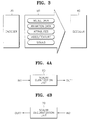
- FIG. 3 is a schematic diagram for explaining a 3D animation data format, and shows an encoder 30 , a decoder 40 , and a 3D animation file format 50 .
- the 3D animation file format 50 output from the encoder 30 to the decoder 40 is formed with model data, animation data, attributes, video/texture, and sound.
- an interpolator corresponds to animation data which efficiently expresses a 3D animation path.
- 3D animation data expressed by the VRML or MPEG-4 is formed with information shown in FIG. 3 . While standardized compression technologies are provided for audio, video, and 3D models, only expression-oriented general-purpose compression technologies are provided for interpolator for determining an animation path. In animation excluding audio/video, the amount of data for animation paths together with 3D models take most of the needed amount of data.
- MPEG-4 Binary Format for Scene provides a basic quantization/compression method for animation
- the method is not a technology dedicated for interpolators but a general-purpose compression technology and has poor compression performance. This is disclosed in Euee S. Jang “3D Animation Coding: its History and Framework”, proceedings of the International Conference on multimedia and Expo held in New York city in 2000.
- FIGS. 4 a and 4 b are block diagrams of prior art animation path compression and reconstruction apparatuses, respectively.
- the prior art compression apparatus of FIG. 4 a is formed with a scalar quantization unit 60
- the prior art reconstruction apparatus of FIG. 4 b is formed with a scalar dequantization unit 70 .
- An original animation path is input in the form of (key, key_value) through an input terminal IN 1 to the scalar quantization unit 60 of FIG. 4 a and is scalar quantized.
- An encoded bit stream which is the result of scalar quantization is output through an output terminal OUT 1 .
- the scalar dequantization unit 70 of FIG. 4 b receives the encoded bit stream through an input terminal IN 2 and outputs data in the form of a reconstructed animation path (key, key_value) through an output terminal OUT 2 .
- the interpolator compression in the prior art MPEG-4 BIFS needs scalar quantization as shown in FIG. 4 a .
- the prior art compression process of FIG. 4 a is applied not only to interpolators but to all elements that need compression in the BIFS.
- an animation path is reconstructed through the scalar dequantization unit 70 , using the encoded bit stream input to the prior art reconstruction apparatus of FIG. 4 b .
- keys and key values of interpolators are compressed in a uniform way, without considering the characteristics of each kind, so compression cannot be maximized.
- an apparatus for compressing an animation path having an interpolator analysis unit for extracting a predetermined number of break points from an animation path and outputting keys and key values corresponding to the break points; a key coder for coding keys output from the interpolator analysis unit; a key value coder for coding key values output from the interpolator analysis unit; and an entropy encoder for entropy encoding the keys and key values which are coded in the key coder and key value coder, respectively, and outputting encoded bit streams.
- an apparatus for reconstructing an animation path having an entropy decoder for receiving an encoded bit stream and entropy decoding the bit stream; a key decoder for receiving the entropy decoded result and decoding keys; a key value decoder for receiving the entropy decoded result and decoding key values; and an interpolator reconstruction unit for obtaining empty key values by linear interpolation based on the keys and key values decoded in the key decoder and the key value decoder, respectively, and reconstructing the original animation path.
- a method for compressing an animation path having the steps of extracting a predetermined number of break points from an original animation path; extracting keys and key values using the extracted break points, and coding the keys and key values; and entropy encoding the coded keys and key values to obtain encoded bit streams.
- a method for extracting break points of an animation path having the steps of (a) selecting two break points on both end points of the original animation path, among break points on the animation path; (b) selecting one break point among the remaining break points excluding the two selected break points; (c) interpolating for key values of the remaining break points excluding the selected break points, using the selected break points; (d) forming an approximated path based on the selected break points and the interpolated key values, selecting an approximated animation path which has the smallest path difference between the original animation path and the approximated animation path, and selecting break points corresponding to the selected animation path; and (e) selecting one break points among remaining break points excluding the break points selected in steps (a) and (b), and repeating steps (c) to (e) until the path difference is less than an allowable difference.
- the path difference is expressed by the sum of areas of trapezoids or twisted trapezoids which are formed by the original animation path and the approximated animation path.
- the path difference is defined as a differential rotation angle in a differential rotation transformation, which is the difference between a rotation transformation of the original animation path and a rotation transformation of the approximated path.
- a method for reconstructing an animation path having the steps of receiving and entropy decoding an encoded bit stream; decoding keys and key values from the result of entropy decoding; and reconstructing an original animation path by obtaining empty key values by linear interpolation based on the decoded keys and key values.
- a data format of a bit stream which is obtained by encoding an animation path, the data format having a key flag for indicating key values of which axes are selected among key values corresponding to an x, y, or z coordinate of each break point of the animation path; an array-type key for indicating that at least one or more key values are selected among key values corresponding to an x, y, or z coordinate of each break point; and array-type key values for indicating key values selected for each break point.
- FIG. 1 is a diagram for explaining an animation path in ordinary 3-Dimensional (3D) animation
- FIG. 2 is an example of an expression of an animation path used in the Virtual Reality Modeling Language (VRML) or MPEG-4;
- VRML Virtual Reality Modeling Language
- MPEG-4 MPEG-4
- FIG. 3 is a schematic diagram for explaining a data format of 3D animation
- FIGS. 4 a and 4 b are block diagrams of prior art animation path compression and reconstruction apparatuses, respectively;
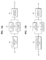
- FIGS. 5 a and 5 b are block diagrams of animation path compression and reconstruction apparatuses according to the present invention, respectively;
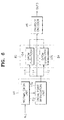
- FIG. 6 is a block diagram of a preferred embodiment of the compression apparatus according to the present invention of FIG. 5 a;
- FIG. 7 is a block diagram of a preferred embodiment of the reconstruction apparatus according to the present invention of FIG. 5 b;
- FIGS. 8 a through 8 h are diagrams for explaining a preferred embodiment of extracting break points using linear approximation according to the present invention.
- FIG. 9 is a diagram for explaining a method for obtaining the difference between a real animation path and an approximated animation path
- FIG. 10 is a diagram of a quantization process, and more particularly, of a Differential Pulse Code Modulation (DPCM) coding method which is generally used;
- DPCM Differential Pulse Code Modulation
- FIGS. 11 a through 11 e are diagrams for showing formats of coded bit streams according to the present invention.
- FIG. 12 is a table for explaining a decoding process expressed in a syntax expression according to the present invention.
- FIGS. 13 a through 13 d are graphs of experimental animation sequences for comparing the compression method of the present invention with the prior art compression method.
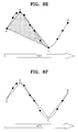
- FIGS. 14 a through 14 f are diagrams for explaining another preferred embodiment of extracting break points using spherical linear approximation according to the present invention.
- interpolator expressions used are those used in the VRML/MPEG-4, and the fields in which the interpolators are used include online computer games, animation advertisements, etc.
- FIG. 5 a is a block diagram of an apparatus for compressing an animation path according to the present invention, the apparatus including an interpolator analysis unit 80 , a Key (K) coder 82 , a Key Value (KV) coder 84 , and an entropy encoder 86 .
- FIG. 5 b is a block diagram of an apparatus for reconstructing an animation path according to the present invention, the apparatus including of an entropy decoder 90 , a key decoder 92 , a key value decoder 94 , and an interpolator reconstruction unit 96 .
- the interpolator analysis unit 80 of the compression apparatus of FIG. 5 a selects keys and key values to be encoded, and may be designed in consideration of the characteristics of different types of interpolators. An example of detailed analysis will be explained later.
- FIG. 6 is a block diagram of a preferred embodiment of the compression apparatus according to the present invention of FIG. 5 a .
- the compression apparatus of FIG. 6 includes the interpolator analysis unit 80 having a normalization unit 100 and a break point minimization unit 102 , the key coder 82 having a Differential Pulse Code Modulation (DPCM) quantizer 104 , the key value coder 84 having a DPCM quantization unit 106 , and the entropy encoder 86 .
- DPCM Differential Pulse Code Modulation
- FIG. 7 is a block diagram of a preferred embodiment of the reconstruction apparatus according to the present invention of FIG. 5 b .
- the reconstruction apparatus includes the entropy decoder 90 , the key decoder 92 having a DPCM dequantizer 126 , the key value decoder 94 having a DPCM dequantizer 128 , and the interpolator reconstruction unit having a key & key value reconstruction unit 95 .
- Interpolator expression provided to the input of the interpolator analysis unit 80 includes keys (K) and key values (KV).
- the interpolator analysis unit 80 adjusts the number of break points so that an animation path, which is input through an input terminal IN 3 , can be expressed by a minimum number of break points. If the original number of break points of the animation path is N, the number of break points output from the interpolator analysis unit 80 is adjusted to M (M ⁇ N). That is, the interpolator analysis unit 80 extracts break points from the original animation path input to the input terminal IN 3 .
- a key and key values can be respectively normalized and used.
- the normalization unit 100 normalizes each of the key and key values in the original animation path which is input through the input terminal IN 3 , and outputs normalized results to the break point minimization unit 102 .
- a key supported by the VRML has a value between 0 and 1 inclusive.
- the way the interpolator analysis unit 80 adjusts the number of break points may be determined so that the difference of the animation path generated by the adjusted break points and the original animation path is minimized.
- the break point minimization unit 102 makes break points extracted from the normalized key and key values, which are output from the normalization unit 102 , so that the number of the extracted break points is minimized.
- the break point minimization unit 102 determines break points so that the area representing error between the real path and the quantized path, which is determined by the interpolator analysis unit 80 , is minimized.
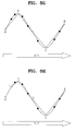
- FIGS. 8 a through 8 h are diagrams for explaining a preferred embodiment of extracting break points using linear approximation according to the present invention.
- Each dot on the animation paths represents a break point.
- FIG. 8 a is the original animation path.
- FIG. 8 b shows a process for finding both end points (A, B) of the path.
- FIG. 8 c shows a process for selecting a break point which is the closest to the original path.
- FIG. 8 d shows break points, A, B, and C, which are selected first.
- FIG. 8 e shows a process for extracting the second break points that are close to the original path.
- FIG. 8 f shows break points, A, B, C, and D, which are selected second.
- FIG. 8 g shows break points, A, B, C, D, and E, which are selected third.
- FIG. 8 h shows break points, A, B, C, D, E, and F, which are selected fourth.
- FIG. 9 is a diagram for explaining a method for obtaining the difference between a real animation path and an approximated animation path.
- the difference between the two paths is expressed by a trapezoid or a twisted trapezoid. Equation 1 for obtaining the area of the trapezoid, and equation 2 for obtaining the area of the twisted trapezoid are provided below.
- the difference between the real animation path 200 and the approximated animation path 210 can be expressed by the sum of the area of the trapezoids and the area of the twisted trapezoids. The sum of the areas is the area difference (D A ) between the two paths as shown in equation 3.
- D trapezoid ( a + b ) ⁇ h 2 ( 1 )
- D twisted_trapezoid 1 2 ⁇ ( a 2 + b 2 ) ( a + b ) ⁇ h ( 2 )
- D A ⁇ i ⁇ D trapezoid + ⁇ j ⁇ D twisted_trapezoid ( 3 )
- Break points are extracted so that the area difference (D A ) of equation 3 is minimized.
- the break point minimization unit 102 extracts break points.
- the interpolator analysis unit 80 By passing through the interpolator analysis unit 80 , essential break points of the animation path are extracted.
- the number of extracted break points (M) may be the same as the number of the original break points.
- key values represent a position in a 3D space having X, Y, and Z axes, and an animation path is represented by three curves on X, Y and Z axes.
- the interpolator analysis unit 80 may extract break points on each axis, and at this time, break points at each axis may be different from those of other axes.
- the following table 2 shows the result of extracting new break points in the interpolator analysis unit 80 from a real path having 8 break points (P 0 , P 1 , P 2 , P 3 , P 4 , P 5 , P 6 , and P 7 ).
- key_flag denotes a key flag
- kv x , kv y , and kv z denote key values on X, Y and Z axes, respectively.
- ‘O’ indicates that a key value corresponding to an x, y, or z coordinate of each break point is selected.
- key value kv x is selected for break point P 0 .
- ‘X’ indicates that a key value corresponding to an axis on each break point is not selected.
- the key flag indicates the key values whose axes are selected among key values of X, Y, Z axes on each break point. For example, ‘7’ indicates that all key values of all axes are selected, and ‘6’ indicates that all key values, excluding the key value of the X axis, kv x , are selected.
- break points P 1 , P 3 , and P 6 are regarded as unnecessary break points (marked by ‘ ⁇ ’ in the key_flag space) because none of the key values of X, Y. and Z axes are selected on the break points.
- P 0 and P 7 are break points at both ends of the path, and key values of all axes are selected.
- the key value of the X axis is not selected, but key values on other axes are selected. Therefore, the interpolator analysis unit 80 determines keys corresponding to 5 break points, instead of the original 8 break points, and determines key values of each axis corresponding to selected break points. In table 2, 5 keys and 11 key values are needed.
- the corresponding relation between a key and key values may be represented by a key flag (key_flag), which is additionally transmitted.
- key_flag a key flag
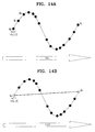
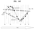
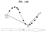
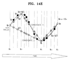
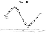
- FIGS. 14 a through 14 f are diagrams for explaining another preferred embodiment of extracting break points using spherical linear approximation according to the present invention. This shows a method for reducing break points (also referred to as key frames) in an orientation interpolator.
- FIG. 14 c shows a process for selecting a break point (the third break point) among the remaining break points excluding the two selected end break points.
- the number of methods for selecting one break point is (n ⁇ 1).
- spherical linear interpolation is performed for key values of break points which are not selected.
- a candidate animation path which has the least path difference is selected.
- a break point corresponding to the selected candidate animation path is selected among the (n ⁇ 1) candidate break points.
- FIG. 14 d shows that the path of candidate 2 of FIG. 1 is selected.
- the error between paths is obtained by using average error E m .
- the fourth break point is selected by performing the process explained referring to FIGS. 14 c and 14 d , after selecting a candidate break point among the remaining break points excluding the three selected break points of FIG. 14 d .
- FIG. 14 f shows that candidate 1 is selected.
- a quantization error is defined as a differential rotation angle in a differential rotation transformation, which is the difference between the rotation transformation of the original animation path and that of a reconstructed animation path. That is, assuming that ( ⁇ right arrow over (r) ⁇ , ⁇ ) denotes a key value of an orientation interpolator node and ( ⁇ right arrow over (r) ⁇ ′, ⁇ ′) denotes a key value reconstructed in the reconstruction unit 96 (vector ⁇ right arrow over (r) ⁇ denotes a rotation axis, ⁇ denotes a rotation amount, and the rotation amount satisfies ⁇ ⁇ [ ⁇ , ⁇ ]), when rotation transformation from an arbitrary position ⁇ right arrow over (x) ⁇ to ⁇ right arrow over (y) ⁇ and ⁇ right arrow over (y) ⁇ ′ in a 3D space by ( ⁇ right arrow over (r) ⁇ , ⁇ ) and ( ⁇ right arrow over (r) ⁇ ′, ⁇ ′) is performed, a quantization error occurring is calculated
- ⁇ right arrow over (e) ⁇ ( ⁇ right arrow over (x) ⁇ ) represents a quantization error vector
- ⁇ right arrow over (e) ⁇ ( ⁇ right arrow over (x) ⁇ ) ⁇ right arrow over (y) ⁇ right arrow over (y) ⁇ ′.
- ⁇ ′′ denotes a differential rotation angle between ⁇ right arrow over (y) ⁇ and ⁇ right arrow over (y) ⁇ ′
- Equation 8 indicates an instantaneous quantization error occuring at a predetermined time among all animation break points.
- an instantaneous quantization error at a predetermined time t can be expressed as the following equation 9: e ( t ) 2arccos( Q ( t ) ⁇ Q′ ( t )) (9)
- E′ m is first obtained for interval [t i ⁇ 1 , t i ] in order to obtain E m , using the following equation 11:
- E m ′ ⁇ 1 3 ⁇ ( t i - t i - 1 ) ⁇ ( ⁇ 2 ⁇ ( 0 ) + ⁇ 2 ⁇ ( 1 ) + ⁇ ⁇ ( 0 ) ⁇ ⁇ ⁇ ( 1 ) ) ( 16 )
- Equation 17 E m ′ ⁇ 4 3 ⁇ ( t i - t i - 1 ) ⁇ ( arccos 2 ⁇ ( Q ⁇ ( t i - 1 ) ⁇ Q ′ ⁇ ( t i - 1 ) ) + arccos 2 ⁇ ( Q ⁇ ( t i ) ⁇ Q ′ ⁇ ( t i ) ) + arccos ⁇ ( Q ⁇ ( t i - 1 ) ⁇ Q ′ ⁇ ( t i - 1 ) ) ⁇ arccos ⁇ ( Q ⁇ ( t i ) ⁇ Q ′ ⁇ ( t i ) ) ) ( 17 )
- a maximum value is selected from among the values of the maximum error E p l in each interval [t i ⁇ 1 , t i ], which is obtained by the following equation 19: E p l ⁇ max
- max2
- the interpolator analysis unit 80 shown in FIG. 6 sends information 114 on the number of keys, the minimum value and maximum value of normalized key values, the resolutions of key and key value , and a key flag, to the entropy encoder 86 .
- the interpolator analysis unit 80 sends keys 110 to the key coder 82 , and sends information on key values, including the minimum value and maximum value of normalized key values to the key value coder 84 .
- Coding keys and key values in the key coder 82 and key value coder 84 will now be explained.
- Keys and key values are DPCM quantization method compressed in the key coder 82 and the key value coder 84 , respectively.
- Quantized information together with other information is sent to the entropy encoder 86 , and output as a bit stream finally compression encoded through the output terminal OUT 3 .
- the DPCM quantizer 104 of the key coder 82 DPCM quantization codes (that is, codes the difference between the current value and the immediatley previous value) a key sent from the interpolator analysis unit 80 , and outputs the coded result to the entropy encoder 86 .
- the DPCM quantizer 106 of the key value coder 84 DPCM quantization codes (that is, codes the difference between the current value and the immediatley previous value) key values, and the minimum value and maximum value of the key values, which are sent by the interpolator analysis unit 80 , and outputs the coded result to the entropy encoder 86 .
- FIG. 10 is a diagram of a quantization process and shows the DPCM method which is generally used.
- a final error (e) is quantization compressed as the following equation 22.
- FIG. 10 explains equation 22. That is, the difference (d 1 ) between an immediately previous value (K i ⁇ 1 ) and the previous value (K i ⁇ 2 ) thereof is obtained. The difference value (d 1 ) is added to the immediately previous value (K i ⁇ 1 ) to generate an approximated value ( ⁇ circumflex over (K) ⁇ i ). Then, the final error (e) is obtained as the difference between the approximated value ( ⁇ circumflex over (K) ⁇ i ) and the current value (K i ).
- the error (e) may be simply obtained as the difference between the current value (K i ) and the immediately previous value (K i ⁇ 1 ).
- FIGS. 11 a through 11 e are diagrams for showing formats of coded bit streams according to the present invention.
- FIG. 11 a shows the format of a coded bit stream according to the present invention, which includes the number of keys (n_key), the resolution of keys (k_res), the resolution of key values (kv_res), the minimum value and maximum value of key values array ([min/max]) 230 , a key flag array ([key_flag]) 232 , a key array ([key]) 234 , and a key values array ([kv]) 236 .
- [ ] denotes an array.
- FIG. 11 b shows the format of the minimum value and maximum value of key values array 230 of FIG. 11 a
- FIG. 11 c shows the format of the key flag array 232
- FIG. 11 d shows the format of the key array 234
- FIG. 11 e shows the format of key values array 236 .
- the minimum value and maximum value of key values array 230 of FIG. 11 a are formed of the minimum values of X, Y. and Z axes (min x , min y , and min z ) and the maximum values of X, Y, and Z axes (max x , max y , max z ), as shown in FIG. 11 b .
- the key flag array 232 is formed of n key flags (key_flag 0 , key_flag 1 , key_flag 2 , key_flag 3 , . . . , key_flag n ⁇ 1 ).
- n denotes the number of keys.
- the key array 234 is formed of n keys (key 0 , key 1 , key 2 , . . . , key n ⁇ 1 ).
- data of keys and key flags for breakpoints which are classified as unnecessary ones, for example, breakpoints P 1 , P 3 and P 6 of Table 2 may be excluded from the key array or the key flag array.
- the key array and/or the key flag array may consist of data less than the number (n) of the original keys.
- the key values array 236 is formed of p first key values (kv_X 0 , kv_X 1 , . . .
- the apparatus and method for reconstructing an animation path according to the present invention is performed as the inverse of the compression process.
- the entropy decoder 90 of FIG. 7 receives an encoded bit stream through the input terminal IN 4 , entropy decodes the bit stream, and outputs the entropy decoded result to both the key decoder 92 and the key value decoder 94 .
- the key decoder 92 and the key value decoder 94 receive quantized keys and key values, respectively, which are the result of entropy decoding, and, using additional information such as the key flag, reconstruct the data before quantization.
- the key decoder 92 receives the entropy decoded result, and decodes the keys
- the key value decoder 94 receives the entropy decoded result, and decodes the key values.
- the key decoder 92 may be implemented as the DPCM dequantizer 126
- the key value decoder 94 may be implemented as the DPCM dequantizer 128 .
- Each DPCM dequantizer 126 or 128 decodes the input data which is decoded in the entropy decoder 90 by DPCM dequantization method.
- the interpolator reconstruction unit 96 receives the data decoded in the key decoder 92 and the key value decoder 94 , and reconstructs the original animation path.
- the interpolator reconstruction unit 96 receives information 124 on the number of keys, the minimum value and maximum value of normalized key values, the resolutions of keys and key values, and key flags, from the entropy decoder 90 , keys 120 from the key decoder 92 , and information 122 on key values and the minimum value and maximum value of normalized key values from the key value decoder 94 .
- the interpolator reconstruction unit 94 reconstructs empty key values by linear interpolation, using input information.
- the key value of the X axis on break point P 2 can be reconstructed by linear interpolation, using key values of P 0 and P 4 .
- the interpolator reconstruction unit 96 may be implemented as a key & key value reconstruction unit 95 .
- the reconstructed animation path in the form of (key, key values) is output through the output terminal OUT 4 .
- FIG. 12 is a table for explaining a decoding process expressed in a program language according to the present invention.
- the table is also referred to as a bit stream syntax.
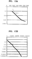
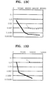
- FIGS. 13 a through 13 d are graphs of experimental animation sequences for comparing the compression method of the present invention with the prior art compression method.
- the vertical axis represents distortion degrees
- the horizontal axis represents the number of bits
- the method for compressing an animation path according to the present invention is marked by thick lines
- the prior art compression method is marked by dotted lines.
- FIGS. 13 a through 13 d show the results of simulations, in each of which a different animation path is applied.
- the method of the present invention shows increasingly better results in order of FIGS. 13 b – 13 a – 13 d – 13 c .
- the compression method of the present invention showed much better picture quality than the prior art BIFS method, while at the same picture quality, the compression method of the present invention showed much better compression rate.
- an interpolator expression of an animation path is used for simplification of the path using break points.
- the interval between each key is uniformly formed in the expression of the path, and therefore, break points are oversampled.
- break points are oversampled.
- the present invention by analyzing break points, a simplified encoded bit stream having a minimum number of break points is obtained.
- the DPCM compression maintains higher linear correlation between break points, and therefore efficient compression using the higher correlation is enabled.
Landscapes
- Engineering & Computer Science (AREA)
- Multimedia (AREA)
- Signal Processing (AREA)
- Physics & Mathematics (AREA)
- General Physics & Mathematics (AREA)
- Theoretical Computer Science (AREA)
- Processing Or Creating Images (AREA)
- Compression Or Coding Systems Of Tv Signals (AREA)
- Compression, Expansion, Code Conversion, And Decoders (AREA)
Abstract
Description
| TABLE 1 | ||
| Kinds | Characteristics | Functions |
| Scalar Interpolator | Linear interpolation of | Expression of width, |
| scalar change amount | radius, solidity, etc. | |
| Position Interpolator | Liner interpolation on 3D | Parallel movement |
| coordinates | in a 3D space | |
| Orientation Interpolator | Spherical Linear | Rotation in a 3D |
| interpolation of 3D axes | space | |
| and rotation amount | ||
| Coordinate Interpolator | Liner interpolation of 3D | 3D morphing |
| model coordinate change | ||
| amount | ||
| Normal Interpolator | Spherical Linear | Expression of 3D |
| interpolation of 3D | normal vector | |
| normal coordinates | change | |
| Color Interpolator | Linear interpolation of | Expression of color |
| color tone information | tone change amount | |
| TABLE 2 | ||||||||
| Break Points | P0 | P1 | P2 | P3 | P4 | P5 | P6 | P7 |
| kvx | ◯ | X | X | X | ◯ | X | X | ◯ |
| kvy | ◯ | X | ◯ | X | ◯ | X | X | ◯ |
| kvz | ◯ | X | ◯ | X | X | ◯ | X | ◯ |
| key | ◯ | X | ◯ | X | ◯ | ◯ | X | ◯ |
| key_flag | 7 | — | 6 | — | 3 | 4 | — | 7 |
Y=Q*X*Q*
X=Q**Y*Q (5)
Y′=Q′*X*Q′*=Q′*Q**Y*Q*Q′*=Q″*Y*Q″* (6)
Q″=Q′*Q* (7)
θ″=2 cos−1 q 0″=2 cos−1(Q′·Q), θ″ε[0,π], q 0 ″=Q′·Q, (8)
-
- (· indicates inner product operation)
e(t) 2arccos(Q(t)·Q′(t)) (9)
4arccos2(Q(t)·Q′(t))=φ2(α), t=t l−1+α(t l −t l−1) (12)
φ(α)≅φ(0)+α(φ(1)−φ(0))
φ2(α)≅φ2(0)+α2(φ(1)−φ(0))2+2αφ(0)(φ(1)−φ(0)) (14)
E p l≅max|e(t)|=max2|arccos(Q(t)·Q′(t))| (19)
E p l≅max(φ(0),φ(1))=max{2|arccos(Q(t l−1)·Q′(t l−1))|,2|arccos(Q(t l)·Q′(tl))|} (20)
E p≅maxE l p, for i=1,2, . . . , L (21)
K i=0, for i<0
{circumflex over (K)} i =K i−1 +
e=d 2 (22)
Claims (21)
Applications Claiming Priority (4)
| Application Number | Priority Date | Filing Date | Title |
|---|---|---|---|
| KR20000070090 | 2000-11-23 | ||
| KR2000-70090 | 2000-11-23 | ||
| KR2001-40704 | 2001-07-07 | ||
| KR1020010040704A KR100561835B1 (en) | 2000-11-23 | 2001-07-07 | Method and apparatus for compression and restoration of animation path using linear approximation |
Publications (2)
| Publication Number | Publication Date |
|---|---|
| US20020097246A1 US20020097246A1 (en) | 2002-07-25 |
| US7006097B2 true US7006097B2 (en) | 2006-02-28 |
Family
ID=36648539
Family Applications (1)
| Application Number | Title | Priority Date | Filing Date |
|---|---|---|---|
| US09/988,708 Expired - Fee Related US7006097B2 (en) | 2000-11-23 | 2001-11-20 | Method and apparatus for compression and reconstruction of animation path using linear approximation |
Country Status (8)
| Country | Link |
|---|---|
| US (1) | US7006097B2 (en) |
| EP (1) | EP1209626B1 (en) |
| JP (1) | JP3694477B2 (en) |
| CN (1) | CN1215440C (en) |
| CA (1) | CA2363385C (en) |
| DE (1) | DE60126895T2 (en) |
| ES (1) | ES2282209T3 (en) |
| RU (1) | RU2236751C2 (en) |
Cited By (4)
| Publication number | Priority date | Publication date | Assignee | Title |
|---|---|---|---|---|
| US20060250402A1 (en) * | 2005-02-28 | 2006-11-09 | Kenneth Perlin | Method and apparatus for creating a computer simulation of an actor |
| US20060274951A1 (en) * | 2003-02-27 | 2006-12-07 | T-Mobile Deutschland Gmbh | Method for the compressed transmission of image data for three-dimensional representation of scenes and objects |
| US10381808B2 (en) | 2016-09-26 | 2019-08-13 | Norman R. Byrne | Cord system for height-adjustable furniture |
| US11408572B2 (en) | 2014-03-15 | 2022-08-09 | Ideal Industries Lighting Llc | Luminaires utilizing optical waveguide |
Families Citing this family (7)
| Publication number | Priority date | Publication date | Assignee | Title |
|---|---|---|---|---|
| DE60239586D1 (en) | 2001-11-27 | 2011-05-12 | Samsung Electronics Co Ltd | Key value coding and decoding of orientation interpolator nodes |
| US7809204B2 (en) * | 2002-10-18 | 2010-10-05 | Samsung Electronics Co., Ltd. | Method and apparatus for encoding and decoding key value data of coordinate interpolator |
| US20050168485A1 (en) * | 2004-01-29 | 2005-08-04 | Nattress Thomas G. | System for combining a sequence of images with computer-generated 3D graphics |
| US7653528B2 (en) * | 2005-03-08 | 2010-01-26 | Microsoft Corporation | Resource authoring incorporating ontology |
| US20060274070A1 (en) * | 2005-04-19 | 2006-12-07 | Herman Daniel L | Techniques and workflows for computer graphics animation system |
| US7477254B2 (en) * | 2005-07-13 | 2009-01-13 | Microsoft Corporation | Smooth transitions between animations |
| CN111343462B (en) * | 2020-03-08 | 2021-10-22 | 苏州浪潮智能科技有限公司 | A kind of image data compression transmission method, device and storage medium |
Citations (12)
| Publication number | Priority date | Publication date | Assignee | Title |
|---|---|---|---|---|
| WO1987004032A1 (en) | 1985-12-24 | 1987-07-02 | British Broadcasting Corporation | Method of transmitting a video signal in sampled form |
| JPH06162159A (en) | 1992-06-12 | 1994-06-10 | Nippon Steel Corp | Method and apparatus for processing graphic data |
| GB2296839A (en) | 1994-12-29 | 1996-07-10 | Hyundai Electronics Ind | Shape information reduction apparatus |
| JPH08212386A (en) | 1995-02-03 | 1996-08-20 | Fujitsu Ltd | Animation path creation device |
| EP0789327A2 (en) | 1996-02-09 | 1997-08-13 | Matsushita Electric Industrial Co., Ltd. | Contour coding method |
| CN1170909A (en) | 1996-04-25 | 1998-01-21 | 松下电器产业株式会社 | Transmitter-receiver of three-dimensional skeleton and transmitting-receiving method for action |
| EP0851684A2 (en) | 1996-12-23 | 1998-07-01 | Daewoo Electronics Co., Ltd | Method and apparatus for encoding a contour of an object |
| CN1197250A (en) | 1997-04-24 | 1998-10-28 | 三菱电机株式会社 | Animation image coding method, animation image encoding device, and decoding device |
| WO1999064944A2 (en) | 1998-06-08 | 1999-12-16 | Microsoft Corporation | Compression of time-dependent geometry |
| JP2000149039A (en) | 1998-07-17 | 2000-05-30 | Matsushita Electric Ind Co Ltd | Transmitting device, transmitting method, receiving device, receiving method, and communication system using multidimensional stream data |
| US20020036639A1 (en) * | 2000-01-31 | 2002-03-28 | Mikael Bourges-Sevenier | Textual format for animation in multimedia systems |
| US6559848B2 (en) * | 2000-12-13 | 2003-05-06 | Intel Corporation | Coding and decoding three-dimensional data |
Family Cites Families (4)
| Publication number | Priority date | Publication date | Assignee | Title |
|---|---|---|---|---|
| FR2697360B1 (en) * | 1992-10-26 | 1994-12-30 | Jeux Franc | Acquisition and playback system of a sequence of animated video images in real time. |
| KR100363588B1 (en) * | 1993-03-25 | 2003-02-17 | 세이코 엡슨 가부시키가이샤 | Image processing device |
| US6034697A (en) * | 1997-01-13 | 2000-03-07 | Silicon Graphics, Inc. | Interpolation between relational tables for purposes of animating a data visualization |
| US6028608A (en) * | 1997-05-09 | 2000-02-22 | Jenkins; Barry | System and method of perception-based image generation and encoding |
-
2001
- 2001-11-20 US US09/988,708 patent/US7006097B2/en not_active Expired - Fee Related
- 2001-11-21 CA CA 2363385 patent/CA2363385C/en not_active Expired - Fee Related
- 2001-11-22 ES ES01309832T patent/ES2282209T3/en not_active Expired - Lifetime
- 2001-11-22 RU RU2001131591A patent/RU2236751C2/en not_active IP Right Cessation
- 2001-11-22 DE DE2001626895 patent/DE60126895T2/en not_active Expired - Lifetime
- 2001-11-22 EP EP20010309832 patent/EP1209626B1/en not_active Expired - Lifetime
- 2001-11-22 JP JP2001357514A patent/JP3694477B2/en not_active Expired - Fee Related
- 2001-11-23 CN CNB011394234A patent/CN1215440C/en not_active Expired - Fee Related
Patent Citations (12)
| Publication number | Priority date | Publication date | Assignee | Title |
|---|---|---|---|---|
| WO1987004032A1 (en) | 1985-12-24 | 1987-07-02 | British Broadcasting Corporation | Method of transmitting a video signal in sampled form |
| JPH06162159A (en) | 1992-06-12 | 1994-06-10 | Nippon Steel Corp | Method and apparatus for processing graphic data |
| GB2296839A (en) | 1994-12-29 | 1996-07-10 | Hyundai Electronics Ind | Shape information reduction apparatus |
| JPH08212386A (en) | 1995-02-03 | 1996-08-20 | Fujitsu Ltd | Animation path creation device |
| EP0789327A2 (en) | 1996-02-09 | 1997-08-13 | Matsushita Electric Industrial Co., Ltd. | Contour coding method |
| CN1170909A (en) | 1996-04-25 | 1998-01-21 | 松下电器产业株式会社 | Transmitter-receiver of three-dimensional skeleton and transmitting-receiving method for action |
| EP0851684A2 (en) | 1996-12-23 | 1998-07-01 | Daewoo Electronics Co., Ltd | Method and apparatus for encoding a contour of an object |
| CN1197250A (en) | 1997-04-24 | 1998-10-28 | 三菱电机株式会社 | Animation image coding method, animation image encoding device, and decoding device |
| WO1999064944A2 (en) | 1998-06-08 | 1999-12-16 | Microsoft Corporation | Compression of time-dependent geometry |
| JP2000149039A (en) | 1998-07-17 | 2000-05-30 | Matsushita Electric Ind Co Ltd | Transmitting device, transmitting method, receiving device, receiving method, and communication system using multidimensional stream data |
| US20020036639A1 (en) * | 2000-01-31 | 2002-03-28 | Mikael Bourges-Sevenier | Textual format for animation in multimedia systems |
| US6559848B2 (en) * | 2000-12-13 | 2003-05-06 | Intel Corporation | Coding and decoding three-dimensional data |
Non-Patent Citations (3)
| Title |
|---|
| A. K. Jain, "Fundamentals of digital Image Process", Chapter 9, pp. 342-431, published by Prentice Hall Englewood Cliffs, NJ, in 1989. |
| Bourges-Sevenier, M. et al., Animation framework for MPEG-4 systems, 2000 IEEE International Conference on New York, NY, Jul. 2000, pp. 1115-1118. |
| Euee S. Jang, "3D Animation Coding: its History and Framework", Proceedings of the International Conference of Multimedia and Expo held in New York city in 2000. |
Cited By (6)
| Publication number | Priority date | Publication date | Assignee | Title |
|---|---|---|---|---|
| US20060274951A1 (en) * | 2003-02-27 | 2006-12-07 | T-Mobile Deutschland Gmbh | Method for the compressed transmission of image data for three-dimensional representation of scenes and objects |
| US7212662B2 (en) * | 2003-02-27 | 2007-05-01 | T-Mobile Deutschland Gmbh | Method for the compressed transmission of image data for 3-dimensional representation of scenes and objects |
| US20060250402A1 (en) * | 2005-02-28 | 2006-11-09 | Kenneth Perlin | Method and apparatus for creating a computer simulation of an actor |
| US8243078B2 (en) * | 2005-02-28 | 2012-08-14 | Kenneth Perlin | Method and apparatus for creating a computer simulation of an actor |
| US11408572B2 (en) | 2014-03-15 | 2022-08-09 | Ideal Industries Lighting Llc | Luminaires utilizing optical waveguide |
| US10381808B2 (en) | 2016-09-26 | 2019-08-13 | Norman R. Byrne | Cord system for height-adjustable furniture |
Also Published As
| Publication number | Publication date |
|---|---|
| EP1209626B1 (en) | 2007-02-28 |
| CN1215440C (en) | 2005-08-17 |
| EP1209626A2 (en) | 2002-05-29 |
| CN1356669A (en) | 2002-07-03 |
| DE60126895T2 (en) | 2007-11-08 |
| ES2282209T3 (en) | 2007-10-16 |
| US20020097246A1 (en) | 2002-07-25 |
| CA2363385A1 (en) | 2002-05-23 |
| RU2236751C2 (en) | 2004-09-20 |
| JP2002230581A (en) | 2002-08-16 |
| EP1209626A3 (en) | 2003-11-12 |
| DE60126895D1 (en) | 2007-04-12 |
| CA2363385C (en) | 2006-07-04 |
| JP3694477B2 (en) | 2005-09-14 |
Similar Documents
| Publication | Publication Date | Title |
|---|---|---|
| US7206457B2 (en) | Method and apparatus for encoding and decoding key value data of coordinate interpolator | |
| JP4166679B2 (en) | Method and apparatus for encoding and decoding three-dimensional object data | |
| JP3023961B2 (en) | Encoder and decoder | |
| EP1199894B1 (en) | Coding apparatus and method for orientation interpolator node | |
| KR100513732B1 (en) | Method and apparatus for encoding and decoding 3 dimensional data | |
| EP1239680B1 (en) | Encoding method and apparatus of deformation information of 3D object | |
| KR20030043657A (en) | Encoding/decoding method and apparatus for position interpolator | |
| US7006097B2 (en) | Method and apparatus for compression and reconstruction of animation path using linear approximation | |
| Jang et al. | Interpolator data compression for MPEG-4 animation | |
| US7809204B2 (en) | Method and apparatus for encoding and decoding key value data of coordinate interpolator | |
| JP2007116725A (en) | Predictive coding method and system for data array | |
| CN100546386C (en) | Method and apparatus for encoding and decoding key value data of a coordinate interpolator | |
| US6529086B2 (en) | Encoding/decoding apparatus for orientation interpolator node data | |
| KR100561835B1 (en) | Method and apparatus for compression and restoration of animation path using linear approximation | |
| KR100590522B1 (en) | Coding apparatus and method for orientation interpolator node | |
| EP1322120B1 (en) | Encoding and decoding key value data of orientation interpolator node | |
| EP1592253B1 (en) | Generating differentially coded data of quantized coordinate data of vertices of moving objects |
Legal Events
| Date | Code | Title | Description |
|---|---|---|---|
| AS | Assignment |
Owner name: SAMSUNG ELECTRONICS CO., LTD., KOREA, REPUBLIC OF Free format text: ASSIGNMENT OF ASSIGNORS INTEREST;ASSIGNORS:JANG, EUEE-SEON;KIM, DO-KYOON;WOO, SANG-OAK;REEL/FRAME:012315/0837 Effective date: 20011116 |
|
| FEPP | Fee payment procedure |
Free format text: PAYOR NUMBER ASSIGNED (ORIGINAL EVENT CODE: ASPN); ENTITY STATUS OF PATENT OWNER: LARGE ENTITY |
|
| FPAY | Fee payment |
Year of fee payment: 4 |
|
| FEPP | Fee payment procedure |
Free format text: PAYOR NUMBER ASSIGNED (ORIGINAL EVENT CODE: ASPN); ENTITY STATUS OF PATENT OWNER: LARGE ENTITY Free format text: PAYER NUMBER DE-ASSIGNED (ORIGINAL EVENT CODE: RMPN); ENTITY STATUS OF PATENT OWNER: LARGE ENTITY |
|
| FPAY | Fee payment |
Year of fee payment: 8 |
|
| FEPP | Fee payment procedure |
Free format text: MAINTENANCE FEE REMINDER MAILED (ORIGINAL EVENT CODE: REM.) |
|
| LAPS | Lapse for failure to pay maintenance fees |
Free format text: PATENT EXPIRED FOR FAILURE TO PAY MAINTENANCE FEES (ORIGINAL EVENT CODE: EXP.) |
|
| STCH | Information on status: patent discontinuation |
Free format text: PATENT EXPIRED DUE TO NONPAYMENT OF MAINTENANCE FEES UNDER 37 CFR 1.362 |
|
| FP | Lapsed due to failure to pay maintenance fee |
Effective date: 20180228 |