JP3691908B2 - Storage device - Google Patents
Storage device Download PDFInfo
- Publication number
- JP3691908B2 JP3691908B2 JP16647596A JP16647596A JP3691908B2 JP 3691908 B2 JP3691908 B2 JP 3691908B2 JP 16647596 A JP16647596 A JP 16647596A JP 16647596 A JP16647596 A JP 16647596A JP 3691908 B2 JP3691908 B2 JP 3691908B2
- Authority
- JP
- Japan
- Prior art keywords
- storage device
- recording disk
- motor
- information recording
- assembly
- Prior art date
- Legal status (The legal status is an assumption and is not a legal conclusion. Google has not performed a legal analysis and makes no representation as to the accuracy of the status listed.)
- Expired - Fee Related
Links
- 230000001360 synchronised effect Effects 0.000 claims description 17
- 210000000078 claw Anatomy 0.000 claims description 12
- 230000002093 peripheral effect Effects 0.000 claims description 9
- 239000002861 polymer material Substances 0.000 claims description 4
- 229910000831 Steel Inorganic materials 0.000 claims description 3
- 239000010959 steel Substances 0.000 claims description 3
- 238000005452 bending Methods 0.000 claims description 2
- 238000000034 method Methods 0.000 description 5
- 230000004907 flux Effects 0.000 description 4
- 230000005284 excitation Effects 0.000 description 3
- RYGMFSIKBFXOCR-UHFFFAOYSA-N Copper Chemical compound [Cu] RYGMFSIKBFXOCR-UHFFFAOYSA-N 0.000 description 1
- 229910000976 Electrical steel Inorganic materials 0.000 description 1
- 230000007423 decrease Effects 0.000 description 1
- 230000000694 effects Effects 0.000 description 1
- 230000005484 gravity Effects 0.000 description 1
- 239000000696 magnetic material Substances 0.000 description 1
- 230000005415 magnetization Effects 0.000 description 1
- 238000000465 moulding Methods 0.000 description 1
- 229920003023 plastic Polymers 0.000 description 1
- 239000004033 plastic Substances 0.000 description 1
- 229920002635 polyurethane Polymers 0.000 description 1
- 239000004814 polyurethane Substances 0.000 description 1
- 238000010248 power generation Methods 0.000 description 1
- 239000007787 solid Substances 0.000 description 1
- 238000004804 winding Methods 0.000 description 1
Images

Classifications
-
- G—PHYSICS
- G11—INFORMATION STORAGE
- G11B—INFORMATION STORAGE BASED ON RELATIVE MOVEMENT BETWEEN RECORD CARRIER AND TRANSDUCER
- G11B17/00—Guiding record carriers not specifically of filamentary or web form, or of supports therefor
- G11B17/02—Details
- G11B17/022—Positioning or locking of single discs
Landscapes
- Rotational Drive Of Disk (AREA)
- Permanent Magnet Type Synchronous Machine (AREA)
Description
【0001】
【発明の属する技術分野】
本発明は、FDD、HDD、CD−ROM等に代表される記憶装置に関する。
【0002】
【従来の技術】
この種の記憶装置は、装置の構成部品を取り付けたり収容するシャーシと、情報記録用の円盤を回転駆動するスピンドルモータと、情報記録用円盤に情報の読み書きを行う磁気ヘッドと、この磁気ヘッドを情報記録用円盤の半径方向に駆動するアクチュエータと、装置全体の動作を制御する制御回路とから構成されている。これらの構成部品の中でコストが最も高く、高精度が要求されるスピンドルモータには、その要求性能の高さから従来は3相ブラシレスDCモータが使用されてきた。
【0003】
【発明が解決しようとする課題】
しかし、近年の価格低下に対する対応は限界に達し、さらに安く構成できるモータが求められているが、クローポール型2相同期モータに着目すると、同モータは基本的にはステッピングモータであるために、その軸速度は速度変動が大きくしかも励磁状態により回転軸が上下動するために、スピンドルモータとして求められる滑らかな回転が得られず、満足できる状態で採用することはなかなか出来ないでいた。また、モータの構成上からモータ駆動用励磁コイルがソレノイドコイルとなるので、励磁のたびに大きな漏洩磁束が発生し、これが磁気ヘッドに鎖交してヘッド出力信号のS/Nを悪化させるという問題があった。
【0004】
本発明は、上記の点にかんがみてなされたもので、クローポール型2相同期モータの問題点である軸の回転ムラと上下動を抑えるとともに、漏洩磁束を抑えて、安価なクローポール型2相同期モータをスピンドルモータとして採用すると同時に、モータの制御方式をオープンループ方式とし、装置を制御する制御回路側に駆動回路を設け、さらには制御用LSIに駆動回路を組み込み、モータの制御の駆動回路(駆動IC)を廃止して、大幅にコストを削減した記憶装置を提供するものである。
【0005】
本発明は上記の目的を達成するために、フレームと、情報記録用円盤と、該情報記録用円盤に読み書きを行うヘッドと、該ヘッドを駆動するアクチュエータと、前記情報記録用円盤を回転駆動するスピンドルモータを備え、前記スピンドルモータが、軟磁性鋼板を折り曲げて極歯を構成した2枚のステータヨークの間にアーマチュアコイルを挟み込んだものをモータの軸方向に複数個重ねてステータ組立体を形成し、該ステータ組立体の極歯と微小間隔隔てて対向するように設けられた永久磁石より成る界磁用ロータを有するクローポール型同期モータから成る記憶装置において、前記クローポール型同期モータは、前記ステータ組立体と、シャフトと界磁用ロータから成るロータ組立体と、前記シャフトを軸支して成る軸受と、ベースと、から成る構成であって、前記ステータ組立体と前記軸受を同軸に前記ベース上に配設し、前記ベースと前記ステータ組立体と前記軸受とを高分子材料にて一体化して、前記ベースを前記フレームに固定して成るようにした。
【0006】
また前記クローポール型同期モータの基本ステップ数は滑らかな回転を得るために48ステップ以上とするのが好ましい。
【0007】
また前記情報記録用円盤を載置する前記ロータ組立体の面に前記情報記録用円盤を吸着保持するための着磁が施されて成るようにした。
【0008】
また前記ステータ組立体の上面に磁気シールド板を配設し、磁気シールド板には剛性向上を図るため外周縁と内周縁に起こし部を設けた。
【0009】
さらにクローポール型同期モータの駆動制御をオープンループ方式とした。
【0010】
【発明の実施の形態】
以下、本発明の実施の形態を図面により説明する。
【0011】
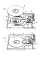
図1は本発明による記憶装置の一例としてのFDDの内部構成を示す斜視図であり、(a)は情報記録用円盤である磁気記録円盤を上方に取り外した状態、(b)は磁気記録円盤を装着した状態を示す。
【0012】
図において、1はフレ−ム、2は読み書き用磁気ヘッド、3は磁気ヘッド2を磁気記録円盤5の径方向に駆動するアクチュエ−タ、4は磁気記録円盤5を回転駆動するスピンドルモ−タ、5は情報を磁気記録する磁気記録円盤(フロッピ−ディスク)、6はフレ−ム1の裏面に実装されていてFDD装置の入出力用コネクタ−を備えた制御回路を示す。フレ−ム1にはスピンドルモ−タ4、磁気ヘッド2、アクチュエ−タ3が取り付けられており、スピンドルモ−タ4の上には磁気記録円盤5が載せられて、この円盤5の両面を磁気ヘッド2で挟んで情報の記録または再生を行う。このとき磁気ヘッド2はアクチュエ−タ3により駆動されて、磁気記録円盤5の最内周側の79トラックから最外周側の0トラックまでを円盤5の半径方向にスキャンする。
【0013】
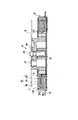
図2は図1に示したスピンドルモ−タ4の構成を示す縦断面図であり、11はシ−ルド板、12はステ−タ組立体、13はベ−ス、14はロ−タ組立体、15はシャフト、16は軸受、17はドライブピン、18はステ−タヨ−クA、19はステ−タヨ−クB、20はコイル、21はコイルの引出し端子を示す。
【0014】
詳細に説明すると、ベ−ス13上には、軟磁性鋼板を折り曲げて内周面に12個以上の極歯を形成したステ−タヨ−クA18と、このステータヨーク18と同じ構成のステ−タヨ−クB19とを互いの極歯が電気角で180°ずれるように向い合わせ、その間にポリウレタン被覆銅線を卷回して形成したアーマチュアコイル20を挟持してサブ組立体30を構成し、このような構成のサブ組立体30を2個、極歯が電気角で90°±5°となるようにモータの軸方向に背中合わせに重ね、ステ−タ組立体12が構成されている。ステ−タ組立体12には、回転中心となるシャフト15を支える軸受16とステ−タ組立体12の極歯との同心を出して配置し、ベ−ス13、ステ−タ組立体12、軸受16の3つを高分子材料でモ−ルドにより一体化する。ここでステ−タヨ−クA、Bの極歯の数を12個以上としたのは、12個以下だと1回転あたり48ステップ以下のモ−タとなり、軸の回転速度ムラが4.0%以上と大きくなってスピンドルモ−タとして使用できないからである。またステ−タの極歯の位置を規定するのは、前記規定範囲内(90°±5°)でないと滑らかな回転が得られなく、回転ムラが4.0%以上となるからである。
【0015】
次に中心にシャフト15を配し、適切なイナーシャとなるように比重の大きな磁性材料入り高分子材料(プラスチックマグネット)で構成したロ−タ組立体14の外周面に界磁用着磁を施すとともに、磁気記録円盤5と対向する面に磁気記録円盤5を吸着保持するための着磁を施し、さらに、反対の端面にはロ−タ組立体14の軸方向の上下動の抑えを兼ねたインデックス発電用の着磁を施し、軸受16に挿入する。なお、このときロ−タ組立体14の磁気記録円盤5の吸着面には円盤駆動用のドライブピン17が挿入固定されている。このような構成により滑らかな安定した回転を得ることができる。
【0016】
次に磁気ヘッド2への漏洩磁束対策として、板厚0.35mmの珪素鋼板の内周に該ロ−タ組立体の磁気記録円盤5の吸着部が覗く穴を設けるとともに、その内周面と外周面を11aおよび11bで示すように軸方向に起こして剛性を高めた磁気シールド板11をステータ組立体12の上面に被せて固定し、ベース13をフレーム1に固定する。固定方法はネジまたは接着などいずれの方法でもよい。
【0017】
クローポール型2相同期モ−タの駆動方式としては、同期モータのため外部クロックに同期して動作するのでオープンループ制御とする。オープンループ制御では、ロータ検出器および速度検出器を一切用いないためこれらのフィードバックループが不要になる。また、ON/OFFのスイッチングモードのパルス駆動でよいため、回路はデジタル回路でよくなり、微弱な信号を受けて駆動制御していた従来の3相ブラシレスモータのようにモータの近傍に回路を持つ必要がなくなり、FDD装置を制御する制御回路側にモータ駆動回路を持たせることができ、さらにはLSIにモ−タ駆動回路を収めることが可能となった。そのため、モータの専用駆動回路(駆動IC、回路基板、その他)が不要となり、駆動回路面でも大幅なコストダウンを図ることができた。
【0018】
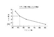
図3は、モータのステップ数(ステータの極歯数×ステータの枚数)と回転ムラとの関係を示すグラフであり、48ステップ以下で回転ムラは4.0%以上となり著しく悪化していることがわかる。
【0019】
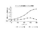
図4は、シールド板の有無と漏洩磁気ノイズとの関係を示したグラフであり、特に40トラックより内周側(79トラック側)ではシールド板が有効であることがわかる。
【0020】
図5は、ステータヨークの位相(極歯の位置)と回転ムラとの関係を示すグラフであり、90°±5°を境に回転ムラは、4.0%以上と著しく悪化することがわかる。
【0021】
このように構成することにより、従来FDD用スピンドルモ−タとしては採用不可能だったクロ−ポ−ル型2相同期モータを回転ムラを抑えて磁気漏洩の少ないモータとしてFDD装置が構成でき、モータ部分のコストダウンとモータ制御回路部分のコストダウンが図れ、FDD装置の大幅な低価格化が実現できた。
【0022】
上記実施の形態では、クローポール型同期モータについて例示したが、本発明は他の形式の同期モータにも同様に適用することができる。
【0023】
また上記実施の形態では漏洩磁束対策として設けた磁気シールド板の内周縁を上向きに起こしたが、外周縁と同じように下向きに起こしてもよい。また、円周上の一部分だけ(特に磁気ヘッド下面部)に設けてもよい。
【0024】
【発明の効果】
以上説明したように、本発明によれば、安価に構成できるクロ−ポ−ル型2相同期モ−タを軸の回転ムラや上下動を抑えた高精度な各種記憶装置のスピンドルモ−タとして採用することができるようになり、モータ専用駆動制御回路の廃止やロータ検出器、速度検出器を用いないオープンループ制御の採用により装置の大幅なコストダウンを図ることができる。
【図面の簡単な説明】
【図1】本発明による記憶装置の一例としてのFDD装置の内部構成を示す斜視図であり、(a)は情報記録用円盤である磁気記録円盤を上方に取り外した状態、(b)は磁気記録円盤を装着した状態を示す。
【図2】図1に示したFDD装置のスピンドルモ−タの縦断面図である。
【図3】本発明によるFDD装置に用いられるスピンドルモータのステップ数(ステータの極歯数×ステータの枚数)と回転ムラとの関係を示すグラフである。
【図4】本発明によるFDD装置に用いられるスピンドルモータにおけるシールド板の有無と漏洩磁気ノイズとの関係を示したグラフである。
【図5】本発明によるFDD装置に用いられるスピンドルモータにおけるステータヨークの位相(極歯の位置)と回転ムラとの関係を示すグラフである。
【符号の説明】
1 フレーム
2 磁気ヘッド
3 アクチュエータ
4 スピンドルモータ
5 磁気記録円盤
6 コントロール回路
11 シールド板
12 ステータ組立体
13 ベース
14 ロータ組立体
15 シャフト
16 軸受
17 ドライブピン
18 ステータヨークA
19 ステータヨークB
20 コイル[0001]
BACKGROUND OF THE INVENTION
The present invention relates to a storage device represented by FDD, HDD, CD-ROM and the like.
[0002]
[Prior art]
This type of storage device includes a chassis on which component parts of the device are mounted and accommodated, a spindle motor that rotationally drives an information recording disk, a magnetic head that reads and writes information on the information recording disk, and this magnetic head. The actuator is driven in the radial direction of the information recording disk, and a control circuit for controlling the operation of the entire apparatus. Among these components, a three-phase brushless DC motor has been conventionally used for a spindle motor that has the highest cost and requires high accuracy because of its high required performance.
[0003]
[Problems to be solved by the invention]
However, the response to the recent price decline has reached the limit, and a motor that can be configured at a lower price is required. However, focusing on the claw pole type two-phase synchronous motor, the motor is basically a stepping motor. The shaft speed has a large speed fluctuation, and the rotating shaft moves up and down depending on the excitation state. Therefore, the smooth rotation required for the spindle motor cannot be obtained, and it has been difficult to adopt it in a satisfactory state. Further, since the motor driving excitation coil is a solenoid coil due to the motor configuration, a large leakage magnetic flux is generated each time the excitation is performed, and this leads to a problem that the S / N of the head output signal deteriorates by interlinking with the magnetic head. was there.
[0004]
The present invention has been made in view of the above points, and suppresses uneven rotation and vertical movement of the shaft, which are problems of the claw pole type two-phase synchronous motor, and suppresses leakage magnetic flux, thereby reducing the cost of the
[0005]
In order to achieve the above object, the present invention rotates a frame, an information recording disk, a head that reads and writes information on the information recording disk, an actuator that drives the head, and the information recording disk. A spindle motor is provided, and the spindle motor forms a stator assembly by stacking a plurality of armature coils sandwiched between two stator yokes each having a pole tooth by bending a soft magnetic steel plate in the motor axial direction. In the storage device comprising a claw pole type synchronous motor having a field rotor made of a permanent magnet provided so as to be opposed to the pole teeth of the stator assembly at a minute interval, the claw pole type synchronous motor comprises : said stator assembly, a rotor assembly comprising a shaft and magnetic-field rotor, a bearing formed by axially supporting the said shaft, and a base, The stator assembly and the bearing are coaxially disposed on the base, and the base, the stator assembly, and the bearing are integrated with a polymer material, and the base is It was fixed to the frame.
[0006]
In addition, the number of basic steps of the claw pole type synchronous motor is preferably 48 steps or more in order to obtain a smooth rotation.
[0007]
The surface of the rotor assembly on which the information recording disk is placed is magnetized to attract and hold the information recording disk.
[0008]
A magnetic shield plate is disposed on the upper surface of the stator assembly, and the magnetic shield plate is provided with raised portions on the outer peripheral edge and the inner peripheral edge in order to improve rigidity.
[0009]
Furthermore, the drive control of the claw-pole type synchronous motor is an open loop system.
[0010]
DETAILED DESCRIPTION OF THE INVENTION
Hereinafter, embodiments of the present invention will be described with reference to the drawings.
[0011]
FIG. 1 is a perspective view showing an internal configuration of an FDD as an example of a storage device according to the present invention, in which (a) is a state in which a magnetic recording disk as an information recording disk is removed upward, and (b) is a magnetic recording disk. The state where is attached.
[0012]
In the figure, 1 is a frame, 2 is a magnetic head for reading and writing, 3 is an actuator for driving the
[0013]
2 is a longitudinal sectional view showing the configuration of the
[0014]
More specifically, on the
[0015]
Next, a
[0016]
Next, as a countermeasure against leakage magnetic flux to the
[0017]
The driving method of the claw pole type two-phase synchronous motor is an open loop control because it operates in synchronization with an external clock because of a synchronous motor. In the open loop control, since no rotor detector and speed detector are used, these feedback loops are unnecessary. Also, since the pulse drive in the ON / OFF switching mode is sufficient, the circuit may be a digital circuit, and has a circuit in the vicinity of the motor like a conventional three-phase brushless motor that is driven and controlled by receiving a weak signal. This eliminates the need to provide a motor drive circuit on the control circuit side for controlling the FDD device, and further allows a motor drive circuit to be housed in the LSI. Therefore, a dedicated drive circuit (drive IC, circuit board, etc.) for the motor is not necessary, and the cost can be greatly reduced in terms of the drive circuit.
[0018]
FIG. 3 is a graph showing the relationship between the number of motor steps (number of stator pole teeth × number of stators) and rotation unevenness, and the rotation unevenness is 4.0% or more and significantly worse at 48 steps or less. I understand.
[0019]
FIG. 4 is a graph showing the relationship between the presence / absence of a shield plate and leakage magnetic noise, and it can be seen that the shield plate is particularly effective on the inner peripheral side (79th track side) from 40 tracks.
[0020]
FIG. 5 is a graph showing the relationship between the stator yoke phase (position of pole teeth) and rotation unevenness, and it can be seen that the rotation unevenness is significantly worse than 4.0% at 90 ° ± 5 °. .
[0021]
By configuring in this way, an FDD device can be configured as a motor with less magnetic leakage by suppressing the rotation unevenness of a cro-pole type two-phase synchronous motor that could not be adopted as a conventional FDD spindle motor. The cost of the motor part and the cost of the motor control circuit part can be reduced, and the price of the FDD device can be greatly reduced.
[0022]
In the above embodiment, the claw pole type synchronous motor is exemplified, but the present invention can be similarly applied to other types of synchronous motors.
[0023]
Moreover, in the said embodiment, although the inner peripheral edge of the magnetic shield board provided as a countermeasure against a leakage magnetic flux was raised upward, you may raise | lower downward like an outer peripheral edge. Further, it may be provided only on a part of the circumference (particularly on the lower surface of the magnetic head).
[0024]
【The invention's effect】
As described above, according to the present invention, a low-speed, two-phase synchronous motor can be configured as a spindle motor for various high-precision storage devices with reduced shaft rotation unevenness and vertical movement. As a result, the cost of the apparatus can be significantly reduced by eliminating the motor dedicated drive control circuit and using the open loop control without using the rotor detector and the speed detector.
[Brief description of the drawings]
FIG. 1 is a perspective view showing an internal configuration of an FDD device as an example of a storage device according to the present invention, in which (a) shows a state in which a magnetic recording disk, which is an information recording disk, is removed upward; The state where the recording disk is installed is shown.
2 is a longitudinal sectional view of a spindle motor of the FDD apparatus shown in FIG. 1. FIG.
FIG. 3 is a graph showing the relationship between the number of steps of the spindle motor used in the FDD device according to the present invention (number of stator pole teeth × number of stators) and rotation unevenness;
FIG. 4 is a graph showing the relationship between the presence / absence of a shield plate and leakage magnetic noise in a spindle motor used in an FDD apparatus according to the present invention.
FIG. 5 is a graph showing the relationship between the phase of the stator yoke (position of pole teeth) and rotation unevenness in the spindle motor used in the FDD device according to the present invention.
[Explanation of symbols]
DESCRIPTION OF
19 Stator yoke B
20 coils
Claims (7)
前記クローポール型同期モータは、前記ステータ組立体と、シャフトと界磁用ロータから成るロータ組立体と、前記シャフトを軸支して成る軸受と、ベースと、から成る構成であって、前記ステータ組立体と前記軸受を同軸に前記ベース上に配設し、前記ベースと前記ステータ組立体と前記軸受とを高分子材料にて一体化して、前記ベースを前記フレームに固定して成ることを特徴とする記憶装置。A frame, an information recording disk, a head for reading and writing to the information recording disk, an actuator for driving the head, and a spindle motor for rotationally driving the information recording disk. A stator assembly is formed by stacking a plurality of armature coils sandwiched between two stator yokes each having pole teeth formed by bending a steel plate in the axial direction of the motor. In a storage device comprising a claw pole type synchronous motor having a field rotor composed of permanent magnets provided so as to face each other at a distance,
The claw pole type synchronous motor includes the stator assembly, a rotor assembly composed of a shaft and a field rotor, a bearing that pivotally supports the shaft, and a base. An assembly and the bearing are coaxially arranged on the base, the base, the stator assembly and the bearing are integrated with a polymer material, and the base is fixed to the frame. A storage device.
Priority Applications (2)
| Application Number | Priority Date | Filing Date | Title |
|---|---|---|---|
| JP16647596A JP3691908B2 (en) | 1996-06-26 | 1996-06-26 | Storage device |
| US08/874,079 US5875069A (en) | 1996-06-26 | 1997-06-12 | Claw-pole synchronous motor for driving a storage device |
Applications Claiming Priority (1)
| Application Number | Priority Date | Filing Date | Title |
|---|---|---|---|
| JP16647596A JP3691908B2 (en) | 1996-06-26 | 1996-06-26 | Storage device |
Publications (2)
| Publication Number | Publication Date |
|---|---|
| JPH1011886A JPH1011886A (en) | 1998-01-16 |
| JP3691908B2 true JP3691908B2 (en) | 2005-09-07 |
Family
ID=15832095
Family Applications (1)
| Application Number | Title | Priority Date | Filing Date |
|---|---|---|---|
| JP16647596A Expired - Fee Related JP3691908B2 (en) | 1996-06-26 | 1996-06-26 | Storage device |
Country Status (2)
| Country | Link |
|---|---|
| US (1) | US5875069A (en) |
| JP (1) | JP3691908B2 (en) |
Families Citing this family (6)
| Publication number | Priority date | Publication date | Assignee | Title |
|---|---|---|---|---|
| TW420347U (en) * | 1999-01-11 | 2001-01-21 | Sunonwealth Electr Mach Ind Co | Transfer system structure of main axis motor for CD-ROM drive |
| US6522498B1 (en) | 1999-11-22 | 2003-02-18 | Seagate Technology Llc | Magnetic shield for flux leakage reduction from spindle motor |
| JP4590714B2 (en) * | 2000-10-23 | 2010-12-01 | パナソニック株式会社 | Brushless motor and manufacturing method thereof |
| US6876114B2 (en) | 2000-12-13 | 2005-04-05 | Seagate Technology Llc | Apparatus for reducing spindle motor magnetic drag |
| US7550890B2 (en) * | 2005-08-23 | 2009-06-23 | Seagate Technology Llc | Motor assembly with an integrated flexible printed circuit |
| TWI373563B (en) * | 2008-06-03 | 2012-10-01 | Sunonwealth Electr Mach Ind Co | Brushless dc motor |
Family Cites Families (2)
| Publication number | Priority date | Publication date | Assignee | Title |
|---|---|---|---|---|
| US5304879A (en) * | 1991-12-07 | 1994-04-19 | Minebea Kabushiki-Kaisha (Minebea Co., Ltd) | Outer rotor motor |
| JP3013288B2 (en) * | 1995-08-31 | 2000-02-28 | ミネベア株式会社 | Stepping motor |
-
1996
- 1996-06-26 JP JP16647596A patent/JP3691908B2/en not_active Expired - Fee Related
-
1997
- 1997-06-12 US US08/874,079 patent/US5875069A/en not_active Expired - Fee Related
Also Published As
| Publication number | Publication date |
|---|---|
| US5875069A (en) | 1999-02-23 |
| JPH1011886A (en) | 1998-01-16 |
Similar Documents
| Publication | Publication Date | Title |
|---|---|---|
| JP3317479B2 (en) | Stepping motor | |
| JP3691908B2 (en) | Storage device | |
| JP4797264B2 (en) | Motor and disk drive device | |
| JP4666803B2 (en) | Magnetic disk unit | |
| JPH07201126A (en) | Spindle motor of disk device | |
| JP2601014B2 (en) | Electric motor | |
| JP2646269B2 (en) | Disk drive | |
| JP3469601B2 (en) | motor | |
| JP2523299Y2 (en) | Disk drive | |
| JPH0315249A (en) | Double-rotor type motor | |
| JP2002325414A (en) | Motor and disk drive device | |
| JP2664237B2 (en) | Disk drive | |
| JP3047591B2 (en) | Optical disk drive | |
| JP2641076B2 (en) | Brushless motor | |
| JPH0229600Y2 (en) | ||
| JPH02214453A (en) | Coil holding structure for motor and double rotor type motor using the same structure | |
| JPH0937496A (en) | Stator structure of rotating electric machine | |
| JPS60118043A (en) | Disc driving motor | |
| EP0433037B1 (en) | Spindle motor and disk drive provided therewith | |
| JPH087462A (en) | Floppy disk drive | |
| JPH06290536A (en) | Disk device | |
| JPH06253518A (en) | Brushless motor | |
| JPH09308205A (en) | Brushless motor and magnet magnetizing device for motor | |
| JPH04345974A (en) | Head positioning mechanism | |
| JPH02219449A (en) | Disc drive |
Legal Events
| Date | Code | Title | Description |
|---|---|---|---|
| A131 | Notification of reasons for refusal |
Free format text: JAPANESE INTERMEDIATE CODE: A131 Effective date: 20050125 |
|
| A521 | Written amendment |
Free format text: JAPANESE INTERMEDIATE CODE: A523 Effective date: 20050325 |
|
| A131 | Notification of reasons for refusal |
Free format text: JAPANESE INTERMEDIATE CODE: A131 Effective date: 20050419 |
|
| A521 | Written amendment |
Free format text: JAPANESE INTERMEDIATE CODE: A523 Effective date: 20050513 |
|
| TRDD | Decision of grant or rejection written | ||
| A01 | Written decision to grant a patent or to grant a registration (utility model) |
Free format text: JAPANESE INTERMEDIATE CODE: A01 Effective date: 20050614 |
|
| A61 | First payment of annual fees (during grant procedure) |
Free format text: JAPANESE INTERMEDIATE CODE: A61 Effective date: 20050617 |
|
| R150 | Certificate of patent or registration of utility model |
Free format text: JAPANESE INTERMEDIATE CODE: R150 |
|
| FPAY | Renewal fee payment (event date is renewal date of database) |
Free format text: PAYMENT UNTIL: 20080624 Year of fee payment: 3 |
|
| FPAY | Renewal fee payment (event date is renewal date of database) |
Free format text: PAYMENT UNTIL: 20090624 Year of fee payment: 4 |
|
| FPAY | Renewal fee payment (event date is renewal date of database) |
Free format text: PAYMENT UNTIL: 20090624 Year of fee payment: 4 |
|
| FPAY | Renewal fee payment (event date is renewal date of database) |
Free format text: PAYMENT UNTIL: 20100624 Year of fee payment: 5 |
|
| FPAY | Renewal fee payment (event date is renewal date of database) |
Free format text: PAYMENT UNTIL: 20100624 Year of fee payment: 5 |
|
| FPAY | Renewal fee payment (event date is renewal date of database) |
Free format text: PAYMENT UNTIL: 20110624 Year of fee payment: 6 |
|
| FPAY | Renewal fee payment (event date is renewal date of database) |
Free format text: PAYMENT UNTIL: 20110624 Year of fee payment: 6 |
|
| FPAY | Renewal fee payment (event date is renewal date of database) |
Free format text: PAYMENT UNTIL: 20120624 Year of fee payment: 7 |
|
| FPAY | Renewal fee payment (event date is renewal date of database) |
Free format text: PAYMENT UNTIL: 20120624 Year of fee payment: 7 |
|
| FPAY | Renewal fee payment (event date is renewal date of database) |
Free format text: PAYMENT UNTIL: 20130624 Year of fee payment: 8 |
|
| R250 | Receipt of annual fees |
Free format text: JAPANESE INTERMEDIATE CODE: R250 |
|
| LAPS | Cancellation because of no payment of annual fees |