JP3689309B2 - Hose storage faucet - Google Patents
Hose storage faucet Download PDFInfo
- Publication number
- JP3689309B2 JP3689309B2 JP2000131201A JP2000131201A JP3689309B2 JP 3689309 B2 JP3689309 B2 JP 3689309B2 JP 2000131201 A JP2000131201 A JP 2000131201A JP 2000131201 A JP2000131201 A JP 2000131201A JP 3689309 B2 JP3689309 B2 JP 3689309B2
- Authority
- JP
- Japan
- Prior art keywords
- hose
- faucet
- guide
- draining member
- cylindrical
- Prior art date
- Legal status (The legal status is an assumption and is not a legal conclusion. Google has not performed a legal analysis and makes no representation as to the accuracy of the status listed.)
- Expired - Fee Related
Links
Images


Landscapes
- Domestic Plumbing Installations (AREA)
Description
【0001】
【発明の属する技術分野】
この発明は吐水ヘッドに繋がれた可撓性のホースがホース収納管に挿通状態に収納されるホース収納式水栓に関する。
【0002】
【従来の技術】
図9はこの種ホース収納式水栓の一例として、キッチン用水栓或いは洗髪洗面用水栓等として広く用いられているシャワー水栓の一例を示している。
同図において200は取付基体としてのカウンターで、このカウンター200に対し、水栓本体202と吐水部204とが離隔した位置において取り付けられている。
【0003】
水栓本体202には水,湯のサプライ管206が接続されており、それらサプライ管206を通じて水,湯が水栓本体202に供給される。
水栓本体202は、供給された水と湯とをハンドル208の操作により所定比率に混合し、その混合水を流出管210を通じて外部に流出する。
【0004】
吐水部204は、吐水ヘッド(シャワーヘッド)212と、その吐水ヘッド212に接続された可撓性のホース214を収納する湾曲形状のホース収納管216とを有している。
吐水ヘッド212は下面に吐水口218を有し、更にその吐水口218からの吐水をシャワー吐水から整流吐水に若しくはその逆に切替操作する切替操作部220を前面に備えており、上記ホース214とともにホース収納管216から引出可能とされている。
尚、222は吐水ヘッド212及びホース収納管216とともに上下動するスライド管で、外周面に雄ねじを有するガイド管224内に摺動可能に挿通されている。
【0005】
この例のシャワー水栓では、吐水ヘッド212を引き出して使用するときにホース214を内部に挿通してその摺動ガイドを行う筒状のホースガイドが、ホース収納管216の先端部に装着されている。
【0006】
【発明が解決しようとする課題】
ところでこの種水栓においては、ホース外面に付着した水の水切りを行うため、筒状の水切部材をホースの外面に嵌合状態に装着することが行われている。
この場合、上記ホースガイドの内径をホース外径に近いものとし、即ちホースの外面とホースガイドの内面との間の隙間を可及的に小さくし、そのホースガイドによって水切りを行うこと、即ちホースガイドに水切部材を兼用させることが考えられる。
【0007】
しかしながらこのようにすると、ホースの端部にこれよりも大径の端部金具を一旦かしめ固定してしまうと、その後においてホースガイドをホースに嵌め合せ、取り付けることができなくなってしまう問題を生ずる。
【0008】
通常、ホースの端部には相手部品との接続等のためにホースよりも大径の端部金具がかしめ固定されるが、このように端部金具を固定してしまうと、ホースガイドに対してこの端部金具を通過させることができず、ホースガイドを後においてホースに取り付け得なくなってしまうのである。
【0009】
従ってこの場合には予めホースにホースガイドを嵌め合せ、取り付けた後において、そのホースの端部に端部金具をかしめ固定せざるを得ず、それらホース,端部金具,ホースガイドを一体のホースアッシー(ホース組付品)として扱わざるを得なくなる。
【0010】
即ち、水栓取付けに際してホース,端部金具,ホースガイドを組み付けて成るホースアッシーを予め用意しておいて、そのホースアッシーを用いて水栓の組付けを行わなければならないといった制約が生じるのであり、このため水栓設置の際の作業性が悪くなる問題を生ずる。
加えてそのホースガイドを別途のものと交換する必要が生じた場合においても、部品交換性が悪いといった問題が生ずる。
他方、ホースガイドとは別に水切部材を設け、それらをホース収納管の端部に装着するようにした水栓も提案されている。
【0011】
図10〜12はその一例を示している(特開平10−147963号)。
図示の例は、水栓本体202からホース収納管216を延び出させ、そこに吐水ヘッド212に接続されたホース214を収納するようになしたもので、図中226はホース214の引出時にその摺動ガイドを行う筒状(この例では円筒形状)のホースガイドである。
【0012】
このホースガイド226には、図12に明かに示しているように弾性片228が設けられていてその弾性片228に係止爪230が設けられ、その係止爪230が、ホース収納管216の側に設けられた係止孔232に弾性的に係止することで、ホースガイド226がホース収納管216に取付固定されるようになっている。
【0013】
図10及び図11において、240はホースガイド226とは別体を成す水切部材であってドーナツ管状をなしており、ホースガイド226の軸方向隣接位置においてホース214に嵌合状態に装着され、ホース214の外面に付着した水の水切りを行う。
【0014】
このように水切部材240をホースガイド226と別に設けた場合において、その水切部材240は適正に水切りを行えるように内径を小さくしておくことが必要であり、従ってこの場合においても水切部材240を予めホース214に嵌め合せた後において、ホース214の端部に端部金具をかしめ固定することが必要となる。
【0015】
またホースガイド226の内径が小さい場合(図示の例ではそのようになっている)には、ホースガイド226もまた端部金具のかしめ固定に先立って予めホース214に嵌合せ状態に装着しておくことが必要となる。
この場合ホースアッシーは、ホース214と、水切部材240と、ホースガイド226と、ホース両端部の端部金具とを組み付けた形で構成される。
【0016】
従ってこの場合においても水栓の設置施工の段階で、そこで始めて水切部材240或いはホースガイド226を独立に組み付けるといったことができず、それらを予めホース214とともにホースアッシーとした上でないと組付けができないといった制約が生じ、上記と同様に水栓の施工作業性が悪くなるとともに、後において水切部材240或いはホースガイド226の部品交換が必要となったとき、その部品交換が容易に行えないといった問題を生ずる。
【0017】
尚、水切部材240をゴム製としておいてその内面をホース214の外面に弾性的に密着させるようになすことも考えられる。
この場合、ホース214の端部に端部金具をかしめ固定した後において、ゴム製の水切部材240を弾性拡径変形させることで端部金具を乗り越えさせ、ホース214に嵌合せ状態に取り付けるといったことも一応可能である。
【0018】
しかしながらこの場合、水切部材240の組付性が十分でなく、更にまたホース214を引き出す際の摺動抵抗が大きくなり、操作感が悪いといった問題を生ずる。
更にまた、水切部材240を部品交換するに際してもその部品交換性が不十分である。
【0019】
【課題を解決するための手段】
本発明のホース収納式水栓はこのような課題を解決するために案出されたものである。
而して請求項1のものは、吐水ヘッドに繋がれた可撓性のホースを、ホース収納管の端部に装着した筒状のホースガイドに挿通した上、該ホース収納管内に挿通状態に収納し、ホース引出時に該ホースガイドにて該ホースを摺動ガイドするようになすとともに、該ホースの外周面に嵌合する状態に設けた筒状の水切部材にて該ホース外面の水切りを行うようになしたホース収納式水栓において、前記水切部材を前記ホースの移動時に円筒部で且つ該円筒部の内径を一定に維持して水切作用するものとなすとともに、該水切部材を周方向に分割し、周方向所定位置の分離位置でその分割体に分離可能となしたことを特徴とする。
【0020】
請求項2のものは、請求項1において、前記複数の分割体の少なくとも2個が薄肉のヒンジにて互いに開閉可能に連繋されていることを特徴とする。
【0021】
請求項3のものは、請求項1において、前記複数の分割体の少なくとも2つが互いに非連繋で完全独立構成とされていることを特徴とする。
【0022】
請求項4のものは、請求項1〜3の何れかにおいて、前記周方向の分離位置で合わされる分割体の一方の周方向端面に係合凸部が、他方の周方向端面に対応する係合凹部が形成されていて、それらが互いに係合するようになしてあることを特徴とする。
【0023】
請求項5のものは、請求項1〜4の何れかにおいて、前記ホースガイドの内径が前記ホースの端部に装着された端部金具の外径よりも大径とされており、該ホースガイド内を該端部金具が軸方向に通過可能となしてあることを特徴とする。
【0024】
【作用及び発明の効果】
上記のように請求項1のものは、筒状をなす水切部材を周方向に分割したもので、この請求項1のホース収納式水栓の場合、水切部材の内径がホース端部に固定された端部金具を通過し得ない小径のものであっても、かかる端部金具をホースに固定した後において、そのホースに水切部材を嵌合せ状態に取り付けることができる。
これにより水栓設置の際の施工性が良好となり、また水切部材を部品交換する必要が生じた場合においても、容易にこれを行うことができる。
【0025】
この場合において、分割体の少なくとも2個を薄肉のヒンジにて互いに開閉可能に連繋しておくことができる(請求項2)。
このようにすれば、分割体がばらばらになってしまってこれを紛失してしまう恐れをなくすことができ、更に分割体同士を合わせて全体の筒状の水切部材を構成するに際してもその作業性が良好となる利点が得られる。
【0026】
請求項3のものは、複数の分割体の少なくとも2つを互いに非連繋で完全独立構成となしたもので、この場合においてもホース端部に端部金具を取付固定した後において、水切部材をホースに嵌合せ状態に装着することができる。
【0027】
請求項4のものは、一対の分割体の一方の周方向端面に係合凸部を、他方の周方向端面に係合凹部を形成してそれらを互いに係合するようになしたもので、このようにしておけば、隣接する分割体を分離位置で合せる際に、それら係合凸部と係合凹部との係合作用に基づいて各分割体のそれぞれの周方向端を位置ずれなく正確に合せることができる。
【0028】
請求項5のものは、ホースガイドの内径をホース端部に装着された端部金具の外径よりも大径となしたもので、このようにしておけば、ホースガイドに対して端部金具を軸方向に通過させることができ、従ってホースの端部に対して端部金具をかしめ固定した後においても、ホースガイドをホースに対し軸方向に挿通し嵌合せ状態に装着することができる。
【0029】
請求項1〜5の発明において、上記水切部材は、ホースガイドの内面に嵌合状態に且つ軸方向に固定状態に装着しておくことができる。
【0030】
【実施例】
次に本発明の実施例を図面に基いて詳しく説明する。
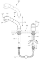
図1〜図5は本発明のホース収納式水栓の一例として、キッチン用水栓或いは洗髪洗面用水栓等として広く用いられているシャワー水栓の例を示したもので、図1中10はその取付基体としてのカウンターで、このカウンター10に対して水栓本体12と吐水部14とが互いに離隔した位置において取付固定されている。
【0031】
水栓本体12には水,湯のサプライ管16が接続されており、それらサプライ管16を通じて水と湯とが水栓本体12に供給される。
水栓本体12は、供給された水と湯とをハンドル18の回転操作により所定比率で混合し、その混合水を流出管20を通じて外部に流出する。
流出管20を通じて流出した混合水は、これに接続された可撓性のホース22を通じて後述の吐水ヘッド(シャワーヘッド)24へと導かれる。
【0032】
吐水部14はその吐水ヘッド24と、これに接続されたホース22を挿通状態に収納する湾曲形状の収納管26とを有している。
このホース収納管26にはスライド管28が一体的に昇降する状態で連結されており、その昇降時にスライド管28が、外周面に雄ねじを有するガイド管30にてスライド案内されるようになっている。
【0033】
吐水ヘッド24は下面に吐水口32を有し、またその前面には吐水口32からの吐水をシャワー吐水から整流吐水に若しくはその逆に切替操作するための切替操作部34を備えており、ホース22とともにホース収納管26から引出可能とされている。
【0034】
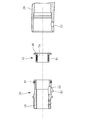
図2及び図3に示しているように、ホース収納管26の先端部には筒状の(この例では円筒形状)ホースガイド36が装着されている。
ホースガイド36は内部にホース22を挿通させ、ホース22が吐水ヘッド24とともにホース収納管26から引き出される際に摺動ガイドを行うもので、ホース収納管26から突出した雄嵌合部38を有している。
ここでホースガイド36とホース収納管26との間はOリング40によって水密にシールされている。
【0035】
一方吐水ヘッド24には雌嵌合部42が形成されており、その雌嵌合部42を雄嵌合部38に嵌合することで、吐水ヘッド24がホース収納管26によりホースガイド36を介して保持されるようになっている。
【0036】
ホースガイド36の後端部には、筒状をなす水切部材43が嵌合状態で装着されている。
この水切部材43は硬質の樹脂製の部材であって、図5及び図6に明らかに示しているように一対の分割体43A,43Bを組み合せて構成してある。
【0037】
これら各分割体43A,43Bは、半円筒部44A,44Bと、その軸方向端に設けられた鍔状部46A,46Bとをそれぞれ有しており、各分割体43A,43Bの各半円筒部44A,44Bを合せることによって円筒部44を構成するようになっている。
また各分割体43A,43Bの鍔状部46A,46Bを合せることによって、正面形状が概略U字状をなす全体の鍔状部46を構成するようになっている。
ここで全体としてU字状をなす鍔状部46は、対応する内面形状のホース収納管26に嵌合することによって、水切部材43全体の回転方向位置を規定する働きをなす。
【0038】
本例において、各分割体43A,43Bは互いに非連繋の完全独立構成とされている。
而して一方の分割体43Aにおける半円筒部44Aの周方向両端面には係合凸部70が設けられており、また他方の分割体43Bにおける半円筒部44Bの周方向両端面には対応する係合凹部72が形成されており、それら係合凸部70と係合凹部72とが互いに係合するようになっている。
【0039】
これら係合凸部70と係合凹部72とは、互いに係合することによって各分割体43A,43Bにおける半円筒部44A,44Bの周方向端を位置決めし、それらが分離面において位置ずれを生じることなく正確に合致させる働きをなす。
【0040】
この水切部材43は、図3に明らかに示しているように円筒部44がホースガイド36に内嵌する状態で、かかるホースガイド36に組み付けられている。
尚、円筒部44の内径はホース22の外径よりも大径とされているが、そのホース22の外径に対し内径が可及的に近いものとされている。即ちホース22の外面と水切部材43の内面との間の隙間が可及的に小さいものとされている。
【0041】
尚ホースガイド36の内径はホース22の端部にかしめ固定された端部金具74の外径よりも大きくされており、その端部金具74がホースガイド36内を通過可能とされている。
一方水切部材43は、その内径が端部金具74に対して小径とされている。
【0042】
ホースガイド36は樹脂製の部材であって、軸方向後半部に弾性片48が設けられている。
弾性片48の先端部には係止爪50が設けられており、この係止爪50が、ホース収納管26側において対応する位置に形成された係止孔52に弾性的に係止することで、ホースガイド36がホース収納管26から抜止めされている。
ここで弾性片48はホース22の引出方向、即ちホースガイド36の抜出方向に延出形成されている。詳しくは弾性片48は、その付根から先端が抜出方向を向くように延出形成されている。
【0043】
本例の水栓の場合、水切部材43の内径がホース端部に固定された端部金具74を通過し得ない小径のものであっても、かかる端部金具74をホース22に固定した後において、そのホース22に水切部材43を嵌合せ状態に取り付けることができる。これにより水栓設置の際の施工性が良好となり、また水切部材43を部品交換する必要が生じた場合においても、容易にこれを行うことができる。
【0044】
また分割体43Aの周方向端面に係合凸部70を、他方の分割体43Bの周方向端面に係合凹部72を形成してそれらを互いに係合するようにしていることから、一対の分割体43A,43Bを分離位置で合せる際にそれら係合凸部70と係合凹部72との係合作用に基づいて、各分割体43A,43Bのそれぞれの周方向端を位置ずれなく正確に合せることができる。
【0045】
本例によれば、ホースガイド36に対して端部金具74を軸方向に通過させることができ、従ってホース22の端部に端部金具74をかしめ固定した後においても、ホースガイド36をホース22に対し軸方向に挿通し嵌合せ状態に装着することができる。
【0046】
以上の例では水切部材43における分割体43A,43Bが非連繋で完全独立構成とされているが、図7に示しているように分割体43A,43Bを薄肉のヒンジ76で連繋した形態で水切部材43を構成することも可能である。
【0047】
このようにすれば、分割体43A,43Bがばらばらになってしまってこれを紛失してしまう恐れをなくすことができ、更に分割体同士を合わせて全体の筒状の水切部材43を構成するに際してもその作業性が良好となる利点が得られる。
【0048】
図8は水切部材の他の例を参考例として示したもので、この例の水切部材78は帯状のばね板材80をスパイラル状に巻いて円筒形状の水切部材78を構成した例である。
この水切部材78は、原形状である縮径状態においてその内径がホース22の外径よりも僅かに大きく、ホース22の外面に対して弾性的に密着しないようになっている。
【0049】
この水切部材78は拡径方向に弾性変形可能であり、そしてその弾性拡径変形によりホース22の端部金具74を通過可能で、これによりホース22に対し外嵌状態でホースガイド36に装着することができる。
【0050】
この例の場合、ホース22を吐水ヘッド24とともにホース収納管26から引き出す際、水切部材78とホース22との間で大きな摩擦抵抗が発生せず、ホース22を軽やかに引き出すことができ、その際の操作感が良好となる。
また水切部材43をホース22に外嵌する状態に装着するに際し、ホース22に端部金具74を取り付けた後においても水切部材78の取付けが可能となる。
【0051】
以上本発明の実施例を詳述したがこれはあくまで一例示であり、本発明は他の種々形態の水栓に適用することが可能であるなど、その主旨を逸脱しない範囲において種々変更を加えた形態で構成可能である。
【図面の簡単な説明】
【図1】 本発明の一実施例であるホース収納式水栓を示す図である。
【図2】 同じ実施例のホースガイドと水切部材を周辺部とともに組付状態で示す図である。
【図3】 同じ実施例のホースガイドと水切部材をホース引出状態で示した図である。
【図4】 同じ実施例のホースガイドと水切部材とホース収納管とを分解した状態で示す図である。
【図5】 同じ実施例のホースガイドと水切部材を周辺部とともに各部材に分解した状態で示す斜視図である。
【図6】 同じ実施例の水切部材の具体的構成を示す図である。
【図7】 本発明の他の実施例における水切部材の構成を示す図である。
【図8】 本発明の参考例としての水切部材の構成を示す図である。
【図9】 従来のホース収納式水栓の一例を示す図である。
【図10】 従来のホース収納式水栓の図9とは異なる例を示す図である。
【図11】 図10のホース収納式水栓を各部材に分解して示す図である。
【図12】 図11におけるホースガイドの取付構造を示す図である。
【符号の説明】
22 ホース
24 吐水ヘッド
36 ホースガイド
43 水切部材
43A,43B 分割体
70 係合凸部
72 係合凹部
74 端部金具
76 ヒンジ
80 ばね部材[0001]
BACKGROUND OF THE INVENTION
The present invention relates to a hose storage faucet in which a flexible hose connected to a water discharge head is housed in a hose housing tube in an inserted state.
[0002]
[Prior art]
FIG. 9 shows an example of a shower faucet widely used as a kitchen faucet or a hair-washing faucet as an example of this type of hose-housing faucet.
In the figure,
[0003]
A water / hot
The
[0004]
The
The
A
[0005]
In the shower faucet of this example, when the
[0006]
[Problems to be solved by the invention]
By the way, in this kind of faucet, in order to drain the water adhering to the outer surface of the hose, a tubular draining member is mounted on the outer surface of the hose in a fitted state.
In this case, the inner diameter of the hose guide is close to the outer diameter of the hose, that is, the gap between the outer surface of the hose and the inner surface of the hose guide is made as small as possible, and draining is performed with the hose guide. It is conceivable that the drainage member is also used as a guide.
[0007]
However, if it does in this way, once an end metal fitting larger diameter than this will be once caulked and fixed to the end part of a hose, the problem that it becomes impossible to fit and attach a hose guide to a hose after that will arise.
[0008]
Normally, an end fitting with a diameter larger than that of the hose is caulked and fixed to the end of the hose for connection to the other part, but if the end fitting is fixed in this way, The end fitting cannot be passed through and the hose guide cannot be attached to the hose later.
[0009]
Therefore, in this case, after fitting and attaching the hose guide to the hose in advance, the end fitting must be caulked and fixed to the end of the hose, and the hose, end fitting and hose guide are integrated into the hose. It must be handled as an assembly (hose assembly).
[0010]
That is, there is a restriction that a hose assembly in which a hose, an end fitting, and a hose guide are assembled is prepared in advance when the faucet is attached, and the faucet must be assembled using the hose assembly. For this reason, there arises a problem that workability at the time of installing the faucet is deteriorated.
In addition, even when the hose guide needs to be replaced with another one, there arises a problem that the component exchangeability is poor.
On the other hand, a faucet has been proposed in which a draining member is provided separately from the hose guide and is attached to the end of the hose storage tube.
[0011]
10 to 12 show an example (Japanese Patent Laid-Open No. 10-147963).
In the illustrated example, the
[0012]
The
[0013]
10 and 11, 240 is a draining member that is separate from the
[0014]
Thus, when the
[0015]
In addition, when the inner diameter of the
In this case, the hose assembly is configured by assembling a
[0016]
Therefore, even in this case, at the stage of installation and installation of the faucet, the
[0017]
It is also conceivable that the draining
In this case, after the end fitting is caulked and fixed to the end of the
[0018]
However, in this case, there is a problem that the assembling property of the draining
In addition, when the
[0019]
[Means for Solving the Problems]
The hose-housing faucet of the present invention has been devised to solve such problems.
Thus, according to the first aspect of the present invention, the flexible hose connected to the water discharge head is inserted into the cylindrical hose guide attached to the end of the hose storage tube, and then inserted into the hose storage tube. The hose guide is slidably guided by the hose guide when the hose is pulled out, and the outer surface of the hose is drained by a cylindrical draining member provided to be fitted to the outer peripheral surface of the hose. In the hose storage faucet configured as described above, the draining member is a cylindrical part when the hose is moved, and maintains the inner diameter of the cylindrical part to be drained, and the draining member is disposed in the circumferential direction. It is divided and can be separated into its divided bodies at a separation position at a predetermined position in the circumferential direction.
[0020]
According to a second aspect of the present invention, in the first aspect, at least two of the plurality of divided bodies are connected to each other by a thin hinge so as to be openable and closable.
[0021]
According to a third aspect of the present invention, in the first aspect, at least two of the plurality of divided bodies are not connected to each other and have a completely independent configuration.
[0022]
According to a fourth aspect of the present invention, in any one of the first to third aspects, the engagement convex portion corresponds to the other circumferential end surface of the divided body that is fitted at the circumferential separation position. A mating recess is formed and they are adapted to engage with each other.
[0023]
According to a fifth aspect of the present invention, in any one of the first to fourth aspects, the inner diameter of the hose guide is larger than the outer diameter of the end fitting attached to the end of the hose. It is characterized in that the end fitting can be passed in the axial direction .
[0024]
[Operation and effect of the invention]
As described above, according to the first aspect of the present invention, the draining member having a cylindrical shape is divided in the circumferential direction. In the case of the hose storage type faucet according to the first aspect, the inner diameter of the draining member is fixed to the end of the hose. Even if the end metal fitting has a small diameter that cannot pass through the end fitting, the drainage member can be fitted and attached to the hose after the end fitting is fixed to the hose.
Thereby, the workability at the time of faucet installation becomes good, and this can be easily performed even when it is necessary to replace the drainage member.
[0025]
In this case, at least two of the divided bodies can be connected to each other by a thin hinge so as to be openable and closable (claim 2).
In this way, it is possible to eliminate the possibility that the divided bodies are separated and lost, and further, the workability can be achieved when the divided bodies are combined to form the entire tubular draining member. The advantage that is good is obtained.
[0026]
According to the third aspect of the present invention, at least two of the plurality of divided bodies are not connected to each other and have a completely independent configuration. Even in this case, after attaching and fixing the end fitting to the end of the hose, It can be fitted in a hose.
[0027]
According to a fourth aspect of the present invention, an engagement convex portion is formed on one circumferential end surface of the pair of divided bodies, an engagement concave portion is formed on the other circumferential end surface, and they are engaged with each other. In this way, when the adjacent divided bodies are brought together at the separation position, the respective circumferential ends of the divided bodies are accurately positioned without misalignment based on the engaging action between the engaging convex portions and the engaging concave portions. Can be adapted.
[0028]
According to the fifth aspect of the present invention, the inner diameter of the hose guide is made larger than the outer diameter of the end fitting attached to the end of the hose. Therefore, even after the end fitting is caulked and fixed to the end portion of the hose, the hose guide can be inserted into the hose in the axial direction and fitted .
[0029]
In the first to fifth aspects of the present invention, the draining member can be attached to the inner surface of the hose guide in a fitted state and in a fixed state in the axial direction.
[0030]
【Example】
Next, embodiments of the present invention will be described in detail with reference to the drawings.
1 to 5 show examples of shower faucets widely used as kitchen faucets or shampoo faucets as an example of the hose storage faucets of the present invention. In the counter as an attachment base, the
[0031]
A water and hot
The
The mixed water flowing out through the
[0032]
The
A
[0033]
The
[0034]
As shown in FIGS. 2 and 3, a tubular (in this example, a cylindrical shape)
The
Here, the
[0035]
On the other hand, a female
[0036]
A
The draining
[0037]
Each of these divided
Further, by combining the hook-
Here, the hook-shaped
[0038]
In this example, each of the divided
Thus, engagement
[0039]
The engaging
[0040]
As shown clearly in FIG. 3, the draining
The inner diameter of the
[0041]
The inner diameter of the
On the other hand, the draining
[0042]
The
A locking
Here, the
[0043]
In the case of the faucet of this example, after the end fitting 74 is fixed to the
[0044]
In addition, since the engagement
[0045]
According to this example, the end fitting 74 can be passed in the axial direction with respect to the
[0046]
In the above example, the
[0047]
In this way, it is possible to eliminate the possibility that the divided
[0048]
FIG. 8 shows another example of the draining member as a reference example. The draining
The draining
[0049]
The draining
[0050]
In the case of this example, when the
Further, when the draining
[0051]
Although the embodiment of the present invention has been described in detail above, this is merely an example, and the present invention can be applied to various other forms of faucets, and various modifications are made without departing from the spirit of the present invention. Can be configured.
[Brief description of the drawings]
FIG. 1 is a view showing a hose storage type faucet according to an embodiment of the present invention.
FIG. 2 is a view showing a hose guide and a draining member of the same embodiment in an assembled state together with a peripheral portion.
FIG. 3 is a view showing a hose guide and a draining member of the same embodiment in a hose pulled out state.
FIG. 4 is a view showing a state in which the hose guide, the draining member, and the hose storage tube of the same embodiment are disassembled.
FIG. 5 is a perspective view showing the hose guide and the draining member of the same embodiment in a state where they are disassembled into members together with the peripheral portion.
FIG. 6 is a diagram showing a specific configuration of the draining member of the same embodiment.
FIG. 7 is a view showing a configuration of a draining member in another embodiment of the present invention.
FIG. 8 is a view showing a configuration of a draining member as a reference example of the present invention.
FIG. 9 is a view showing an example of a conventional hose storage type faucet.
FIG. 10 is a view showing an example different from FIG. 9 of a conventional hose storage type faucet.
FIG. 11 is an exploded view of the hose-accommodating faucet of FIG. 10 into each member.
12 is a view showing a mounting structure of the hose guide in FIG.
[Explanation of symbols]
22
Claims (5)
前記水切部材を前記ホースの移動時に円筒部で且つ該円筒部の内径を一定に維持して水切作用するものとなすとともに、該水切部材を周方向に分割し、周方向所定位置の分離位置でその分割体に分離可能となしたことを特徴とするホース収納式水栓。A flexible hose connected to the water discharge head is inserted into a cylindrical hose guide attached to the end of the hose storage tube, and is stored in the insertion state in the hose storage tube. A hose storage type faucet that slides and guides the hose and drains the outer surface of the hose with a cylindrical draining member that is fitted to the outer peripheral surface of the hose. ,
The draining member is a cylindrical part when the hose is moved and the inner diameter of the cylindrical part is maintained constant to drain the water, and the draining member is divided in the circumferential direction at a separation position at a predetermined position in the circumferential direction. A hose-retaining faucet characterized by being separable into its divided bodies.
Priority Applications (1)
| Application Number | Priority Date | Filing Date | Title |
|---|---|---|---|
| JP2000131201A JP3689309B2 (en) | 2000-04-28 | 2000-04-28 | Hose storage faucet |
Applications Claiming Priority (1)
| Application Number | Priority Date | Filing Date | Title |
|---|---|---|---|
| JP2000131201A JP3689309B2 (en) | 2000-04-28 | 2000-04-28 | Hose storage faucet |
Publications (2)
| Publication Number | Publication Date |
|---|---|
| JP2001311189A JP2001311189A (en) | 2001-11-09 |
| JP3689309B2 true JP3689309B2 (en) | 2005-08-31 |
Family
ID=18640144
Family Applications (1)
| Application Number | Title | Priority Date | Filing Date |
|---|---|---|---|
| JP2000131201A Expired - Fee Related JP3689309B2 (en) | 2000-04-28 | 2000-04-28 | Hose storage faucet |
Country Status (1)
| Country | Link |
|---|---|
| JP (1) | JP3689309B2 (en) |
Families Citing this family (5)
| Publication number | Priority date | Publication date | Assignee | Title |
|---|---|---|---|---|
| JP2005016259A (en) * | 2003-06-27 | 2005-01-20 | San-Ei Faucet Mfg Co Ltd | Stopper made of resin |
| JP2006183388A (en) * | 2004-12-28 | 2006-07-13 | Mym Corp | Discharge pipe |
| JP6362377B2 (en) * | 2014-03-28 | 2018-07-25 | 株式会社ケーブイケー | Shower head support device |
| JP6934631B2 (en) * | 2017-11-30 | 2021-09-15 | パナソニックIpマネジメント株式会社 | Faucet device |
| JP7366554B2 (en) | 2019-02-25 | 2023-10-23 | 株式会社Kvk | Hose unit and faucet |
Family Cites Families (5)
| Publication number | Priority date | Publication date | Assignee | Title |
|---|---|---|---|---|
| JPS6398750U (en) * | 1986-12-15 | 1988-06-27 | ||
| JP2528516Y2 (en) * | 1990-11-15 | 1997-03-12 | 東陶機器株式会社 | Hose drainer for shower equipment |
| JPH0860720A (en) * | 1994-08-25 | 1996-03-05 | Kitamura Gokin Seisakusho:Kk | Draining mechanism in shower holder |
| JPH08270026A (en) * | 1995-03-31 | 1996-10-15 | Toto Ltd | Preventive structure of water in cock provided with shower device |
| JPH09242143A (en) * | 1996-03-06 | 1997-09-16 | Inax Corp | Water supply pipe connecting structure for faucet |
-
2000
- 2000-04-28 JP JP2000131201A patent/JP3689309B2/en not_active Expired - Fee Related
Also Published As
| Publication number | Publication date |
|---|---|
| JP2001311189A (en) | 2001-11-09 |
Similar Documents
| Publication | Publication Date | Title |
|---|---|---|
| CA2688907C (en) | Faucet | |
| EP1272789B1 (en) | Rotatable quick connector | |
| US9062441B2 (en) | Cable overload device | |
| US11143334B2 (en) | Escutcheon | |
| JP2006328674A (en) | Connection structure of water faucet | |
| JP3689309B2 (en) | Hose storage faucet | |
| US20210301507A1 (en) | Wall installation connection box unit with a functional surface body | |
| CA2265627A1 (en) | A rising stem tap of plastic, preferably with a metal threaded insert | |
| JP4987643B2 (en) | Shower head support mechanism | |
| KR102367069B1 (en) | One-touch connection device of the faucet for the sink and the discharge pipe | |
| JP6615563B2 (en) | Structure for connecting two pipes | |
| JPH06191336A (en) | Attachable and detachable rotating anchoring clip for use in vehicle seat cushion and connecting device including said clip | |
| JP2002267071A (en) | Easy release joint | |
| CN210484683U (en) | Quick installation structure of body in tap | |
| JP3711246B2 (en) | One-touch joint | |
| JP2001311192A (en) | Connection structure of tubular body in faucet | |
| JP4335401B2 (en) | Quick fitting | |
| JP2003294185A (en) | Quick pipe disconnect coupling | |
| JP2004011814A (en) | Cylinder valve, and water and hot water mixing faucet using it | |
| CN216045702U (en) | Hidden forward switch angle valve device | |
| JP3711224B2 (en) | Quick fitting | |
| JP3753370B2 (en) | How to install faucets and faucets | |
| JP3678976B2 (en) | Connection structure between water discharge head and water pipe | |
| CN209977380U (en) | Pull-push type tap | |
| JP2006266475A (en) | Quick connector |
Legal Events
| Date | Code | Title | Description |
|---|---|---|---|
| A977 | Report on retrieval |
Free format text: JAPANESE INTERMEDIATE CODE: A971007 Effective date: 20041029 |
|
| A131 | Notification of reasons for refusal |
Free format text: JAPANESE INTERMEDIATE CODE: A131 Effective date: 20041130 |
|
| A521 | Written amendment |
Free format text: JAPANESE INTERMEDIATE CODE: A523 Effective date: 20050131 |
|
| TRDD | Decision of grant or rejection written | ||
| A01 | Written decision to grant a patent or to grant a registration (utility model) |
Free format text: JAPANESE INTERMEDIATE CODE: A01 Effective date: 20050607 |
|
| A61 | First payment of annual fees (during grant procedure) |
Free format text: JAPANESE INTERMEDIATE CODE: A61 Effective date: 20050610 |
|
| R150 | Certificate of patent or registration of utility model |
Free format text: JAPANESE INTERMEDIATE CODE: R150 Ref document number: 3689309 Country of ref document: JP Free format text: JAPANESE INTERMEDIATE CODE: R150 |
|
| FPAY | Renewal fee payment (event date is renewal date of database) |
Free format text: PAYMENT UNTIL: 20080617 Year of fee payment: 3 |
|
| FPAY | Renewal fee payment (event date is renewal date of database) |
Free format text: PAYMENT UNTIL: 20090617 Year of fee payment: 4 |
|
| FPAY | Renewal fee payment (event date is renewal date of database) |
Free format text: PAYMENT UNTIL: 20100617 Year of fee payment: 5 |
|
| FPAY | Renewal fee payment (event date is renewal date of database) |
Free format text: PAYMENT UNTIL: 20100617 Year of fee payment: 5 |
|
| FPAY | Renewal fee payment (event date is renewal date of database) |
Free format text: PAYMENT UNTIL: 20110617 Year of fee payment: 6 |
|
| S111 | Request for change of ownership or part of ownership |
Free format text: JAPANESE INTERMEDIATE CODE: R313111 |
|
| FPAY | Renewal fee payment (event date is renewal date of database) |
Free format text: PAYMENT UNTIL: 20110617 Year of fee payment: 6 |
|
| R350 | Written notification of registration of transfer |
Free format text: JAPANESE INTERMEDIATE CODE: R350 |
|
| FPAY | Renewal fee payment (event date is renewal date of database) |
Free format text: PAYMENT UNTIL: 20120617 Year of fee payment: 7 |
|
| FPAY | Renewal fee payment (event date is renewal date of database) |
Free format text: PAYMENT UNTIL: 20120617 Year of fee payment: 7 |
|
| FPAY | Renewal fee payment (event date is renewal date of database) |
Free format text: PAYMENT UNTIL: 20130617 Year of fee payment: 8 |
|
| FPAY | Renewal fee payment (event date is renewal date of database) |
Free format text: PAYMENT UNTIL: 20140617 Year of fee payment: 9 |
|
| LAPS | Cancellation because of no payment of annual fees |