JP3688872B2 - Piercing and manufacturing method thereof - Google Patents
Piercing and manufacturing method thereof Download PDFInfo
- Publication number
- JP3688872B2 JP3688872B2 JP32679497A JP32679497A JP3688872B2 JP 3688872 B2 JP3688872 B2 JP 3688872B2 JP 32679497 A JP32679497 A JP 32679497A JP 32679497 A JP32679497 A JP 32679497A JP 3688872 B2 JP3688872 B2 JP 3688872B2
- Authority
- JP
- Japan
- Prior art keywords
- head
- pin
- brazing material
- piercing
- brazed
- Prior art date
- Legal status (The legal status is an assumption and is not a legal conclusion. Google has not performed a legal analysis and makes no representation as to the accuracy of the status listed.)
- Expired - Fee Related
Links
Images




Landscapes
- Adornments (AREA)
Description
【0001】
【発明の属する技術分野】
本発明はピアスおよびその製造方法に関し、特にピンをセラミック部材で形成したピアスおよびその製造方法に関する。
【0002】
【従来の技術及び発明が解決しようとする課題】
従来、ピアスは、に示すように、ピン11の一端部に頭部12を設け、この頭部12に宝飾品13などを装着して構成されていた。このピン11は、例えば金(K18)、表面に金(K18)メッキを施したステンレス鋼、アルミナ(A12O3)、ジルコニア(ZrO2)、あるいはサファイアなどで形成され、頭部12は金(K18)や表面に金(K24)メッキを施したステンレス鋼などで形成される。
【0003】
また、ピン11と頭部12を金やステンレス鋼などで形成する場合、ピン11と頭部12を一体に形成したり、溶接やロー付けによって接合され、ピン11をアルミナ(A12O3)、ジルコニア(ZrO2)、或いはサファイアなどで形成して頭部12を金(K18)やステンレス鋼などで形成する場合、頭部12に孔を形成してこの孔にピン11の一端部を挿入してエポキシ系接着剤やアクリル系接着剤などで接着していた。
【0004】
ところが、この従来のピアスでは、ピン11または頭部12に金(K18)や表面に金(K24)メッキを施したステンレス鋼などで形成する場合、金は貴金属で安定な金属であるが、人体からの発汗などによって、生体中ではやはり多少の腐食が見られ、生体アレルギーを惹起するとともに、高価になるという問題があった。特に、ピン11と頭部12を溶接やロー付けなどで接合すると、この溶接部やロー付け部からの腐食が激しく、生体アレルギーを起こしやすい。
【0005】
また、ピン11と頭部12をエポキシ系接着剤やアクリル系接着剤などで接着する場合、接着された部位は、ピアスを付けたり外したりするたびに繰り返して引っ張り加重や圧縮加重を受け、またピン11には回転の力も加わることから、接着剤が剥がれるという問題があった。さらに、人体からの発汗で接着剤が劣化し、この劣化した接着剤が簡単に剥がれるという問題もあった。
【0006】
そこで、本出願人は、実願平4−85981号において、に示すように、ピン11と頭部14をセラミック部材で形成するとともに、頭部14に孔15を設け、この孔15にピン11の一端部を挿着して頭部14とピン11をガラス熔着したり、焼きばめすることによって、頭部14をピン11に固定することを提案した。
【0007】
このように、ピン11と頭部14の双方をセラミック部材で形成すると、人体に全く為害性がなくなると共に、ピン11と頭部14をガラス熔着や焼きばめで固定すると、ピン11と頭部14を強固に固定することができ、この接合部が人体からの発汗などによって腐食することもないという利点を有する。
【0008】
ところが、頭部14をセラミック部材で形成すると、この頭部14に装飾や形状的な変化を付けることが困難になるという問題があった。
【0009】
本発明はこのような従来技術の問題点に鑑みてなされたものであり、生体アレルギーが発生することを解消するとともに、頭部に装飾や形状的な変化を付けることが困難であるという従来の問題点を解消したピアスを提供することを目的とする。
【0010】
また、生体アレルギーの発生を極力低減できると共に、装飾や形状的な変化を有する頭部をピンにより安定して固定できるピアスの製造方法を提供することを目的とする。
【0011】
【課題を解決するための手段】
上記目的を達成するために、請求項1に係るピアスでは、ピンの一端部に頭部を取り付けて成るピアスにおいて、前記ピンをセラミック部材で形成すると共に、前記ピンの頭部取り付け部を広幅に形成して、この頭部取り付け部に金属化部を断面凸状に形成し、この金属化部に前記頭部をロー付けした。
【0012】
また、請求項2に係るピアスの製造方法によれば、セラミック部材から成るピンの一端部に金属化部を断面凸状に形成して、この金属化部に頭部をロー付けするピアスの製造方法において、前記ロー材を前記ピンの金属化部にあらかじめ取着しておき、しかる後、前記ロー材を溶融固化させることによって前記頭部を前記ピンの金属化部にロー付けする。
【0013】
【発明の実施の形態】
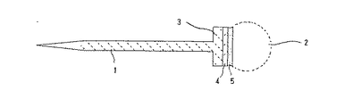
以下、請求項1に係るピアスの一実施形態を詳細に説明する。は、請求項1に係るピアスの参考例を示す図であり、1はピン、2は頭部、3は頭部取り付け部、4は金属化部、5はロー材である。
【0014】
前記ピン1は、例えば直径φ0.6〜1.1mmなどに形成される。このピアスを耳たぶに孔を開けるためのピアスとして用いる場合は、ピン1の先端部を尖鋭に形成する。このピン1は例えばジルコニア質焼結体やアルミナ質焼結体などのセラミック部材から成る。ジルコニア質焼結体の曲げ強度は、10000〜20000kg/cm2であり、極めて折れにくい反面、着色しにくいという問題がある。一方、アルミナ質焼結体は、曲げ強度は2500〜5000kg/cm2でジルコニア質焼結体よりも小さいが、着色顔料を添加した焼結体を得やすい。したがって、曲げ強度を優先させる場合はジルコニア質焼結体で形成すると共に、装飾効果を優先させる場合はアルミナ質焼結体で形成する。このようなジルコニア質焼結体には、例えば酸化イットリウム(Y2O3)、酸化カルシウム(CaO)、あるいは酸化マグネシウム(MgO)などの部分安定化剤を少量添加したものなどがあり、アルミナ質焼結体には、焼結助剤として酸化マグネシウム(MgO)、酸化カルシウム(CaO)、あるいはシリカ(SiO2)などを少量添加したものなどがある。このようなジルコニア質焼結体やアルミナ質焼結体は、所望の原料粉末に一次的結合剤などを添加して、加圧成形法や射出成形法などで生セラミック体を形成し、この生セラミック体を1400〜1700℃程度の温度で焼成して研磨することにより形成される。
【0015】
このピン1の一方端には、頭部取り付け部3が広幅に形成されている。頭部取り付け部3を広幅に形成すると、後述するように頭部2を強固にロー付けできると共に、人体の耳たぶが金属化部4や頭部2に接触しなくなり、生体アレルギーを防止できる。また、この頭部取り付け部3の先端部側は平面状に形成される。この平面部はφ1〜10mm程度、通常は3mm程度にする。この頭部取り付け部3の先端部側に平面部を設けると、耳たぶの孔に皮膚が形成されないうちに、頭部取り付け部3や頭部2が孔に埋没したり、頭部取り付け部3や頭部2が耳たぶの孔を拡げるように作用することがなく、好適である。
【0016】
このピン1の頭部取り付け部3には、金属化部4が形成されている。この金属化部4は、例えばMo−Mnなどから成る。この金属化部4は、ピン1を形成するための生セラミック体にMo−Mnなどを主成分とするペーストを厚み50〜100μm程度に塗布して生セラミック体と同時に焼成することにより、セラミック焼結体と一体に形成する。この金属化部4の表面には、この金属化部4の腐食を防止するとともに、ロー付けを良好に行うことができるようにするために、ニッケルメッキと金メッキの二層のメッキ層が形成される。
【0017】
この金属化部4に頭部2がロー材5でロー付けされる。ロー材5としては、Geを含有するAuロー材、Cuを含有するAgロー材、ハンダなどがある。このロー材5の表面には、必要に応じてこれらのロー材5の腐食を防止するために、金メッキ層やニッケルメッキと金メッキの二層のメッキ層を形成してもよい。
【0018】
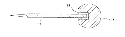
図2は、請求項1に係るピアスの一実施形態を示す図である。請求項1に係るピアスでは、ピン1の頭部取り付け部3に金属化部4を断面凸状に形成する。このように、ピン1の頭部取り付け部3に金属化部4を断面凸状に形成すると、この金属化部4に頭部2をAuロー材などで接合する場合に、このAuロー材が金属化部4と頭部2との対峙部分だけでなく、金属化部4と頭部2との対特部分の側方にも回り込むことから、この金属化部4に頭部2を極めて強固に接合できる。
【0019】
次に、請求項2に係るピアスの製造方法をに基づいて説明する。このピアスの製造方法では、ロー材5をピン1の金属化部4にあらかじめ取着しておき、しかる後、頭部2をロー材5に当接させてこのロー材5を溶融固化させることによってロー付けする。
【0020】
つまり、ピン1と頭部2をロー付けする場合、一般には頭部2のロー付け部に板状または粉状のロー材5を置いて、ピン1をこのロー材5部分に押し付けながら加熱溶融させることによってロー付けしたり((a)(b)参照)、頭部2とピン1を近接させて棒状のロー材5を供給しながら加熱溶融させることによってロー付けする((c)参照)が、いずれの場合も、ロー材5の供給とロー付け作業を同時に行うことから、ロー付けの作業性が悪く、ロー材5の供給量によってロー付け強度がばらついたり、頭部2が異形状の場合は、ロー材5を置きにくく、ロー材5の供給量が安定しないという問題があった。
【0021】
そこで、請求項2に係るピアスの製造方法では、ピン1の金属化部4にロー材5をあらかじめ取着しておき、しかる後、頭部2をロー材5に当接させてロー材5を溶融固化させるようにした。金属化部4へのロー材5の取着は、多数のピン1をそれぞれの金属化部4が上面を向くように治具(不図示)に挿着して、このピン1の金属化部4にペースト状のロー材を厚み0.05〜1mm程度にスクリーン印刷したり、厚み0.05〜1mm程度の板状のロー材をプレス加工機で所定の大きさに打ち抜いて、ピン1の金属化部4に載置して仮溶着することによって行われる。なお、このロー付け方法においても、ピン1の頭部取り付け部3は広幅に形成することが望ましい。
【0022】
このように、ピン1の金属化部4にロー材5をあらかじめ取着すると、そのロー材5の供給量が正確にコントロールできる。したがって、ロー付けされる頭部2の形状や大きさに応じたロー材5をあらかじめ選定できると共に、ロー付けされる頭部も種々のバリエーションのものから選択できる。さらに、人体に為害性のないセラミック部材でピン1を形成して、このピン1の金属化部4にロー材5をあらかじめ取着しておくと、このピン自体で独立した商品の取引対象となり、顧客が独自に用意した頭部2を顧客がロー付けでき、ピン1自体で商品価値を持たせることができるようになる。
【0023】
【実施例】
直径0.6mm、長さ8mmのジルコニア質焼結体から成るピン1の先端部に直径3mmの頭部取り付け部3を設け、この頭部取り付け部3にMo−Mnから成る金属化部4を形成して、この金属化部4とAu/12Geロー材、K14ロー材、K9ロー材を用いて頭部2をロー付けし、この頭部2を固定した状態で、この頭部2から8mm離間したピン1の一点に片端加重を加えて、ロー付け部分の剥離状況とピン1の破損状況を調べた。なお、加重速度は−5mm/minである。Au/12Geロー材、K14ロー材、K9ロー材でロー付けしたものをそれぞれ5個づつ、計15個用意して実験を行った。
【0024】
その結果、ピン1が破損するよりも先にロー付け部分が剥離したものは、Au/12Geロー材でロー付けしたものの1個のみであり、他の14個は全てロー付け部分の剥離はなく、強固にロー付けされていることが確認できた。
【0025】
【発明の効果】
以上のように、請求項1に係るピアスによれば、ピンをセラミック部材で形成すると共に、このピンの頭部取り付け部を広幅に形成して、この頭部取り付け部に金属化部を断面凸状に形成し、この金属化部に上記頭部をロー付けしたことから、生体アレルギーが発生せず、頭部をピンに強固に接合できると共に、接合できる頭部の選択の自由度が拡大し、頭部に装飾や形状的な変化を付けることができる。
【0026】
また、請求項2に係るピアスの製造方法によれば、断面凸状のピンの金属化部にロー材をあらかじめ取着しておき、しかる後、金属化部と頭部をロー付けすることから、頭部をピンに安定してロー付けできるようになり、ロー付け作業が安定すると共に、ロー付け強度も安定する。
【図面の簡単な説明】
【図1】 請求項1に係るピアスの参考例を示す図である。
【図2】 請求項1に係るピアスの一実施形態を示す図である。
【図3】 請求項2に係るピアスの製造方法の一実施形態を示す図である。
【図4】 従来のピアスを示す図である。
【図5】 従来の他のピアスを示す図である。
【図6】 従来のピアスの製造方法を説明するための図である。
【符号の説明】
1・・・ピン、2・・・頭部、3・・・頭部取り付け部、4・・・金属化部、5・・・ロー材[0001]
BACKGROUND OF THE INVENTION
The present invention relates to a pierced earring and a manufacturing method thereof, and more particularly to a pierced earring having a pin formed of a ceramic member and a manufacturing method thereof.
[0002]
[Prior art and problems to be solved by the invention]
Conventionally, as shown in the figure, a pierce is configured by providing a
[0003]
When the
[0004]
However, in this conventional earring, when the
[0005]
Further, when the
[0006]
Therefore, as shown in Japanese Patent Application No. Hei 4-85981, the present applicant forms the
[0007]
In this way, if both the
[0008]
However, when the
[0009]
The present invention has been made in view of such problems of the prior art, and eliminates the occurrence of biological allergies and makes it difficult to add decoration and shape changes to the head. The purpose is to provide piercings that solve the problems.
[0010]
It is another object of the present invention to provide a method of manufacturing a piercing that can reduce the occurrence of biological allergy as much as possible and can stably fix a head having decoration or shape change with a pin.
[0011]
[Means for Solving the Problems]
In order to achieve the above object, in the piercing according to
[0012]
According to the method for manufacturing a piercing according to
[0013]
DETAILED DESCRIPTION OF THE INVENTION
Hereinafter, an embodiment of the earring according to
[0014]
The
[0015]
At the one end of the
[0016]
A metallized portion 4 is formed on the
[0017]
The
[0018]
FIG. 2 is a view showing an embodiment of the piercing according to
[0019]
Next, a method for manufacturing a piercing according to
[0020]
That is, when the
[0021]
Therefore, in the piercing manufacturing method according to
[0022]
Thus, if the brazing material 5 is attached in advance to the metallized portion 4 of the
[0023]
【Example】
A
[0024]
As a result, the brazing part peeled off before the
[0025]
【The invention's effect】
As described above, according to the piercing according to the first aspect, the pin is formed of a ceramic member, the head mounting portion of the pin is formed wide, and the metallized portion is protruded in cross section on the head mounting portion. Since the above-mentioned head is brazed to this metallized part, biological allergy does not occur, the head can be firmly joined to the pin, and the degree of freedom of selection of the head that can be joined is expanded. The head can be decorated and shaped.
[0026]
Moreover, according to the manufacturing method of the piercing according to
[Brief description of the drawings]
FIG. 1 is a diagram showing a reference example of piercing according to
FIG. 2 shows an embodiment of a piercing according to
FIG. 3 is a view showing an embodiment of a piercing manufacturing method according to
FIG. 4 is a diagram showing a conventional piercing.
FIG. 5 is a diagram showing another conventional piercing.
FIG. 6 is a diagram for explaining a conventional method of manufacturing a piercing.
[Explanation of symbols]
DESCRIPTION OF
Claims (2)
Priority Applications (1)
| Application Number | Priority Date | Filing Date | Title |
|---|---|---|---|
| JP32679497A JP3688872B2 (en) | 1996-12-25 | 1997-11-27 | Piercing and manufacturing method thereof |
Applications Claiming Priority (3)
| Application Number | Priority Date | Filing Date | Title |
|---|---|---|---|
| JP34637596 | 1996-12-25 | ||
| JP8-346375 | 1996-12-25 | ||
| JP32679497A JP3688872B2 (en) | 1996-12-25 | 1997-11-27 | Piercing and manufacturing method thereof |
Publications (2)
| Publication Number | Publication Date |
|---|---|
| JPH10234436A JPH10234436A (en) | 1998-09-08 |
| JP3688872B2 true JP3688872B2 (en) | 2005-08-31 |
Family
ID=26572294
Family Applications (1)
| Application Number | Title | Priority Date | Filing Date |
|---|---|---|---|
| JP32679497A Expired - Fee Related JP3688872B2 (en) | 1996-12-25 | 1997-11-27 | Piercing and manufacturing method thereof |
Country Status (1)
| Country | Link |
|---|---|
| JP (1) | JP3688872B2 (en) |
-
1997
- 1997-11-27 JP JP32679497A patent/JP3688872B2/en not_active Expired - Fee Related
Also Published As
| Publication number | Publication date |
|---|---|
| JPH10234436A (en) | 1998-09-08 |
Similar Documents
| Publication | Publication Date | Title |
|---|---|---|
| CN100407078C (en) | Exterior member for wristwatch and method of manufacturing the same | |
| EP2884865B1 (en) | A brazed joint for attachment of gemstones | |
| WO2006032035A1 (en) | Method of attaching a solder element to a contact and the contact assembly formed thereby | |
| US6112551A (en) | Setting metallic parts for setting a facet cut precious stone | |
| JPH10234436A (en) | Piercing and manufacturing method thereof | |
| JP2000014416A (en) | Piercing and manufacturing method thereof | |
| JP2942805B2 (en) | Manufacturing method of composite precious metal accessories | |
| EP1176128A3 (en) | Composite member comprising bonded different members and method for making the composite member | |
| US3712079A (en) | Ring of two precious metal parts, one overlapping and embedding the other along the ring band portion | |
| JPH11178619A (en) | Piercing method | |
| JPH0648410U (en) | Earrings | |
| JP2696395B2 (en) | Electrode manufacturing method | |
| JP2002010813A (en) | Attachment pin mounting structure | |
| JPH10179220A (en) | Earrings | |
| JP7378862B1 (en) | How to install piercing posts, earrings and piercing posts | |
| GB2202728A (en) | Earring | |
| JP2713450B2 (en) | Bonding method of metal material containing oxide | |
| JPS59101787A (en) | Method of producing composite unit of terminal to be implanted to circuit board with soldering material | |
| JPH06178706A (en) | Earrings | |
| CA2099201C (en) | Ball earring process and construction | |
| JP6777709B2 (en) | How to join precious stones and metals | |
| JP3245142U (en) | earrings | |
| JP2023538059A (en) | wire bonding capillary | |
| JPH07327716A (en) | Piercing and its manufacturing method | |
| JP3033358U (en) | Earrings |
Legal Events
| Date | Code | Title | Description |
|---|---|---|---|
| A977 | Report on retrieval |
Free format text: JAPANESE INTERMEDIATE CODE: A971007 Effective date: 20040401 |
|
| A131 | Notification of reasons for refusal |
Free format text: JAPANESE INTERMEDIATE CODE: A131 Effective date: 20040615 |
|
| A521 | Written amendment |
Free format text: JAPANESE INTERMEDIATE CODE: A523 Effective date: 20040812 |
|
| TRDD | Decision of grant or rejection written | ||
| A01 | Written decision to grant a patent or to grant a registration (utility model) |
Free format text: JAPANESE INTERMEDIATE CODE: A01 Effective date: 20050607 |
|
| A61 | First payment of annual fees (during grant procedure) |
Free format text: JAPANESE INTERMEDIATE CODE: A61 Effective date: 20050609 |
|
| R150 | Certificate of patent or registration of utility model |
Free format text: JAPANESE INTERMEDIATE CODE: R150 |
|
| FPAY | Renewal fee payment (event date is renewal date of database) |
Free format text: PAYMENT UNTIL: 20090617 Year of fee payment: 4 |
|
| FPAY | Renewal fee payment (event date is renewal date of database) |
Free format text: PAYMENT UNTIL: 20090617 Year of fee payment: 4 |
|
| FPAY | Renewal fee payment (event date is renewal date of database) |
Free format text: PAYMENT UNTIL: 20100617 Year of fee payment: 5 |
|
| FPAY | Renewal fee payment (event date is renewal date of database) |
Free format text: PAYMENT UNTIL: 20110617 Year of fee payment: 6 |
|
| FPAY | Renewal fee payment (event date is renewal date of database) |
Free format text: PAYMENT UNTIL: 20120617 Year of fee payment: 7 |
|
| FPAY | Renewal fee payment (event date is renewal date of database) |
Free format text: PAYMENT UNTIL: 20120617 Year of fee payment: 7 |
|
| FPAY | Renewal fee payment (event date is renewal date of database) |
Free format text: PAYMENT UNTIL: 20130617 Year of fee payment: 8 |
|
| LAPS | Cancellation because of no payment of annual fees |