JP3688105B2 - Video switching device and video switching equipment using the video switching device - Google Patents
Video switching device and video switching equipment using the video switching device Download PDFInfo
- Publication number
- JP3688105B2 JP3688105B2 JP30227897A JP30227897A JP3688105B2 JP 3688105 B2 JP3688105 B2 JP 3688105B2 JP 30227897 A JP30227897 A JP 30227897A JP 30227897 A JP30227897 A JP 30227897A JP 3688105 B2 JP3688105 B2 JP 3688105B2
- Authority
- JP
- Japan
- Prior art keywords
- video
- camera
- input
- signal
- video signal
- Prior art date
- Legal status (The legal status is an assumption and is not a legal conclusion. Google has not performed a legal analysis and makes no representation as to the accuracy of the status listed.)
- Expired - Fee Related
Links
Images


Description
【0001】
【発明の属する技術分野】
本発明は、複数台のカメラ映像を順次切り換えて映像記録装置に記録する監視システムなどに使用される映像切換装置、特に複数台のカメラを映像ケーブル1本に接続するときに使用される映像切換装置に関するものである。
【0002】
【従来の技術】
従来、複数台のカメラからの映像を映像切換装置に接続し、映像切換装置にて順次カメラの映像出力を切り換え、映像記録装置に記録する監視システムでは、カメラ台数分の映像用ケーブルを映像切換装置に接続している。また、各カメラの同期を合わせる場合には、同期を合わせる信号を伝送するカメラ台数分のケーブルを接続している。
【0003】
また、同一映像ケーブル上に複数台のカメラを接続する場合は、各カメラに各カメラの映像タイミングを制御するコントローラをその制御信号を送る制御用ケーブルにより接続し、各カメラは前記コントローラからの制御に従い映像出力をオン/オフしている。
【0004】
【発明が解決しようとする課題】
しかしながら、上記従来の各カメラから映像用ケーブルを映像切換装置に接続する監視システムでは、カメラの台数分の映像用ケーブルが必要であり、さらに各カメラの同期を合わせる場合には、同期を合わせるカメラ台数分のケーブルも必要となるという問題があった。また、従来のほとんどの映像切換装置のカメラ入力は8入力又は16入力であり、少数カメラの監視システムやカメラの増設に対応しにくいという問題があった。
【0005】
また、同一映像ケーブル上に複数台カメラを接続する監視システムでは、各カメラの映像タイミングを制御するコントローラとその制御信号を送る制御用ケーブルが必要であり、かつ、各カメラに前記コントローラからの制御にしたがい映像出力をオン/オフする制御機能が必要であるという問題もあった。
【0006】
本発明は、このような監視システムなどに使用される映像切換装置において、同一映像用ケーブル上で複数台のカメラを順次切り換えることができ、さらに少数カメラの監視システムやカメラの増設にも容易に対応できることを目的とする。
【0007】
【課題を解決するための手段】
本発明の映像切換装置においては、外部からの映像信号を入力する第1映像入力手段と、前記第1映像入力手段により入力された映像信号を出力する第1映像出力手段と、映像切換タイミング情報を設定する設定手段と、前記設定手段によって予め設定された映像切換タイミング情報と前記第1映像入力手段により入力された映像信号を基に切換タイミング信号を形成する切換タイミング手段と、外部からの映像信号を入力する第2映像入力手段と、前記第2映像入力手段により入力された映像信号と第1映像入力手段により入力された映像信号とを前記切換タイミング信号にしたがって切り換える切換手段と、その切り換えた映像信号を出力する第2の映像出力手段とを備えたことを特徴としたものである。
【0008】
この本発明によれば、同一映像用ケーブル上で複数台のカメラを順次切り換えることができ、さらに少数カメラの監視システムやカメラの増設にも容易に対応できる映像切換装置が得られる。
【0009】
【発明の実施の形態】
本発明の請求項1に記載の発明は、外部からの映像信号を入力する第1映像入力手段と、前記第1映像入力手段により入力された映像信号を出力する第1映像出力手段と、映像切換タイミング情報を設定する設定手段と、前記設定手段によって予め設定された映像切換タイミング情報と前記第1映像入力手段により入力された映像信号を基に切換タイミング信号を形成する切換タイミング手段と、外部からの映像信号を入力する第2映像入力手段と、前記第2映像入力手段により入力された映像信号と第1映像入力手段により入力された映像信号とを前記切換タイミング信号にしたがって切り換える切換手段と、その切り換えた映像信号を出力する第2の映像出力手段とを備えたことを特徴としたものであり、
第1映像入力手段は外部からの映像信号を入力し、この入力された映像信号は第1映像出力手段より出力され、また切換タイミング手段は、設定手段に予め設定された映像切換タイミング情報と第1映像入力手段により入力された映像信号を基に切換タイミング信号を形成し、切換手段は、この切換タイミング信号にしたがって、第2映像入力手段により入力された映像信号と第1映像入力手段により入力された映像信号とを切り換え、この切り換えられた映像は、第2映像出力手段より出力されるという作用を有する。
【0010】
請求項2に記載の発明は、外部からの映像信号を入力する映像入力手段と、映像を識別するために映像に書き込むカメラ番号の書き込みタイミング情報と識別の必要な映像数を設定する設定手段と、前記設定手段によって予め設定された情報と前記映像入力手段により入力された映像信号を基にカメラ番号書き込みタイミング信号を形成するタイミング手段と、前記映像入力手段により入力された映像信号に前記タイミング信号にしたがって順に前記映像数までのカメラ番号を書き込むID書き込み手段と、前記そのカメラ番号が書き込まれた映像信号を出力する映像出力手段とを備えたことを特徴としたものであり、
映像入力手段は外部からの映像信号を入力し、またタイミング手段は、予め設定手段に設定されたカメラ番号書き込みタイミング情報とカメラ台数と映像入力手段により入力された映像信号を基にカメラ番号書き込みタイミング信号を形成し、ID書き込み手段は、このカメラ番号書き込みタイミング信号にしたがって映像入力手段により入力された映像信号にカメラ番号を書き込み、映像出力手段はこのカメラ番号が書き込まれた映像を出力するという作用を有する。
【0011】
請求項3に記載の発明は、外部からの映像信号を入力する第1映像入力手段と、前記第1映像入力手段により入力された映像信号を出力する第1映像出力手段と、映像を識別するために映像信号に書き込まれたカメラ番号の何番目のカメラ番号を識別するかを設定する設定手段と、前記第1映像入力手段により入力された映像信号に書き込まれたカメラ番号を読み出すID読み出し手段と、前記設定手段によって予め設定されたカメラ番号と、前記ID読み出し手段により読み出されたカメラ番号を基に切換タイミング信号を形成する切換タイミング手段と、外部からの映像信号を入力する第2映像入力手段と、前記第2映像入力手段により入力された映像信号と前記第1映像入力手段により入力された映像信号とを前記切換タイミング信号により切り換える切換手段と、その切り換えた映像信号を出力する第2映像出力手段とを備えたことを特徴としたものであり、
第1映像入力手段は外部からの映像信号を入力し、第1映像出力手段は第1映像入力手段により入力された映像信号を出力し、また設定手段によって予め設定された認識するカメラ番号と、ID読み出し手段により読み出された、第1映像入力手段により入力された映像信号に書き込まれたカメラ番号を基に、切換タイミング手段は切換タイミング信号を形成し、切換手段は、この切換タイミング信号により第2映像入力手段により入力された映像信号と第1映像入力手段により入力された映像信号と切り換え、第2の映像出力手段は、その切り換えた映像信号を出力するという作用を有する。
【0012】
請求項4に記載の発明は、複数台のカメラを同一映像ケーブル上に接続するとき、第1のカメラに請求項2記載の映像切換装置を接続し、第2のカメラ以降に請求項3記載の映像切換装置を接続することを特徴としたものであり、
同一映像ケーブル上に接続された第1のカメラ1、第2のカメラ、第2のカメラ以降のカメラからの映像信号が書き込みタイミング情報にしたがって順に切り換えられて出力されるという作用を有する。
【0013】
請求項5に記載の発明は、外部からの映像信号を入力する第1映像入力手段と、前記第1映像入力手段により入力された映像信号を出力する第1映像出力手段と、映像を識別するための映像信号に書き込むカメラ番号の書き込みタイミング情報と識別の必要な映像数、および映像信号に書き込まれたカメラ番号の何番目のカメラ番号を識別するかを設定する設定手段と、前記第1映像入力手段により入力された映像信号に書き込まれたカメラ番号を読み出すID読み出し手段と、前記設定手段によって予め設定された情報と、前記ID読み出し手段により読み出されたカメラ番号を基に切換タイミング信号とカメラ番号書き込みタイミング信号を形成する切換タイミング手段と、外部からの映像信号を入力する第2映像入力手段と、前記第2映像入力手段により入力された映像信号に前記カメラ番号書き込みタイミング信号に基づきカメラ番号を書き込むID書き込み手段と、前記第2映像入力手段により入力された映像信号にカメラ番号が書き込まれた映像信号と前記第1映像入力手段により入力された映像信号とを前記切換タイミング信号により切り換える切換手段と、前記切換手段により切り換えた映像信号を出力する第2映像出力手段とを備えたことを特徴としたものであり、
第1映像入力手段は外部からの映像信号を入力し、第1映像出力手段は第1の映像入力手段により入力された映像信号を出力し、また設定手段によって予め設定されたカメラ番号書き込みタイミングと映像数と認識するカメラ番号、およびID読み出し手段により読み出された、第1映像入力手段により入力された映像信号に書き込まれたカメラ番号を基に、切換タイミング手段は切換タイミング信号を形成し、また第2映像入力手段は外部からの映像信号を入力し、切換タイミング手段は、設定手段に予め設定された認識するカメラ番号とカメラ番号書き込みタイミング情報と映像数および第2の映像入力手段により入力された映像信号を基にカメラ番号書き込みタイミング信号を形成し、ID書き込み手段は、映像入力手段により入力された映像信号にカメラ番号書き込みタイミング信号にしたがいカメラ番号を書き込み、さらに切換手段はID書き込み手段から出力された映像信号と第1映像入力手段により入力された映像信号とを前記切換タイミング信号により切り換え、第2の映像出力手段は、その切り換えた映像信号を出力するという作用を有する。
【0014】
請求項6に記載の発明は、請求項1または請求項2または請求項3または請求項5に記載の第1映像出力手段の代わりに、第1映像入力手段により入力された映像信号を基準にした同期信号を出力する同期出力手段を備えたことを特徴とするものであり、
同期信号により、各映像信号の同期が得られるという作用を有する。
【0015】
以下、本発明の実施の形態を図面に基づいて説明する。
(実施の形態1)
図1は、本発明の実施の形態1における映像切換装置のブロック図である。
【0016】
本実施の形態の映像切換装置10は、外部からの映像信号C1を入力する第1映像入力手段1と、第1映像入力手段1により入力された映像信号C1を出力する第1映像出力手段2と、予め映像切換タイミング情報を設定する設定手段4と、設定手段4によって予め設定された映像切換タイミング情報と第1映像入力手段1により入力された映像信号C1を基に切換タイミング信号aを形成する切換タイミング手段3と、外部からの映像信号C2を入力する第2映像入力手段6と、第2映像入力手段6により入力された映像信号C2と第1映像入力手段1により入力された映像信号C1とを切換タイミング信号aにしたがって切り換える切換手段5と、その切り換えた映像信号Vを出力する第2映像出力手段7とを備えている。
【0017】
図2は、本発明の実施の形態1における2台のカメラの接続図であり、図3は動作を示すタイミングチャートである。
図2において、カメラ1は第1映像入力手段1に接続され、カメラ2は第1映像出力手段2と第2映像入力手段6に接続される。第1映像出力手段2の映像信号C1が同期合わせ用としてカメラ2の外部同期入力に接続され、カメラ1とカメラ2との映像信号の同期がとられる。ここでのカメラは外部同期対応カメラとする。
【0018】
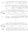
図3において、C1はカメラ1からの映像信号、C2はカメラ2からの映像信号であり、1つの□は1フィールドの映像を示す。設定手段4には、映像切換タイミング情報として60フィールドが予め設定され、切換タイミング手段3からの切換タイミング信号aは60フィールド毎にハイレベル/ローレベル(H/L)に制御される。そして、映像信号Vは、60フィールド毎に映像信号C1,C2が切り換えられる。
【0019】
以上のように構成された本実施の形態1の映像切換装置の作用を、図1〜図3を用いて説明する。
まず、カメラ1からの映像信号C1が第1映像入力手段1に入力され、第1映像出力手段2からカメラ2の外部同期入力へ出力される。そして、カメラ1とカメラ2との映像信号の同期がとられる。
【0020】
また、設定手段4において予め60フィールドに設定された映像切換タイミング情報と、第1映像入力手段1により入力された映像信号C1を基に、切換タイミング手段3は60フィールド毎にH/L制御された切換タイミング信号aを出力する。
【0021】
そして、切換手段5は、カメラ2の接続された第2映像入力手段6により入力された映像信号C2と第1映像入力手段1により入力された映像信号C1とを切換タイミング信号aにしたがい切り換える。切り換えられた映像信号Vは、60フィールド毎に映像信号C1,C2に切り換えられ、第2映像出力手段7から出力される。
【0022】
ここでは、設定手段4で映像切換タイミング情報が60フィールドに設定された場合の例を用いたが、任意のフィールド数が選定できる。さらに、フィールド単位でなく水平走査線数の選定も可能であり、フィールド内で切り換えた切換タイミング信号a’(図3)の場合、1画面内で映像信号C1,C2を切り換えることもできる(図3の映像V’)。さらに、複数の映像切換装置10を1本の映像ケーブルに接続し、対応するカメラをこれら映像切換装置10に接続することにより、上記映像Vの映像信号C1,C2を新たに接続したカメラの映像信号に切り換えることもできる。
【0023】
このように、映像切換装置10を設けることにより、同一映像用ケーブル上に接続された複数台のカメラを順次切り換える監視システムを提供することができる。さらに、少数カメラの監視システムやカメラの増設にも容易に対応できる監視システムを提供することができる。
(実施の形態2,3)
図4は、本発明の実施の形態2における映像切換装置のブロック図である。
【0024】
本実施の形態2における映像切換装置20は、外部からの映像信号Aを入力する映像入力手段26と、映像を識別するための映像に書き込むカメラ番号の書き込みタイミング情報と識別の必要な映像数(同一ケーブルに接続されるカメラの台数)を設定する設定手段24と、設定手段24によって予め設定された上記情報と映像入力手段26により入力された映像信号Aを基にカメラ番号書き込みタイミング信号a1を形成するタイミング手段23と、映像入力手段26により入力された映像信号Aにタイミング信号a1にしたがってカメラ番号を書き込むID書き込み手段261と、そのカメラ番号の書き込まれた映像信号V1を出力する映像出力手段27とを備えている。
【0025】
図5は、本発明の実施の形態3における映像切換装置30の構成図である。
本実施の形態3における映像切換装置30は、外部からの映像信号Vk-1 (kは2以上のカメラ番号である)を入力する第1映像入力手段31と、第1映像入力手段31により入力された映像信号Vk-1 を出力する第1映像出力手段32と、映像を識別するための映像に書き込まれたカメラ番号の何番目のカメラ番号を識別するかを設定する設定手段34と、第1映像入力手段31により入力された映像信号Vk-1 に書き込まれたカメラ番号を読み出すID読み出し手段311と、設定手段34によって予め設定された識別するカメラ番号kと、ID読み出し手段311にて読み出されたカメラ番号を基に切換タイミング信号bを形成する切換タイミング手段33と、外部からの映像信号Bを入力する第2映像入力手段36と、第2映像入力手段36により入力された映像信号Bと第1映像入力手段31により入力された映像信号Vk-1 とを切換タイミング信号bにより切り換える切換手段35と、その切り換えた映像信号Vk を出力する第2映像出力手段37とを備えている。
【0026】
図6は本発明の実施の形態2,3を用いたn台のカメラの接続図であり、図7は動作を示すタイミングチャートである。
図6において、カメラ1は映像切換装置20の映像入力手段26に接続され、カメラ2は映像切換装置30の第2映像入力手段36に接続される。また、同期合わせ用として第1映像出力手段32の映像信号V1が、カメラ2の外部同期入力に接続され、カメラ1とカメラ2との映像の同期がとられる。同様にして、n番目のカメラnまで映像切換装置30により同一映像ケーブル上に接続される。ここでのカメラは外部同期対応カメラとする。
【0027】
カメラ1に接続する映像切換装置20の設定手段24には、カメラ番号書き込みタイミング情報として1フィールドが予め設定され、識別の必要な映像数(カメラ台数)としてnが設定されているとする。また、カメラ2に接続する映像切換装置30の設定手段34には、認識するカメラ番号kとして2番(k=2)が設定され、カメラnに接続する映像切換装置30の設定手段34には、認識するカメラ番号kとしてn番(k=n)が設定されているとする。
【0028】
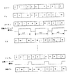
図7において、Aはカメラ1からの映像信号、Bはカメラ2からの映像信号、Nはカメラnからの映像信号であり、1つの□は1フィールドの映像を示す。
映像信号V1は、上記のように映像切換装置20の設定手段24に、カメラ番号書き込みタイミングとして1フィールドが設定され、カメラ台数としてnが設定された場合の映像信号であり、映像切換装置20の映像出力手段27から出力される。この映像信号V1はカメラ1の映像信号Aにカメラ番号が書き込まれたもので、カメラ番号1〜nが1フィールド毎に書き込まれ、これがnフィールド毎に繰り返される。映像信号Aにカメラ番号1、2〜、nの書き込まれた映像をA1、A2、・・・、Anとする。
【0029】
切換タイミング信号bは、カメラ2に接続された映像切換装置30の切換タイミング手段33から出力される切換信号であり、映像切換装置30の設定手段34に認識するカメラ番号kとして2番(k=2)が設定されていることにより、映像信号V1のカメラ番号が2番のフィールド毎にハイレベル(H)となる。ここで、切換タイミング信号は、カメラ番号の書き込まれた部分を除いた映像部分のみ切り換えるものとする。
【0030】
映像信号V2は、切換タイミング信号bのHフィールド毎に映像信号V1がカメラ2の映像信号Bに切り換えられる。
同様に、カメラ番号に相当するフィールドがそれぞれのカメラ映像に切り換えられ、切換タイミング信号nは、カメラnが接続された映像切換装置30の切換タイミング手段33から出力される切換タイミング信号であり、カメラ番号kがn番のフィールド毎にHとなる。そして、映像信号Vnは、切換タイミング信号nのHフィールド毎に映像信号Vn-1がカメラnの映像信号Nに切り換えられる。
【0031】
以上のように構成された本実施の形態2,3の映像切換装置の動作を、図4〜7を用いて説明する。
まず、カメラ1からの映像信号Aが映像切換装置20の映像入力手段26に入力され、映像切換装置20の設定手段24に予めカメラ番号書き込みタイミング情報として1フィールド、カメラ台数としてn台が設定されていることにより、タイミング手段23より1フィールド単位で1〜nまでのカメラ番号を書き込むための情報がID書き込み手段261に送られる。ID書き込み手段261は映像入力手段26により入力された映像信号Aにカメラ番号1〜nを順次書き込む。そして、この書き込まれた映像信号V1は映像出力手段27より出力される。
【0032】
よって、映像信号V1はカメラ1の映像信号Aにカメラ番号が書き込まれたもので、カメラ番号1〜nが1フィールド毎に書き込まれ、これがnフィールド毎に繰り返される。すなわち、映像信号A1、A2、・・・、Anが繰り返される。
【0033】
次に、映像信号V1は映像切換装置30の第1映像入力手段31に入力され、第1映像出力手段32は第1映像入力手段31により入力された映像信号V1をカメラ2の外部同期入力に出力される。そして、カメラ1とカメラ2の映像信号の同期がとられる。設定手段34に予め設定された、識別するカメラ番号kとしての2番と、ID読み出し手段311により読み出された、第1映像入力手段31により入力された映像信号V1に書き込まれたカメラ番号を基に、カメラ番号が2番のフィールドのみハイレベル(H)となる切換タイミング信号bが切換タイミング手段33において形成される。
【0034】
カメラ2の映像信号Bは第2映像入力手段36に入力される。そして、切換手段35は、第1映像入力手段31により入力された映像信号V1を切換タイミング信号bのHフィールド毎にカメラ2の映像信号Bに切り換える。第2映像出力手段37は、その切り換えた映像信号V2を出力する。すなわち、映像信号V2は、映像A1、B2、・・・、Anとなる。ここでは、映像信号A2のフィールドを映像信号Bに切り換えるが、映像部分のみ切り換えカメラ番号部分は切り換えないものとし、カメラ番号2の書き込まれた映像信号B、すなわち、映像B2に切り換えられるものとする。
【0035】
同様に、設定手段34により設定されたカメラ番号kに相当するフィールドがそれぞれのカメラの映像信号に切り換えられる。そして、n番目のカメラnに接続された映像切換装置30では、切換タイミング手段33から出力される切換タイミング信号nはカメラ番号kがn番のフィールド毎にHとなり、映像信号Vnは切換タイミング信号nのHフィールド毎にカメラnの映像信号Nに切り換えられる。
【0036】
ここでは、設定手段24にカメラ番号書き込みタイミングとして1フィールドが設定され、カメラ台数としてn台が設定された場合の例を用いたが、任意のフィールド数、任意のカメラ台数を選定できる。
【0037】
このように、各カメラ毎に映像切換装置20,30を設けることにより、同一映像用ケーブル上に接続されたn台のカメラを順次切り換える監視システムを提供することができる。さらに、少数カメラの監視システムやカメラの増設にも容易に対応できる監視システムを提供できる。
(実施の形態4)
図8は、本発明の実施の形態4における映像切換装置のブロック図である。
【0038】
本実施の形態4の映像切換装置40は、外部からの映像信号Vk-1 (kは2以上のカメラ番号である)を入力する第1映像入力手段41と、第1映像入力手段41により入力された映像信号Vk-1 を出力する第1映像出力手段42と、映像を識別するための映像に書き込むカメラ番号の書き込みタイミング情報と識別の必要な映像数(同一ケーブルに接続されるカメラ台数)、および映像信号に書き込まれたカメラ番号の何番目のカメラ番号を識別するかを設定する設定手段44と、第1映像入力手段41により入力された映像信号Vk-1 に書き込まれたカメラ番号を読み出すID読み出し手段411と、設定手段44によって予め設定された上記情報と、ID読み出し手段411により読み出されたカメラ番号を基に、切換タイミング信号bとカメラ番号書き込みタイミング信号cを形成する切換タイミング手段43と、外部からの映像信号Bを入力する第2映像入力手段46と、第2映像入力手段46により入力された映像信号Bに前記カメラ番号書き込みタイミング信号cに基づきカメラ番号kを書き込むID書き込み手段461と、第2映像入力手段46により入力された映像信号Bにカメラ番号が書き込まれた映像信号B2と第1映像入力手段41により入力された映像信号Vk-1とを前記切換タイミング信号bにより切り換える切換手段45と、切換手段45により切り換えられた映像信号Vk を出力する第2映像出力手段47とを備えている。 図9は本発明の実施の形態4におけるn台のカメラの接続図であり、図10は動作を示すタイミングチャートである。
【0039】
図9において、カメラ1は映像切換装置40の第2映像入力手段46に接続され、カメラ2は映像切換装置40の第2映像入力手段46に接続される。また、同期合わせ用として第1映像出力手段42がカメラ2の外部同期入力に接続されカメラ1とカメラ2との映像は同期がとられる。同様にして、n番目のカメラnまで映像切換装置40により同一映像ケーブル上に接続される。ここでのカメラは外部同期対応カメラとする。
【0040】
カメラ1に接続する映像切換装置40の設定手段44には、識別するカメラ番号kとして1番、識別の必要な映像数(カメラ台数)としてn、書き込みタイミング情報として1フィールドが設定され、またカメラ2に接続する映像切換装置40の設定手段44には、識別するカメラ番号kとして2番、カメラ台数としてn、書き込みタイミング情報として1フィールドが設定され、さらにカメラnに接続する映像切換装置40の設定手段44には、識別するカメラ番号kとしてnが設定されているとする。
【0041】
図10において、Aはカメラ1からの映像信号、Bはカメラ2からの映像信号であり、Nはカメラnからの映像信号であり、1つの□は1フィールドの映像を示す。
【0042】
映像信号V1は、映像切換装置40の設定手段44に、予めカメラ番号として1番が設定されていることによる映像であり、映像切換装置40の第2映像出力手段47から出力される。この映像信号V1はカメラ1の映像信号Aにカメラ番号1が書き込まれたものである。映像信号V1はカメラ2の第1映像入力手段41へ入力される。
【0043】
切換タイミング信号bは、カメラ2に接続された映像切換装置40の切換タイミング手段43から出力される切換信号であり、前のカメラ番号の1フィールドを残し、(n−1){=n−k(=2)+1}フィールド間ハイレベル(H)となる。そして、映像信号V2は、切換タイミング信号bのHフィールド毎にカメラ2の映像信号B2に切り換えられる。
【0044】
同様に、前のカメラ番号のフィールドを残し、残りのフィールドをそれぞれのカメラ映像に切り換える。切換タイミング信号nは、カメラnが接続された映像切換装置40の切換タイミング手段43から出力される切換信号であり、カメラ番号のn番のフィールドがハイレベル(H)となる。
【0045】
以上のように構成された本実施の形態の映像切換装置の動作を、図8〜10を用いて説明する。
まず、カメラ1からの映像信号Aが映像切換装置40の第2映像入力手段46に入力され、映像切換装置40の設定手段44に、予めカメラ番号として1番、識別の必要な映像数(カメラ台数)としてn、書き込みタイミング情報として1フィールドが設定されていることから、切換タイミング手段43より各フィールド毎にカメラ番号1を書き込むための情報がID書き込み手段461に送られる。ID書き込み手段261は第2映像入力手段46により入力された映像信号Aにカメラ番号1を書き込む。そして、この書き込まれた映像信号V1は第2映像出力手段47より出力される。すなわち、映像信号V1はカメラ1の映像信号Aにカメラ番号1が書き込まれたものである。
【0046】
次に、映像信号V1は映像切換装置40の第1映像入力手段41に入力され、第1映像出力手段42よりカメラ2の外部同期入力に出力される。そして、カメラ1とカメラ2との映像信号の同期がとられる。
【0047】
設定手段44に予め設定されたカメラ番号2番とカメラ台数nと書き込みタイミング情報1フィールドと、ID読み出し手段411により読み出された、第1映像入力手段41により入力された映像信号V1に書き込まれたカメラ番号を基に、カメラ番号が1番の1フィールドのみローレベル(L)で(nー1)フィールドがハイレベル(H)となる切換タイミング信号bを切換タイミング手段33は形成する。
【0048】
カメラ2の映像信号Bは第2映像入力手段46に入力される。切換タイミング手段43は、設定手段44に予め設定されたカメラ番号2とカメラ台数nとカメラ番号書き込みタイミング情報1フィールド、およびID読み出し手段411により読み出された、第1映像入力手段41により入力された映像信号V1に書き込まれたカメラ番号を基に、カメラ番号書き込みタイミング信号cを形成する。
【0049】
ID書き込み手段461は、第2映像入力手段46により入力された映像信号Bにタイミング信号cにしたがいカメラ番号2を書き込む。
切換手段45は、ID書き込み手段461より出力された映像信号B2と第1映像入力手段41により入力された映像信号V1とを前記切換タイミング信号bにより切り換える。第2映像出力手段47は、その切り換えた映像信号V2を出力する。
【0050】
同様に、上流の小さいカメラ番号の映像を1フィールド分残し、残りのフィールドを次のカメラ映像に切り換える。そして、n番目のカメラnに接続された映像切換装置40では、切換タイミング手段43から出力される切換タイミング信号nはカメラ番号が1〜(n−1)番までローレベル(L)で残りの1フィールドのみハイレベル(H)となり、映像Vnは切換信号nのHフィールド毎にカメラnの映像Nに切り換えられる。
【0051】
ここでは、設定手段44に、カメラ番号書き込みタイミング情報として1フィールド、カメラ台数としてnが設定された場合の例を用いたが、任意のフィールド数、任意のカメラ台数が選定できる。
【0052】
このように、各カメラ毎に映像切換装置40を設けることにより、同一映像用ケーブル上に接続されたn台のカメラを順次切り換える監視システムを提供することができる。さらに、少数カメラの監視システムやカメラの増設にも容易に対応できる監視システムを提供できる。
【0053】
さらに、第1映像入力手段41にカメラ番号が小さいカメラからの映像が入力されなかった場合は、切換タイミング信号bは常にHのままで第2映像入力手段46により入力された映像のみ第2映像出力手段47から出力するようにすることにより、映像ケーブルに何らかの障害が発生しても、その障害の発生した以降に接続された映像切換装置40の動作は保証できる。
【0054】
なお、上記実施の形態1〜4では、アナログ映像方式のカメラで構成した例で説明したが、その他のディジタル通信方式により映像を送る場合についても同様に実施可能である。
【0055】
また、上記実施の形態1〜4では、第1映像出力手段からカメラ番号が小さいカメラからの映像信号をカメラへ出力して映像出力の同期を行っているが、第1映像出力手段の代わりに、第1映像入力手段により入力された映像信号を基準にして同期信号を形成する同期出力手段を設け、この同期出力手段から第1映像出力手段からの映像信号の代わりに同期信号を出力するようにしてもよい。
【0056】
またここでは、外部同期対応カメラを例に挙げたが、外部同期対応カメラ以外の場合も映像の切換部の映像乱れを除けば、ほぼ同様の効果をあげることができる。この場合、同期出力手段は不要となる。
【0057】
また、実施の形態1〜4で示した映像に書き込むカメラ番号を従来のスイッチャーなどに使用しているカメラ番号と同じにすることにより、従来監視システムとの互換性を保つこともできる。
【0058】
【発明の効果】
以上のように本発明によれば、各カメラ毎に映像切換装置を設けることにより、同一映像用ケーブル上に接続された複数台のカメラを順次切り換える監視システムを提供することができる。さらに、少数カメラの監視システムやカメラの増設にも容易に対応できる監視システムを提供するという有利な効果が得られる。
【図面の簡単な説明】
【図1】本発明の実施の形態1における映像切換装置のブロック図である。
【図2】本発明の実施の形態1における映像切換装置の接続図である。
【図3】図1、図2の映像および切換信号のタイミングを示す特性図である。
【図4】本発明の実施の形態2における映像切換装置のブロック図である。
【図5】本発明の実施の形態3における映像切換装置のブロック図である。
【図6】本発明の実施の形態2,3における映像切換装置の接続図である。
【図7】図4〜図7の映像および切換信号のタイミングを示す特性図である。
【図8】本発明の実施の形態4における映像切換装置のブロック図である。
【図9】本発明の実施の形態4における映像切換装置の接続図である。
【図10】図8、図9の映像および切換信号のタイミングを示す特性図である。
【符号の説明】
1 第1映像入力手段
2 第1映像出力手段
3 切換タイミング手段
4 設定手段
5 切換手段
6 第2映像入力手段
7 第2映像出力手段
10,20,30,40 映像切換装置
23 切換タイミング手段
24 設定手段
26 映像入力手段
261 ID書き込み手段
27 映像出力手段
31 第1映像入力手段
311 ID読み出し手段
32 第1映像出力手段
33 切換タイミング手段
34 設定手段
35 切換手段
36 第2映像入力手段
37 第2映像出力手段
41 第1の映像入力手段
411 ID読み出し手段
42 第1映像出力手段
43 切換タイミング手段
44 設定手段
45 切換手段
46 第2映像入力手段
461 ID書き込み手段
47 第2映像出力手段[0001]
BACKGROUND OF THE INVENTION
The present invention relates to a video switching device used in a monitoring system that sequentially switches a plurality of camera images and records them in a video recording device, and more particularly to a video switching used when a plurality of cameras are connected to one video cable. It relates to the device.
[0002]
[Prior art]
Conventionally, in a monitoring system in which video from multiple cameras is connected to a video switching device, the video output of the camera is sequentially switched by the video switching device, and recorded in the video recording device, the video cables for the number of cameras are switched. Connected to the device. Further, when synchronizing the cameras, the same number of cables as the number of cameras that transmit signals for synchronizing are connected.
[0003]
When multiple cameras are connected on the same video cable, a controller for controlling the video timing of each camera is connected to each camera by a control cable for sending the control signal, and each camera is controlled by the controller. The video output is turned on / off.
[0004]
[Problems to be solved by the invention]
However, in the conventional monitoring system for connecting video cables from the respective cameras to the video switching device, video cables as many as the number of cameras are required, and when synchronizing the cameras, the cameras to be synchronized are synchronized. There was a problem that the number of cables required was also required. Also, most conventional video switching devices have 8 or 16 camera inputs, and there is a problem that it is difficult to cope with a monitoring system for a small number of cameras and the addition of cameras.
[0005]
In addition, in a monitoring system in which a plurality of cameras are connected on the same video cable, a controller for controlling the video timing of each camera and a control cable for sending the control signal are required, and each camera is controlled by the controller. Accordingly, there is also a problem that a control function for turning on / off the video output is necessary.
[0006]
In the video switching device used in such a monitoring system, the present invention can sequentially switch a plurality of cameras on the same video cable, and can be easily added to a monitoring system for a small number of cameras and cameras. The purpose is to be able to respond.
[0007]
[Means for Solving the Problems]
In the video switching device of the present invention, first video input means for inputting an external video signal, first video output means for outputting the video signal input by the first video input means, and video switching timing information A switching timing means for forming a switching timing signal based on the video switching timing information preset by the setting means and the video signal input by the first video input means, and an external video A second video input means for inputting a signal, a switching means for switching the video signal input by the second video input means and the video signal input by the first video input means in accordance with the switching timing signal, and the switching And a second video output means for outputting the video signal.
[0008]
According to the present invention, it is possible to sequentially switch a plurality of cameras on the same video cable, and to obtain a video switching device that can easily cope with a monitoring system for a small number of cameras and the addition of cameras.
[0009]
DETAILED DESCRIPTION OF THE INVENTION
According to the first aspect of the present invention, there is provided a first video input means for inputting a video signal from the outside, a first video output means for outputting the video signal input by the first video input means, and a video Setting means for setting switching timing information; switching timing means for forming a switching timing signal based on video switching timing information preset by the setting means and a video signal input by the first video input means; Second video input means for inputting a video signal from the video signal; switching means for switching between the video signal input by the second video input means and the video signal input by the first video input means in accordance with the switching timing signal; And a second video output means for outputting the switched video signal,
The first video input means inputs an external video signal, the inputted video signal is output from the first video output means, and the switching timing means includes the video switching timing information preset in the setting means and the first video switching timing information. A switching timing signal is formed based on the video signal input by the one video input means, and the switching means inputs the video signal input by the second video input means and the first video input means in accordance with the switching timing signal. The switched video signal is switched, and the switched video is output from the second video output means.
[0010]
According to a second aspect of the present invention, there is provided a video input means for inputting a video signal from the outside, a setting means for setting the write timing information of the camera number to be written to the video to identify the video and the number of videos to be identified. Timing means for forming a camera number write timing signal based on information preset by the setting means and the video signal input by the video input means; and the timing signal to the video signal input by the video input means According to the above, the ID writing means for sequentially writing the camera number up to the number of the video, and the video output means for outputting the video signal in which the camera number is written,
The video input means inputs an external video signal, and the timing means sets the camera number write timing based on the camera number write timing information preset in the setting means, the number of cameras, and the video signal input by the video input means. The signal is formed, the ID writing means writes the camera number in the video signal input by the video input means in accordance with the camera number writing timing signal, and the video output means outputs the video in which the camera number is written. Have
[0011]
According to a third aspect of the present invention, the first video input means for inputting the video signal from the outside, the first video output means for outputting the video signal input by the first video input means, and the video are identified. Setting means for setting which camera number of the camera number written in the video signal is identified, and ID reading means for reading out the camera number written in the video signal input by the first video input means A switching timing means for forming a switching timing signal based on the camera number preset by the setting means, the camera number read by the ID reading means, and a second video for inputting an external video signal An input means; a video signal input by the second video input means; and a video signal input by the first video input means. And switching means for more switching, which was characterized by a second video output means for outputting the switched video signal,
The first video input means inputs an external video signal, the first video output means outputs the video signal input by the first video input means, and the camera number recognized in advance by the setting means, Based on the camera number written in the video signal input by the first video input means read by the ID reading means, the switching timing means forms a switching timing signal, and the switching means uses the switching timing signal. The video signal input by the second video input means and the video signal input by the first video input means are switched, and the second video output means has an effect of outputting the switched video signal.
[0012]
According to a fourth aspect of the present invention, when a plurality of cameras are connected on the same video cable, the video switching device according to the second aspect is connected to the first camera, and the third and subsequent cameras are described in the third aspect. It is characterized by connecting the video switching device of
The video signals from the
[0013]
According to a fifth aspect of the present invention, the first video input means for inputting the video signal from the outside, the first video output means for outputting the video signal input by the first video input means, and the video are identified. Setting means for setting the write timing information of the camera number to be written to the video signal and the number of videos that need to be identified, and the camera number of the camera number written to the video signal, and the first video ID reading means for reading the camera number written in the video signal input by the input means, information preset by the setting means, and a switching timing signal based on the camera number read by the ID reading means Switching timing means for forming a camera number writing timing signal, second video input means for inputting an external video signal, and the second ID writing means for writing a camera number to the video signal input by the image input means based on the camera number writing timing signal; a video signal in which a camera number is written in the video signal input by the second video input means; A switching means for switching the video signal input by the first video input means by the switching timing signal, and a second video output means for outputting the video signal switched by the switching means. Yes,
The first video input means inputs an external video signal, the first video output means outputs the video signal input by the first video input means, and a camera number writing timing preset by the setting means. Based on the camera number recognized as the number of videos and the camera number written in the video signal input by the first video input means read by the ID readout means, the switching timing means forms a switching timing signal, The second video input means inputs an external video signal, and the switching timing means inputs the camera number, camera number writing timing information, the number of videos, and the second video input means preset in the setting means. The camera number writing timing signal is formed based on the received video signal, and the ID writing means is input by the video input means. The camera number is written to the video signal in accordance with the camera number write timing signal, and the switching means switches between the video signal output from the ID writing means and the video signal input from the first video input means by the switching timing signal, The second video output means has an effect of outputting the switched video signal.
[0014]
The invention according to
The synchronization signal has the effect that the synchronization of each video signal can be obtained.
[0015]
Hereinafter, embodiments of the present invention will be described with reference to the drawings.
(Embodiment 1)
FIG. 1 is a block diagram of a video switching device according to
[0016]
The
[0017]
FIG. 2 is a connection diagram of two cameras in
In FIG. 2, the
[0018]
In FIG. 3, C1 is a video signal from the
[0019]
The operation of the video switching device of the first embodiment configured as described above will be described with reference to FIGS.
First, the video signal C1 from the
[0020]
Further, the switching timing means 3 is H / L controlled every 60 fields based on the video switching timing information previously set in 60 fields in the setting means 4 and the video signal C1 input by the first video input means 1. The switching timing signal a is output.
[0021]
The switching means 5 switches the video signal C2 input by the second video input means 6 connected to the
[0022]
Here, an example in which the video switching timing information is set to 60 fields by the setting means 4 is used, but an arbitrary number of fields can be selected. Further, it is possible to select the number of horizontal scanning lines instead of the field unit. In the case of the switching timing signal a ′ (FIG. 3) switched within the field, the video signals C1 and C2 can be switched within one screen (FIG. 3 video V ′). Furthermore, by connecting a plurality of
[0023]
Thus, by providing the
(
FIG. 4 is a block diagram of a video switching device according to
[0024]
The
[0025]
FIG. 5 is a configuration diagram of the
The
[0026]
FIG. 6 is a connection diagram of n cameras using the second and third embodiments of the present invention, and FIG. 7 is a timing chart showing the operation.
In FIG. 6, the
[0027]
In the setting means 24 of the
[0028]
In FIG. 7, A is a video signal from the
The video signal V1 is a video signal when one field is set as the camera number writing timing and n is set as the number of cameras in the setting means 24 of the
[0029]
The switching timing signal b is a switching signal output from the switching timing means 33 of the
[0030]
In the video signal V2, the video signal V1 is switched to the video signal B of the
Similarly, the field corresponding to the camera number is switched to each camera video, and the switching timing signal n is a switching timing signal output from the switching timing means 33 of the
[0031]
The operation of the video switching apparatus according to the second and third embodiments configured as described above will be described with reference to FIGS.
First, the video signal A from the
[0032]
Therefore, the video signal V1 is obtained by writing the camera number to the video signal A of the
[0033]
Next, the video signal V1 is input to the first video input means 31 of the
[0034]
The video signal B from the
[0035]
Similarly, the field corresponding to the camera number k set by the setting means 34 is switched to the video signal of each camera. In the
[0036]
Here, an example in which one field is set as the camera number writing timing in the setting means 24 and n cameras are set is used, but any number of fields and any number of cameras can be selected.
[0037]
Thus, by providing the
(Embodiment 4)
FIG. 8 is a block diagram of a video switching device according to
[0038]
The
[0039]
In FIG. 9, the
[0040]
In the setting means 44 of the
[0041]
In FIG. 10, A is a video signal from the
[0042]
The video signal V <b> 1 is an image obtained by setting the
[0043]
The switching timing signal b is a switching signal output from the switching timing means 43 of the
[0044]
Similarly, the field of the previous camera number is left and the remaining fields are switched to the respective camera images. The switching timing signal n is a switching signal output from the switching timing means 43 of the
[0045]
The operation of the video switching device of the present embodiment configured as described above will be described with reference to FIGS.
First, the video signal A from the
[0046]
Next, the video signal V <b> 1 is input to the first video input means 41 of the
[0047]
The
[0048]
The video signal B from the
[0049]
The ID writing means 461 writes the
The switching unit 45 switches between the video signal B2 output from the
[0050]
Similarly, the video of the small camera number upstream is left for one field, and the remaining fields are switched to the next camera video. In the
[0051]
Here, an example in which one field is set as the camera number writing timing information and n is set as the number of cameras in the setting means 44 is used, but any number of fields and any number of cameras can be selected.
[0052]
As described above, by providing the
[0053]
Further, when the video from the camera with the smaller camera number is not input to the first video input means 41, the switching timing signal b always remains H and only the video input by the second video input means 46 is the second video. By outputting from the output means 47, even if a failure occurs in the video cable, the operation of the
[0054]
In the first to fourth embodiments, an example in which an analog video camera is used has been described. However, the present invention can be similarly applied to a case in which video is transmitted by another digital communication method.
[0055]
In the first to fourth embodiments, the video signal from the camera with the smaller camera number is output from the first video output means to the camera to synchronize the video output, but instead of the first video output means. A synchronization output means for forming a synchronization signal based on the video signal input by the first video input means, and the synchronization output means outputs a synchronization signal instead of the video signal from the first video output means. It may be.
[0056]
Here, the external synchronization compatible camera has been described as an example. However, in the case of a camera other than the external synchronization compatible camera, substantially the same effect can be obtained except for the video disturbance of the video switching unit. In this case, the synchronous output means becomes unnecessary.
[0057]
Further, by making the camera number written in the video shown in the first to fourth embodiments the same as the camera number used in a conventional switcher or the like, compatibility with a conventional monitoring system can be maintained.
[0058]
【The invention's effect】
As described above, according to the present invention, it is possible to provide a monitoring system that sequentially switches a plurality of cameras connected on the same video cable by providing a video switching device for each camera. Furthermore, the advantageous effect of providing a monitoring system that can easily cope with the monitoring system of a small number of cameras and the addition of cameras can be obtained.
[Brief description of the drawings]
FIG. 1 is a block diagram of a video switching device according to
FIG. 2 is a connection diagram of a video switching device according to
FIG. 3 is a characteristic diagram showing the timing of the video and switching signal in FIGS. 1 and 2;
FIG. 4 is a block diagram of a video switching device according to
FIG. 5 is a block diagram of a video switching device according to
FIG. 6 is a connection diagram of the video switching device according to the second and third embodiments of the present invention.
FIG. 7 is a characteristic diagram showing the timing of the video and switching signal in FIGS.
FIG. 8 is a block diagram of a video switching device according to
FIG. 9 is a connection diagram of a video switching device according to
10 is a characteristic diagram showing the timing of the video and switching signal in FIGS. 8 and 9. FIG.
[Explanation of symbols]
1 First video input means
2 First video output means
3 Switching timing means
4 Setting means
5 Switching means
6 Second video input means
7 Second video output means
10, 20, 30, 40 Video switching device
23 Switching timing means
24 Setting means
26 Video input means
261 ID writing means
27 Video output means
31 First video input means
311 ID reading means
32 First video output means
33 Switching timing means
34 Setting means
35 switching means
36 Second video input means
37 Second video output means
41 First video input means
411 ID reading means
42 First video output means
43 Switching timing means
44 Setting means
45 switching means
46 Second video input means
461 ID writing means
47 Second video output means
Claims (6)
前記第1映像入力手段により入力された映像信号を出力する第1映像出力手段と、
映像切換タイミング情報を設定する設定手段と、
前記設定手段によって予め設定された映像切換タイミング情報と前記第1映像入力手段により入力された映像信号を基に切換タイミング信号を形成する切換タイミング手段と、
外部からの映像信号を入力する第2映像入力手段と、
前記第2映像入力手段により入力された映像信号と第1映像入力手段により入力された映像信号とを前記切換タイミング信号にしたがって切り換える切換手段と、
その切り換えた映像信号を出力する第2の映像出力手段と
を備えたことを特徴とする映像切換装置。First video input means for inputting an external video signal;
First video output means for outputting a video signal input by the first video input means;
Setting means for setting video switching timing information;
Switching timing means for forming a switching timing signal based on the video switching timing information preset by the setting means and the video signal input by the first video input means;
Second video input means for inputting an external video signal;
Switching means for switching between the video signal input by the second video input means and the video signal input by the first video input means in accordance with the switching timing signal;
And a second video output means for outputting the switched video signal.
映像を識別するために映像に書き込むカメラ番号の書き込みタイミング情報と識別の必要な映像数を設定する設定手段と、
前記設定手段によって予め設定された情報と前記映像入力手段により入力された映像信号を基にカメラ番号書き込みタイミング信号を形成するタイミング手段と、
前記映像入力手段により入力された映像信号に前記タイミング信号にしたがって順に前記映像数までのカメラ番号を書き込むID書き込み手段と、
前記そのカメラ番号が書き込まれた映像信号を出力する映像出力手段と
を備えたことを特徴とする映像切換装置。Video input means for inputting an external video signal;
Setting means for setting the writing timing information of the camera number to be written to the video to identify the video and the number of videos required for identification;
Timing means for forming a camera number writing timing signal based on the information preset by the setting means and the video signal input by the video input means;
ID writing means for sequentially writing camera numbers up to the number of videos according to the timing signal to the video signal input by the video input means;
And a video output means for outputting a video signal in which the camera number is written.
前記第1映像入力手段により入力された映像信号を出力する第1映像出力手段と、
映像を識別するために映像信号に書き込まれたカメラ番号の何番目のカメラ番号を識別するかを設定する設定手段と、
前記第1映像入力手段により入力された映像信号に書き込まれたカメラ番号を読み出すID読み出し手段と、
前記設定手段によって予め設定されたカメラ番号と、前記ID読み出し手段により読み出されたカメラ番号を基に切換タイミング信号を形成する切換タイミング手段と、
外部からの映像信号を入力する第2映像入力手段と、
前記第2映像入力手段により入力された映像信号と前記第1映像入力手段により入力された映像信号とを前記切換タイミング信号により切り換える切換手段と、
その切り換えた映像信号を出力する第2映像出力手段と
を備えたことを特徴とする映像切換装置。First video input means for inputting an external video signal;
First video output means for outputting a video signal input by the first video input means;
Setting means for setting what number of the camera number written in the video signal to identify the video; and
ID reading means for reading the camera number written in the video signal input by the first video input means;
Switching timing means for forming a switching timing signal based on the camera number preset by the setting means and the camera number read by the ID reading means;
Second video input means for inputting an external video signal;
Switching means for switching between the video signal input by the second video input means and the video signal input by the first video input means by the switching timing signal;
And a second video output means for outputting the switched video signal.
前記第1映像入力手段により入力された映像信号を出力する第1映像出力手段と、
映像を識別するために映像信号に書き込むカメラ番号の書き込みタイミング情報と識別の必要な映像数、および映像信号に書き込まれたカメラ番号の何番目のカメラ番号を識別するかを設定する設定手段と、
前記第1映像入力手段により入力された映像信号に書き込まれたカメラ番号を読み出すID読み出し手段と、
前記設定手段によって予め設定された情報と、前記ID読み出し手段により読み出されたカメラ番号を基に切換タイミング信号とカメラ番号書き込みタイミング信号を形成する切換タイミング手段と、
外部からの映像信号を入力する第2映像入力手段と、
前記第2映像入力手段により入力された映像信号に前記カメラ番号書き込みタイミング信号に基づきカメラ番号を書き込むID書き込み手段と、
前記第2映像入力手段により入力された映像信号にカメラ番号が書き込まれた映像信号と前記第1映像入力手段により入力された映像信号とを前記切換タイミング信号により切り換える切換手段と、
前記切換手段により切り換えた映像信号を出力する第2映像出力手段と
を備えたことを特徴とする映像切換装置。First video input means for inputting an external video signal;
First video output means for outputting a video signal input by the first video input means;
Setting means for setting the write timing information of the camera number to be written to the video signal in order to identify the video, the number of videos required for identification, and the camera number of the camera number written to the video signal,
ID reading means for reading the camera number written in the video signal input by the first video input means;
Switching timing means for forming a switching timing signal and a camera number writing timing signal based on information preset by the setting means and the camera number read by the ID reading means;
Second video input means for inputting an external video signal;
ID writing means for writing a camera number to the video signal input by the second video input means based on the camera number writing timing signal;
Switching means for switching between a video signal in which a camera number is written in a video signal input by the second video input means and a video signal input by the first video input means by the switching timing signal;
And a second video output means for outputting the video signal switched by the switching means.
Priority Applications (1)
| Application Number | Priority Date | Filing Date | Title |
|---|---|---|---|
| JP30227897A JP3688105B2 (en) | 1997-11-05 | 1997-11-05 | Video switching device and video switching equipment using the video switching device |
Applications Claiming Priority (1)
| Application Number | Priority Date | Filing Date | Title |
|---|---|---|---|
| JP30227897A JP3688105B2 (en) | 1997-11-05 | 1997-11-05 | Video switching device and video switching equipment using the video switching device |
Publications (2)
| Publication Number | Publication Date |
|---|---|
| JPH11146386A JPH11146386A (en) | 1999-05-28 |
| JP3688105B2 true JP3688105B2 (en) | 2005-08-24 |
Family
ID=17907089
Family Applications (1)
| Application Number | Title | Priority Date | Filing Date |
|---|---|---|---|
| JP30227897A Expired - Fee Related JP3688105B2 (en) | 1997-11-05 | 1997-11-05 | Video switching device and video switching equipment using the video switching device |
Country Status (1)
| Country | Link |
|---|---|
| JP (1) | JP3688105B2 (en) |
Families Citing this family (1)
| Publication number | Priority date | Publication date | Assignee | Title |
|---|---|---|---|---|
| DE102005022886A1 (en) * | 2005-05-18 | 2006-11-23 | Bayerische Motoren Werke Ag | Trouble-free image stream displaying method for motor vehicle, involves signaling end of image forming phase, starting switching unit immediately after reception of signal and ending switching phase, where end times of phases are equal |
-
1997
- 1997-11-05 JP JP30227897A patent/JP3688105B2/en not_active Expired - Fee Related
Also Published As
| Publication number | Publication date |
|---|---|
| JPH11146386A (en) | 1999-05-28 |
Similar Documents
| Publication | Publication Date | Title |
|---|---|---|
| CN101690216A (en) | Transmission device, information transmission method, reception device, and information processing method | |
| JPS61117989A (en) | Television receiver | |
| JP3688105B2 (en) | Video switching device and video switching equipment using the video switching device | |
| EP0487182A2 (en) | Video signal recording apparatus | |
| JP3050149B2 (en) | Video recording and playback device | |
| JP3444091B2 (en) | Video data display method | |
| JP2005062997A (en) | Data transfer controller, disk recorder, and data transfer control method | |
| US5285262A (en) | High resolution video acquisition system | |
| JPH0573312B2 (en) | ||
| KR100571764B1 (en) | Apparatus and methods for data security of a data processing system | |
| KR200309017Y1 (en) | Matrix Switcher for Digital Video Recorder | |
| JPH0816943A (en) | Monitor camera | |
| JP2000125284A (en) | Monitor camera system | |
| JP2580364B2 (en) | Image recording and playback device | |
| JPH05173530A (en) | Multiinput video signal display device | |
| WO2000060867A1 (en) | Digital video lan system | |
| JPH06197344A (en) | Video display system | |
| JPH06253213A (en) | Video signal switching device | |
| JPH06153015A (en) | Remote controller for video equipment | |
| JPH05176229A (en) | Multi-input video signal display device | |
| JP2000165849A (en) | Supervisory camera system | |
| JPH05103278A (en) | Picture in picture system | |
| JP2004320499A (en) | Image signal input/output device, display device, and recorder | |
| JPH0213191A (en) | Standard system conversion method | |
| EP1001424A2 (en) | Digital information editing system |
Legal Events
| Date | Code | Title | Description |
|---|---|---|---|
| A977 | Report on retrieval |
Free format text: JAPANESE INTERMEDIATE CODE: A971007 Effective date: 20050426 |
|
| TRDD | Decision of grant or rejection written | ||
| A01 | Written decision to grant a patent or to grant a registration (utility model) |
Free format text: JAPANESE INTERMEDIATE CODE: A01 Effective date: 20050510 |
|
| A61 | First payment of annual fees (during grant procedure) |
Free format text: JAPANESE INTERMEDIATE CODE: A61 Effective date: 20050607 |
|
| FPAY | Renewal fee payment (event date is renewal date of database) |
Free format text: PAYMENT UNTIL: 20080617 Year of fee payment: 3 |
|
| FPAY | Renewal fee payment (event date is renewal date of database) |
Free format text: PAYMENT UNTIL: 20090617 Year of fee payment: 4 |
|
| FPAY | Renewal fee payment (event date is renewal date of database) |
Free format text: PAYMENT UNTIL: 20100617 Year of fee payment: 5 |
|
| LAPS | Cancellation because of no payment of annual fees |