JP3688024B2 - Metal gasket and manufacturing method thereof - Google Patents
Metal gasket and manufacturing method thereof Download PDFInfo
- Publication number
- JP3688024B2 JP3688024B2 JP24553495A JP24553495A JP3688024B2 JP 3688024 B2 JP3688024 B2 JP 3688024B2 JP 24553495 A JP24553495 A JP 24553495A JP 24553495 A JP24553495 A JP 24553495A JP 3688024 B2 JP3688024 B2 JP 3688024B2
- Authority
- JP
- Japan
- Prior art keywords
- material layer
- sealing material
- bead
- thickness
- metal plate
- Prior art date
- Legal status (The legal status is an assumption and is not a legal conclusion. Google has not performed a legal analysis and makes no representation as to the accuracy of the status listed.)
- Expired - Fee Related
Links
Images


Description
【0001】
【発明の属する技術分野】
本発明はエンジンのシリンダヘッド用ガスケット等として用いる金属ガスケットに関するものである。
【0002】
【従来の技術】
シリンダボアや冷却水、オイル通路穴等の流体流通穴の周りに、該穴を囲繞しシールするビードを備えた金属板ガスケットにおいてはシリンダヘッドやシリンダブロック等のシールすべき接合面に接するガスケットの表面に、また、ガスケットが複数の金属板を積層してなるときは積層された金属板の対向面にも、接合面や金属板の表面の粗さ、歪み、傷等を補償するいわゆるミクロシールのために、ゴム、プラスチックよりなるシール性の被覆いわゆるシール材層を被覆している。
【0003】
このシール材層は均一な厚さに被覆されており、例えばシリンダヘッドに接する側とシリンダブロックに接する側とにおいてその厚さを異ならせるという提案はあるが、ガスケットもしくはその構成金属板の同一の表面内においては均一な厚さに被覆されており、シール材層の厚さの不均一はシール性能を損うものと考えられてきた。
【0004】
従って、金属ガスケットの製作においても、シール材層を均一な厚さに被覆できるように、金属板にビードや折返し等の傾斜や段差を生じる加工を施す前の平坦な金属板にシール材層を被覆し、シール材層の被覆後にビードや折返し等の傾斜や段差を生じる加工を施していた。
【0005】
【発明が解決しようとする課題】
均一な厚さのシール材層を有する従来の金属ガスケットにおいては、ガスケットを接合面間に締付けたときに形成される面圧が高いシール線は、専ら、ビード、折返し、グロメット等の金属加工によって金属板表面に形成された凸部やバネ弾性部によって形成され、シール材層は前記のいわゆるミクロシール機能を果たすだけであってシール材層は面圧が高いシール線の形成には全く寄与していない。
【0006】
本発明はこの点に着目したもので、金属ガスケットをシールすべき接合面間に装着し、締付けたときに、シール材層がいわゆるミクロシールの機能を果たすだけでなく、面圧が高いシール線をも形成し得るようになし、シールすべき開口の周りのシール線をより多重化し、シール性能を向上させることを目的とするものである。また、本発明はかかる金属ガスケットを有利に製造し得る製造方法を提案するものである。
【0007】
【課題を解決するための手段】
上記目的を達成するために、本発明の請求項1記載の発明は、弾性を有する金属板に流体流通穴と該流体流通穴を囲繞しシールする突状ビードとを設け、該金属板の両面にゴム、プラスチック等からなるシール材層を被覆した金属ガスケットにおいて、ビード基部の反対側表面及びビード頂部の裏面における上記シール材層の厚さを該金属板の平坦部におけるシール材層の厚さの2倍以上好ましくは3倍以上としたことを特徴とするものである。
【0008】
上記の請求項1記載の発明の金属ガスケットを有利に製造し得る製造方法を提案する本発明の請求項4記載の発明は、弾性を有する金属板の平板に流体流通穴を囲繞する突状ビードを形成したのち、該金属板表面を水平に保った状態でその上面に粘度が10,000乃至30,000CPのゴム、プラスチック塗料を塗装してシール材層を形成し、次いで該金属板を裏返し、裏返した上面に上記ゴム、プラスチック塗料を塗装してシール材層を形成することにより、ビード基部の反対側表面及びビード頂部の裏面に該金属板の平坦部におけるシール材層の厚さの2倍以上の厚さのシール材層を形成することを特徴とするものである。
【0009】
ここで、シール材層の厚さを厚くする部位をビード基部の反対側表面及びビード頂部の裏面とするのは次の理由による。すなわち、シール材層の厚さが均一な従来のガスケットのビード基部においては、締付けたとき、ビード基部が当接する接合面すなわちビード突出側と反対側の表面に接する接合面だけに面圧が高いシール線が形成され、ビード突出側の表面に接する接合面にはシール線が形成されない。また、ビード頂部においては、締付けたとき、ビード頂部が当接する接合面すなわちビード突出側の表面に接する接合面だけにシール線が形成され、反対側の接合面にはシール線が形成されない。従って、本発明においては従来のビードではシール線が形成されない上記部位にシール材層によるシール線を形成し、シール線の多重化を図るべく、上記部位のシール材層の厚さを厚くする。
【0010】
そして、上記部位のシール材層の厚さを平坦部におけるシール材層の厚さ、すなわち標準厚さの2倍以上の厚さとするのは、該部位の裏面側におけるシール材層の厚さが標準厚さよりも薄い場合においても、表裏全体のシール材層の厚さがシール線を形成するに充分なシール材層厚さを確保するためであり、好ましくは、上記部位のシール材層の厚さは金属板の平坦部のシール材層厚さの3倍以上とする。また、シール材層の局部的厚さ効果によって接合面に効果的にシール線を形成するためには、シール材層は接合面や金属板の表面の粗さ、歪み、傷等を補償するミクロシールの機能を果たすに充分な柔軟性を有しながら、或る程度の硬さをもつことが望ましく、かかる点から本発明の請求項3記載の発明の通り、シール材層はJISK6301に規定の硬度で75乃至90の硬さを有するのが好ましい。
【0011】
本発明の請求項4記載の発明の製造法によれば、弾性を有する金属板にビード及び必要に応じて折返し部、グロメット等を形成したのち、該金属板表面を水平に保った状態でその上面に、またそれを裏返した上面に粘度が10,000乃至30,000CPのゴム、プラスチック塗料を塗布するので、傾斜の下部になる、ビード基部の反対側表面及びビード頂部の裏面に該塗料が自然流下し、これらの部位のシール材層の厚さが厚くなり、平坦部のシール材層の厚さの2倍以上の厚さとすることができる。
【0012】
このとき、ゴム、プラスチック塗料の1回の塗装によるシール材層形成の厚さが10μm未満であると、塗料塗布層の厚さが薄いために表面張力の影響で塗料の自然流下量が減少するので、塗料の1回の塗装によるシール材層形成の厚さは10μm以上であることが好ましい。また、塗装した塗料の乾燥が早過ぎても塗料の自然流下量が減少するので、ゴム、プラスチック塗料の溶剤には例えば酢酸イソアミル、イソブチルケトン等の沸点が130℃以上の溶剤を用いるのが好ましい。
【0013】
【発明の実施の形態】
本発明の請求項1記載の発明の実施の形態を図面に基づき以下に説明する。図1は本発明を適用したシリンダヘッドガスケットの平面図であり、該ガスケットは単板の金属板1からなり、シリンダボア2、冷却水通路穴やオイル通路穴等の液体通路穴3及び締結ボルト(図示せず)を挿通するボルト穴4を備えている。各シリンダボア2の周りには、シリンダボア2を囲繞しシールする山形ビード5を備え、また、液体通路穴3の周りには該穴3を囲繞しシールするステップビード6を備えている。図1ではビード5及び6はともにその頂部を点線で示している。
【0014】
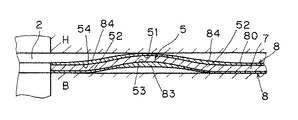
図2及び図3は図1のA−A線による拡大断面図で、シリンダヘッドH及びシリンダブロックBとの間に装着された状態を示している。ただし、図2はボルト(図示せず)が未締結でガスケットを締付けていない状態を示し、図3はボルトを締結しガスケットを締付けた状態を示し、シリンダヘッド及びブロックの接合面に発生する面圧をも表示している。
【0015】
図2に明瞭に示されているように、本発明による金属ガスケットは金属板1の表裏両面に加硫ゴム等からなるシール材層8を備えているが、その厚さがビード部分においては部位によって異なり、山形ビード5のビード基部52の反対側表面54におけるシール材層84及びビード頂部51の裏面53におけるシール材層83の厚さは他部位のシール材層の厚さよりも厚く、金属板1の平坦部7のシール材層80の厚さの2倍以上、好ましくは3倍以上の厚さに形成されている。
【0016】
なお、ビード頂部51のシール材層及びビード基部52のシール材層はその厚さが他の部位のシール材層厚さより薄くなっているが、これは図示の金属ガスケットが前記した本発明の請求項4記載の発明の製造方法により製作されたことによるもので、詳細は後述する。他の部位よりも厚さが薄い上記部位のシール材層においても前記のミクロシールの機能を果たすに充分な厚さは保持している。
【0017】
上記の金属ガスケットを図3に示すようにシリンダヘッドH及びシリンダブロックBとの間で締付け、押圧したとき、シリンダヘッドHとシリンダブロックBの接合面には図示の通りの高面圧のシール線が発生する。シール材層の厚さが均一な従来の金属ガスケットをシリンダヘッドHとシリンダブロックBとの間で締付け、押圧したときに発生する高面圧のシール線を表示する図4と較べると、従来のガスケットにおいてはシール線が形成されないビード頂部51の裏面53及びビード基部52の反対側表面54において、本発明によるガスケットでは、上記部位のシール材層の局部的な厚さ増大効果により高面圧のシール線が形成され、シール線がそれだけ多重化され、シール性能が向上することが理解される。
【0018】
次に、図5は、図1のC−C線による拡大断面図であり、シリンダヘッドH及びシリンダブロックBとの間に装着した状態(ただし、締付けていない状態)を示している。図に明瞭に示されている通り、金属板1の両面に被覆したシール材層8の厚さは液体通路穴3の周りのステップビード6の部分においても、その部位により厚さを異にしている。すなわち、ビード基部62の反対側表面64におけるシール材層86及びビード頂部61の裏面63におけるシール材層87の厚さは他部位のシール材層の厚さよりも厚く、金属板1の平坦部7のシール材層80の厚さの2倍以上、好ましくは3倍以上の厚さに形成されている。なお、ビード頂部61のシール材層及びビード基部62のシール材層の厚さが他部位のシール材層厚さより薄いが、前記のミクロシール機能を果たすに充分な厚さを保持していることは前記の山形ビードの場合と同様である。
【0019】
上記ガスケットをシリンダヘッドHとシリンダブロックBとの接合面の間で締付け、押圧したときにシリンダヘッドH及びブロックBの接合面に発生し、液体通路穴3を囲繞する高面圧のシール線を図6に示している。図7は均一な厚さのシール材層を有する従来の金属ガスケットをシリンダヘッドHとシリンダブロックBとで締付け、押圧したときにシリンダヘッドH及びブロックBに発生する高面圧のシール線を示している。図6及び図7を比較することにより、従来のガスケットにおいてはシール線が形成されないビード頂部61の裏面側及びビード突出側表面のビード基部52において、本発明によるガスケットでは、該部位のシール材層の局部的な厚さ増大に基づき高面圧のシール線が形成され、シール線がそれだけ多重化し、シール性能を向上していることがわかる。
【0020】
以上、本発明の請求項1記載の発明を単板構成のシリンダヘッドガスケットについて説明したが、本発明の金属ガスケットは単板構成に限られるものではなく、例えば上記説明した金属板1の片面もしくは両面に副板もしくは表面板を積層してもよく、或は上記説明した金属板1を中間板の両側に積層してもよく、公知の積層金属ガスケットの積層構成技術に従って適宜に積層構成することができる。また、適用対象も、上記説明したシリンダヘッドガスケットに限られるものではない。更に、上記説明においては山形ビードとステップビードについて説明したが、これに限られる訳ではなく、台形ビードを備える金属ガスケットにも同様に適用できる。そしてシール材層8は金属板1の表面全面に被覆することは必ずしも必要ではなく、ビード部分のみに好ましくはビードの幅の約2倍の幅に被覆してもよく、この場合は高価なシール材層の材料を節減できる。
【0021】
次に、本願発明の請求項4記載の発明の実施形態及び実施例について説明する。本発明による金属ガスケットの製造法においては、シール材層の塗装を行う前にシールすべき流体流通穴を囲繞する山形ビード、ステップビード等の突状ビードを形成する。この突状ビードの形成は、シリンダボア、液体通路穴、ボルト孔及びガスケット外周の打抜き、並びに折返し部、グロメットの形成等の金属加工と同時に或は連続して行うことができ、これによってプレス加工を合理化することができる。また、シール材層の塗装を行う前にシリンダボア等の打抜きを行うので、シール材層を形成する材料の無駄がない。ビードの高さは通常150乃至250μmである。
【0022】
シリンダボア、液体通路穴等の流体流通穴及びこれを囲繞しシールするビードを形成した上記金属板の表面を水平に保った状態で、その上面にシール材層を形成するゴム、プラスチック塗料例えばふっ素ゴムを主体とする塗料を塗装する。塗料の粘度は10,000乃至30,000CP好ましくは15,000乃至20,000CPであり、スクリーンコーティング或はフローコーティングにより好ましく塗装される。シール材層の被覆厚さが金属板の平坦部において通常15乃至30μmとなるように塗装され、前記した通り塗料の1回の塗装によるシール材層形成の厚さは10μm以上であることが好ましい。
【0023】
塗装する上面がビード突出側表面であるときは、上記したゴム、プラスチック塗料の塗装によりビード部に塗装された塗料がビードの高所側すなわち頂部から低所側すなわちビード基部の反対側表面へ傾斜面を自然流下し、ビード基部の反対側表面を厚く被覆し平坦部における被覆厚さの2倍或は3倍以上の厚さとなる。一方、ビードの頂部及びその周辺の高所側においては塗料が低所側へ流下するが、表面張力により一定限度以上は流下せず、ビード頂部には薄い塗膜が形成される。
【0024】
上記塗膜が乾燥したのち、金属板を裏返し、裏返した水平な上面に上記と同様にゴム、プラスチック塗料を被覆する。そして上記と同様にして、裏返した上面で低所となるビード頂部の裏面に厚い塗膜が形成され、高所側となるビード基部には薄い塗膜が形成される。塗膜を乾燥したのち、必要に応じ、加熱加硫することにより、ビード部の前記特定部位において局部的に増大した厚さのシール材層を備えた本発明の請求項1記載の発明の金属ガスケットを得ることができる。
【0025】
【実施例】
SUS301CSP3/4Hからなる厚さ0.2mmの金属板1に直径90mmのシリンダボアを設け、該シリンダボアの周りを囲繞する高さ200μm、幅2mmの山形ビードを設けた。然るのち、ビード突出側面を上面にして水平に保持した上記金属板の表面にふっ素ゴム(デュポン社のバイトンE60C)を酢酸イソアミルに溶解して粘度を18,000CPに調整したふっ素ゴム塗料をスクリーンコーティングにより塗装した。塗装厚さは金属板の平坦部におけるシール材層厚さが20μmとなるように調整した。上記塗膜を自然乾燥したのち、上記金属板を裏返してその水平な上面に上記と同様にふっ素ゴム塗料を塗装し、乾燥した。次いで220℃で20分間加硫した。
【0026】
かくして得た金属ガスケットのビード部における各部位及び金属板平坦部のシール材層の厚さを測定した所次の通りであった。
ビード頂部 5〜10μm
ビード頂部の裏面 45〜60μm
ビード基部の反対側表面 45〜60μm
ビード基部 5〜10μm
平坦部 15〜20μm
【0027】
【発明の効果】
本発明の請求項1記載の発明は上記した通りであるから、下記の著大な効果を奏する。
▲1▼シールすべき流体流通穴の周りに、従来に較べてより多重に高面圧のシール線が形成されるので、金属ガスケットのシール性能が向上する。
▲2▼ビード頂部の裏側に厚肉のシール材層が被覆されているので、金属ガスケットを締付け押圧したときのビードの潰れが軽減され、ビードの割れやへたりの発生を防止する。
▲3▼シールすべき流体流通穴の周りの高面圧のシール線の数が増えるので、個々のシール線に対する高面圧の要求を緩和できる。従って、本発明はシリンダヘッドガスケットのようにヘッドのもち上がりが大きいもの(接合面間の間隔変化が大きいもの)に有利に適用できる。
【0028】
また、本発明の請求項4記載の発明は上記金属ガスケットを有利に製作できるだけでなく、下記の顕著な効果を奏する。
▲1▼シリンダボア等の開口、ガスケットの外周打抜きの後にシール材層を塗装できるからシール材層の材料の無駄がなくなる。
▲2▼シリンダボア等の開口やガスケット外周の打抜きと、ビードや折返し部等の形成加工を同時にもしくは連続して行うことができ、プレス加工が1回で済み、工程を合理化できる。
【図面の簡単な説明】
【図1】本発明の請求項1記載の発明によるシリンダヘッドガスケットの平面図。
【図2】図1のA−A線による断面図。
【図3】図2のガスケットをシリンダヘッドとシリンダブロックとで押圧した状態を示す断面図。
【図4】従来のガスケットをシリンダヘッドとシリンダブロックとで押圧した状態の断面図。
【図5】図1のC−C線による断面図。
【図6】図5のガスケットをシリンダヘッドとシリンダブロックとで押圧した状態の断面図。
【図7】従来のガスケットをシリンダヘッドとシリンダブロックとで押圧した状態の断面図。
【符号の説明】
2 シリンダボア
3 液体通路穴
5 山形ビード
6 ステップビード
8 シール材層
51及び61 ビードの頂部
52及び62 ビードの基部[0001]
BACKGROUND OF THE INVENTION
The present invention relates to a metal gasket used as an engine cylinder head gasket or the like.
[0002]
[Prior art]
In the case of metal plate gaskets with beads that surround and seal fluid holes such as cylinder bores, cooling water, and oil passage holes, the surface of the gasket that comes into contact with the joint surface to be sealed, such as the cylinder head or cylinder block In addition, when the gasket is formed by laminating a plurality of metal plates, a so-called micro seal that compensates for the roughness, distortion, scratches, etc. of the joint surfaces and the surfaces of the metal plates is also applied to the opposing surfaces of the laminated metal plates. For this purpose, a so-called sealing material layer made of rubber or plastic is coated.
[0003]
The sealing material layer is coated with a uniform thickness. For example, there is a proposal that the thickness is different between the side contacting the cylinder head and the side contacting the cylinder block. It has been considered that the surface is coated with a uniform thickness, and the non-uniform thickness of the sealing material layer impairs the sealing performance.
[0004]
Therefore, even in the production of a metal gasket, the sealing material layer is applied to a flat metal plate before the metal plate is subjected to processing that causes an inclination or a step such as a bead or a fold so that the sealing material layer can be coated with a uniform thickness. The coating was applied, and after the coating of the sealing material layer, a process for producing an inclination or a step such as a bead or folding was performed.
[0005]
[Problems to be solved by the invention]
In a conventional metal gasket having a sealing material layer of uniform thickness, the seal line having a high surface pressure formed when the gasket is clamped between the joint surfaces is exclusively produced by metal processing such as beads, wrapping, and grommets. Formed by convex portions and spring elastic portions formed on the surface of the metal plate, the sealing material layer only fulfills the so-called micro-sealing function, and the sealing material layer does not contribute at all to the formation of a seal line having a high surface pressure. Not.
[0006]
The present invention focuses on this point, and when a metal gasket is mounted between the joint surfaces to be sealed and tightened, the sealing material layer not only functions as a so-called micro seal, but also has a high surface pressure. It is intended to improve the sealing performance by further multiplexing the sealing lines around the opening to be sealed. The present invention also proposes a manufacturing method that can advantageously manufacture such a metal gasket.
[0007]
[Means for Solving the Problems]
In order to achieve the above object, according to the first aspect of the present invention, a fluid flow hole and a projecting bead surrounding and sealing the fluid flow hole are provided in a metal plate having elasticity, and both surfaces of the metal plate are provided. In the metal gasket coated with a sealing material layer made of rubber, plastic, etc., the thickness of the sealing material layer on the opposite surface of the bead base and the back surface of the top of the bead is the thickness of the sealing material layer on the flat portion of the metal plate. 2 times or more, preferably 3 times or more.
[0008]
The invention according to claim 4 of the present invention, which proposes a manufacturing method that can advantageously manufacture the metal gasket of the invention according to
[0009]
Here, the reason for increasing the thickness of the sealing material layer as the opposite surface of the bead base and the back surface of the bead top is as follows. That is, in the bead base portion of the conventional gasket having a uniform thickness of the sealing material layer, the surface pressure is high only on the joint surface that comes into contact with the bead base portion, that is, the joint surface that contacts the surface opposite to the bead protruding side when tightened. A seal line is formed, and no seal line is formed on the joint surface in contact with the surface on the bead protruding side. Further, at the bead top portion, when tightened, a seal line is formed only on the joint surface with which the bead top portion abuts, that is, the joint surface in contact with the surface on the bead protruding side, and no seal line is formed on the opposite joint surface. Therefore, in the present invention, the seal line is formed by the seal material layer at the above-mentioned portion where the seal line is not formed by the conventional bead, and the thickness of the seal material layer at the above portion is increased in order to multiplex the seal wires.
[0010]
And, the thickness of the sealing material layer at the above part is set to a thickness of the sealing material layer at the flat part, that is, a thickness more than twice the standard thickness. Even when the thickness is smaller than the standard thickness, the thickness of the sealing material layer on the entire front and back sides is sufficient to ensure a sufficient sealing material layer thickness to form a seal line. The thickness is at least three times the thickness of the sealing material layer of the flat portion of the metal plate. In addition, in order to effectively form a seal line on the joint surface by the local thickness effect of the seal material layer, the seal material layer is a micro that compensates for the roughness, distortion, scratches, etc. of the joint surface and the surface of the metal plate. It is desirable to have a certain degree of hardness while having sufficient flexibility to perform the function of the seal. From this point of view, the sealing material layer is defined in JISK6301 as described in
[0011]
According to the manufacturing method of the invention described in claim 4 of the present invention, after forming a bead and, if necessary, a folded portion, a grommet, etc., on an elastic metal plate, the surface of the metal plate is kept in a horizontal state. A rubber or plastic paint having a viscosity of 10,000 to 30,000 CP is applied to the upper surface and the upper surface that is turned upside down, so that the paint is applied to the opposite surface of the bead base and the back surface of the top of the bead. Naturally flowing down, the thickness of the sealing material layer at these portions is increased, and the thickness of the sealing material layer at the flat portion can be made twice or more.
[0012]
At this time, if the thickness of the sealing material layer formed by a single coating of rubber or plastic paint is less than 10 μm, the paint coating layer is so thin that the amount of natural flow of paint decreases due to the effect of surface tension. Therefore, it is preferable that the thickness of the sealing material layer formed by one coating of the coating is 10 μm or more. In addition, since the natural flow rate of the paint decreases even if the applied paint is dried too early, it is preferable to use a solvent having a boiling point of 130 ° C. or higher, such as isoamyl acetate or isobutyl ketone, as the solvent for the rubber or plastic paint. .
[0013]
DETAILED DESCRIPTION OF THE INVENTION
[0014]
2 and 3 are enlarged cross-sectional views taken along line AA in FIG. 1 and show a state where the cylinder head H and the cylinder block B are mounted. However, FIG. 2 shows a state in which the bolt (not shown) is not fastened and the gasket is not fastened, and FIG. 3 shows a state in which the bolt is fastened and the gasket is fastened, and a surface generated on the joint surface of the cylinder head and the block. The pressure is also displayed.
[0015]
As clearly shown in FIG. 2, the metal gasket according to the present invention is provided with a sealing
[0016]
Note that the sealing material layer of the
[0017]
When the metal gasket is tightened and pressed between the cylinder head H and the cylinder block B as shown in FIG. 3, a high contact pressure seal line as shown in the figure is formed on the joint surface between the cylinder head H and the cylinder block B. Will occur. Compared with FIG. 4 which shows a seal line of high surface pressure generated when a conventional metal gasket having a uniform thickness of the sealing material layer is clamped between the cylinder head H and the cylinder block B and pressed. In the gasket according to the present invention, on the
[0018]
Next, FIG. 5 is an enlarged cross-sectional view taken along the line CC of FIG. 1, and shows a state where the cylinder head H and the cylinder block B are mounted (but not tightened). As clearly shown in the figure, the thickness of the sealing
[0019]
When the gasket is tightened between the joint surfaces of the cylinder head H and the cylinder block B and pressed, a high surface pressure seal line is generated on the joint surface of the cylinder head H and the block B and surrounds the
[0020]
The invention according to
[0021]
Next, an embodiment and an example of the invention described in claim 4 of the present invention will be described. In the method for producing a metal gasket according to the present invention, a projecting bead such as a chevron bead or a step bead surrounding a fluid flow hole to be sealed is formed before the sealing material layer is applied. This protruding bead can be formed simultaneously or continuously with metal processing such as cylinder bore, liquid passage hole, bolt hole and punching of the outer periphery of the gasket, and the formation of the folded portion and grommet. Can be streamlined. In addition, since the cylinder bore or the like is punched before the sealing material layer is applied, there is no waste of the material forming the sealing material layer. The height of the bead is usually 150 to 250 μm.
[0022]
Rubber, plastic paint such as fluoro rubber, which forms a sealing material layer on the upper surface of the metal plate in which the fluid flow hole such as a cylinder bore, a liquid passage hole and the like and a bead for enclosing and sealing the same are formed in a horizontal state Paints mainly composed of The viscosity of the paint is 10,000 to 30,000 CP, preferably 15,000 to 20,000 CP, and is preferably applied by screen coating or flow coating. It is preferable that the coating thickness of the sealing material layer is coated so that it is usually 15 to 30 μm at the flat portion of the metal plate, and as described above, the thickness of the sealing material layer formed by one coating of the coating material is preferably 10 μm or more. .
[0023]
When the upper surface to be painted is the bead protruding side surface, the paint applied to the bead portion by applying the rubber or plastic paint described above is inclined from the high side of the bead, that is, from the top to the low side, that is, the surface opposite to the bead base. The surface is allowed to flow down naturally, and the opposite surface of the bead base is thickly coated, resulting in a thickness that is twice or more than three times the coating thickness at the flat portion. On the other hand, the coating material flows down to the low side at the top portion of the bead and its surroundings, but does not flow beyond a certain limit due to the surface tension, and a thin coating film is formed on the top portion of the bead.
[0024]
After the coating film is dried, the metal plate is turned upside down, and the horizontal upper surface is turned over and covered with rubber or plastic paint in the same manner as described above. In the same manner as described above, a thick coating film is formed on the back surface of the top of the bead which is the low place on the top surface turned upside down, and a thin coating film is formed on the base of the bead which is on the high place side. The metal according to
[0025]
【Example】
A cylinder bore having a diameter of 90 mm was provided on a
[0026]
The thickness of each part in the bead part of the metal gasket thus obtained and the thickness of the sealing material layer in the flat part of the metal plate was measured as follows.
Bead top 5-10 μm
Back side of top of bead 45-60 μm
Opposite surface of bead base 45-60 μm
Bead base 5-10μm
Flat part 15-20μm
[0027]
【The invention's effect】
Since the invention according to
{Circle around (1)} Higher surface pressure seal lines are formed around the fluid flow hole to be sealed than before, so that the sealing performance of the metal gasket is improved.
{Circle around (2)} Since a thick sealing material layer is coated on the back side of the top of the bead, crushing of the bead when the metal gasket is tightened and pressed is reduced, and cracking and sag of the bead are prevented.
(3) Since the number of high surface pressure seal lines around the fluid circulation hole to be sealed increases, the demand for high surface pressure on each seal line can be relaxed. Therefore, the present invention can be advantageously applied to a head having a large lift (such as a large change in the distance between the joint surfaces) such as a cylinder head gasket.
[0028]
The invention according to claim 4 of the present invention not only can advantageously produce the metal gasket, but also has the following remarkable effects.
(1) Since the sealing material layer can be painted after the opening of the cylinder bore or the like and the outer periphery of the gasket are punched out, the material of the sealing material layer is not wasted.
(2) The opening of the cylinder bore or the outer periphery of the gasket and the forming process of the bead and the folded part can be performed simultaneously or continuously, and the press process is completed once, thereby streamlining the process.
[Brief description of the drawings]
FIG. 1 is a plan view of a cylinder head gasket according to the first aspect of the present invention.
FIG. 2 is a cross-sectional view taken along line AA in FIG.
3 is a cross-sectional view showing a state where the gasket of FIG. 2 is pressed by a cylinder head and a cylinder block.
FIG. 4 is a cross-sectional view of a conventional gasket pressed by a cylinder head and a cylinder block.
5 is a cross-sectional view taken along line CC in FIG. 1. FIG.
6 is a cross-sectional view showing a state in which the gasket of FIG. 5 is pressed by a cylinder head and a cylinder block.
FIG. 7 is a cross-sectional view showing a state where a conventional gasket is pressed by a cylinder head and a cylinder block.
[Explanation of symbols]
2 Cylinder bore 3
Claims (6)
Priority Applications (1)
| Application Number | Priority Date | Filing Date | Title |
|---|---|---|---|
| JP24553495A JP3688024B2 (en) | 1995-08-29 | 1995-08-29 | Metal gasket and manufacturing method thereof |
Applications Claiming Priority (1)
| Application Number | Priority Date | Filing Date | Title |
|---|---|---|---|
| JP24553495A JP3688024B2 (en) | 1995-08-29 | 1995-08-29 | Metal gasket and manufacturing method thereof |
Related Child Applications (1)
| Application Number | Title | Priority Date | Filing Date |
|---|---|---|---|
| JP2004236608A Division JP2005003205A (en) | 2004-08-16 | 2004-08-16 | Metallic gasket and method of manufacturing the same |
Publications (2)
| Publication Number | Publication Date |
|---|---|
| JPH0968281A JPH0968281A (en) | 1997-03-11 |
| JP3688024B2 true JP3688024B2 (en) | 2005-08-24 |
Family
ID=17135130
Family Applications (1)
| Application Number | Title | Priority Date | Filing Date |
|---|---|---|---|
| JP24553495A Expired - Fee Related JP3688024B2 (en) | 1995-08-29 | 1995-08-29 | Metal gasket and manufacturing method thereof |
Country Status (1)
| Country | Link |
|---|---|
| JP (1) | JP3688024B2 (en) |
Families Citing this family (7)
| Publication number | Priority date | Publication date | Assignee | Title |
|---|---|---|---|---|
| DE19939869A1 (en) † | 1999-08-23 | 2001-04-12 | Elringklinger Gmbh | gasket |
| JP2003130224A (en) * | 2001-10-23 | 2003-05-08 | Ishikawa Gasket Co Ltd | Metal gasket |
| JP3709365B2 (en) * | 2001-10-23 | 2005-10-26 | 石川ガスケット株式会社 | Metal gasket |
| JP4136442B2 (en) * | 2002-05-09 | 2008-08-20 | 日本ラインツ株式会社 | Bead plate for metal gasket and metal gasket |
| US20050046120A1 (en) * | 2003-08-28 | 2005-03-03 | Martin Novil | Sealing gasket with flexible stopper |
| US20080143060A1 (en) * | 2006-12-15 | 2008-06-19 | Arvid Casler | Multi-layer gasket |
| WO2020095665A1 (en) | 2018-11-05 | 2020-05-14 | Nok株式会社 | Gasket and sealing structure |
-
1995
- 1995-08-29 JP JP24553495A patent/JP3688024B2/en not_active Expired - Fee Related
Also Published As
| Publication number | Publication date |
|---|---|
| JPH0968281A (en) | 1997-03-11 |
Similar Documents
| Publication | Publication Date | Title |
|---|---|---|
| US5791659A (en) | Metal gasket | |
| JPH0414681Y2 (en) | ||
| US4830698A (en) | Method of forming a gasket with enhanced sealing characteristics | |
| JP2000088105A (en) | Cylinder head gasket | |
| US6139025A (en) | Metal laminate gasket with wide and narrow flange portions | |
| JP3688024B2 (en) | Metal gasket and manufacturing method thereof | |
| US6019376A (en) | Metal laminate gasket with wide and narrow flange portions | |
| JP2003130224A (en) | Metal gasket | |
| JP2000145969A (en) | Gasket | |
| EP0787934A1 (en) | Metal laminate gasket with different coating layers | |
| JP3709365B2 (en) | Metal gasket | |
| JP2002054743A (en) | Head gasket | |
| US20050212219A1 (en) | Flat gasket | |
| JPH1163228A (en) | Metallic gasket | |
| JP3040798B2 (en) | Metal gasket | |
| JP2005003205A (en) | Metallic gasket and method of manufacturing the same | |
| JP3131534B2 (en) | Laminated metal gasket | |
| JP3322765B2 (en) | Metal gasket | |
| KR100305471B1 (en) | Manufacturing method of gasket | |
| JP3898791B2 (en) | Cylinder head gasket | |
| JP2000065211A (en) | Manufacture of metallic gasket | |
| US20020149155A1 (en) | Cylinder head gasket | |
| JP2580808Y2 (en) | Metal laminated gasket | |
| JP2000028002A (en) | Metal gasket | |
| JPH07253163A (en) | Cylinder head gasket |
Legal Events
| Date | Code | Title | Description |
|---|---|---|---|
| A02 | Decision of refusal |
Free format text: JAPANESE INTERMEDIATE CODE: A02 Effective date: 20040615 |
|
| A521 | Written amendment |
Free format text: JAPANESE INTERMEDIATE CODE: A523 Effective date: 20040816 |
|
| A911 | Transfer of reconsideration by examiner before appeal (zenchi) |
Free format text: JAPANESE INTERMEDIATE CODE: A911 Effective date: 20041004 |
|
| TRDD | Decision of grant or rejection written | ||
| A01 | Written decision to grant a patent or to grant a registration (utility model) |
Free format text: JAPANESE INTERMEDIATE CODE: A01 Effective date: 20050510 |
|
| A61 | First payment of annual fees (during grant procedure) |
Free format text: JAPANESE INTERMEDIATE CODE: A61 Effective date: 20050607 |
|
| R150 | Certificate of patent or registration of utility model |
Free format text: JAPANESE INTERMEDIATE CODE: R150 |
|
| FPAY | Renewal fee payment (event date is renewal date of database) |
Free format text: PAYMENT UNTIL: 20090617 Year of fee payment: 4 |
|
| FPAY | Renewal fee payment (event date is renewal date of database) |
Free format text: PAYMENT UNTIL: 20090617 Year of fee payment: 4 |
|
| FPAY | Renewal fee payment (event date is renewal date of database) |
Free format text: PAYMENT UNTIL: 20100617 Year of fee payment: 5 |
|
| FPAY | Renewal fee payment (event date is renewal date of database) |
Free format text: PAYMENT UNTIL: 20110617 Year of fee payment: 6 |
|
| FPAY | Renewal fee payment (event date is renewal date of database) |
Free format text: PAYMENT UNTIL: 20110617 Year of fee payment: 6 |
|
| FPAY | Renewal fee payment (event date is renewal date of database) |
Free format text: PAYMENT UNTIL: 20120617 Year of fee payment: 7 |
|
| FPAY | Renewal fee payment (event date is renewal date of database) |
Free format text: PAYMENT UNTIL: 20120617 Year of fee payment: 7 |
|
| FPAY | Renewal fee payment (event date is renewal date of database) |
Free format text: PAYMENT UNTIL: 20130617 Year of fee payment: 8 |
|
| FPAY | Renewal fee payment (event date is renewal date of database) |
Free format text: PAYMENT UNTIL: 20130617 Year of fee payment: 8 |
|
| FPAY | Renewal fee payment (event date is renewal date of database) |
Free format text: PAYMENT UNTIL: 20140617 Year of fee payment: 9 |
|
| LAPS | Cancellation because of no payment of annual fees |