EP0787934A1 - Metal laminate gasket with different coating layers - Google Patents
Metal laminate gasket with different coating layers Download PDFInfo
- Publication number
- EP0787934A1 EP0787934A1 EP97300651A EP97300651A EP0787934A1 EP 0787934 A1 EP0787934 A1 EP 0787934A1 EP 97300651 A EP97300651 A EP 97300651A EP 97300651 A EP97300651 A EP 97300651A EP 0787934 A1 EP0787934 A1 EP 0787934A1
- Authority
- EP
- European Patent Office
- Prior art keywords
- gasket
- metal laminate
- surface layer
- plates
- laminate gasket
- Prior art date
- Legal status (The legal status is an assumption and is not a legal conclusion. Google has not performed a legal analysis and makes no representation as to the accuracy of the status listed.)
- Granted
Links
Images
Classifications
-
- F—MECHANICAL ENGINEERING; LIGHTING; HEATING; WEAPONS; BLASTING
- F16—ENGINEERING ELEMENTS AND UNITS; GENERAL MEASURES FOR PRODUCING AND MAINTAINING EFFECTIVE FUNCTIONING OF MACHINES OR INSTALLATIONS; THERMAL INSULATION IN GENERAL
- F16J—PISTONS; CYLINDERS; SEALINGS
- F16J15/00—Sealings
- F16J15/02—Sealings between relatively-stationary surfaces
- F16J15/06—Sealings between relatively-stationary surfaces with solid packing compressed between sealing surfaces
- F16J15/08—Sealings between relatively-stationary surfaces with solid packing compressed between sealing surfaces with exclusively metal packing
- F16J15/0818—Flat gaskets
- F16J15/0825—Flat gaskets laminated
-
- F—MECHANICAL ENGINEERING; LIGHTING; HEATING; WEAPONS; BLASTING
- F16—ENGINEERING ELEMENTS AND UNITS; GENERAL MEASURES FOR PRODUCING AND MAINTAINING EFFECTIVE FUNCTIONING OF MACHINES OR INSTALLATIONS; THERMAL INSULATION IN GENERAL
- F16J—PISTONS; CYLINDERS; SEALINGS
- F16J15/00—Sealings
- F16J15/02—Sealings between relatively-stationary surfaces
- F16J15/06—Sealings between relatively-stationary surfaces with solid packing compressed between sealing surfaces
- F16J15/08—Sealings between relatively-stationary surfaces with solid packing compressed between sealing surfaces with exclusively metal packing
- F16J15/0818—Flat gaskets
- F16J2015/085—Flat gaskets without fold over
-
- F—MECHANICAL ENGINEERING; LIGHTING; HEATING; WEAPONS; BLASTING
- F16—ENGINEERING ELEMENTS AND UNITS; GENERAL MEASURES FOR PRODUCING AND MAINTAINING EFFECTIVE FUNCTIONING OF MACHINES OR INSTALLATIONS; THERMAL INSULATION IN GENERAL
- F16J—PISTONS; CYLINDERS; SEALINGS
- F16J15/00—Sealings
- F16J15/02—Sealings between relatively-stationary surfaces
- F16J15/06—Sealings between relatively-stationary surfaces with solid packing compressed between sealing surfaces
- F16J15/08—Sealings between relatively-stationary surfaces with solid packing compressed between sealing surfaces with exclusively metal packing
- F16J15/0818—Flat gaskets
- F16J2015/0856—Flat gaskets with a non-metallic coating or strip
Definitions
- the present invention relates to a metal laminate gasket with different coating layers.
- a metal laminate gasket formed of a plurality of metal plates has been known and used in an internal combustion engine, as a cylinder head gasket and a manifold gasket.
- a cylinder head gasket may have coating layers on one or both surfaces thereof to fill out the small scratches by the coating layers. Plating may be formed on the gasket instead of the coating.
- fluid may enter into a space between the plates.
- a coating layer may be formed in one of two plates contacting with each other.
- the coating layers formed on or situated between the metal plates have been known already in the art, but the coating layers have specific characteristics, such as weak in heat and pressure, depending on materials containing therein. For example, if high pressure and heat are applied to such a material, the coating may flow to cause reduction of a surface pressure. In this case, the sealing may not be properly made.
- an object of the invention is to provide a metal laminate gasket with coating layers, which can properly seal between the plates as well as relative to the cylinder head and cylinder block.
- Another object of the invention is to provide a metal laminate gasket as stated above, which can securely seal around a fluid hole.
- a metal laminate gasket of the invention is used for an internal combustion engine.
- the gasket is formed of a plurality of metal plates for constituting the metal laminate gasket, each metal plate having a hole corresponding to a fluid hole of the engine.
- a bead is formed on at least one of the metal plates to surround the hole for sealing therearound.
- outer surface or coating layers are coated on outer surfaces of the metal laminate gasket, and at least one inner surface or coating layer is coated on at least one of inner surfaces of the plurality of metal plates.
- the outer surface layers are formed of a material containing rubber to fit the cylinder head and the cylinder block, and at least one inner surface layer is formed of a material containing resin to provide sliding ability between the metal plates.
- the outer surface layers can fill small scratches in the cylinder head and the cylinder block and closely contact the cylinder head and the cylinder block.
- fluid is prevented from entering or passing between the cylinder head and the gasket, and between the cylinder block and the gasket.
- the cylinder head and the cylinder block slightly expand due to heat.
- lateral stress is applied to the gasket between the cylinder head and the cylinder block due to difference of heat expansion at the cylinder head and the cylinder block.
- the outer plates with the outer surface layers closely contact the cylinder head and the cylinder block, the outer plates do not substantially slide relative to the cylinder head and the cylinder block.
- the inner surface layer is disposed between the plates, the plates slide with respect to each other along the inner surface layer to absorb the lateral stress.
- the outer surface layer is preferably formed of a material selected from a group consisting of fluorine rubber and NBR, and the inner surface layer is formed of the material selected from a group consisting of silicone resin, flucrine resin and epoxy resin. Also, the thickness of the outer surface layer is made preferably thicker than the inner surface layer.
- the gasket may be formed of only upper and lower plates, or may further include one or more intermediate plates. When the plates are laminated, one inner surface layer is interposed between the plates laminated together.
- the gasket A is a cylinder head gasket and is situated between a cylinder head and a cylinder block (both not shown).
- the gasket A includes a plurality of cylinder bores Hc, water holes Hw, oil holes Ho, bolt holes Hb and so on, as in the conventional gasket.
- the invention is directed to the general structure of the gasket in association with a sealing mechanism around the water hole, so the general structure around the water hole Hw is explained.
- Other structures, such as sealing mechanisms for the cylinder bores Hc and so on, are not explained in the specification, but any structure may be used as desired.
- the gasket A is formed of an upper metal plate A10, a lower metal plate A11, and an intermediate metal plate A12 situated between the upper and lower metal plates A10, A11.
- the plates A10, A11, A12 extend substantially throughout an entire area to be sealed between the cylinder head and the cylinder block.
- the upper and lower plates A10, A11 are plane plates with holes for the water hole Hw.
- the intermediate plate A12 has a bead A12a around a hole for the water hole Hw.
- the bead A12a has a flat top portion A12b and two side portions A12c similar to a trapezoidal shape. When the bead A12a is compressed, the bead A12a provides a surface pressure to seal around the water hole Hw.
- outer surface or coating layers A13 are formed on an upper surface of the upper plate A10, and a lower surface of the lower plate A11. Also, inner surface or coating layers A14 are formed on both surfaces of the intermediate plate A12. The outer coating layers A13 are made thicker than the inner coating layers A14.
- the outer coating layers A13 are formed of fluorine rubber, and the inner coating layers A14 are formed of silicone resin. These layers are coated when the plates are prepared.
- the outer coating layer A13 may be NBR or other materials containing rubber, and the inner coating layer A14 may be fluorine resin and epoxy resin or other materials containing suitable resin.
- the outer coating layer A13 can fit or closely contact the cylinder head and the cylinder block, and can fill small scratches of the cylinder head and the cylinder block. Also, it is important that the inner coating layer A14 provides sliding ability between the plates of the gasket.
- the outer coating layers A13 contact the cylinder head and the cylinder block, and fill out small scratches formed in the cylinder head and the cylinder block. Since the outer coating layers A13 are not so strong against heat and pressure, the coating layers A13 may creep. However, since the outer coating layers A13 can closely contact the cylinder head and the cylinder block, even if the outer coating layers A13 creep, sealings between the cylinder head and the upper plate A10 and between the cylinder block and the lower plate All can be made properly.
- the inner coating layer A14 is formed of resin, which is strong against heat and pressure without creep relaxation, and provides a sliding ability or characteristic between the plates. Since the inner coating layers A14 do not creep, even if the outer coating layers A13 creep, the gasket A can still properly seal between the cylinder head and the cylinder block.
- the cylinder head and the cylinder block expand slightly due to heat.
- lateral stress is applied to the gasket due to the difference of heat expansion of the cylinder head and the cylinder block.
- the upper and lower plates A10, A11 closely contact the cylinder head and the cylinder block through the outer coating layers A13.
- the inner coating layers A14 have a sliding characteristic, the upper and lower plates A10, A11 slightly slide relative to the intermediate plate A12 through the inner coating layers A14. Accordingly, lateral stress applied to the gasket can be absorbed properly.
- the bead A12a since the bead A12a has the flat top portion A12b, the bead A12a does not provide extremely high surface pressure at one point. Also, since the bead A12a has the inner coating layer A14 on the flat top portion A12b, when the gasket receives the lateral stress, the bead A12a can slide relative to the upper plate A10. Therefore, the inner coating is not easily peeled off from the top portion A12b of the bead A12a.
- Fig.3 is a second embodiment B of a metal laminate gasket of the invention.
- the gasket B is formed of an upper plate B10, a lower plate B12, and outer coating layers B13 coated on an upper surface of the plate B10 and a lower surface of the plate B12, similar to the gasket A.
- the lower plate B12 has a bead B12a around a water hole Hw.
- the lower plate B12 has an inner coating layer B14 at a side facing the upper plate B10.
- the outer coating layers B13 are made of the same material as the outer coating layers A13
- the inner coating layer B14 is made of the same material as the inner coating layers A14.
- the thickness can be made thin.
- the gasket B can operate as in the gasket A.
- the gasket is provided with the combination of the outer coating layers containing rubber to provide good contact with the cylinder head and the cylinder block, and the inner coating layer containing resin to provide less creep relaxation in use.
- the inner coating layers can provide a sliding ability. Therefore, as a whole, the gasket does not creep too much, but can provide a good sealing ability relative to the cylinder head and the cylinder block, and between the plates. Also, in the invention, the gasket can properly absorb lateral stress applied to the gasket.
Landscapes
- Engineering & Computer Science (AREA)
- General Engineering & Computer Science (AREA)
- Mechanical Engineering (AREA)
- Gasket Seals (AREA)
Abstract
Description
- The present invention relates to a metal laminate gasket with different coating layers.
- A metal laminate gasket formed of a plurality of metal plates has been known and used in an internal combustion engine, as a cylinder head gasket and a manifold gasket.
- In case a cylinder head and a cylinder block are formed, surfaces of the cylinder head and the cylinder block with which the gasket contact may be ground to form finishing surfaces. As a result, small scratches, such as cutter tracing, are formed.
- It is preferable to have a smooth contact with the cylinder head and the cylinder block to securely seal between the cylinder head and the cylinder block. Therefore, a cylinder head gasket may have coating layers on one or both surfaces thereof to fill out the small scratches by the coating layers. Plating may be formed on the gasket instead of the coating.
- Also, in the metal laminate gasket, fluid may enter into a space between the plates. In order to prevent fluid from entering into the space between the plates or to prevent fluid when it is entered into the space from freely flowing in the space, a coating layer may be formed in one of two plates contacting with each other.
- The coating layers formed on or situated between the metal plates have been known already in the art, but the coating layers have specific characteristics, such as weak in heat and pressure, depending on materials containing therein. For example, if high pressure and heat are applied to such a material, the coating may flow to cause reduction of a surface pressure. In this case, the sealing may not be properly made.
- In view of the foregoing, the present invention has been made, and an object of the invention is to provide a metal laminate gasket with coating layers, which can properly seal between the plates as well as relative to the cylinder head and cylinder block.
- Another object of the invention is to provide a metal laminate gasket as stated above, which can securely seal around a fluid hole.
- Further objects and advantages of the invention will be apparent from the following description of the invention.
- A metal laminate gasket of the invention is used for an internal combustion engine. The gasket is formed of a plurality of metal plates for constituting the metal laminate gasket, each metal plate having a hole corresponding to a fluid hole of the engine. A bead is formed on at least one of the metal plates to surround the hole for sealing therearound.
- In the invention, outer surface or coating layers are coated on outer surfaces of the metal laminate gasket, and at least one inner surface or coating layer is coated on at least one of inner surfaces of the plurality of metal plates. The outer surface layers are formed of a material containing rubber to fit the cylinder head and the cylinder block, and at least one inner surface layer is formed of a material containing resin to provide sliding ability between the metal plates.
- Accordingly, when the gasket is installed between the cylinder head and the cylinder block, the outer surface layers can fill small scratches in the cylinder head and the cylinder block and closely contact the cylinder head and the cylinder block. Thus, fluid is prevented from entering or passing between the cylinder head and the gasket, and between the cylinder block and the gasket.
- When the engine is actuated, the cylinder head and the cylinder block slightly expand due to heat. In this case, lateral stress is applied to the gasket between the cylinder head and the cylinder block due to difference of heat expansion at the cylinder head and the cylinder block. In this situation, since the outer plates with the outer surface layers closely contact the cylinder head and the cylinder block, the outer plates do not substantially slide relative to the cylinder head and the cylinder block. However, since the inner surface layer is disposed between the plates, the plates slide with respect to each other along the inner surface layer to absorb the lateral stress.
- In this case, since the plate with the bead slides relative to the plate facing thereto because of the inner coating layer, the inner coating layer on the bead does not peel off. Therefore, the sealing ability of the bead does not decrease.
- The outer surface layer is preferably formed of a material selected from a group consisting of fluorine rubber and NBR, and the inner surface layer is formed of the material selected from a group consisting of silicone resin, flucrine resin and epoxy resin. Also, the thickness of the outer surface layer is made preferably thicker than the inner surface layer.
- The gasket may be formed of only upper and lower plates, or may further include one or more intermediate plates. When the plates are laminated, one inner surface layer is interposed between the plates laminated together.
-
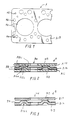
- Fig. 1 is a partial plan view of a first embodiment of a metal laminate gasket of the invention;
- Fig. 2 is an enlarged sectional view taken along a line 2-2 in Fig. 1; and
- Fig. 3 is a sectional view, similar to Fig. 2, of a metal laminate gasket according to a second embodiment of the invention.
- Referring to Figs. 1 and 2, a first embodiment A of a metal laminate gasket of the invention is shown. The gasket A is a cylinder head gasket and is situated between a cylinder head and a cylinder block (both not shown). The gasket A includes a plurality of cylinder bores Hc, water holes Hw, oil holes Ho, bolt holes Hb and so on, as in the conventional gasket.
- The invention is directed to the general structure of the gasket in association with a sealing mechanism around the water hole, so the general structure around the water hole Hw is explained. Other structures, such as sealing mechanisms for the cylinder bores Hc and so on, are not explained in the specification, but any structure may be used as desired.
- The gasket A is formed of an upper metal plate A10, a lower metal plate A11, and an intermediate metal plate A12 situated between the upper and lower metal plates A10, A11. The plates A10, A11, A12 extend substantially throughout an entire area to be sealed between the cylinder head and the cylinder block.
- The upper and lower plates A10, A11 are plane plates with holes for the water hole Hw. The intermediate plate A12 has a bead A12a around a hole for the water hole Hw. The bead A12a has a flat top portion A12b and two side portions A12c similar to a trapezoidal shape. When the bead A12a is compressed, the bead A12a provides a surface pressure to seal around the water hole Hw.
- In the gasket A, outer surface or coating layers A13 are formed on an upper surface of the upper plate A10, and a lower surface of the lower plate A11. Also, inner surface or coating layers A14 are formed on both surfaces of the intermediate plate A12. The outer coating layers A13 are made thicker than the inner coating layers A14.
- The outer coating layers A13 are formed of fluorine rubber, and the inner coating layers A14 are formed of silicone resin. These layers are coated when the plates are prepared. In addition, the outer coating layer A13 may be NBR or other materials containing rubber, and the inner coating layer A14 may be fluorine resin and epoxy resin or other materials containing suitable resin.
- In the invention, it is required that the outer coating layer A13 can fit or closely contact the cylinder head and the cylinder block, and can fill small scratches of the cylinder head and the cylinder block. Also, it is important that the inner coating layer A14 provides sliding ability between the plates of the gasket.
- When the gasket A is installed between the cylinder head and the cylinder block, the outer coating layers A13 contact the cylinder head and the cylinder block, and fill out small scratches formed in the cylinder head and the cylinder block. Since the outer coating layers A13 are not so strong against heat and pressure, the coating layers A13 may creep. However, since the outer coating layers A13 can closely contact the cylinder head and the cylinder block, even if the outer coating layers A13 creep, sealings between the cylinder head and the upper plate A10 and between the cylinder block and the lower plate All can be made properly.
- The inner coating layer A14 is formed of resin, which is strong against heat and pressure without creep relaxation, and provides a sliding ability or characteristic between the plates. Since the inner coating layers A14 do not creep, even if the outer coating layers A13 creep, the gasket A can still properly seal between the cylinder head and the cylinder block.
- When the engine with the gasket A is actuated, the cylinder head and the cylinder block expand slightly due to heat. In case the cylinder head and the cylinder block are not made of the same material, lateral stress is applied to the gasket due to the difference of heat expansion of the cylinder head and the cylinder block. In this case, the upper and lower plates A10, A11 closely contact the cylinder head and the cylinder block through the outer coating layers A13. However, since the inner coating layers A14 have a sliding characteristic, the upper and lower plates A10, A11 slightly slide relative to the intermediate plate A12 through the inner coating layers A14. Accordingly, lateral stress applied to the gasket can be absorbed properly.
- Also, in the gasket A, since the bead A12a has the flat top portion A12b, the bead A12a does not provide extremely high surface pressure at one point. Also, since the bead A12a has the inner coating layer A14 on the flat top portion A12b, when the gasket receives the lateral stress, the bead A12a can slide relative to the upper plate A10. Therefore, the inner coating is not easily peeled off from the top portion A12b of the bead A12a.
- Fig.3 is a second embodiment B of a metal laminate gasket of the invention. The gasket B is formed of an upper plate B10, a lower plate B12, and outer coating layers B13 coated on an upper surface of the plate B10 and a lower surface of the plate B12, similar to the gasket A. In the gasket B, however, there is no intermediate plate, and the lower plate B12 has a bead B12a around a water hole Hw. Also, the lower plate B12 has an inner coating layer B14 at a side facing the upper plate B10. The outer coating layers B13 are made of the same material as the outer coating layers A13, and the inner coating layer B14 is made of the same material as the inner coating layers A14.
- In the gasket B, the thickness can be made thin. However, the gasket B can operate as in the gasket A.
- In the present invention, the gasket is provided with the combination of the outer coating layers containing rubber to provide good contact with the cylinder head and the cylinder block, and the inner coating layer containing resin to provide less creep relaxation in use. Also, the inner coating layers can provide a sliding ability. Therefore, as a whole, the gasket does not creep too much, but can provide a good sealing ability relative to the cylinder head and the cylinder block, and between the plates. Also, in the invention, the gasket can properly absorb lateral stress applied to the gasket.
Claims (8)
- A metal laminate gasket (A, B) for an internal combustion engine having a fluid hole, comprising: a plurality of metal plates (A10, A11, A12; B10, B12) for constituting the metal laminate gasket; a bead (A12a, B12a) formed on one of the metal plates to surround a hole (Hw) for sealing therearound; outer surface layers (A13, B13) coated on outer surfaces of the metal laminate gasket; and at least one inner surface layer (A14, B14) coated on at least one of inner surfaces of the metal plates.
said metal laminate gasket (A, B) being characterised in a combination of the outer surface layers (A13, B13) and the at least one inner surface layer (A14, B14) , said outer surface layer (A13, B13) being formed of a material containing rubber; and said at least one inner surface layer (A14, B14) being formed of a material containing resin to provide sliding ability between the metal plates. - A metal laminate gasket (A, B) according to claim 1, wherein said outer surface layer (A13, B13) is formed of a material selected from a group consisting of fluorine rubber and NBR, and said inner surface layer (A14, B14) is formed of a material selected from a group consisting of silicone resin, fluorine resin and epoxy resin.
- A metal laminate gasket (A, B) according to either claim 1 or claim 2, wherein the thickness of the outer surface layer (A13, B13) is thicker than that of the inner surface layer (A14, B14).
- A metal laminate gasket (A, B) according to any one preceding claim, wherein said plurality of metal plates include upper and lower plates (A10, A11; B10, B12), said bead (A12a, B12a) having a flat top portion (A12b) contacts the at least one inner surface layer.
- A metal laminate gasket (A) according to claim 4, further comprising an intermediate plate (A12) situated between the upper and lower plates (A10 , A11), said intermediate plate (A12) having said bead, two inner surface layers (A14) being coated on both surfaces of the intermediate layer.
- A metal laminate gasket (B) according to claim 4, wherein said gasket is formed of only said upper and lower plates (B10, B12), said lower plate (B12) having the bead (B12a) and the inner surface layer (B14) on a surface facing the upper plate.
- A metal laminate gasket according to any one preceding claim wherein said at least one inner surface layer is formed on an inner surface of at least one of an upper or a lower plate having an outer surface layer thereon.
- A metal laminate gasket according to any one preceding claim wherein said outer surface layers and plates do not slide, in use, relative to their respective surface of an associated cylinder head and cylinder block.
Applications Claiming Priority (3)
| Application Number | Priority Date | Filing Date | Title |
|---|---|---|---|
| JP16264/96 | 1996-02-01 | ||
| JP1626496 | 1996-02-01 | ||
| JP8016264A JPH09210207A (en) | 1996-02-01 | 1996-02-01 | Metallic laminate-type gasket |
Publications (2)
| Publication Number | Publication Date |
|---|---|
| EP0787934A1 true EP0787934A1 (en) | 1997-08-06 |
| EP0787934B1 EP0787934B1 (en) | 2002-04-03 |
Family
ID=11911706
Family Applications (1)
| Application Number | Title | Priority Date | Filing Date |
|---|---|---|---|
| EP97300651A Expired - Lifetime EP0787934B1 (en) | 1996-02-01 | 1997-01-31 | Metal laminate gasket with different coating layers |
Country Status (5)
| Country | Link |
|---|---|
| US (1) | US5893566A (en) |
| EP (1) | EP0787934B1 (en) |
| JP (1) | JPH09210207A (en) |
| KR (1) | KR100227328B1 (en) |
| DE (1) | DE69711475T2 (en) |
Cited By (1)
| Publication number | Priority date | Publication date | Assignee | Title |
|---|---|---|---|---|
| WO2000036033A1 (en) * | 1998-12-15 | 2000-06-22 | Federal-Mogul Technology Limited | Gasket coating |
Families Citing this family (14)
| Publication number | Priority date | Publication date | Assignee | Title |
|---|---|---|---|---|
| JPH10259871A (en) * | 1997-03-19 | 1998-09-29 | Nippon Reinz Co Ltd | Cylinder hed gasket |
| JPH10259872A (en) * | 1997-03-19 | 1998-09-29 | Nippon Reinz Co Ltd | Cylinder hed gasket |
| DE29720941U1 (en) * | 1997-11-26 | 1998-03-19 | Gillet Heinrich Gmbh | Motor flange |
| JP2913400B1 (en) * | 1998-05-08 | 1999-06-28 | 石川ガスケット株式会社 | Metal plate gasket |
| US6247704B1 (en) * | 1998-07-30 | 2001-06-19 | Dana Corporation | Gasket with dynamic embossment |
| JP2001132582A (en) * | 1999-11-10 | 2001-05-15 | Mitsubishi Electric Corp | Fuel injection valve for cylinder injection |
| JP2002013640A (en) * | 2000-06-29 | 2002-01-18 | Uchiyama Mfg Corp | Cylinder head gasket |
| JP2002054740A (en) * | 2000-08-07 | 2002-02-20 | Ishikawa Gasket Co Ltd | Head gasket for multi-cylinder |
| US6460512B1 (en) | 2000-10-16 | 2002-10-08 | International Engine Intellectual Property Company, L.L.C. | Combustion gasket having dual material structures |
| KR100442245B1 (en) * | 2001-11-07 | 2004-07-30 | 엘지전자 주식회사 | structure for assembling drum bracket in drum-type washing machine |
| US20030151211A1 (en) * | 2002-02-11 | 2003-08-14 | Chen Colin C. | MLS gasket with variable bead stopper layer |
| DE10337677A1 (en) * | 2003-08-16 | 2005-03-17 | Federal-Mogul Sealing Systems Gmbh | Metallic flat gasket |
| US20060131817A1 (en) * | 2004-12-17 | 2006-06-22 | Kerelchuk Colin J | Gasket assembly for joints experiencing thermally induced movement |
| KR20170000076U (en) | 2016-08-18 | 2017-01-04 | 우주가스팩공업(주) | Multi kammprofile gasket |
Citations (2)
| Publication number | Priority date | Publication date | Assignee | Title |
|---|---|---|---|---|
| WO1993008420A1 (en) * | 1991-10-21 | 1993-04-29 | Mccord Payen Incorporated | Embossed composite gasket |
| US5490681A (en) * | 1994-09-22 | 1996-02-13 | Dana Corporation | Three layer metal gasket with dual coating |
Family Cites Families (3)
| Publication number | Priority date | Publication date | Assignee | Title |
|---|---|---|---|---|
| US5150910A (en) * | 1990-07-02 | 1992-09-29 | Ishikawa Gasket Co., Ltd. | Gasket with soft and hard seal coatings |
| JP2521155Y2 (en) * | 1990-08-07 | 1996-12-25 | 石川ガスケット 株式会社 | Insulating metal laminated gasket |
| US5330200A (en) * | 1992-12-04 | 1994-07-19 | Caterpillar, Inc. | Gasket assembly for sealed joints experiencing thermally induced movement |
-
1996
- 1996-02-01 JP JP8016264A patent/JPH09210207A/en active Pending
-
1997
- 1997-01-28 US US08/791,156 patent/US5893566A/en not_active Expired - Fee Related
- 1997-01-29 KR KR1019970002521A patent/KR100227328B1/en not_active IP Right Cessation
- 1997-01-31 DE DE69711475T patent/DE69711475T2/en not_active Expired - Fee Related
- 1997-01-31 EP EP97300651A patent/EP0787934B1/en not_active Expired - Lifetime
Patent Citations (2)
| Publication number | Priority date | Publication date | Assignee | Title |
|---|---|---|---|---|
| WO1993008420A1 (en) * | 1991-10-21 | 1993-04-29 | Mccord Payen Incorporated | Embossed composite gasket |
| US5490681A (en) * | 1994-09-22 | 1996-02-13 | Dana Corporation | Three layer metal gasket with dual coating |
Cited By (1)
| Publication number | Priority date | Publication date | Assignee | Title |
|---|---|---|---|---|
| WO2000036033A1 (en) * | 1998-12-15 | 2000-06-22 | Federal-Mogul Technology Limited | Gasket coating |
Also Published As
| Publication number | Publication date |
|---|---|
| EP0787934B1 (en) | 2002-04-03 |
| JPH09210207A (en) | 1997-08-12 |
| KR100227328B1 (en) | 1999-11-01 |
| KR970062436A (en) | 1997-09-12 |
| US5893566A (en) | 1999-04-13 |
| DE69711475T2 (en) | 2003-01-09 |
| DE69711475D1 (en) | 2002-05-08 |
Similar Documents
| Publication | Publication Date | Title |
|---|---|---|
| US5076595A (en) | Steel laminate gasket | |
| US5435575A (en) | Steel laminate gasket | |
| EP0787934B1 (en) | Metal laminate gasket with different coating layers | |
| US6186513B1 (en) | Method of forming gasket with annular sealing projection and groove | |
| US6682080B2 (en) | Cylinder head gasket | |
| US6139025A (en) | Metal laminate gasket with wide and narrow flange portions | |
| JPH06207672A (en) | Multilayer cylinder-head-gasket | |
| JP2002054745A (en) | Head gasket | |
| US6019376A (en) | Metal laminate gasket with wide and narrow flange portions | |
| US5695203A (en) | Metal gasket with coating layer | |
| EP0745791B1 (en) | Metal laminate gasket with coating layer | |
| US6893023B2 (en) | Metal gasket with partial coating | |
| JP2000145969A (en) | Gasket | |
| JP3709365B2 (en) | Metal gasket | |
| JP3419447B2 (en) | Head gasket | |
| EP0745792B1 (en) | Metal laminate gasket with surface pressure adjustment mechanism | |
| US5199723A (en) | Steel laminate gasket with seal protecting member | |
| US5205569A (en) | Metal laminate gasket with graphite sheet | |
| EP0518665A1 (en) | Metal laminate gasket with sealing grommet | |
| US5961126A (en) | Metal gasket with peripheral bead | |
| EP0508017B1 (en) | Metal laminate gasket with graphite sheet | |
| EP0486150B2 (en) | Steel laminate gasket with seal protecting member | |
| EP0431227B1 (en) | A steel laminate gasket | |
| US5295699A (en) | Metal laminate gasket with inner projection connecting mechanisms | |
| US5165372A (en) | Steel laminate type cylinder head gasket |
Legal Events
| Date | Code | Title | Description |
|---|---|---|---|
| PUAI | Public reference made under article 153(3) epc to a published international application that has entered the european phase |
Free format text: ORIGINAL CODE: 0009012 |
|
| AK | Designated contracting states |
Kind code of ref document: A1 Designated state(s): DE FR GB IT |
|
| 17P | Request for examination filed |
Effective date: 19970715 |
|
| 17Q | First examination report despatched |
Effective date: 20000331 |
|
| GRAG | Despatch of communication of intention to grant |
Free format text: ORIGINAL CODE: EPIDOS AGRA |
|
| GRAG | Despatch of communication of intention to grant |
Free format text: ORIGINAL CODE: EPIDOS AGRA |
|
| GRAH | Despatch of communication of intention to grant a patent |
Free format text: ORIGINAL CODE: EPIDOS IGRA |
|
| GRAH | Despatch of communication of intention to grant a patent |
Free format text: ORIGINAL CODE: EPIDOS IGRA |
|
| REG | Reference to a national code |
Ref country code: GB Ref legal event code: IF02 |
|
| GRAA | (expected) grant |
Free format text: ORIGINAL CODE: 0009210 |
|
| AK | Designated contracting states |
Kind code of ref document: B1 Designated state(s): DE FR GB IT |
|
| REF | Corresponds to: |
Ref document number: 69711475 Country of ref document: DE Date of ref document: 20020508 |
|
| ET | Fr: translation filed | ||
| PLBE | No opposition filed within time limit |
Free format text: ORIGINAL CODE: 0009261 |
|
| STAA | Information on the status of an ep patent application or granted ep patent |
Free format text: STATUS: NO OPPOSITION FILED WITHIN TIME LIMIT |
|
| 26N | No opposition filed |
Effective date: 20030106 |
|
| PGFP | Annual fee paid to national office [announced via postgrant information from national office to epo] |
Ref country code: FR Payment date: 20050110 Year of fee payment: 9 |
|
| PGFP | Annual fee paid to national office [announced via postgrant information from national office to epo] |
Ref country code: GB Payment date: 20050126 Year of fee payment: 9 |
|
| PGFP | Annual fee paid to national office [announced via postgrant information from national office to epo] |
Ref country code: DE Payment date: 20050127 Year of fee payment: 9 |
|
| PG25 | Lapsed in a contracting state [announced via postgrant information from national office to epo] |
Ref country code: GB Free format text: LAPSE BECAUSE OF NON-PAYMENT OF DUE FEES Effective date: 20060131 Ref country code: FR Free format text: LAPSE BECAUSE OF NON-PAYMENT OF DUE FEES Effective date: 20060131 |
|
| PGFP | Annual fee paid to national office [announced via postgrant information from national office to epo] |
Ref country code: IT Payment date: 20060131 Year of fee payment: 10 |
|
| PG25 | Lapsed in a contracting state [announced via postgrant information from national office to epo] |
Ref country code: DE Free format text: LAPSE BECAUSE OF NON-PAYMENT OF DUE FEES Effective date: 20060801 |
|
| GBPC | Gb: european patent ceased through non-payment of renewal fee |
Effective date: 20060131 |
|
| REG | Reference to a national code |
Ref country code: FR Ref legal event code: ST Effective date: 20060929 |
|
| PG25 | Lapsed in a contracting state [announced via postgrant information from national office to epo] |
Ref country code: IT Free format text: LAPSE BECAUSE OF NON-PAYMENT OF DUE FEES Effective date: 20070131 |