JP3685022B2 - Desk with panel - Google Patents
Desk with panel Download PDFInfo
- Publication number
- JP3685022B2 JP3685022B2 JP2000266112A JP2000266112A JP3685022B2 JP 3685022 B2 JP3685022 B2 JP 3685022B2 JP 2000266112 A JP2000266112 A JP 2000266112A JP 2000266112 A JP2000266112 A JP 2000266112A JP 3685022 B2 JP3685022 B2 JP 3685022B2
- Authority
- JP
- Japan
- Prior art keywords
- panel
- desk
- top plate
- back panel
- upper support
- Prior art date
- Legal status (The legal status is an assumption and is not a legal conclusion. Google has not performed a legal analysis and makes no representation as to the accuracy of the status listed.)
- Expired - Fee Related
Links
Images


Landscapes
- Connection Of Plates (AREA)
- Furniture Connections (AREA)
- Tables And Desks Characterized By Structural Shape (AREA)
Description
【0001】
【発明の属する技術分野】
本発明は、パネル付きデスクに係わり、更に詳しくは組立て式で棚板やキャビネットのオプションを装着することが可能なパネル付きデスクに関するものである。
【0002】
【従来の技術】
従来、天板の後縁の全面にバックパネルを立設したパネル付きデスクは公知である。また、バックパネルの前面に棚板や電話台等のオプションを取付けたデスクも各種提供されている。
【0003】
また、バックパネルとしては、金属製パネルを始めとして、クロス張りパネル、ピンナップパネル等の各種機能のパネルを採用することも一般的である。
【0004】
しかし、何れのパネル付きデスクにおいても、天板の後縁両側部に一対のバックパネルを間に空間を設けて立設したものは存在せず、またパネル付きデスクは比較的高価なOA用デスクとして提供されている。
【0005】
【発明が解決しようとする課題】
本発明は、安価で簡易な組立て式のデスクにおいて、バックパネルを間隔を置いて立設し、そのバックパネル間の空間を新たな機能空間として利用するといった全く斬新なコンセプトの基に構成し、また棚板やキャビネットとも組み合わせて商品展開自由度の高いパネル付きデスクを提供する点にある。
【0006】
【課題を解決するための手段】
本発明は、前述の課題解決のために、脚部で支持された天板の後縁両側部に縦横に複数 の貫通孔を一定間隔毎に形成したバックパネルを立設するとともに、両バックパネル間に幕体を設けてなるパネル付きデスクであって、前記バックパネルには、該バックパネルの下端を天板後縁に連結するとともに、側面視逆L字形の上部支持金具の一端を前記貫通孔を利用してバックパネルに連結し、上部支持金具の他端を天板上面側部に連結し、前記上部支持金具の一方又は両方を利用し、該上部支持金具の垂直部の背後に突設したピンに棚板の前部を載置し又は垂直部に取付けた受け金具に載置し又は垂直部にネジ止めするとともに、該棚板の後部を前記貫通孔を利用してバックパネルに連結してなるパネル付きデスクを構成した。
【0007】
また、本発明は、脚部で支持された天板の後縁両側部に縦横に複数の貫通孔を一定間隔毎に形成したバックパネルを立設するとともに、両バックパネル間に幕体を設けてなるパネル付きデスクであって、前記バックパネルには、該バックパネルの下端を天板後縁に連結するとともに、側面視逆L字形の上部支持金具の一端を前記貫通孔を利用してバックパネルに連結し、上部支持金具の他端を天板上面側部に連結し、前記上部支持金具の両方を利用し、該上部支持金具の水平部とバックパネルの上端にキャビネットを載置するとともに、該キャビネットを少なくとも前記水平部に連結してなるパネル付きデスクを構成した。
【0008】
そして、前記天板の前部両側部に円柱形状の前方脚部を設けるとともに、後部両側部に円柱形状の後方脚部を設けてなることが好ましい。
【0009】
更に、前記天板の後部両側部に、後方脚部として前記バックパネルと略同幅の脚パネルを間に空間を設けて取付けてなることも好ましい。
【0010】
【発明の実施の形態】
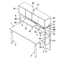
次に本発明の実施の形態を添付図面に基づき更に詳細に説明する。図1は、本発明のパネル付きデスクの基本構成である第1実施形態を示し、図中符号1は天板、2は前方脚部、3は後方脚部、4はバックパネル、5は幕体をそれぞれ示している。
【0011】
そして、本発明に係るパネル付きデスクは、前方脚部2,2と後方脚部3,3で支持された天板1の後縁両側部に一対のバックパネル4,4を間に空間6を設けて立設するとともに、両バックパネル4,4間の空間6に着脱自在に幕体5を取付けてなるものである。
【0012】
前記バックパネル4には、縦横に複数の貫通孔7,…を一定間隔毎に形成し、該バックパネル4の下端を天板1後縁に連結するとともに、側面視逆L字形の上部支持金具8の一端を、所定位置の前記貫通孔7に後方から挿入したネジ9を螺合してバックパネル4に連結し、上部支持金具8の他端を天板1上面側部に図示しないが同様にネジ止め等によって連結している。そして、前記両バックパネル4,4の空間6側の対向縁部の上下に、前記貫通孔7,…を利用してクランク状の連結金具10,…を取付け、前記空間6を埋め尽くす寸法に設定した前記幕体5を、該空間6に配して、その背面を連結金具10,…に取付けている。尚、前記バックパネル4を天板1上面に立設する構造は、互いの接合面を孔とダボで凹凸嵌合し且つ接着する方法や、公知の引付け連結金具を用いる方法を採用できる。
【0013】
ここで、前記幕体5としては、景色や模様あるいは絵を前面に形成した化粧パネルの他、通常のクロス張りパネルや木板等のパネル、布地、半透明又は透明なガラス、ホワイトボード、パンチングメタル、インシュレーションボードの中から選ばれた一種又は二種以上の複合体を用い、用途、好みに応じて採用される。つまり、前記幕板5は、前述の異なる機能を有する複数種のものを組み合わせた複合体とすることも可能である。例えば、ホワイトボードの一部にインシュレーションボードを組み込んだ構造のもの、あるいはパネルの一部にガラスを組み込んだ構造のものが挙げられる。また、前記幕体5は、連結金具10,…を介してネジ止めしているので、着脱自在であり、また変更も自由に行うことができる。更に、両バックパネル4,4間に幕体5を着脱自在に取付ける構造として、両バックパネル4,4の空間6側の対向縁部に互いに対向するように縦溝を形成し、両縦溝に幕体5の両側縁を落とし込み係合する構造でも良い。
【0014】
また、高さが異なる複数種の前記バックパネル4及び幕体5を用意しておき、前記上部支持金具8を垂直部8Aと水平部8Bからなる側面視逆L字形とし、垂直部8Aの下端に直線状の延長金具8Cを連結できる構造とすれば、用途、好みに応じてバックパネル4及び幕体5の高さも基本部品を共用して変更することができる。
【0015】
本実施形態では、前記前方脚部2は、円柱形状のものを用い、後方脚部3は前記バックパネル4と略同幅の脚パネル11を用い、天板1の後部両側部に互いの間に空間12を設けて取付けている例を示している。ここで、前記脚パネル11は、天板1の下面と該脚パネル11の上部前面とにわたって連結した下部支持金具13によって強固に取付けられている。また、前記脚パネル11は、前記バックパネル4と同様に、少なくとも上部に縦横に複数の貫通孔14,…を所定間隔を置いて設けたものを使用している。但し、前記後方脚部3も前方脚部2と同様に、円柱形状のものを用いても勿論構わない。また、前記天板1の後縁中央部には、円弧状の切欠部15を形成し、該切欠部15によって天板1と幕体5に形成される開口を利用して配線コードを挿通することができるようになっている。
【0016】
次に、本発明の各種の実施形態を図2〜図12に基づいて説明する。図2は、天板1の横幅の略半分の棚板16を左右一側に設けた第2実施形態である。前記棚板16の取付構造は、前記上部支持金具8の一方を利用し、該上部支持金具8の垂直部8Aの背後に突設したピン17(図7参照)に前記棚板16の一側前部を載置するとともに、該棚板16の後部を前記貫通孔7を利用してバックパネル4にネジ止め連結し、更に棚板16の他側前部に下設した補助支柱18を天板1に載置した取付構造となっている。尚、前記棚板16を上部支持金具8の垂直部8Aで支持する他の構造として、垂直部8Aに取付けた別の受け金具に載置する構造又は垂直部8Aに直接ネジ止めする構造を採用することもんできる。その他は、図1に示したものと同様であるので、同一構造には同一符号を付してその説明は省略する。
【0017】
また、図3は、天板1の横幅と略同幅の棚板19を設けた第3実施形態である。本実施形態では、前記上部支持金具8としてバックパネル4の略半分の高さのものを使用し、そして両側の前記上部支持金具8,8の水平部8B,8Bに棚板19の両側部を載置するとともに、該棚板19をネジ20,…で水平部8B,8Bに固定する構造としている。その他は前記同様である。
【0018】
また、図4は、第1実施形態の基本構成に、オプションとしてキャビネット21を装着した第4実施形態を示している。つまり、両側の前記上部支持金具8,8の水平部8B,8Bにスペーサ22を介して下面板23の両側部を棚板と同様に取付けるとともに、該下面板23を両バックパネル4,4の上端に載置し、そして下面板23の両側に側面板24,24とその上に上面板25を連結するとともに、背面に背面板26(図8参照)を連結し、前面に引違い扉27,…を装着してキャビネット21を構成している。前記キャビネット21は、組立て式のものを例示したが、予め箱状の完成品として作製したキャビネットでも良い。その他は前記同様である。
【0019】
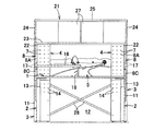
そして、図5〜図7は、前述の第2実施形態と第4実施形態を組み合わせた第5実施形態を示している。つまり、本実施形態はオプションとして横幅の小さな棚板16とキャビネット21を設けたものである。ここで、前記下部支持金具13として、上部支持金具8と同様なものを用いて脚パネル11を支持している。この場合、前記下部支持金具13の垂直部に設けたピン17を利用して、天板1の下方にも棚板を装着することが可能である。また、前記両脚パネル11,11を交叉した補強ステー28,28で連結して、横方向の強度を高めている。ここで、各補強ステー28の脚パネル11への連結には、前記貫通孔14を利用してネジ止め構造を採用している。その他は、前記同様である。
【0020】
また、図8は、第5実施形態において脚パネル11,11間の空間12にオプションとして幕シート29を装着した第6実施形態を示している。前記幕シート29は、シート体30の上下縁の袋部に縁金具31,31を挿入し、該縁金具31の両端を上下部において両脚パネル11,11に貫通孔14,…を利用して取付け、前記空間12を覆ったものである。その他は、前記同様である。
【0021】
また、図9及び図10は、第5実施形態において、横幅の狭い棚板16の代わりに第3実施形態のような横幅の広い棚板19をオプションとして設けた第7実施形態を示している。つまり、両上部支持金具8,8のピン17,17に、棚板19の前部を載置するとともに、該棚板19の両側後端を前記バックパネル4,4に貫通孔7,7を利用してネジ止めしたものである。その他は、前記同様である。
【0022】
また、図11は、第6実施形態の幕シート29の上下寸法を小さくして下部に空間12を残した第8実施形態を示している。その他は、前記同様である。
【0023】
そして、図12は、前記バックパネル4と脚パネル11を一枚の板体で一体となした第9実施形態を示している。この場合、前方脚部2として伸縮可能なものを用いれば、前記天板1を装着するバックパネル4の貫通孔7又は脚パネル11の貫通孔14の位置を変えることで、天板1の高さを調節することができる。また、脚パネル11と一体であるバックパネル4の支持強度は飛躍的に高くなるので好ましい。その他は、前記同様である。
【0024】
また、図13は、前記第2実施形態において、棚板16を上部支持金具8を用いずに支持した第10実施形態を示している。つまり、2本の補助支柱18,18を棚板16の前部下面両側に垂下し、天板1の上面に載置するとともに、棚板16の後端適所をバックパネル4に貫通孔7,…を利用してネジ止めしたものである。
【0025】
また、図14は、図1に示した下部支持金具13を利用して天板1の下方奥部に配線ダクトを設けた第11実施形態を示している。ここで、前記下部支持金具13は、天板1と脚パネル11とを剛性的に連結するために、垂直板13Aを有している。そして、前記下部支持金具13の垂直板13Aには開口13B(図1参照)を形成し、両下部支持金具13,13の開口13B,13Bにダクトパイプ32を貫通させて保持し、該ダクトパイプ32内に配線コードを挿通できるようにしたものである。
【0026】
更に、図15〜図19は、オプションとして小物入れ33をバックパネル4に装着した第12実施形態を示している。本実施形態の小物入れ33は、図16に示すように、略四角形のシート体34の8箇所に孔35,…を開口したものを用いて構成する。図16において、左端上下の孔35A1,35A2の間隔をAとし、中央左寄り上下の孔35B1,35B2の間隔をBとし、中央右寄り上下の孔35C1,35C2の間隔をCとし、右端上下の孔35D1,35D2の間隔をDとすれば、A>D、B>C、C=Dとなるように設定している。また、孔35C1,35C2と孔35D1,35D2は、前記バックパネル4の貫通孔7,…の位置に一致させている。
【0027】
そして、図17に示すように、前記シート体34を中央部で折り返し、前記孔35A1,35A2と孔35D1,35D2とをそれぞれ重ね合わせて、前記貫通孔7,7に締結具36,36で取付けるとともに、同様に前記孔35B1,35B2と孔35C1,35C2とをそれぞれ重ね合わせて、前記貫通孔7,7に締結具36,36で取付けると、バックパネル4側に位置するシート部37は略バックパネル4表面に沿った形状となり、表側に位置するシート部38は手前に膨らんだ形状となり、このシート部38の膨らみによって上方へ開放した収納空間39が形成されるので、この空間に上方から筆記具や定規等の小物を収納することができる。
【0028】
また、図18に示すように、前記シート体34を中央部で折り返し、前記孔35A1,35A2と孔35D1,35D2とをそれぞれ重ね合わせて、前記貫通孔7,7に締結具36,36で取付けると、シート体34の折り返し部40が丸く膨らんだ形状となり、側方へ開放した収納空間41が形成されるので、この空間に横方向から長尺の小物を挿入して収納することができる。
【0029】
ここで、前記締結具36は、図19に示すように従来から公知のものである。つまり、前記締結具36は、頭付きの雄ネジ36Aと頭付きの雌ネジ36Bのセットとなっており、例えば図示するように、孔35A1と孔35D1とに雄ネジ36Aを通して所定の貫通孔7に表側から挿入し、他方貫通孔7の裏側から雌ネジ36Bを挿入して貫通孔7内で互いに螺合して取付けるものである。
【0030】
このように、各部品を全て組立て式にすることにより、在庫管理、搬送が容易になり、更には部品の組合せやオプションの追加、変更により商品展開の自由度は高くなり、ニーズに合ったパネル付きデスクを提供できるのである。
【0031】
【発明の効果】
以上にしてなる請求項1に係る発明のパネル付きデスクによれば、縦横に複数の貫通孔を一定間隔毎に形成したバックパネルの間に、使用者の用途、好みに合わせて様々な幕体を装着することができ、また構造が簡単であるので安価に提供できるのである。また、バックパネルの貫通孔を利用して、幕体や棚板などのオプションを取付けることができ、また高さの異なる上部支持金具を取付けることができ、更に棚板の取付け高さ、横方向位置に対する自由度が高まるのである。更に、棚板を簡単に取付けることができ、しかも棚板の取付け高さ、横方向位置に対する自由度が高まるのである。
【0032】
請求項2によれば、縦横に複数の貫通孔を一定間隔毎に形成したバックパネルの間に、使用者の用途、好みに合わせて様々な幕体を装着することができ、また構造が簡単であるので安価に提供できるのである。また、バックパネルの貫通孔を利用して、幕体や棚板などのオプションを取付けることができ、また高さの異なる上部支持金具を取付けることができ、更に棚板の取付け高さ、横方向位置に対する自由度が高まるのである。更に、バックパネルの上部にキャビネットを簡単に取付けることができ、その支持強度も高いものとなる。
【0033】
請求項3によれば、4本の円柱形状の脚部で天板を支持することができる。
【0034】
請求項4によれば、バックパネルと脚パネルとが、天板上下でバランス良く配置されるので、外観性に優れるとともに、両脚パネル間の空間を利用して通気や、配線コードの配設が可能となる。
【図面の簡単な説明】
【図1】 本発明のパネル付きデスクの第1実施形態を示す斜視図である。
【図2】 第2実施形態を示す斜視図である。
【図3】 第3実施形態を示す斜視図である。
【図4】 第4実施形態を示す斜視図である。
【図5】 第5実施形態を示す斜視図である。
【図6】 同じく第5実施形態を示す正面図である。
【図7】 同じく第5実施形態を示す側面図である。
【図8】 第6実施形態を示す斜視図である。
【図9】 第7実施形態を示す正面図である。
【図10】 同じく第7実施形態を示す側面図である。
【図11】 第8実施形態を示す斜視図である。
【図12】 第9実施形態を示す側面図である。
【図13】 第10実施形態を示す斜視図である。
【図14】 第11実施形態を示す正面図である。
【図15】 第12実施形態を示す斜視図である。
【図16】 同じく第12実施形態を示すシート体の平面図図である。
【図17】 同じく第12実施形態の第1使用例を示す斜視図である。
【図18】 同じく第12実施形態の第2使用例を示す斜視図である。
【図19】 同じく第12実施形態を示す部分断面図である。
【符号の説明】
1 天板 2 前方脚部
3 後方脚部 4 バックパネル
5 幕体 6 空間
7 貫通孔 8 上部支持金具
8A 垂直部 8C 延長金具
8B 水平部 9 ネジ
10 連結金具 11 脚パネル
12 空間 13 下部支持金具
14 貫通孔 15 切欠部
16 棚板 17 ピン
18 補助支柱 19 棚板
20 ネジ 21 キャビネット
22 スペーサ 23 下面板
24 側面板 25 上面板
26 背面板 27 引違い扉
28 補強ステー 29 幕シート
30 シート体 31 縁金具
32 ダクトパイプ 33 小物入れ
34 シート体 35 孔
36 締結具 37 シート部
38 シート部 39 収納空間
40 折り返し部 41 収納空間[0001]
BACKGROUND OF THE INVENTION
The present invention relates to a panel-equipped desk, and more particularly to a panel-equipped desk that can be assembled and can be mounted with shelf and cabinet options.
[0002]
[Prior art]
Conventionally, a desk with a panel in which a back panel is erected on the entire rear edge of the top plate is known. Various desks with options such as shelves and telephone stands on the front of the back panel are also available.
[0003]
In addition, as a back panel, it is common to employ a panel having various functions such as a metal panel, a cross tension panel, and a pinup panel.
[0004]
However, none of the desks with panels have a pair of back panels standing on both sides of the rear edge of the top plate with a space between them, and desks with panels are relatively expensive OA desks. Is offered as.
[0005]
[Problems to be solved by the invention]
The present invention is based on a completely novel concept such as a cheap and simple assembling-type desk with standing back panels at intervals and using the space between the back panels as a new functional space. In addition, the combination with shelves and cabinets provides a panel desk with a high degree of freedom in product development.
[0006]
[Means for Solving the Problems]
In order to solve the above-mentioned problems, the present invention erects a back panel in which a plurality of through holes are formed at regular intervals on both sides of the rear edge of the top plate supported by the legs , and both back panels A desk with a panel provided with a curtain in between, the lower end of the back panel is connected to the rear edge of the top plate, and one end of an upper support fitting having an inverted L shape in side view is passed through the back panel. Connect to the back panel using the holes, connect the other end of the upper support bracket to the top plate side, and use one or both of the upper support brackets to project behind the vertical portion of the upper support bracket. The front part of the shelf board is placed on the provided pin or placed on a receiving metal fitting attached to the vertical part or screwed to the vertical part, and the rear part of the shelf board is attached to the back panel using the through hole. Constructed a desk with a panel.
[0007]
The present invention also has a back panel in which a plurality of through-holes are formed at regular intervals on both sides of the rear edge of the top plate supported by the legs, and a curtain is provided between the back panels. The lower panel has a lower end coupled to the rear edge of the top plate, and one end of an inverted L-shaped upper support fitting is connected to the back panel using the through hole. Connect to the panel, connect the other end of the upper support bracket to the top side of the top plate, and use both of the upper support bracket to place the cabinet on the horizontal part of the upper support bracket and the upper end of the back panel A panel-equipped desk is formed by connecting the cabinet to at least the horizontal portion.
[0008]
And it is preferable to provide a column-shaped front leg part on the both sides of the front part of the top plate, and to provide a columnar rear leg part on both sides of the rear part.
[0009]
Furthermore, it is also preferable that leg panels having substantially the same width as the back panel are provided as rear legs on both sides of the rear part of the top plate with a space therebetween.
[0010]
DETAILED DESCRIPTION OF THE INVENTION
Next, embodiments of the present invention will be described in more detail with reference to the accompanying drawings. FIG. 1 shows a first embodiment as a basic structure of a desk with a panel according to the present invention, in which
[0011]
The desk with a panel according to the present invention has a pair of
[0012]
A plurality of through-
[0013]
Here, as the
[0014]
Also, a plurality of types of the
[0015]
In the present embodiment, the
[0016]
Next, various embodiments of the present invention will be described with reference to FIGS. FIG. 2 is a second embodiment in which
[0017]
FIG. 3 shows a third embodiment in which a
[0018]
FIG. 4 shows a fourth embodiment in which a
[0019]
5 to 7 show a fifth embodiment in which the second embodiment and the fourth embodiment described above are combined. That is, in this embodiment, a
[0020]
FIG. 8 shows a sixth embodiment in which a
[0021]
9 and 10 show a seventh embodiment in which, in the fifth embodiment, a
[0022]
FIG. 11 shows an eighth embodiment in which the vertical dimension of the
[0023]
FIG. 12 shows a ninth embodiment in which the
[0024]
FIG. 13 shows a tenth embodiment in which the
[0025]
FIG. 14 shows an eleventh embodiment in which a wiring duct is provided in the lower back part of the
[0026]
15 to 19 show a twelfth embodiment in which an
[0027]
Then, as shown in FIG. 17, the
[0028]
Further, as shown in FIG. 18, the
[0029]
Here, the
[0030]
In this way, by making all parts assembling, inventory management and transportation become easy, and the degree of freedom of product development is increased by adding and changing parts combinations and options, and a panel that meets your needs. A desk with a desk can be provided.
[0031]
【The invention's effect】
According to the panel-equipped desk of the invention according to
[0032]
According to the second aspect, various curtains can be mounted between the back panel in which a plurality of through holes are formed at regular intervals in the vertical and horizontal directions according to the user's application and preference, and the structure is simple. Therefore, it can be provided at a low cost. Also, options such as curtains and shelves can be installed using the through holes in the back panel, and upper support brackets with different heights can be installed. The degree of freedom for the position increases. Further, the cabinet can be easily attached to the upper portion of the back panel, and the supporting strength is high.
[0033]
According to the third aspect , the top plate can be supported by the four columnar legs.
[0034]
According to
[Brief description of the drawings]
FIG. 1 is a perspective view showing a first embodiment of a desk with a panel according to the present invention.
FIG. 2 is a perspective view showing a second embodiment.
FIG. 3 is a perspective view showing a third embodiment.
FIG. 4 is a perspective view showing a fourth embodiment.
FIG. 5 is a perspective view showing a fifth embodiment.
FIG. 6 is a front view showing the fifth embodiment.
FIG. 7 is a side view showing the fifth embodiment.
FIG. 8 is a perspective view showing a sixth embodiment.
FIG. 9 is a front view showing a seventh embodiment.
FIG. 10 is a side view showing the seventh embodiment.
FIG. 11 is a perspective view showing an eighth embodiment.
FIG. 12 is a side view showing a ninth embodiment.
FIG. 13 is a perspective view showing a tenth embodiment.
FIG. 14 is a front view showing an eleventh embodiment.
FIG. 15 is a perspective view showing a twelfth embodiment.
FIG. 16 is a plan view of a sheet body similarly showing a twelfth embodiment.
FIG. 17 is a perspective view showing a first usage example of the twelfth embodiment.
FIG. 18 is a perspective view showing a second usage example of the twelfth embodiment.
FIG. 19 is a partial sectional view showing the twelfth embodiment.
[Explanation of symbols]
DESCRIPTION OF
Claims (4)
Priority Applications (1)
| Application Number | Priority Date | Filing Date | Title |
|---|---|---|---|
| JP2000266112A JP3685022B2 (en) | 2000-09-01 | 2000-09-01 | Desk with panel |
Applications Claiming Priority (1)
| Application Number | Priority Date | Filing Date | Title |
|---|---|---|---|
| JP2000266112A JP3685022B2 (en) | 2000-09-01 | 2000-09-01 | Desk with panel |
Publications (2)
| Publication Number | Publication Date |
|---|---|
| JP2002065364A JP2002065364A (en) | 2002-03-05 |
| JP3685022B2 true JP3685022B2 (en) | 2005-08-17 |
Family
ID=18753260
Family Applications (1)
| Application Number | Title | Priority Date | Filing Date |
|---|---|---|---|
| JP2000266112A Expired - Fee Related JP3685022B2 (en) | 2000-09-01 | 2000-09-01 | Desk with panel |
Country Status (1)
| Country | Link |
|---|---|
| JP (1) | JP3685022B2 (en) |
Families Citing this family (8)
| Publication number | Priority date | Publication date | Assignee | Title |
|---|---|---|---|---|
| JP4408038B2 (en) * | 2003-10-31 | 2010-02-03 | 株式会社岡村製作所 | Partition plate mounting device for desk |
| JP4358598B2 (en) * | 2003-10-31 | 2009-11-04 | 株式会社岡村製作所 | Mounting structure of partition plate on table top plate |
| JP4899996B2 (en) * | 2007-03-30 | 2012-03-21 | 株式会社イトーキ | Upper cabinet device at desk |
| JP5806182B2 (en) * | 2012-08-29 | 2015-11-10 | コイズミファニテック株式会社 | Unit desk |
| JP2015188509A (en) * | 2014-03-27 | 2015-11-02 | 株式会社岡村製作所 | Panel unit and furniture system |
| CN106263509B (en) * | 2015-06-15 | 2019-10-15 | 北京世纪京泰家具有限公司 | The assembling method of pin-connected panel desk |
| CN106617799A (en) * | 2016-12-12 | 2017-05-10 | 广东艾比办公设备制品有限公司 | Screen office table board installation structure |
| JP7266771B2 (en) * | 2018-09-27 | 2023-05-01 | コクヨ株式会社 | knockdown table or counter |
-
2000
- 2000-09-01 JP JP2000266112A patent/JP3685022B2/en not_active Expired - Fee Related
Also Published As
| Publication number | Publication date |
|---|---|
| JP2002065364A (en) | 2002-03-05 |
Similar Documents
| Publication | Publication Date | Title |
|---|---|---|
| US4432590A (en) | Structural system for supporting furniture, shelf and wall panels | |
| JP2000505346A (en) | Modular indoor equipment system | |
| US20100090567A1 (en) | Storage furniture system and methods for assembling the storage furniture system | |
| JP3685022B2 (en) | Desk with panel | |
| WO1987003321A1 (en) | Panel structures | |
| JP2000287760A (en) | Device for attaching option to table | |
| JP3913511B2 (en) | Frame structure, and frame structure and desk | |
| KR20180027097A (en) | Multifunctional furniture | |
| JP4520476B2 (en) | System furniture with desk and bookshelf | |
| JP3910110B2 (en) | Partition device | |
| JPH0522Y2 (en) | ||
| JP2001145526A (en) | Screen panel mounting device for desk | |
| JP2870688B2 (en) | Folding unit structure | |
| JP2001169833A (en) | Desk device | |
| CN219982374U (en) | Folding table | |
| JP7519855B2 (en) | Counter device | |
| JP3811612B2 (en) | Support device for desk | |
| JP4277190B2 (en) | Counter system | |
| US20100095614A1 (en) | Modular wall system | |
| KR200316973Y1 (en) | An exhibition display stand enabling shelves to widen | |
| JP7496266B2 (en) | Partitioning device | |
| JPH08308648A (en) | Cabinet structure of assembling shelf | |
| JPH0727877Y2 (en) | Partition panel mounting structure for desks, etc. | |
| JPH04136150U (en) | Unit furniture consisting of reconfigurable shelves and desks | |
| JPS6211470Y2 (en) |
Legal Events
| Date | Code | Title | Description |
|---|---|---|---|
| A977 | Report on retrieval |
Free format text: JAPANESE INTERMEDIATE CODE: A971007 Effective date: 20041014 |
|
| A131 | Notification of reasons for refusal |
Free format text: JAPANESE INTERMEDIATE CODE: A131 Effective date: 20041026 |
|
| A521 | Written amendment |
Free format text: JAPANESE INTERMEDIATE CODE: A523 Effective date: 20041220 |
|
| TRDD | Decision of grant or rejection written | ||
| A01 | Written decision to grant a patent or to grant a registration (utility model) |
Free format text: JAPANESE INTERMEDIATE CODE: A01 Effective date: 20050510 |
|
| A61 | First payment of annual fees (during grant procedure) |
Free format text: JAPANESE INTERMEDIATE CODE: A61 Effective date: 20050523 |
|
| R150 | Certificate of patent or registration of utility model |
Free format text: JAPANESE INTERMEDIATE CODE: R150 |
|
| S533 | Written request for registration of change of name |
Free format text: JAPANESE INTERMEDIATE CODE: R313533 |
|
| R370 | Written measure of declining of transfer procedure |
Free format text: JAPANESE INTERMEDIATE CODE: R370 |
|
| LAPS | Cancellation because of no payment of annual fees |