KR20180027097A - Multifunctional furniture - Google Patents
Multifunctional furniture Download PDFInfo
- Publication number
- KR20180027097A KR20180027097A KR1020160114257A KR20160114257A KR20180027097A KR 20180027097 A KR20180027097 A KR 20180027097A KR 1020160114257 A KR1020160114257 A KR 1020160114257A KR 20160114257 A KR20160114257 A KR 20160114257A KR 20180027097 A KR20180027097 A KR 20180027097A
- Authority
- KR
- South Korea
- Prior art keywords
- upper plate
- inner frame
- furniture
- frame
- frames
- Prior art date
- Legal status (The legal status is an assumption and is not a legal conclusion. Google has not performed a legal analysis and makes no representation as to the accuracy of the status listed.)
- Ceased
Links
Images



Classifications
-
- A—HUMAN NECESSITIES
- A47—FURNITURE; DOMESTIC ARTICLES OR APPLIANCES; COFFEE MILLS; SPICE MILLS; SUCTION CLEANERS IN GENERAL
- A47B—TABLES; DESKS; OFFICE FURNITURE; CABINETS; DRAWERS; GENERAL DETAILS OF FURNITURE
- A47B13/00—Details of tables or desks
- A47B13/02—Underframes
-
- A—HUMAN NECESSITIES
- A47—FURNITURE; DOMESTIC ARTICLES OR APPLIANCES; COFFEE MILLS; SPICE MILLS; SUCTION CLEANERS IN GENERAL
- A47B—TABLES; DESKS; OFFICE FURNITURE; CABINETS; DRAWERS; GENERAL DETAILS OF FURNITURE
- A47B13/00—Details of tables or desks
- A47B13/08—Table tops; Rims therefor
-
- A—HUMAN NECESSITIES
- A47—FURNITURE; DOMESTIC ARTICLES OR APPLIANCES; COFFEE MILLS; SPICE MILLS; SUCTION CLEANERS IN GENERAL
- A47B—TABLES; DESKS; OFFICE FURNITURE; CABINETS; DRAWERS; GENERAL DETAILS OF FURNITURE
- A47B3/00—Folding or stowable tables
- A47B3/06—Folding or stowable tables with separable parts
- A47B3/063—Folding or stowable tables with separable parts combined with seats
-
- A—HUMAN NECESSITIES
- A47—FURNITURE; DOMESTIC ARTICLES OR APPLIANCES; COFFEE MILLS; SPICE MILLS; SUCTION CLEANERS IN GENERAL
- A47B—TABLES; DESKS; OFFICE FURNITURE; CABINETS; DRAWERS; GENERAL DETAILS OF FURNITURE
- A47B9/00—Tables with tops of variable height
-
- A—HUMAN NECESSITIES
- A47—FURNITURE; DOMESTIC ARTICLES OR APPLIANCES; COFFEE MILLS; SPICE MILLS; SUCTION CLEANERS IN GENERAL
- A47C—CHAIRS; SOFAS; BEDS
- A47C11/00—Benches not otherwise provided for
-
- A—HUMAN NECESSITIES
- A47—FURNITURE; DOMESTIC ARTICLES OR APPLIANCES; COFFEE MILLS; SPICE MILLS; SUCTION CLEANERS IN GENERAL
- A47C—CHAIRS; SOFAS; BEDS
- A47C13/00—Convertible chairs, stools or benches
-
- A—HUMAN NECESSITIES
- A47—FURNITURE; DOMESTIC ARTICLES OR APPLIANCES; COFFEE MILLS; SPICE MILLS; SUCTION CLEANERS IN GENERAL
- A47C—CHAIRS; SOFAS; BEDS
- A47C17/00—Sofas; Couches; Beds
- A47C17/04—Seating furniture, e.g. sofas, couches, settees, or the like, with movable parts changeable to beds; Chair beds
Landscapes
- Health & Medical Sciences (AREA)
- General Health & Medical Sciences (AREA)
- Nursing (AREA)
- Combinations Of Kitchen Furniture (AREA)
Abstract
본 발명은 다기능 가구에 관한 것으로서, 상판(110)과; 각각 상호 대향하는 한 쌍으로 이루어진 상·하측 수평프레임(121,122)과 좌·우측 수직프레임(123,124)을 결합하여 골격을 형성하고 중심부에는 사각 형상의 개방부(125)를 구비하는 외부프레임(120)과; 수평바(131)와, 수평바(131)의 양측 하부에서 상호 대향하도록 결합하는 한 쌍의 수직바(132,133)를 결합하여 형성하는 내부프레임(130)을 포함하여 이루어지고; 상기 외부프레임(120)의 개방부(125)의 내측에는 상기 내부프레임(130)을 조립하여 상판지지부(140)를 형성하고; 상기 상판지지부(140)는 복수를 구비하고 상측 수평프레임(121)과 수평바(131) 상간의 이격부 상에 상기 상판(110)의 양단을 인입하여 상판(110)과 조립하는 것을 포함하여 구성함에 따라 필요에 따라 간편하게 다양한 기능성의 가구를 구현하여 사용할 수 있는 것이 특징이다.The present invention relates to a multifunctional furniture comprising: an upper panel (110); An outer frame 120 having a skeleton formed by a pair of upper and lower horizontal frames 121 and 122 and left and right vertical frames 123 and 124 which are opposed to each other and having a square opening 125 at the center, and; A horizontal bar 131 and an inner frame 130 formed by combining a pair of vertical bars 132 and 133 which are mutually opposed to each other at both lower sides of the horizontal bar 131; The inner frame 130 is assembled to the inside of the opening 125 of the outer frame 120 to form an upper plate supporting part 140; The upper plate supporting part 140 includes a plurality of the upper plate supporting parts 140 and the upper plate 110 and the upper plate supporting part 140, It is easy to implement various functional furniture according to need.
Description
본 발명은 다기능 가구에 관한 것으로서 더욱 상세하게는 상판 및 상판지지부를 구성하는 각 요소의 선택적인 조합에 의해 다양한 구조를 형성하도록 구성함으로써 필요에 따라 간편하게 다양한 기능성을 구현할 수 있는 다기능 가구의 제공에 관한 것이다.The present invention relates to a multifunctional furniture, and more particularly, to a multifunctional furniture which can be configured to have various structures by selectively combining the elements constituting the upper plate and the upper plate support, will be.
일반적으로, 가구는 실내에 배치하여 일상생활 또는 특정 목적의 작업용으로 사용하도록 구비된다. 가구는 주로 목재, 금속강판, 유리, 플라스틱, 가죽 등의 재질로 이루어지며 사용 목적, 구조, 기능 등에 따라 다양한 종류로 분류할 수 있다.In general, the furniture is arranged indoors so that it can be used for daily life or for a specific purpose. The furniture is mainly made of wood, metal plate, glass, plastic, leather, etc., and can be classified into various kinds according to purpose, structure, and function.
먼저, 사용 목적에 따라서는 침대, 장롱, 소파 등의 주거용 가구와, 작업대, 벤치, 사물함 등의 공공용 가구와, 카운터, 진열대 등의 상업용 가구로 분류할 수 있다.First, depending on the purpose of use, residential furniture such as a bed, a dresser, a sofa, a public furniture such as a work bench, a bench, a locker, and a commercial furniture such as a counter and a shelf can be categorized.
구조에 따라서는 위치를 옮길 수 있도록 설계된 일반적인 가구 형태인 가동 가구와, 건축물에 고정시킨 가구로서 붙박이 가구와, 일정한 모듈에 따라 설계되고 크기의 증감을 자유자재로 조절할 수 있는 조립식 가구가 있다.Depending on the structure, there are moving furniture, which is a general furniture type designed to move its position, built-in furniture, and prefabricated furniture designed according to certain modules and freely adjustable in size.
기능에 따라서는 작업대, 싱크대, 책상 등의 작업용 가구와, 침대, 소파, 의자 등의 휴식용 가구, 장농, 책장 등 물건을 정리하고 보관하는 수납용 가구가 있다.Depending on the functions, there are working furniture such as a work desk, a sink, a desk, and furniture for restoration such as a bed, a sofa, a chair, rest furniture, a dresser, a book shelf and the like.
한편, 최근에는 한정된 공간 내에서 가구의 형태 또는 배치를 효율적으로 활용하는 인테리어에 대한 관심이 높아지고, 특히 서로 다른 기능성을 가진 가구를 하나로 접목시킨 형태의 가구가 주목받고 있어 관련 기술의 개발이 활발하게 이루어지고 있다.In recent years, there has been a growing interest in interiors that efficiently utilize the form or arrangement of furniture within a limited space, and in particular, furniture in a form of combining furniture having different functions into one is attracting attention, .
예컨대, 등록실용신안 제20-0423240호에는 소파를 침대용으로 겸하여 사용할 수 있는 가구가 공지된 바 있으므로, 그 개략적인 구성을 살펴보면 다음과 같다.For example, since a furniture which can be used as a sofa for a bed together is known in the registration utility model No. 20-0423240, the outline of the structure will be described below.
소파와 침대를 겸하는 소파겸용 침대에 있어서, 좌우 양측에 일정 폭과 높이를 갖게 형성되는 좌우 측면고정판과, 좌우 측면고정판 간에 일정 길이를 갖게 구비되는 베드와, 상기 좌우 측면고정판 내측면에 구비되어 돌출되며 상기 베드의 후방 측을 관통하여 회동시키는 힌지축과, 상기 베드의 하부면과 맞닿으며 일정 폭을 갖게 형성되고 상기 좌우 측면 고정판에 고정되는 소파와, 소파 하부면을 지지하며 상기 좌우 측면고정판 간을 연결하여 고정시키는 적어도 1개 이상의 덧판을 포함하여 구성된다.A bed for a sofa and a sofa bed, comprising: a bed having left and right side fixing plates formed to have a predetermined width and height at both left and right sides and a fixed length between left and right side fixing plates; A sofa fixed to the left and right side fixing plates and formed to have a constant width in contact with the lower surface of the bed, a support member supporting the lower surface of the sofa, And at least one or more slats for connecting and fixing the slats.
또 다른 예로는, 등록실용신안 제20-0200821호의 책상 겸용 책장이 공지된 바 있으며, 내부에 책을 올려놓는 받침판 및 받침테이블이 구비된 책장과, 물건을 수납하는 이동식 서랍장과, 상기 책장의 받침테이블 및 이동식서랍장에 놓이는 보조테이블로 구성되고, 상기 책장의 받침테이블과 보조테이블의 일단부가 제1회전수단에 의해 회전 가능하게 결합되고, 상기 이동식서랍장의 상면과 보조테이블의 타단부가 제2회전수단에 의해 회전 가능하게 결합되는 것을 포함하여 구성된다.As another example, there has been known a desk-like bookcase of Registration Practical Utility Model No. 20-0200821, which includes a bookcase having a base plate and a base table on which a book is placed, a movable type of drawer for storing articles, Wherein the upper surface of the movable drawer and the other end of the auxiliary table are rotatably coupled to each other by a first rotation means and a second rotation means, And rotatably coupled by means.
상기와 같은 종래 기술이 적용되는 소파 겸용 침대는 일반적인 1인용 침대의 베드를 상하로 회동시켜 내측에 구비된 소파를 겸하여 사용하도록 하는 접이식 가구의 형태를 취하고 있다.The sofa combined bed to which the above-described conventional technique is applied is in the form of a folding-type furniture in which a bed of a general single bed is vertically rotated so as to be used as a sofa provided inside.
그러나, 상기 종래 기술은 상기 베드를 힌지축을 기점으로 단순 회동하는 작동에 의해서 베드의 하측에 구비된 소파를 노출시키도록 구성되어 침대 또는 소파의 2가지의 기능만을 구현할 수 있는 한계가 있다.However, the above-mentioned prior art has a limitation in that only the two functions of a bed or a sofa can be realized by constituting the bed so as to expose a sofa provided on the lower side of the bed by a simple rotation of the bed from the hinge axis.
특히, 상기 베드, 소파, 및 이들 양측을 고정하는 좌우 측면고정판에 의해 가구의 기본적인 형틀이 고정되므로 침대 또는 소파로 용도를 변경하더라도 가구의 전체적인 구조는 고정된 틀에서 크게 벗어나지 못하는 한계가 있다.Particularly, since the basic molds of the furniture are fixed by the bed, the sofa, and the left and right side fixing plates for fixing the both sides, there is a limit in that the overall structure of the furniture can not be largely deviated from the fixed frame even if the usage is changed as a bed or a sofa.
한편, 또 다른 예로든 종래 기술의 책상 겸용 책장은 일반적인 책장에 보조테이블 및 이동식서랍장을 회전 가능하게 결합하여 책장 또는 책상을 겸하여 사용하도록 하는 형태를 취하고 있다.Meanwhile, as another example of the conventional desk-like bookcase, the auxiliary table and the movable drawer are rotatably coupled to a general bookcase so that a bookcase or a desk can be used together.
즉, 종래 기술의 책상 겸용 책장 역시 책장에 고정된 받침테이블의 저면에 구비되는 상기 보조테이블을 회전수단에 의해 힌지축을 기점으로 전후로 회동하여 책장 외부로 노출시키도록 구성되므로 기본적으로는 책장이 주된 가구로 구성되며 보조적으로 책상의 기능을 수행할 수 있으므로 기능적인 면에서는 책장 또는 책상이라는 2가지 기능에만 국한되며, 전술한 종래 기술과 마찬가지로 전체적인 구조의 변경은 실질적으로 극히 제한적인 단점이 있다.That is, the conventional desk-top bookcase also has the auxiliary table, which is provided on the bottom surface of the base table fixed to the bookcase, is rotated around the hinge axis by the rotation means to expose the auxiliary table to the outside of the bookcase. Basically, And functions as a desk. Therefore, the function is limited to only two functions, i.e., a bookcase or a desk, and the overall structure change is substantially limited as in the case of the conventional technology described above.
이에 본 발명에서는 상술한 바와 같은 문제점을 해결하기 위하여 발명한 것으로서,Accordingly, the present invention has been made to solve the above-mentioned problems,
상판(110)과;An
각각 상호 대향하는 한 쌍으로 이루어진 상·하측 수평프레임(121,122)과 좌·우측 수직프레임(123,124)을 결합하여 골격을 형성하고 중심부에는 사각 형상의 개방부(125)를 구비하는 외부프레임(120)과;An
수평바(131)와, 수평바(131)의 양측 하부에서 상호 대향하도록 결합하는 한 쌍의 수직바(132,133)를 결합하여 형성하는 내부프레임(130)을 포함하여 이루어지고;A
상기 외부프레임(120)의 개방부(125)의 내측에는 상기 내부프레임(130)을 조립하여 상판지지부(140)를 형성하고;The
상기 상판지지부(140)는 복수를 구비하고 상측 수평프레임(121)과 수평바(131) 상간의 이격부 상에 상기 상판(110)의 양단을 인입하여 상판(110)과 조립하도록 구성함으로써 필요에 따라 간편하게 다양한 기능성을 구현할 수 있는 가구를 제공하는 목적 달성이 가능하다.The upper
본 발명은 상판 및 상판지지부를 구성하는 각 요소의 선택적인 조합에 의해 다양한 구조를 형성하도록 구성함에 따라 사용자가 설치환경 또는 필요에 따라 가구의 구조를 자유롭게 변경하여 다양한 기능성을 구현할 수 있는 이점이 있다.According to the present invention, various structures are formed by selective combination of the elements constituting the upper plate and the upper plate supporting part, the user can freely change the structure of the furniture according to the installation environment or need, .
예컨대, 본 발명의 1 실시 예와 같은 장의자의 형태나 2 실시 예와 같은 테이블 또는 책상, 3 실시 예와 같은 침대 프레임 등 다양한 가구의 기능성을 구현하는 것이 가능하다.For example, it is possible to implement the functionality of various furniture such as a form of a clerk like one embodiment of the present invention, a table or desk as in the second embodiment, and a bed frame as in the third embodiment.
특히, 상판 또는 외부프레임 및 내부프레임을 구성하는 세부 구성요소별로 그 크기를 자유롭게 변형하여 다양한 사이즈 및 형상의 상판 및 상판지지부를 구비함으로써 사용자가 원하는 구조에 맞게 조립하여 다양한 기능성 및 디자인의 가구를 구현할 수 있는 이점이 있다.Particularly, it is possible to freely modify the size of each of the detailed components constituting the upper plate or the outer frame and the inner frame to provide the upper plate and the upper plate supporting part of various sizes and shapes, There is an advantage to be able to.
따라서, 자유로운 구조 변경을 통해 원하는 형태 및 크기, 기능성을 가지는 가구를 간편하게 구현할 수 있어 공간 활용도를 높힐 수 있음은 물론 실용성과 기능성을 두루 갖춘 다기능 가구를 제공할 수 있는 이점이 있다.Accordingly, it is possible to easily implement furniture having a desired shape, size, and functionality through a free structural change, thereby increasing space utilization and providing a multifunctional furniture with practicality and functionality.
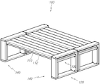
도 1은 본 발명의 다기능 가구의 1 실시 예에 따른 사시도.
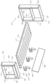
도 2는 본 발명의 다기능 가구의 1 실시 예에 따른 분해 사시도.
도 3은 본 발명의 다기능 가구의 1 실시 예에 따른 우측면도.
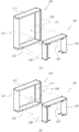
도 4는 본 발명의 다기능 가구의 1 실시 예에 따른 상판지지부의 분해도.
도 5는 본 발명의 다기능 가구의 상판지지부의 다양한 실시 예를 도시한 예시도.
도 6 내지 도 7은 본 발명의 다기능 가구의 2 실시 예 및 3 실시 예를 도시한 예시도.1 is a perspective view of an embodiment of a multifunctional furniture of the present invention.
2 is an exploded perspective view of a multifunctional furniture according to an embodiment of the present invention;
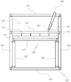
3 is a right side view of one embodiment of the multifunctional furniture of the present invention.
Figure 4 is an exploded view of a top support in accordance with an embodiment of the multifunctional furniture of the present invention.
5 is an exemplary view showing various embodiments of the top support of the multifunctional furniture of the present invention.
6 to 7 are exemplary views showing two embodiments and three embodiments of the multifunctional furniture of the present invention.
이하, 본 발명의 다기능 가구의 바람직한 실시 예에 따른 구성과 작용을 첨부 도면을 참고하여 더욱 상세히 설명하면 다음과 같다.DETAILED DESCRIPTION OF THE PREFERRED EMBODIMENTS The present invention will now be described more fully hereinafter with reference to the accompanying drawings, in which preferred embodiments of the invention are shown.
도 1은 본 발명의 다기능 가구의 1 실시 예에 따른 사시도, 도 2는 본 발명의 다기능 가구의 1 실시 예에 따른 분해 사시도, 도 3은 본 발명의 다기능 가구의 1 실시 예에 따른 우측면도, 도 4는 본 발명의 다기능 가구의 1 실시 예에 따른 상판지지부의 분해도, 도 5는 본 발명의 다기능 가구의 상판지지부의 다양한 실시 예를 도시한 예시도, 도 6 내지 도 7은 본 발명의 다기능 가구의 2 실시 예 및 3 실시 예를 도시한 예시도로서 함께 설명한다.FIG. 1 is a perspective view of a multifunctional furniture according to an embodiment of the present invention, FIG. 2 is an exploded perspective view of a multifunctional furniture according to an embodiment of the present invention, FIG. 3 is a right side view of a multifunctional furniture according to an embodiment of the present invention, FIG. 4 is an exploded view of a top support according to an embodiment of the present invention, FIG. 5 is an illustration showing various embodiments of the top support of the multifunctional furniture of the present invention, and FIGS. And two examples of furniture and three examples of furniture.
본 발명의 기술이 적용되는 다기능 가구(100)는 상판(110) 및 상판지지부(140)를 구성하는 세부 구성요소의 선택적인 조합에 의해 다양한 구조를 형성하도록 구성함으로써 필요에 따라 간편하게 다양한 형태 및 기능성을 구현할 수 있는 다기능 가구(100)에 관한 기술임을 주지한다.The
이를 위한 본 발명의 다기능 가구(100)는 도 1 내지 도 3에 도시한 바와 같이 상판(110)과, 상판(110)의 양측을 지지하는 상판지지부(140)를 기본 골격으로 형성하고 기능성에 따라서 등받이판(160)을 포함하도록 구성한다.1 to 3, the
상기 상판(110)은, 예컨대 본 발명의 다기능 가구(100)를 1 실시 예와 같은 의자 기능을 구현 시에는 착좌부의 기능을 수행하며, 본 발명의 2 실시 예 또는 3 실시 예와 같은 테이블 또는 침대 기능을 구현 시에는 테이블의 작업대 또는 침대 매트리스의 안착판과 같은 기능을 수행할 수 있도록 구비한다.The
상기 상판(110)의 크기는 후술하게 될 상판지지부(140)와 연계하여 다양하게 형성할 수 있으며 직사각형, 정사각형 등 다양한 형태로 형성할 수 있음은 물론이다.The size of the
또한, 상기 상판(110)의 하부에는 상판(110)에 평행하게 구비되는 보강판(112)을 결합하여 내구성 및 형태 유지성을 안정적으로 확보하도록 구성한다.In addition, a
아울러, 도 6에 도시한 바와 같이 상기 상판(110)의 하부에 상기 상판(110)에 수직하여 일정 높이로 구비되는 복수의 보강부재(111)를 결합하고 보강부재(111)의 단부에 보강판(112)을 결합하는 구성을 통해 내구성을 더욱 증진할 수 있으며, 이 경우 상판(110)과 보강판(112) 상간의 이격 공간은 소정의 수납공간으로 활용할 수도 있다.6, a plurality of reinforcing
상기 상판지지부(140)는 상판(110)의 하중을 지지하고 바닥에서부터의 높이를 설정하도록 마련된 수단이며 도 4 내지 도 5에 도시한 바와 같이 외부프레임(120)과 내부프레임(130)을 조립하여 구성한다.The upper
상기 외부프레임(120)은 각각 상호 대향하는 한 쌍으로 이루어진 상·하측 수평프레임(121,122)과 좌·우측 수직프레임(123,124)을 결합하여 골격을 형성하고 중심부에는 사각 형상의 개방부(125)를 구비한다.The
본 발명의 실시 예에서는 상기 상·하측 수평프레임(121,122)과 좌·우측 수직프레임(123,124) 간의 결합구조를 직각맞춤 방식에 의해 소정의 볼트를 체결하여 구현하였으나, 접합부의 횡단면을 45°로 절개하여 연귀맞춤 방식으로 결합하거나 또는 체결수단을 이용하지 않는 사개맞춤 방식을 적용하여 결합구조를 형성하는 것 역시 가능하다. 아울러, 필요에 따라 사용자가 수평프레임(121,122) 및 수직프레임(123,124)을 간편하게 분해 또는 조립 가능하도록 구성하는 것이 바람직할 것이다.In the embodiment of the present invention, the coupling structure between the upper and lower
상기 내부프레임(130)은 수평바(131)와, 수평바(131)의 양측 하부에서 상호 대향하도록 결합하는 한 쌍의 수직바(132,133)를 결합하여 형성한다. 내부프레임(130)의 수평바(131) 및 수직바(132,133) 역시 상술한 외부프레임(120)과 마찬가지로 다양한 결합구조를 적용할 수 있으며 필요에 따라 간편하게 분해 또는 조립 가능하도록 구성한다.The
따라서, 상기 외부프레임(120)의 개방부(125)의 내측에 상기 내부프레임(130)을 조립함으로써 상판지지부(140)를 형성한다.Accordingly, the upper
한편, 상기 상판지지부(140)는 복수를 구비하고 외부프레임(120)의 상측 수평프레임(121)과 내부프레임(130)의 수평바(131) 상간의 이격부 상에 상기 상판(110)의 양단을 인입하여 상판(110)과 조립하도록 구성한다.The upper
상기 개방부(125)의 깊이를 결정짓는 외부프레임(120) 및 내부프레임(130)을 구성하는 상·하측 수평프레임(121,122)과 좌·우측 수직프레임(123,124) 및 수평바(131)와 수직바(132,133)의 깊이는 다양한 범위에서 적용하여 상판지지부(140)가 상판(110)을 지지하는 용도 외에 예컨대 팔걸이, 사이드 테이블, 수납공간 등의 용도로도 활용할 수 있도록 구성하며, 상판(110)과의 조립 시 일반적인 가구에서 흔히 발생하는 틀어짐 또는 불안정한 지지상태가 초래되는 것을 배제할 수 있을 정도의 수준을 고려하여 최소 깊이를 형성함이 바람직하다.The upper and lower
아울러, 상기 외부프레임(120)의 상측 수평프레임(121)과 내부프레임(130)의 수평바(131) 상간의 이격부 상에 인입되는 상판(110) 단부의 인입 정도 역시 다양한 범위에서 적용할 수 있으며, 예컨대 도 1에 도시한 본 발명의 1 실시 예에서와같이 상판(110)의 양단이 내부프레임(130)의 중심부에 위치하도록 인입하여도 되나, 경우에 따라서는 상판(110)의 양단이 상기 이격부를 통과하여 내부프레임(130)이 상판(110)의 중심부에까지 위치하도록 인입할 수도 있으므로 다양한 구조 및 디자인을 도출할 수 있다.The degree of penetration of the end portion of the
또한, 도 5에 도시한 바와 같이 상기 내부프레임(130)의 수평바(131)는 상기 개방부(125)의 가로 폭(w)에 상응하는 길이(w')로 형성하고, 상기 내부프레임(130)의 높이(h')는 개방부(125)의 높이(h)보다 낮게 형성한다. 따라서 외부프레임(120)의 개방부(125)에 조립 시 좌·우측 수직프레임(123,124)의 내측면에 내부프레임(130)의 수직바(132,133)의 외측면이 당접하도록 조립함으로써 상호 간의 견고한 보강구조를 형성한다.5, the
한편, 상기 외부프레임(120) 및 내부프레임(130)은 각각 서로 다른 높이로 이루어진 다수를 구비하고, 상기 상판지지부(140)는, 상기 다수의 외부프레임(120) 및 내부프레임(130)을 상호 선택적인 조합에 따라 상이한 형상의 다수의 상판지지부(140)를 형성함으로써 상판지지부(140)를 취사선택하여 상판(110)과 조립하도록 구성한다.The
따라서, 상기 상판(110)의 양단에 조립되는 상판지지부(140)는 상호 동일한 한 쌍으로 구성하거나 또는 서로 다른 형상으로 구성할 수도 있으며, 서로 다른 형상 및 크기의 다수의 외부프레임(120) 및 내부프레임(130)의 다양한 조합에 의해 수많은 구조의 상판지지부(140)를 구성할 수 있으므로, 구조를 자유롭게 변경하여 목적하는 바의 기능성(종류) 및 디자인의 가구를 구현할 수 있다.Therefore, the upper
한편, 상기 상판(110)의 일측에는 상판(110)에 착탈 가능하도록 형성되는 착탈부재(150)를 장착하여 상판(110)에서 일정 각도 경사지게 구비되는 등받이판(160)을 조립한다.A
상기 착탈부재(150)는 상판(110)의 측면 형상에 상응하는 'ㄷ'자 형상의 절곡부(151)와, 상기 절곡부(151)의 상단에서 일정 각도 경사지게 구비되고 등받이판(160)의 하측에 형성된 장착공(161)에 상응하는 장착부(152)를 형성한다.The
상기 착탈부재(150)는 내구성이 우수한 금속 재질로 형성함이 바람직하나 소재를 굳이 제한할 필요는 없으며 그 밖에 절곡부(151)에 소정의 탄성을 부여하거나 등받이판(160)의 형상 및 재질을 다양하게 적용하여 사용성을 향상할 수도 있다.The
따라서, 상기 장착부(152)의 경사 각도에 상응하도록 경사지게 구비되는 등받이판(160)을 상판(110)에 결합하여 본 발명의 다기능 가구(100)를 의자로 사용 시 등받이 기능을 수행하도록 구성한다. 물론, 상기 등받이판(160)의 길이에 따라서 장착되는 착탈부재(150)의 수를 다양하게 적용할 수 있음은 당연하다 할 것이다.Accordingly, the
전술한 바와 같은 구성으로 이루어지는 본 발명의 기술이 적용된 다기능 가구(100)의 사용상태를 도 1에 도시한 바와 같은 1 실시 예, 또는 도 6 내지 도 7에 도시한 바와 같은 2 실시 예 및 3 실시 예를 참고하여 살펴보면 다음과 같다. 이하의 설명은 본 발명에 대하여 바람직한 실시 예를 들어 설명하는 것이므로 본 발명은 하기 실시 예에 의해 한정되는 것이 아니며 본 발명의 범주를 벗어나지 않는 범위 내에서 다양한 변형이 제공될 수 있음은 당연하다 할 것이다.The use state of the
본 발명의 다기능 가구(100)를 이용해 도 1에 도시한 1 실시 예와 같은 의자의 기능을 구현하기 위해서는, 우선 목적하는 바와 같은 크기의 상판(110)을 구비하고 상판(110)의 하부에는 보강판(112)을 결합한다.In order to realize the function of the chair as in the embodiment shown in FIG. 1 using the
상기 상판(110)을 일정 높이에 위치시켜 의자의 기본 구조를 형성하기 위하여 상판(110)의 양측에 조립할 복수의 상판지지부(140)를 구비한다.A plurality of upper
상기 상판지지부(140)는 상술한 바와 같이 외부프레임(120)과 내부프레임(130)의 조립으로 구성된다. 상기 외부프레임(120)과 내부프레임(130)은 도 5에 예시적으로 도시한 바와 같이 각각 서로 다른 높이로 이루어진 다수를 사전에 구비한다.The
우선, 상기 내부프레임(130)은 의자의 높이를 결정하므로 목적하는 바의 높이를 고려하여 선택한다. 예컨대 본 발명의 1 실시 예와 같이 양측에 한 쌍의 상판지지부(140)를 조립할 경우 내부프레임(130)은 서로 동일한 높이의 한 쌍을 선택함이 바람직하다.First, the
또한, 상기 내부프레임(130)이 인입되는 외부프레임(120)은 상기 선택한 내부프레임(130)의 높이보다 높은 개방부(125)를 형성하는 외부프레임(120) 중에서 디자인 또는 취향을 고려하여 취사선택한다. 본 발명의 1 실시 예와 같이 양측 한 쌍의 외부프레임(120)을 서로 다른 높이로 선택하는 것 역시 가능하므로 보다 감각적인 디자인의 가구로 구현할 수 있다.The
상기와 같이 선택된 외부프레임(120)의 개방부(125) 내측에 내부프레임(130)을 견고하게 조립하고, 외부프레임(120)과 내부프레임(130)의 높이 차에 의해 형성되는 수평프레임(121)과 수평바(131) 상간의 이격부 상에 상기 상판(110)의 양단을 인입한다.The
상기 개방부(125)의 가로 폭과 상판(110)의 측면부 폭이 상응하도록 구비하여 상판(110)과 상판지지부(140)의 양측에 유격이 없도록 조립하면 상판(110)과 상판지지부(140) 간에는 별도의 체결수단을 이용하지 않고서도 견고한 조립 상태를 구현할 수 있다.The
또한, 본 발명의 1 실시 예와 같이 등받이가 구비되는 의자 기능을 구현하기 위하여 상기 상판(110)의 일측에 등받이판(160)을 조립한다. 상기 등받이판(160)은 하측에 적어도 하나 이상의 장착공(161)을 일정 깊이로 형성하여 상판(110)의 수평면에 대해 일정 각도 경사지게 형성되는 착탈부재(150)의 장착부(152)를 장착공(161)에 장착하고 착탈부재(150)의 절곡부(151)를 상판(110)의 일측에 조립한다. Also, the
한편, 도 6에 도시한 바와 같이 본 발명의 다기능 가구(100)를 이용해 2 실시 예와 같은 테이블 또는 책상 기능을 구현하기 위해서는 우선 목적하는 바와 같은 크기의 상판(110)을 구비하고 상판(110)의 하부에는 보강판(112)을 결합한다. 아울러, 상기 상판(110)과 보강판(112) 상간에는 복수의 보강부재(111)를 결합하여 내구성 증진과 함께 소정의 수납공간으로서도 활용할 수 있도록 구비한다.6, in order to implement a table or a desk function using the
또한, 본 발명의 2 실시 예는 테이블 기능을 구현하므로 1 실시 예의 의자보다 높은 높이의 내부프레임(130)을 동일한 한 쌍으로 구비하는 복수의 상판지지부(140)를 마련하여 상술한 바와 같은 과정에 따라서 상기 상판(110)에 조립한다.In addition, since the second embodiment of the present invention realizes a table function, it is possible to provide a plurality of upper
아울러, 도 7에 도시한 바와 같이 본 발명의 다기능 가구(100)를 이용해 3 실시 예와 같은 침대 프레임의 기능을 구현하기 위해서는 상기 1 실시 예 및 2 실시 예와는 다른 크기의 상판(110) 및 상판지지부(140)를 이용하여 또 다른 구조의 가구를 구성하면 된다.7, in order to realize the function of the bed frame as in the third embodiment by using the
이상에서와 같은 본 발명에 따른 다기능 가구(100)는 상판(110) 및 상판지지부(140)를 구성하는 각 요소의 선택적인 조합에 의해 다양한 구조를 형성하도록 구성함으로써 설치환경 또는 취향, 디자인 등을 고려하여 필요에 따라 가구의 구조를 자유롭게 변경할 수 있는 이점이 있다. 그러므로, 상기 1 내지 3 실시 예에서 예시한 장의자, 테이블 또는 책상, 침대 프레임 이외에도 다양한 종류 및 구조로 이루어지는 가구를 간편하게 구현하는 것이 가능하므로 실용성과 기능성을 두루 갖춘 다기능 가구(100)를 제공할 수 있는 이점이 있다.The
100: 다기능 가구
110: 상판
111: 보강부재
112: 보강판
120: 외부프레임
121,122: 상·하측 수평프레임
123,124: 좌·우측 수직프레임
125: 개방부
130: 내부프레임
131: 수평바
132,133: 수직바
140: 상판지지부
150: 착탈부재
151: 절곡부
152: 장착부
160: 등받이판
161: 장착공100: Multifunctional furniture
110: top plate
111: reinforcing member
112: reinforcing plate
120: outer frame
121, 122: upper and lower horizontal frames
123,124: Left and right vertical frames
125:
130: inner frame
131: Horizontal bar
132, 133: vertical bar
140: top plate support
150:
151:
152:
160: Backrest plate
161: Mounting ball
Claims (5)
각각 상호 대향하는 한 쌍으로 이루어진 상·하측 수평프레임(121,122)과 좌·우측 수직프레임(123,124)을 결합하여 골격을 형성하고 중심부에는 사각 형상의 개방부(125)를 구비하는 외부프레임(120)과;
수평바(131)와, 수평바(131)의 양측 하부에서 상호 대향하도록 결합하는 한 쌍의 수직바(132,133)를 결합하여 형성하는 내부프레임(130)을 포함하여 이루어지고;
상기 외부프레임(120)의 개방부(125)의 내측에는 상기 내부프레임(130)을 조립하여 상판지지부(140)를 형성하고;
상기 상판지지부(140)는 복수를 구비하고 상측 수평프레임(121)과 수평바(131) 상간의 이격부 상에 상기 상판(110)의 양단을 인입하여 상판(110)과 조립하도록 구성하는 것을 특징으로 하는 다기능 가구.An upper plate 110;
An outer frame 120 having a skeleton formed by a pair of upper and lower horizontal frames 121 and 122 and a pair of left and right vertical frames 123 and 124 and a rectangular opening 125 at the center, and;
A horizontal bar 131 and an inner frame 130 formed by combining a pair of vertical bars 132 and 133 which are mutually opposed to each other at both lower sides of the horizontal bar 131;
The inner frame 130 is assembled to the inside of the opening 125 of the outer frame 120 to form an upper plate supporting part 140;
The upper plate supporting part 140 is provided with a plurality of parts and is configured to pull both ends of the upper plate 110 on the spacing part between the upper horizontal frame 121 and the horizontal bars 131 to be assembled with the upper plate 110 Multifunctional furniture.
상기 내부프레임(130)의 수평바(131)는 상기 개방부(125)의 가로 폭(w)에 상응하는 길이(w')로 형성하고, 상기 내부프레임(130)의 높이(h')는 개방부(125)의 높이(h)보다 낮게 형성하도록 구성하는 것을 특징으로 하는 다기능 가구.The method according to claim 1,
The horizontal bar 131 of the inner frame 130 has a length w 'corresponding to the width w of the opening 125 and the height h' of the inner frame 130 is Is smaller than the height (h) of the opening (125).
상기 외부프레임(120) 및 내부프레임(130)은, 각각 서로 다른 높이로 이루어진 다수를 구비하고;
상기 상판지지부(140)는, 상기 다수의 외부프레임(120) 및 내부프레임(130)을 상호 선택적인 조합에 따라 상이한 형상의 다수의 상판지지부(140)를 형성함으로써 상판지지부(140)를 취사선택하여 상판(110)과 조립하도록 구성하는 것을 특징으로 하는 다기능 가구.3. The method according to claim 1 or 2,
The outer frame 120 and the inner frame 130 have a plurality of different heights, respectively;
The upper plate supporting part 140 may include a plurality of upper plate supporting parts 140 having different shapes according to a combination of the plurality of outer frames 120 and the inner frame 130, So as to be assembled with the upper plate (110).
상기 상판(110)의 하부에는, 상판(110)에 수직하여 일정 높이로 구비되는 복수의 보강부재(111)를 결합하고, 상판(110)에 평행하게 구비되는 보강판(112)을 보강부재(111)의 단부에 결합하여 구성하는 것을 특징으로 하는 다기능 가구.The method according to claim 1,
A plurality of reinforcing members 111 provided at a predetermined height perpendicular to the upper plate 110 are coupled to a lower portion of the upper plate 110 and a reinforcing plate 112 provided parallel to the upper plate 110 is connected to a reinforcing member 111). ≪ / RTI >
상기 상판(110)의 일측에는, 상판(110)에 착탈 가능하도록 형성되는 착탈부재(150)를 장착하여 상판(110)에서 일정 각도 경사지게 구비되는 등받이판(160)을 조립하고;
상기 착탈부재(150)는, 상판(110)의 측면 형상에 상응하는 'ㄷ'자 형상의 절곡부(151)와, 상기 절곡부(151)의 상단에서 일정 각도 경사지게 구비되고 등받이판(160)의 하측에 형성된 장착공(161)에 상응하는 장착부(152)를 형성하도록 구성하는 것을 특징으로 하는 다기능 가구.The method according to claim 1,
A detachable member 150 detachable from the upper plate 110 is mounted on one side of the upper plate 110 to assemble a backrest plate 160 inclined at a predetermined angle from the upper plate 110;
The detachable member 150 includes a bent portion 151 having a U shape corresponding to a side surface shape of the upper plate 110 and a backrest plate 160 provided at an angle to the upper end of the bent portion 151, And a mounting portion (152) corresponding to the mounting hole (161) formed on the lower side of the mounting hole (161).
Priority Applications (1)
| Application Number | Priority Date | Filing Date | Title |
|---|---|---|---|
| KR1020160114257A KR20180027097A (en) | 2016-09-06 | 2016-09-06 | Multifunctional furniture |
Applications Claiming Priority (1)
| Application Number | Priority Date | Filing Date | Title |
|---|---|---|---|
| KR1020160114257A KR20180027097A (en) | 2016-09-06 | 2016-09-06 | Multifunctional furniture |
Publications (1)
| Publication Number | Publication Date |
|---|---|
| KR20180027097A true KR20180027097A (en) | 2018-03-14 |
Family
ID=61660262
Family Applications (1)
| Application Number | Title | Priority Date | Filing Date |
|---|---|---|---|
| KR1020160114257A Ceased KR20180027097A (en) | 2016-09-06 | 2016-09-06 | Multifunctional furniture |
Country Status (1)
| Country | Link |
|---|---|
| KR (1) | KR20180027097A (en) |
Cited By (3)
| Publication number | Priority date | Publication date | Assignee | Title |
|---|---|---|---|---|
| CN108552833A (en) * | 2018-04-24 | 2018-09-21 | 江门市江海区颖轩投资咨询有限公司 | A kind of sofa armchair structure |
| CN110916388A (en) * | 2020-01-02 | 2020-03-27 | 广东工业大学 | Multifunctional furniture |
| US11653767B1 (en) * | 2021-05-11 | 2023-05-23 | Lee Michael Jackson | Seatback assembly attachable to a wall |
-
2016
- 2016-09-06 KR KR1020160114257A patent/KR20180027097A/en not_active Ceased
Cited By (3)
| Publication number | Priority date | Publication date | Assignee | Title |
|---|---|---|---|---|
| CN108552833A (en) * | 2018-04-24 | 2018-09-21 | 江门市江海区颖轩投资咨询有限公司 | A kind of sofa armchair structure |
| CN110916388A (en) * | 2020-01-02 | 2020-03-27 | 广东工业大学 | Multifunctional furniture |
| US11653767B1 (en) * | 2021-05-11 | 2023-05-23 | Lee Michael Jackson | Seatback assembly attachable to a wall |
Similar Documents
| Publication | Publication Date | Title |
|---|---|---|
| US6824220B1 (en) | Modular furniture retaining system | |
| AU2010235388B2 (en) | Portable assembly-type flat bench | |
| KR102154696B1 (en) | Seat assembly and chair having the same | |
| US9370244B1 (en) | Multi-functional, reconfigurable furniture system for use on uneven surfaces | |
| KR20130040487A (en) | An integral dest and chair for two | |
| KR101136977B1 (en) | Prefabricated furniture having various uses | |
| KR20150002434U (en) | A Fabricated Table Using Mortise Joint | |
| CA2940479C (en) | Slidable furniture with in-wall mounting system | |
| JP3685022B2 (en) | Desk with panel | |
| JP2009125095A (en) | Furniture unit and free configuration type furniture using the same | |
| JP5288604B2 (en) | System kitchen | |
| KR100809099B1 (en) | desk | |
| KR200475666Y1 (en) | A sectional chair | |
| JP2023174440A (en) | Connectable frame, system kitchen, kitchen table and dining table | |
| KR200475787Y1 (en) | Support for Assembly Type Furniture and Assembly Type Furniture Using The Same | |
| JP6456626B2 (en) | Desk system | |
| US20020153813A1 (en) | Modular furniture construction system | |
| KR200324319Y1 (en) | A support frame of a sectional furniture | |
| JP3241992U (en) | Easy assembly table | |
| JP4470750B2 (en) | Learning furniture | |
| CN209983837U (en) | An assembled multifunctional furniture | |
| KR101562797B1 (en) | Kit for furniture | |
| CN211582249U (en) | Multifunctional furniture | |
| KR102830201B1 (en) | height-adjustable structure for a table or chair | |
| JP3237803U (en) | Ready-to-assemble furniture with legs |
Legal Events
| Date | Code | Title | Description |
|---|---|---|---|
| A201 | Request for examination | ||
| PA0109 | Patent application |
Patent event code: PA01091R01D Comment text: Patent Application Patent event date: 20160906 |
|
| PA0201 | Request for examination | ||
| PG1501 | Laying open of application | ||
| E902 | Notification of reason for refusal | ||
| PE0902 | Notice of grounds for rejection |
Comment text: Notification of reason for refusal Patent event date: 20180417 Patent event code: PE09021S01D |
|
| E601 | Decision to refuse application | ||
| PE0601 | Decision on rejection of patent |
Patent event date: 20181026 Comment text: Decision to Refuse Application Patent event code: PE06012S01D Patent event date: 20180417 Comment text: Notification of reason for refusal Patent event code: PE06011S01I |