JP3681139B2 - Two-dimensional adjustment door - Google Patents
Two-dimensional adjustment door Download PDFInfo
- Publication number
- JP3681139B2 JP3681139B2 JP01025997A JP1025997A JP3681139B2 JP 3681139 B2 JP3681139 B2 JP 3681139B2 JP 01025997 A JP01025997 A JP 01025997A JP 1025997 A JP1025997 A JP 1025997A JP 3681139 B2 JP3681139 B2 JP 3681139B2
- Authority
- JP
- Japan
- Prior art keywords
- indoor
- door
- adjustment
- outdoor
- outer case
- Prior art date
- Legal status (The legal status is an assumption and is not a legal conclusion. Google has not performed a legal analysis and makes no representation as to the accuracy of the status listed.)
- Expired - Fee Related
Links
Images


Description
【0001】
【発明の属する技術分野】
本発明は、たとえば引違い障子等において、障子を円滑に開閉できるように、上下方向調整機構および室内外方向調整機構を同時に兼ね備えた二次元調整戸車に関する。
【0002】
【従来の技術】
従来より、片引き・引き違い形式の戸または障子等に対しては、開閉時の滑り抵抗を軽減し開閉操作を円滑化するために、その下端面に対して戸車が設けられている。
かかる戸車に関しては、従来より建付け後に戸または障子等を上下方向に調整し得るようにしたものが提案されている。
その一例を紹介すると、図32に示されるように、ローラ50を内枠51と外枠52とからなる保持枠53により保持し、前記外枠52から貫通状態で設けられた上下方向調整ネジ54を前記内枠51に対して螺合させ、この上下方向調整ネジ54を回して内枠51をレール方向にスライドさせることにより、戸または障子を上下方向に調整可能としている。具体的には、前記内枠51にローラ50のローラ軸50aを保持するための斜め方向溝51aを形成するとともに、外枠52にローラ軸50aを保持する鉛直方向溝52aを形成し、前記ローラ50を前記内枠51に装着した状態で外枠52を嵌め込むことにより、これら両溝51a、52aの交差部によってローラ軸50aを保持するように構成し、前記上下方向調整ネジ54を回して前記内枠51をレール方向にスライドさせると、内枠51の斜め方向溝51aにガイドされてローラ50が上下方向に移動し、相対的に障子または戸全体が上下方向に移動調整可能となっている。
【0003】
【発明が解決しようとする課題】
すなわち、従来より提供されている戸車は、前述のように鴨居等に対する係合具合を調整するため、上下方向には調整可能となっているものの、戸または障子等の建付け、建込み時の調整不具合や、経時的に生ずる障子自体の反り・変形等により、内障子と外障子との召合せ部等が接触したり、衝突したりする不具合が生じたとしても、室内外方向の調整は一切できない構造となっている。
【0004】
そこで、本発明の主たる課題は、召合せ部等の接触・衝突を無くして障子または戸を円滑に開閉し得るように、室内外方向にも位置調整可能とした二次元調整戸車を提供することにある。
【0005】
【課題を解決するための手段】
前記課題を解決するために本発明は、外ケース内に収容された、ローラおよびその保持枠からなる戸車本体が、略上下方向に沿う方向に位置調整可能に支持されているとともに、前記外ケース内において前記室内外方向にスライド用間隙を有する状態で収容され室内外方向にも位置調整可能に支持された二次元調整戸車であって、
前記戸車本体の保持枠を貫いて外ケースの側壁間に横架された室内外方向配置の支軸によって前記戸車本体を回動可能に支持するとともに、前記保持枠の背面壁に対して直接または間接的に先端が当接する上下方向調整ネジを設け、この上下方向調整ネジの前後進調整に伴う前記戸車本体の回動位置調整により前記戸車本体を略上下方向に位置調整可能とし、
前記支軸に対して、前記戸車本体と係合して一体的にスライド動作するとともに、縦方向の長孔溝を有する作動ブロック片を設ける一方、レール方向の回転中心軸をもって回転自在とされる室内外方向調整部材を設け、この室内外方向調整部材の作動ブロック片側の面に前記回転中心軸から偏心した位置に前記作動ブロック片の縦方向長孔溝に係合する偏心突起を設け、前記室内外方向調整部材の回転調整により前記作動ブロック片を支軸方向にスライドさせ、前記戸車本体を室内外方向に位置調整可能としたことを特徴とするものである。
【0006】
この場合に、前記室内外方向調整部材は本体部分の周面に正多角形状部を有し、両側に配された弾発部材が前記正多角形状部の両側面へ夫々押圧接触することにより前記室内外方向調整部材の固定保持を行うようにするのが望ましい。また、前記弾発部材は、前記外ケースの側壁に離間を空けて一対の縦方向スリットを形成するとともに、これら両縦方向スリットに挟まれた離間部の上下端の一方を縁切りすることにより形成した片持ち梁状の弾発片とすることができる。
【0007】
また、前記室内外方向調整部材と外ケースとの当接接触面部において、一方の側に噛合爪を形成するとともに、他方の側に周方向に亘って前記噛合爪が係合する噛合爪受け部を形成し、かつ前記室内外方向調整部材を戸車本体側付勢して設けてある構造とすることもできる。
【0008】
一方、前記作動ブロック片から延在して前記保持枠の一部に係止し、戸車本体を外ケース内に収容保持する係止用舌片を形成することにより、建て付け時に戸車本体が垂れ下がるのを防止できるため建て付け作業が容易となる。また、前記保持枠の背面壁と上下方向調整ネジ先端との間に、下端側の室内外方向回動軸をもって回動自在とされる保持枠押え板を介在させることにより、保持枠を偏圧することなく均一に押圧保持できるようになる。
【0009】
本発明においては、戸または障子等の建付け、建込み時に内・外の戸・障子等の召合せ部が接触したり、または衝突する場合などは、ドライバーなどの手工具類により、前記室内外方向調整部材を回転させることにより、戸車本体を室内外方向に位置調整できるため、かかる不具合を簡単に修正することができる。また、経時変化により、その後に戸または障子等に反りや変形が生じ、障子同士が接触するようになった場合でも、居住者が簡単にこれを修正することができる。
【0010】
【発明の実施の形態】
以下、本発明の実施の形態を図面に基づいて詳述する。
〔第1実施形態例〕
図1は本発明に係る二次元調整戸車1の側面図、図2は図1のII−II線矢視図、図3は図1のIII −III 線矢視図、図4は分解図、図5は組立後の縦断面図である。
本発明に係る二次元調整戸車(以下、単に調整戸車という。)1は、主に外ケース2と、ローラ5およびローラ保持枠4からなる戸車本体3と、前記戸車本体3を外ケース2に対して回動可能に支持する支軸9と、前記ローラ保持枠4の背面壁に対して先端が当接するように配置され、前後進調整により戸車本体3の上下方向調整を行うための上下方向調整ネジ8と、前記戸車本体3と係合しながら前記支軸9に挿通支持され戸車本体3と共に室内外方向にスライド動作する作動ブロック片6と、この作動ブロック片6を室内外方向にスライド移動させるための室内外方向調整部材7とにより構成される。
【0011】
前記外ケース2は、詳細には図6〜図9に示されるように、ポリアミド等の樹脂により製造された型成形品であり、下側に開口する戸車本体3収容のための内空部2aを有し、障子の側端面側(以下、障子端側という。)の側壁部に上下方向調整ネジ8の設置部、および室内外方向調整部材7の設置部を有する。また、室内外方向に対面する両側壁には戸車本体3を回動支持する支軸9のための保持孔19、19が形成され、障子端側の上部および他端側の下面には障子への取付けのためにビス孔を有する突出片11、12が形成されている。
【0012】
さらに詳述すると、外ケース2の障子端側の側壁上部位置には上下方向調整ネジ8の取付け孔13(以下、ネジ取付け孔という。)と、前記上下方向調整ネジ8に螺合されるナット10のためのナット嵌設孔14とが水平方向に連続して形成されている。具体的には、前記ネジ取付け孔13は側方に開口するやや大径のネジ頭部孔13aと、このネジ頭部孔13aの底壁に形成されたネジ軸孔13bとからなり、前記ネジ軸孔13bの中間位置に側方に開口するナット10の嵌設孔14が形成されており、図4に示されるように、前記ナット嵌設孔14にナット10を装設した状態で上下方向調整ネジ8を螺入することにより設置する。また、上下方向調整ネジ8の先端部相当位置には側方に開口する窓16が形成されており、前記上下方向調整ネジ8を螺設した後、前記窓16からペンチ等を挿入して上下方向調整ネジ8のネジ山を潰すことにより抜け止め処理が行えるようにしてある。
【0013】
また、前記ネジ取付け孔13の下方位置には、室内外方向調整部材7の取付け孔17(以下、カム取付け孔という。)が形成されているとともに、このカム取付け孔17の隣接位置には側壁に離間を空けて一対の縦方向スリットを形成するとともに、これら両縦方向スリットに挟まれた離間部の上下端の一方、本例では上端を縁切りすることにより、側壁のそれぞれに片持ち梁状の弾発片18、18が形成されている。
【0014】
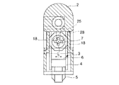
一方、前記室内外方向調整部材7は、図4、図14および図15に示されるように、外ケース2の前記カム取付け孔17に対して嵌合する嵌合頭部26と、外ケース2の弾発片18、18と接触係合する六角形状部27と、回転中心軸Lから距離Sだけ偏心した位置に設けられた偏心突起28とから構成されており、前記嵌合頭部26が前記カム取付け孔17に嵌合した状態で取り付けられる。そして、図16に示されるように、前記外ケース2の弾発片18、18が前記六角形状部27の両側面に夫々に押圧接触することにより、室内外方向調整部材7が45°回転毎に固定保持されるようになっている。
【0015】
次いで、前記戸車本体3は、図10および図11に示されるように、ローラ5と、このローラ5を回転軸21により回転自在に支持するローラ保持枠4とからなる。前記ローラ保持枠4は、金属板の成形により略断面コ字状に加工された部材であり、前記回転軸21の対辺側上部には、ローラ保持枠4の上面端から延在して垂下する突出片4cにより上下方向調整ネジ8の先端が当接するやや変断面形状の背面壁29(本明細書では、戸車本体3が外ケース2から突出する回転方向を正方向と考えているため、その反対面側を背面側としている。)が形成されている。また、その下方側には対峙する両壁面の一部が膨出して突出部4aが形成され、該突出部4aに支軸9が挿通するための通孔4bが形成されている。
【0016】
また、前記突出部4aの上部位置には、両壁面から延在して左右一対の受け係止片4d、4dが設けられ、後述の作動ブロック片6の係止用舌片24が係止することにより、障子への組付け状態で前記戸車本体3が下方向に垂れ下がらないように保持するようになっている。
【0017】
一方、作動ブロック片6は図12および図13に示されるように、ブロック本体23と、このブロック本体23下面よりU字状に延在する係止用舌片24とからなり、前記ブロック本体23には水平方向に貫通する支軸9が挿通される通孔23aが形成されているとともに、背面側上部には縦方向に長い長孔溝25が形成されている。
【0018】
外ケース2に対する組み込みは、図4に示されるように、作動ブロック片6を前記戸車本体3の一対の突出部4a、4aの間に装入し、ローラ保持枠4の通孔4bと作動ブロック片6の通孔23aとを連続させた状態としたまま、これら戸車本体3と作動ブロック片6とを外ケース2の内空部2aに装入し、外ケース2の側部から支軸9を前記通孔4b、通孔23aを通して挿通し、対壁面側で先端をカシメて固定する。組み込み状態では、戸車本体3は、図3に示されるように、外ケース2との間にスライド用間隙H1 、H2 を有する状態で外ケース2内に収容され、外ケース2内に横架される前記支軸9をスライド軸として室内外方向に移動自在となっている。また、図5にも示されるように、作動ブロック片6の長孔溝25に前記室内外方向調整部材7の偏心突起28が嵌入するとともに、作動ブロック片6の係止用舌片24の先端が前記ローラ保持枠4の受け係止片4d、4dに対して係止し戸車本体3が垂れ下がらないように保持している。
【0019】
かかる調整戸車1を障子下面の凹部に装着した状態で、障子の上下方向調整を行う場合には、上下方向調整ネジ8をネジ回し等の工具を用いて左右方向の一方に回転させて戸車本体3の上下方向位置を調整する。前記上下方向調整ネジ8は位置固定のナット10に螺入されてあり、前記上下方向調整ネジ8を右方向に回転させると、上下方向調整ネジ8は螺進し戸車本体3の背面壁29を押し、戸車本体3を支軸9回りに回転させる。図1に示すように、戸車本体3が下方に下がれば相対的に障子が上方に移動する。また、前記上下方向調整ネジ8を左方向に回転させると、逆に戸車本体3が外ケース2内に潜り込むように回動するため障子が下方に移動される。
【0020】
また、室内外方向調整を行う場合には、室内外方向調整部材7を左右方向の一方に回転させて行う。図16に示されるように、作動ブロック片6の長孔溝25に対して室内外方向調整部材7の偏心突起28が嵌入状態にあり、室内外方向調整部材7を回転させると、前記偏心突起28が室内外方向調整部材7の中心軸L回りに移動する。この偏心突起28の移動に伴って作動ブロック片6が室内外方向に移動されるとともに、この作動ブロック片6と一体的にスライド動作するように係合された戸車本体3が室内外方向に移動される。室内外方向の調整可能量は、偏心突起28の偏心量Sに相当し、±Sの距離の調整が可能である。前記室内外方向調整部材7は、外ケース2の弾発片18との接触部形状を正六角形としてあるため、調整段階は+S、+1/2S、0、−1/2S、−Sの5段階となるが、もう少し微妙な調整を可能としたいならば、図17に示されるように、弾発片18に接触する部分を正12角形状とした室内外方向調整部材7’とすることもできる。この場合には30°回転時毎に弾発片18によって固定保持されるようになるため、7段階の調整が可能となる。
【0021】
なお、外ケース2の障子端側には、図2にも示されるように、上下方向調整の調整方向表示、および室内外方向調整の調整方向表示が刻印されており調整方向を間違えずに行えるようにしてあり、調整後には見栄えのためにキャップ20が設けられるようになっている。
【0022】
ところで、障子または戸が嵌め込まれる鴨居等の上枠においては、室内外方向に障子または戸が移動されることに伴い、レールを室内外方向に移動調整可能としている。具体的には、図18に示されるように、鴨居30に対してビス31により取り付けられるレール32のビス孔32aを室内外方向の所謂バカ孔としておき、レール32を室内外方向に移動調整できるようにしている。また、図19に示されるように、ビス配設部位にU字状切欠きを有する左右一対のレール半割部材33A、33Bを用い、これらレール半割部材33A、33Bの位置をそれぞれ調整した後、ビス31により固定することでもよい。
【0023】
〔第2実施形態例〕
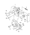
図20は本発明の第2例に係る二次元調整戸車1’の側面図、図21は図20のA−A線矢視図、図22は図20のB−B線矢視図、図23は分解図、図24は組立後の縦断面図である。以下、第1例と同一機能のものについては前記第1例と同じ符号を付し説明は省略する。
本第2例に係る調整戸車1’は、主に外ケース2と、ローラ5およびローラ保持枠4からなる戸車本体3と、前記戸車本体3を外ケース2に対して回動可能に支持する支軸9と、前記ローラ保持枠4の背面壁に対して先端が当接するように配置され、前後進調整により戸車本体3の上下方向調整を行うための上下方向調整ネジ8と、前記戸車本体3と係合しながら前記支軸9に挿通支持され戸車本体3と共に室内外方向にスライド動作する作動ブロック片34と、この作動ブロック片34を室内外方向にスライド移動させるための室内外方向調整部材35と、前記ローラ保持枠4の背面壁と上下方向調整ネジ8先端との間に、下端側の室内外方向回動軸をもって回動自在とされる保持枠押え板36とにより構成される。
【0024】
基本的構成は前記第1例と同じであるが、第1例と異符号を付した部材、具体的には作動ブロック片34、室内外方向調整部材35に対して若干の変更を加えてあり、新たに保持枠押え板36を設けた点が異なる。
【0025】
以下、第1例と異なる構成部分を中心に詳述する。
前記作動ブロック片34は、詳細には図28および図29に示されるように、ブロック本体が面スリット34cによって、木口側から見て前部ブロック34Bと後部ブロック34Aとに分割され、ブロック本体の下部には支軸9が挿通される通孔34aが形成されている。また、ブロック本体の下部前側から1/4円弧状にローラ保持枠4に係止して外ケース2内に収容保持するための係止用舌片34Cが形成されているとともに、前記後部ブロック34Aの木口面側(背面側)には偏心突起28が係合する縦方向長孔溝25が形成されている。
【0026】
一方、前記室内外方向調整部材35は、図30および図31に示されるように、外ケース2のカム取付け孔17に対して嵌合する嵌合軸部35Aと、ネジ回し用溝孔が形成された操作部35Bと、回転中心軸Lから距離Sだけ偏心した位置に設けられた偏心突起28と、前記作動ブロック片34の前部ブロック34Bが係合して、該室内外方向調整部材35全体を戸車本体3側に付勢するための受け係合片35Cとから構成されている。また、前記操作部35Bの戸車本体3側の面には、左右一対の噛合爪35a、35aが形成されている。
【0027】
他方で、外ケース2における前記室内外調整部材35の取付け部には、図25および図26に示されるように、カム取付け孔17の木口側周囲に対して、周方向に沿って多数の噛合爪受け部17a,17a…が形成されており、前記室内外調整部材35の噛合爪35a、35aが係合するようになっている。
【0028】
組立は、図23に示されるように、室内外方向調整部材35をカム取付け孔17部に装着する一方、作動ブロック片34を前記戸車本体3の一対の突出部4a、4aの間に装入し、ローラ保持枠4の通孔4bと作動ブロック片34の通孔34aとを連続させた状態のまま、これら戸車本体3と作動ブロック片34とを外ケース2の内空部に装入し、外ケース2の側部から支軸9を前記通孔4b、通孔34aを通して挿通し、対壁面側で先端をカシメて固定する。組み込み状態では、図24に示されるように、作動ブロック片34の面スリット34cの間に室内外方向調整部材35の受け係合片35Cが挿入位置し、作動ブロック片34の前部ブロック34Bの弾性力によって室内外方向調整部材35全体が戸車本体3側に付勢されている。また、作動ブロック片34の縦方向長孔溝25に対して室内外方向調整部材35の偏心突起28が嵌入し、作動ブロック片34の係止用舌片34Cの先端幅広部34dがローラ保持枠4の下面側に係止し、戸車本体3が垂れ下がらないように外ケース2内に収容保持されている。
【0029】
したがって、室内外方向調整部材35を左右方向の一方に回転させると、前記偏心突起28が室内外方向調整部材35の中心軸L回りに移動する。この偏心突起28の移動に伴って作動ブロック片34が室内外方向に移動されるとともに、この作動ブロック片34と一体的にスライド動作するように係合された戸車本体3が室内外方向に移動される。
【0030】
他方で、本第2例においては、前記ローラ保持枠4の背面壁と上下方向調整ネジ8先端との間に、下端側の室内外方向回動軸をもって回動自在とされる保持枠押え板36を介在させている。前記保持枠押え板36は、図23に示されるように、方形板36aの一側がわ両端部に突起軸36b、36bを備えたもので、取付けは外ケース2の側面に形成された装入孔2bより外ケース2内に装入する。前記保持枠押え板36の設置状態時には、前記装入孔2bの端部に形成された軸保持部2c、2cに対して保持枠押え板36の突起軸36b、36bが係合し、前記突起軸36b、36bを回転中心軸として回動するようになっている。したがって、図27に示されるように、上下方向調整時に、上下方向調整ネジ8を螺入させて戸車本体3を下方向に回動させた際には、共に回動してローラ保持枠4の背面を均一に押圧する。
【0031】
なお、本第2例において、前記上下方向調整ネジ8は、第1例のようにナット部材10を用いることなく外ケース2の本体に形成された雌ネジ孔2dに対して直接螺入されている。
【0032】
【発明の効果】
以上詳説のとおり、本発明に係る調整戸車によれば、戸または障子を室内外方向にも移動調整できるため、召合せ部等の接触・衝突を無くして、常に障子または戸を円滑に開閉し得る状態に維持できる。
【図面の簡単な説明】
【図1】 本発明の第1例に係る調整戸車1の側面図である。
【図2】 図1のII−II線矢視図である。
【図3】 図1のIII −III 線矢視図である。
【図4】 分解図である。
【図5】 組立後の縦断面図である。
【図6】 外ケース2の側面図である。
【図7】 外ケース2の縦断面図である。
【図8】 図6のVIII−VIII線矢視図である。
【図9】 図6のIX−IX線矢視図である。
【図10】 戸車本体3の側面図である。
【図11】 戸車本体3の正面図である。
【図12】 作動ブロック片6の側面図である。
【図13】 作動ブロック片6の背面図である。
【図14】 室内外方向調整部材7の正面図である。
【図15】 室内外方向調整部材7の平面図である。
【図16】 室内外方向調整部材7の作動状態説明図である。
【図17】 他の室内外方向調整部材例の正面図である。
【図18】 本発明調整戸車に対応した鴨居用レールの断面図である。
【図19】 本発明調整戸車に対応した鴨居用レールの断面図である。
【図20】 本発明の第2例に係る調整戸車1’の側面図である。
【図21】 図20のA−A線矢視図である。
【図22】 図20のB−B線矢視図である。
【図23】 分解図である。
【図24】 組立後の縦断面図である。
【図25】 外ケース2の正面図である。
【図26】 カム取付け孔17部の縦断面図である。
【図27】 戸車本体3の回動操作状態図である。
【図28】 作動ブロック片34の側面図である。
【図29】 作動ブロック片34の正面図である。
【図30】 室内外方向調整部材35の平面図である。
【図31】 室内外方向調整部材35の側面図である。
【図32】 従来の戸車の側面図である。
【符号の説明】
1・1’…調整戸車、2…外ケース、3…戸車本体、4…ローラ保持枠、5…ローラ、6・34…作動ブロック片、7・35…室内外方向調整部材、8…上下方向調整ネジ、9…支軸、10…ナット、18…弾発片、24・34C…係止用舌片、25…長孔溝、27…正六角形状部、28…偏心突起、36…保持枠押え板。 [0001]
BACKGROUND OF THE INVENTION
The present invention relates to a two-dimensional adjustment door wheel that simultaneously has an up-down direction adjusting mechanism and an indoor / outdoor direction adjusting mechanism so that the shoji can be opened and closed smoothly, for example, in a sliding shoji.
[0002]
[Prior art]
2. Description of the Related Art Conventionally, with respect to a one-pull / pull-type door or a shoji door, a door wheel is provided on the lower end surface of the door in order to reduce sliding resistance during opening and closing and to facilitate opening and closing operations.
With regard to such a door cart, there has been conventionally proposed a door or a shoji that can be adjusted in the vertical direction after being installed.
As an example, as shown in FIG. 32, the
[0003]
[Problems to be solved by the invention]
In other words, the doorcars provided in the past are adjustable in the vertical direction in order to adjust the degree of engagement with the duck and the like as described above, but at the time of building or installing doors or shojis, etc. Even if there is a problem that the summoning part of the inner and outer shoji comes into contact with or collides with each other due to adjustment problems or the warping / deformation of the shoji itself that occurs over time, the adjustment in the indoor / outdoor direction is possible. The structure is not possible at all.
[0004]
Thus, the main problem of the present invention is to provide a two-dimensional adjustment door that can be adjusted in the indoor and outdoor directions so that the shoji or door can be opened and closed smoothly without contact / collision of the summoning section or the like. It is in.
[0005]
[Means for Solving the Problems]
In order to solve the above-mentioned problems, the present invention provides a door wheel main body, which is housed in an outer case and is composed of a roller and a holding frame thereof, and is supported so that the position thereof can be adjusted in a direction substantially along the vertical direction. A two-dimensional adjustment door wheel accommodated in a state having a sliding gap in the indoor / outdoor direction and supported so as to be position adjustable in the indoor / outdoor direction,
The door frame body is rotatably supported by a support shaft arranged in an indoor / outdoor direction that extends horizontally between the side walls of the outer case through the holding frame of the door frame body, and directly or against the rear wall of the holding frame. A vertical adjustment screw that indirectly contacts the tip is provided, and the position of the door body can be adjusted substantially vertically by adjusting the rotational position of the door body when the vertical adjustment screw is moved forward and backward.
The operation shaft piece having a long slot in the vertical direction is provided on the support shaft and engaged with the door main body to slide integrally with the support shaft. On the other hand, the support shaft is rotatable with a rotation center axis in the rail direction. An indoor / outdoor direction adjustment member is provided, and an eccentric protrusion that engages with a longitudinal slot in the operation block piece is provided on a surface of the operation block piece side of the indoor / outdoor direction adjustment member at a position eccentric from the rotation center axis, The operation block piece is slid in the support shaft direction by adjusting the rotation of the indoor / outdoor direction adjusting member, and the position of the door pulley body can be adjusted in the indoor / outdoor direction.
[0006]
In this case, the indoor / outdoor direction adjustment member has a regular polygonal shape portion on the peripheral surface of the main body portion, and the elastic members arranged on both sides press and contact the both side surfaces of the regular polygonal shape portion, respectively. It is desirable to fix and hold the indoor / outdoor direction adjusting member. In addition, the elastic member is formed by forming a pair of vertical slits in the side wall of the outer case so as to be spaced apart, and cutting one of the upper and lower ends of the separation portion sandwiched between the two vertical slits. Cantilevered bullet pieces.
[0007]
Further, in the contact contact surface portion between the indoor / outdoor direction adjusting member and the outer case, a meshing claw receiving portion in which a meshing claw is formed on one side and the meshing claw is engaged with the other side in the circumferential direction. And the indoor / outdoor direction adjusting member may be biased and provided on the door body side.
[0008]
On the other hand, by extending the operating block piece and locking it to a part of the holding frame, and forming a locking tongue piece for holding and holding the door car body in the outer case, the door wheel body hangs down during installation. This makes it easy to build. In addition, a holding frame presser plate that is rotatable with an indoor / outdoor rotating shaft on the lower end side is interposed between the rear wall of the holding frame and the tip of the vertical adjustment screw to bias the holding frame. It becomes possible to press and hold evenly.
[0009]
In the present invention, when a door or a shoji is installed, or when a summoning part such as an inner / outer door or a shoji comes into contact with or collides, By rotating the outer adjustment member, the position of the door pulley main body can be adjusted in the indoor / outdoor direction, so that such a problem can be easily corrected. Further, even if the door or the shoji or the like subsequently warps or deforms due to a change over time, and the shoji comes into contact with each other, the resident can easily correct this.
[0010]
DETAILED DESCRIPTION OF THE INVENTION
Hereinafter, embodiments of the present invention will be described in detail with reference to the drawings.
[First Embodiment]
1 is a side view of a two-dimensional
A two-dimensional adjustment door (hereinafter simply referred to as an adjustment door) 1 according to the present invention is mainly composed of an
[0011]
As shown in detail in FIGS. 6 to 9, the
[0012]
More specifically, a
[0013]
A mounting hole 17 (hereinafter referred to as a cam mounting hole) of the indoor / outdoor
[0014]
On the other hand, as shown in FIGS . 4, 14, and 15, the indoor / outdoor
[0015]
Next, as shown in FIGS. 10 and 11, the
[0016]
In addition, a pair of left and right receiving and locking
[0017]
On the other hand, as shown in FIGS. 12 and 13, the
[0018]
As shown in FIG. 4, the
[0019]
When adjusting the vertical direction of the shoji with the adjusting
[0020]
In addition, when the indoor / outdoor direction adjustment is performed, the indoor / outdoor
[0021]
As shown in FIG. 2, an adjustment direction display for vertical adjustment and an adjustment direction display for indoor / outdoor adjustment are engraved on the side of the shoji of the
[0022]
By the way, in an upper frame such as a ducks in which a shoji or a door is fitted, the rail can be moved and adjusted in the indoor / outdoor direction as the shoji or the door is moved in the indoor / outdoor direction. Specifically, as shown in FIG. 18, a
[0023]
[Second Embodiment]
20 is a side view of a two-dimensional
The
[0024]
Although the basic configuration is the same as that of the first example, the members having the same reference numerals as those of the first example, specifically, the
[0025]
Hereinafter, the components different from the first example will be mainly described.
As shown in detail in FIG. 28 and FIG. 29, the
[0026]
Meanwhile, the indoor and outdoor
[0027]
On the other hand, as shown in FIGS. 25 and 26, the attachment portion of the indoor /
[0028]
23, as shown in FIG. 23, the indoor / outdoor
[0029]
Accordingly, when the indoor / outdoor
[0030]
On the other hand, in the second example, a holding frame presser plate that is rotatable with an indoor / outdoor direction rotation axis on the lower end side between the back wall of the
[0031]
In the second example, the
[0032]
【The invention's effect】
As described above in detail, according to the adjustment door cart according to the present invention, the door or the shoji can be moved and adjusted in the indoor and outdoor directions. It can be maintained in a state of obtaining.
[Brief description of the drawings]
FIG. 1 is a side view of an
FIG. 2 is a view taken along the line II-II in FIG.
3 is a view taken along the line III-III in FIG.
FIG. 4 is an exploded view.
FIG. 5 is a longitudinal sectional view after assembly.
6 is a side view of the
7 is a longitudinal sectional view of the
8 is a view taken along the line VIII-VIII in FIG. 6;
9 is a view taken along the line IX-IX in FIG. 6;
10 is a side view of the
FIG. 11 is a front view of the
12 is a side view of an
13 is a rear view of the
14 is a front view of the indoor / outdoor
15 is a plan view of the indoor / outdoor
FIG. 16 is an explanatory diagram of an operating state of the indoor / outdoor
FIG. 17 is a front view of another example of the indoor / outdoor direction adjustment member.
FIG. 18 is a cross-sectional view of a rail for a Kamoi corresponding to the adjustment door of the present invention.
FIG. 19 is a cross-sectional view of a Kamoi rail corresponding to the adjustment door of the present invention.
FIG. 20 is a side view of an
FIG. 21 is a view taken along the line AA in FIG. 20;
22 is a view taken along the line B-B in FIG. 20;
FIG. 23 is an exploded view.
FIG. 24 is a longitudinal sectional view after assembly.
25 is a front view of the
FIG. 26 is a longitudinal sectional view of a
FIG. 27 is a state diagram of the turning operation of the
28 is a side view of the
29 is a front view of an
30 is a plan view of the indoor / outdoor
31 is a side view of the indoor / outdoor
FIG. 32 is a side view of a conventional door cart.
[Explanation of symbols]
1 - 1 '... adjusting door roller, 2 ... outer case, 3 ... door roller body, 4 ... Low La holding frame, 5 ... row La, 6, 34 ... operation block piece, 7, 35 ... indoor and outdoor direction adjusting member, 8 ... Vertical adjustment screw, 9 ... support shaft, 10 ... nut , 18 ... ejection piece, 24 / 34C ... locking tongue piece, 25 ... long hole groove, 27 ... regular hexagonal portion, 28 ... eccentric protrusion, 36 ... holding frame retainer .
Claims (6)
前記戸車本体の保持枠を貫いて外ケースの側壁間に横架された室内外方向配置の支軸によって前記戸車本体を回動可能に支持するとともに、前記保持枠の背面壁に対して直接または間接的に先端が当接する上下方向調整ネジを設け、この上下方向調整ネジの前後進調整に伴う前記戸車本体の回動位置調整により前記戸車本体を略上下方向に位置調整可能とし、
前記支軸に対して、前記戸車本体と係合して一体的にスライド動作するとともに、縦方向の長孔溝を有する作動ブロック片を設ける一方、レール方向の回転中心軸をもって回転自在とされる室内外方向調整部材を設け、この室内外方向調整部材の作動ブロック片側の面に前記回転中心軸から偏心した位置に前記作動ブロック片の縦方向長孔溝に係合する偏心突起を設け、前記室内外方向調整部材の回転調整により前記作動ブロック片を支軸方向にスライドさせ、前記戸車本体を室内外方向に位置調整可能としたことを特徴とする二次元調整戸車。A door body, which is housed in an outer case and is composed of a roller and its holding frame, is supported so that its position can be adjusted in a direction substantially along the vertical direction, and a sliding gap is provided in the outer case in the indoor and outdoor directions. It is a two-dimensional adjustment wheelchair that is accommodated in a state that is supported so that the position can be adjusted in the indoor and outdoor directions,
The door frame body is rotatably supported by a support shaft arranged in an indoor / outdoor direction that extends horizontally between the side walls of the outer case through the holding frame of the door frame body, and directly or against the rear wall of the holding frame. A vertical adjustment screw that indirectly contacts the tip is provided, and the position of the door body can be adjusted substantially vertically by adjusting the rotational position of the door body when the vertical adjustment screw is moved forward and backward.
The operation shaft piece having a long slot in the vertical direction is provided on the support shaft and engaged with the door main body to slide integrally with the support shaft. On the other hand, the support shaft is rotatable with a rotation center axis in the rail direction. An indoor / outdoor direction adjustment member is provided, and an eccentric protrusion that engages with a longitudinal slot in the operation block piece is provided on a surface of the operation block piece side of the indoor / outdoor direction adjustment member at a position eccentric from the rotation center axis, A two-dimensional adjustment block, wherein the operation block piece is slid in the direction of the spindle by adjusting the rotation of an indoor / outdoor adjustment member, and the position of the door block body can be adjusted in the indoor / outdoor direction.
Priority Applications (1)
| Application Number | Priority Date | Filing Date | Title |
|---|---|---|---|
| JP01025997A JP3681139B2 (en) | 1997-01-23 | 1997-01-23 | Two-dimensional adjustment door |
Applications Claiming Priority (1)
| Application Number | Priority Date | Filing Date | Title |
|---|---|---|---|
| JP01025997A JP3681139B2 (en) | 1997-01-23 | 1997-01-23 | Two-dimensional adjustment door |
Publications (2)
| Publication Number | Publication Date |
|---|---|
| JPH10205209A JPH10205209A (en) | 1998-08-04 |
| JP3681139B2 true JP3681139B2 (en) | 2005-08-10 |
Family
ID=11745329
Family Applications (1)
| Application Number | Title | Priority Date | Filing Date |
|---|---|---|---|
| JP01025997A Expired - Fee Related JP3681139B2 (en) | 1997-01-23 | 1997-01-23 | Two-dimensional adjustment door |
Country Status (1)
| Country | Link |
|---|---|
| JP (1) | JP3681139B2 (en) |
Families Citing this family (4)
| Publication number | Priority date | Publication date | Assignee | Title |
|---|---|---|---|---|
| JP2010095997A (en) * | 2009-12-28 | 2010-04-30 | Ota Seisakusho:Kk | Sash roller device |
| KR101331393B1 (en) * | 2012-11-20 | 2013-11-20 | 박설화 | Upper frame device for slide door of a built-in closet |
| IT201700081786A1 (en) * | 2017-07-19 | 2019-01-19 | Terno Scorrevoli S P A Unipersonale | SLIDING DEVICE FOR DOORS AND DOORS OF CABINETS PROVIDED WITH MULTIPLE ADJUSTMENTS |
| CN108086839B (en) * | 2017-12-08 | 2023-05-02 | 广东东泰五金精密制造有限公司 | Simple and convenient dismounting mechanism of furniture elastic device |
-
1997
- 1997-01-23 JP JP01025997A patent/JP3681139B2/en not_active Expired - Fee Related
Also Published As
| Publication number | Publication date |
|---|---|
| JPH10205209A (en) | 1998-08-04 |
Similar Documents
| Publication | Publication Date | Title |
|---|---|---|
| JP3681139B2 (en) | Two-dimensional adjustment door | |
| CN104727630A (en) | Locking device, and window and door | |
| JP4786422B2 (en) | Sliding door device | |
| JPH0842234A (en) | Adjusting device for mounting of door | |
| JPH10259681A (en) | Hinge | |
| JP3634648B2 (en) | Frame adjusting device and frame mounting method | |
| JPWO2019163342A1 (en) | Hinge | |
| JP2005120573A (en) | Pivot adjusting hinge | |
| JPH10306643A (en) | Hinge | |
| JP2008190238A (en) | Operation knob | |
| JP3540203B2 (en) | Latch receiving device | |
| JP2785105B2 (en) | Door mounting adjustment device | |
| JP2001124398A (en) | Mounting device for ventilating device | |
| JPH0821143A (en) | Hinge | |
| JP2001321236A (en) | Installing device for mirror plate | |
| CN110700688B (en) | Door lock capable of adjusting handle angle | |
| CN219769791U (en) | Eccentric structure | |
| CN216517469U (en) | Three-dimensional adjustable blind hinge | |
| JPH0821145A (en) | Runner unit for door panel | |
| JP3023309B2 (en) | Lock receiving device | |
| JP2004124508A (en) | Movable strike | |
| JP3073432B2 (en) | Hinge | |
| JP2618821B2 (en) | Pivot fittings for doors | |
| JPH116365A (en) | Fitting adjustment device of fixture | |
| JP4507771B2 (en) | Door-to-door |
Legal Events
| Date | Code | Title | Description |
|---|---|---|---|
| A521 | Written amendment |
Free format text: JAPANESE INTERMEDIATE CODE: A523 Effective date: 20040119 |
|
| A621 | Written request for application examination |
Free format text: JAPANESE INTERMEDIATE CODE: A621 Effective date: 20040119 |
|
| A977 | Report on retrieval |
Free format text: JAPANESE INTERMEDIATE CODE: A971007 Effective date: 20050502 |
|
| TRDD | Decision of grant or rejection written | ||
| A01 | Written decision to grant a patent or to grant a registration (utility model) |
Free format text: JAPANESE INTERMEDIATE CODE: A01 Effective date: 20050513 |
|
| A61 | First payment of annual fees (during grant procedure) |
Free format text: JAPANESE INTERMEDIATE CODE: A61 Effective date: 20050516 |
|
| R150 | Certificate of patent or registration of utility model |
Free format text: JAPANESE INTERMEDIATE CODE: R150 |
|
| FPAY | Renewal fee payment (event date is renewal date of database) |
Free format text: PAYMENT UNTIL: 20090527 Year of fee payment: 4 |
|
| FPAY | Renewal fee payment (event date is renewal date of database) |
Free format text: PAYMENT UNTIL: 20090527 Year of fee payment: 4 |
|
| FPAY | Renewal fee payment (event date is renewal date of database) |
Free format text: PAYMENT UNTIL: 20100527 Year of fee payment: 5 |
|
| FPAY | Renewal fee payment (event date is renewal date of database) |
Free format text: PAYMENT UNTIL: 20100527 Year of fee payment: 5 |
|
| FPAY | Renewal fee payment (event date is renewal date of database) |
Free format text: PAYMENT UNTIL: 20110527 Year of fee payment: 6 |
|
| FPAY | Renewal fee payment (event date is renewal date of database) |
Free format text: PAYMENT UNTIL: 20120527 Year of fee payment: 7 |
|
| FPAY | Renewal fee payment (event date is renewal date of database) |
Free format text: PAYMENT UNTIL: 20120527 Year of fee payment: 7 |
|
| FPAY | Renewal fee payment (event date is renewal date of database) |
Free format text: PAYMENT UNTIL: 20130527 Year of fee payment: 8 |
|
| FPAY | Renewal fee payment (event date is renewal date of database) |
Free format text: PAYMENT UNTIL: 20130527 Year of fee payment: 8 |
|
| FPAY | Renewal fee payment (event date is renewal date of database) |
Free format text: PAYMENT UNTIL: 20140527 Year of fee payment: 9 |
|
| R250 | Receipt of annual fees |
Free format text: JAPANESE INTERMEDIATE CODE: R250 |
|
| R250 | Receipt of annual fees |
Free format text: JAPANESE INTERMEDIATE CODE: R250 |
|
| LAPS | Cancellation because of no payment of annual fees |