JP3676908B2 - Building management apparatus and management method thereof - Google Patents
Building management apparatus and management method thereof Download PDFInfo
- Publication number
- JP3676908B2 JP3676908B2 JP17234797A JP17234797A JP3676908B2 JP 3676908 B2 JP3676908 B2 JP 3676908B2 JP 17234797 A JP17234797 A JP 17234797A JP 17234797 A JP17234797 A JP 17234797A JP 3676908 B2 JP3676908 B2 JP 3676908B2
- Authority
- JP
- Japan
- Prior art keywords
- signal
- distributed control
- broadcast
- request
- state
- Prior art date
- Legal status (The legal status is an assumption and is not a legal conclusion. Google has not performed a legal analysis and makes no representation as to the accuracy of the status listed.)
- Expired - Lifetime
Links
Images


Landscapes
- Selective Calling Equipment (AREA)
Description
【0001】
【発明の属する技術分野】
この発明は、同報通信機能を有するネットワークを介して接続された中央監視装置や分散制御装置によりビル内設備を管理する装置及びその管理方法に関するものである。
【0002】
【従来の技術】
従来、ビル内設備の状態は、設備制御器を介して中央監視装置に取り込まれて保管される。そして、すべての信号の状態監視及び制御のプログラムは、上記中央監視装置によって実行され、設備制御器を介して監視かつ制御されている。
ところが、近年ネットワーク技術が発展し、比較的小形の分散制御装置を配置し、この分散制御装置相互間で通信しながらシステムを制御する自律分散制御による管理システムが脚光を浴びてきている。
【0003】
自律分散制御は、中央監視方式に比べ、危険分散が図れることで信頼性が高まること、各分散制御装置に機能が分散しているため、中央監視装置とは異なり高速大容量の制御装置を必要とせず、低価格でシステムの構成ができること、システムの拡張が容易なことなど利点が多い。
【0004】
図1及び図2は、例えば平成8年特許願第3587号に示された従来の自律分散形のビル管理装置を示す図で、図1は全体構成図、図2は同報通信機能説明図である。
図1及び図2についての詳細は後述するが、その概要について説明する。
【0005】
設備8A〜8Nの信号は、設備制御器7A〜7Nを介して各分散制御装置6A〜6Nに取り込まれ、設備8A〜8Nの監視及び制御は分散制御装置6A〜6N内で実行される。また、収集されたデータは中央監視装置1に送信され、日報データ収集、各種履歴データ保存等のデータ処理が実行される。監視端末機2A,2Bは中央監視装置1内のデータを表示したり、分散制御装置6A〜6Nへのデータを設定したりする。
【0006】
しかし、分散制御装置6A〜6Nに機能が分散しているため、分散制御装置6A〜6N相互間の信号授受をどのように実現するかに工夫を要することになる。ここでは、設備8A〜8Nにそれぞれポイント番号を与えてこれをローカル信号とし、更に全分散制御装置6A〜6Nに共通にポイント番号を与えてこれをグローバル信号としている。そして、各グローバル信号が、実際にはどの分散制御装置6A〜6Nのローカル信号に対応するかをグローバルポイント定義表で定義するようにしている。
【0007】
分散制御装置6A〜6Nのローカル信号は中央監視装置1だけに通知し、グローバル信号は中央監視装置1に通知するとともに、同報通信機能で分散制御装置6A〜6Nに通知する。同報通信は図2に示すように、送信先から出力されたメッセージが子局に対してすべて送信されるものであり、簡単にメッセージを送信することが可能であるが、相手局に対して確実に送信されるという保証がないため、それをカバーするプログラムが必要となる。
【0008】
【発明が解決しようとする課題】
上記のような従来のビル管理装置では、ローカル信号の一部をグローバル信号として、すべての分散制御装置6A〜6Nに共有の信号として参照するようにしているため、分散制御装置6A〜6N間での信号の参照は実現しているが、参照したい信号をグローバル信号に割り当てる作業が必要となり、分散制御装置6A〜6N内の設定が分かりにくく、むずかしくなるという問題点がある。
【0009】
この発明は上記問題点を解消するためになされたもので、設定の分かりにくさやむずかしさをなくし、分散制御装置で他の分散制御装置の信号を自由に参照できるようにしたビル管理装置及びその管理方法を提供することを目的とする。
【0010】
【課題を解決するための手段】
この発明の第1発明に係るビル管理装置は、分散制御装置のそれぞれに、設備の状態を示すローカル信号が登録され、かつこの登録されたローカル信号の内要求があれば同報通信により他の分散制御装置へ通知するローカル信号が指示された信号データベースを備え、他の分散制御装置の信号データベースのローカル信号を参照することを、他の分散制御装置へ同報通信によって要求し、かつこれを所定時間経過後に再通知し、この要求を外部信号として受信した他の分散制御装置は、その信号データベースの該当ローカル信号の状態変化を同報通信によって通知し、かつこれを所定時間経過後に再通知するようにしたものである。
【0011】
また、第2発明に係るビル管理装置は、第1発明のものにおいて、他の分散制御装置からの同報通信による外部信号の状態変化通知が不通になったことを検知し、信号データベース内の外部信号の状態を不定の状態に設定し、同報要求送信手段に対して該当信号の同報要求を送信することを指示するようにしたものである。
【0012】
また、第3発明に係るビル管理装置は、第1発明のものにおいて、同報通信により状態変化の通知が要求されているローカル信号を定期的に送信し、同報要求送信手段で設定された所定時間よりも十分長い時間経過しても通知要求のないローカル信号について通知要求を解除するようにしたものである。
【0013】
また、第4発明に係るビル管理装置は、第1発明のものにおいて、他の分散制御装置に接続されたビル内設備の状態を示す外部信号を信号データベースに登録し、この外部信号の状態変化の通知を受けることの要求の送信を指示するようにしたものである。
【0014】
また、第5発明に係るビル管理方法は、分散制御装置のそれぞれに設けられた信号データベースに設備の状態を示すローカル信号を登録し、かつこの登録されたローカル信号の内要求があれば同報通信により他の分散制御装置へ通知するローカル信号を指示するステップと、他の分散制御装置の信号データベースのローカル信号を参照することを他の分散制御装置へ同報通信によって要求し、かつこれを所定時間経過後に再通知するステップと、要求を外部信号として受信した他の分散制御装置はその信号データベースの該当ローカル信号の状態変化を同報通信によって通知し、かつこれを所定時間経過後に再通知するステップとを備えたものである。
【0015】
【発明の実施の形態】
実施の形態1.
図1〜図12はこの発明の第1〜第6発明の一実施の形態を示す図で、図1は全体構成図、図2は同報通信機能説明図、図3は分散制御装置のブロック線図、図4は信号データベース内容図、図5〜図12は動作フローチャートであり、図中、同一符号は同一部分を示す。
【0016】
図1において、1はビル全体を管理する中央監視装置で、監視端末機2A,2Bとともに、LAN(ローカルエリアネットワーク)3に接続されている。4は伝送インターフェース装置で、構内交換機5をLAN3に接続している。6A〜6Nは構内交換機5に接続された分散制御装置で、設備制御器7A〜7Nが接続され、設備制御器7A〜7Nにはビル内の適当な位置に配置されたビル内設備8A〜8Nが接続されている。
【0017】
ここで、分散制御装置6A〜6Nはインターフェースの機能を持ち、パラレル信号のディジタル入力及びディジタル出力、アナログ入力及びアナログ出力等をインターフェースする。また、シリアル伝送によりインターフェースする場合もある。また、分散制御装置6A〜6Nは、内部に設備8A〜8Nの情報を蓄積し、これを構内交換機5を介して伝送インターフェース装置4や他の分散制御装置6A〜6Nに通知する。更に、あらかじめ設定された条件に従い、設備8A〜8Nをスケジュール制御したり、連動制御したりする。
【0018】
分散制御装置6A〜6Nは、また、監視端末機2A,2B及び中央監視装置1からの制御指令に応じて、設備8A〜8Nを制御する。構内交換機5は、近年多くのビルで導入されているISDN(サービス総合ディジタル網)のディジタル交換機が用いられる。ISDNのユーザインターフェースにより、通信制御メッセージ(Dチャネル)にデータを乗せることができるため、高速で通信が可能になっている。また、一部の構内交換機5はユーザインターフェースとして、同報通信機能を供給するものがある。
【0019】
図2に同報通信機能の概要を示す。
同報通信機能は、例えば特開平8−46635公報に示されているように、あらかじめ設定されたグループの子局に対して、送信先から出力されたメッセージが、すべて送信される機能である。分散制御装置6A〜6Nから中央監視装置1や他の分散制御装置6A〜6Nへ、簡単にメッセージを送信することが可能である。ただし、同報通信機能の場合、相手局に対して確実に送信されるという保証がないため、それをカバーするためのプログラムが必要となる。
【0020】
また、構内交換機5は、近年のビルでは最も重要な設備の一つであるため、二重系にしたり、活線で保守したりして、高い信頼性を確保するようにしている。したがってビル管理装置の信頼性を考える場合、構内交換機5による接続部分の信頼性は、十分に確保されていると考えてよい。
また近年では、同報通信機能を持つLAN(例えば、UDP/IPの同報機能)も一般的に普及しているので、分散制御装置や中央監視装置、監視端末がLAN接続されている構成もある。
【0021】
一方、ビル管理装置の操作者は、防災センタ等にいて、ビル全体を監視している。したがって、各分散制御装置6A〜6Nの情報は、伝送インターフェース装置4を介して中央監視装置1に集められる。中央監視装置1に集められた情報は、監視端末機2A,2Bからの要求に応じて検索及び加工され、監視端末機2A,2Bへ送られ、グラフィック、表などの種々の形式で表示される。
【0022】
一般に、中央監視装置1や監視端末機2A,2Bは、エンジリアリングワークステーションやパーソナルコンピュータなどが利用されるため、これらの装置の接続には、イーサネットなどのLAN3が使われている。したがって、構内交換機5との接続のためには、伝送インターフェース装置4が必要となる。
【0023】
図3において、11は信号の状態を保存する信号データベースで、これを中心として信号状態変化手段12、信号状態同報受信手段13、信号状態同報送信手段14、信号状態不定検出手段15、同報要求受信手段16、同報要求送信手段17、同報要求解除手段18及び外部信号設定手段19を有している。
【0024】
信号データベース11は図4に示すように構成され、ローカル信号X及び外部信号Yからなり、それぞれポイント番号と呼ばれる番号によって設備の状態が管理されている。
ローカル信号Xのポイント番号010001〜010500は、この分散制御装置6A〜6N内の設備制御器7A〜7Nによって、実際にインターフェースされる設備の信号である。
【0025】
また、外部信号Yのポイント番号050310〜060100は、他の分散制御装置6A〜6Nが管理する信号であり、この外部信号Yは連動制御等で参照が必要となったときに登録される。
ここで、ポイント番号は、装置全体で個々に決定されており、すべての分散制御装置6A〜6N内で重複することはない。例えば、上位2けたは分散制御装置整理番号とし、下位4けたはローカル信号番号にする等が考えられる。また、ポイント番号のけた数も、必要に応じて決定すればよい。
【0026】
また、この信号データベース11には、各ポイントの信号の種類や設備名称などの属性、現在の信号状態、この実施の形態の機能を実現するための同報要求の有無情報及び時刻情報のデータフィールドを有している。
この信号データベース11に対して、信号状態変化手段12が設備制御器7A〜7Nから受信した情報によって、ローカル信号Xの信号変化が設定される。
【0027】
次に、この実施の形態の動作を図5〜図12を参照して説明する。
A 信号状態変化手段12の動作(図5)
ステップS1で設備制御器7A〜7Nからの信号状態の変化通知を待ち、通知があればステップS2で信号データベース11内の該当するローカル信号Xの状態を設定してステップS1へ戻る。
【0028】
B 信号状態同報受信手段13の動作(図6)
ステップS6で同報通信による他の分散制御装置6A〜6Nからの外部信号Yの状態の通知を待ち、通知があればステップS7でその外部信号Yが信号データベース11内の外部信号Yに登録されているかを判断する。登録されていなければステップS6へ戻り、登録されていればステップS8でその信号Yの現在状態を通知された情報に設定し、更にそのときの時刻を設定してステップS6へ戻る。ここで、現在の時刻は、年月日時秒の時刻でなくてもよく、後述する手段によって時間の経過が判断できるものであれば、分散制御装置6A〜6N内のカウントでもよい。
【0029】
C 信号状態同報送信手段14の動作(図7)
ステップS11でローカル信号Xの中で、同報要求されている信号、すなわち同報要求「有」の信号の状態が変化したかを判断し、変化していればステップS12へ進み、変化した信号の状態を同報通信によって他の分散制御装置6A〜6Nへ通知してステップS11へ戻る。この信号は、信号状態同報受信手段13によって受信される通知である。ステップS11で信号状態が変化していないと判断すると、ステップS13へ進む。
【0030】
ステップS13で所定時間が経過しているかを判断し、経過していなければステップS11へ戻り、経過していればステップS14へ進む。ステップS14でローカル信号X内の同報要求「有」の信号の状態を通知してステップS11へ戻る。これは、同報通信が相手からの確認をとらない通信方式である関係上、相手の分散制御装置6A〜6Nに受信されない可能性があるため、繰返し送信することにより、その不確実性を補っているからである。
【0031】
D 信号状態不定検出手段15の動作(図8)
この動作は、同報通信が送信されて来ない事象をチェックするための動作である。
ステップS16で外部信号Yの中で所定時間状態の設定が行われない信号があるかを判断し、該当する信号がなければステップS16へ戻り、該当する信号があればステップS17へ進む。ステップS17でその信号の現在状態を「不定」として、時刻をその信号の同報受信時刻とする。
【0032】
「不定」になった信号の参照の論理は、そのアプリケーションプログラムによって特徴づけられており、設定がないという状態にしたり、制御を無効にしたりすることが考えられる。いずれにしても、不定状態を明確に区別する必要がある。また、同報通信が受信できないのは、相手側の分散制御装置6A〜6Nがダウンしているか、同報通信の要求が解除されているかなどの状況が考えられるので、ステップS18で同報要求送信手段17に対して、再度該当信号の同報要求を送信するように指示してステップS16へ戻る。
【0033】
E 同報要求受信手段16の動作(図9)
ステップS21で他の分散制御装置6A〜6Nからの同報要求の受信を待ち、受信すればステップS22でその同報要求が、この装置内のローカル信号に対応するものかを判断し、対応するものでなければステップS21へ戻り、対応するものであればステップS23へ進む。ステップS23で信号データベース11内のローカル信号Xに同報要求「有」を設定する。また、時刻フィールドに現在時刻を設定してステップS21へ戻る。
【0034】
このとき、同報要求は複数の分散制御装置6A〜6Nから要求される可能性があるが、有/無の情報に集約しておく。これは、システム構成上、分散制御装置6A〜6Nの台数を意識しなくてもよいことになり、柔軟性が高まるからである。ただし、同報要求の解除については、後述するように、同時設定した要求受信時刻によって判断する。
【0035】
F 同報要求送信手段17の動作(図10)
分散制御装置6A〜6N間の連動制御等の機能において、他の分散制御装置6A〜6Nの信号を参照するための登録が行われると、同報要求の送信が同報要求送信手段17に対して指示される。ステップS26でこの指示があるかを判断し、指示があればステップS27へ進み、該当する信号の同報要求を同報通信で他の分散制御装置6A〜6Nに対して要求してステップS26へ戻る。そして、同報要求を受信した分散制御装置6A〜6Nは、信号状態の同報通信の送信を開始する。
【0036】
ステップS26で送信指示がないと判断すると、ステップS28へ進み、所定時間が経過しているかを判断し、経過していなければステップS26へ戻り、経過していればステップS29へ進む。ステップS29で外部信号Yの同報要求を再通知してステップS26へ戻る。これで、同報要求は所定時間間隔で更新されることになる。
【0037】
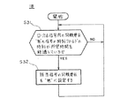
G 同報要求解除手段18の動作(図11)
これまでの同報要求通知だけのプログラムでは、同報要求が増加するだけで減少することがない。しかし、実際には、連動設定の変更、システム構成の変化等によって、同報要求が不要になることがある。ただし、不要になった同報要求の解除は、それほど緊急性を必要とするものではない。
【0038】
ステップS31でローカル信号X内の同報要求「有」の信号の時刻フィールドの最終要求受信時刻が所定時間を経過するのを待つ。所定時間が経過すれば、ステップS32で該当する信号の同報要求を「無」に設定してステップS31へ戻る。ここで、所定時間は図10のステップS28の同報要求を再設定する所定時間よりも十分に長い時間でなくてはならない。これにより、不要となった同報要求は自動的に解除される。また、接続のトラブル等によって誤解除されてしまったときは、図8のプログラムによっていったんデータが不定になるが、再度同報要求が通知され、同報送信が復旧する。
【0039】
H 外部信号設定手段19の動作(図12)
外部信号Yの参照は、分散制御装置6A〜6N間の設備8A〜8Nの連動制御を行うときに、他の分散制御装置6A〜6Nの信号を必要とするときなどに必要となる。例えば、テナント在/不在情報に連動して、エレベーターのかご呼びサービス切放しをしたり、空調及び照明を制御したりするなどが考えられる。
【0040】
ステップS35で連動テーブルの設定変更があるかを判断し、設定変更がなければステップS35へ戻り、設定変更があればステップS36へ進む。ステップS36でその設定変更が外部信号Yの登録かを判断し、外部信号Yの登録であれば、ステップS37へ進み、外部信号Yを登録し、その信号の同報要求を同報要求送信手段17に対して指示してステップS35へ戻る。ステップS35で外部信号Yの登録でないと判断すると、ステップS38へ進み、外部信号Yの削除かを判断する。
【0041】
外部信号Yの削除でなければステップS35へ戻り、外部信号Yの削除であればステップS39へ進む。ステップS39で他の連動設定等で該当する信号を使用していなければ、外部信号Yのテーブルから削除する。
【0042】
このようにして、分散制御装置6A〜6Nの中で、他の分散制御装置6A〜6Nが参照が必要となったときに、外部信号Yとして登録し、同報通信によって信号の状態変化の通知を受けることにより参照することが可能となる。また、ネットワークのトラブル、分散制御装置6A〜6Nの故障等により、外部信号Yの同報の状態変化が通知されないことを検知し、データの信頼性を確保することが可能となる。また、同報要求による状態送信を定期的に更新することにより、常時同報要求の整合性を図ることが可能になる。
【0043】
【発明の効果】
以上説明したとおりこの発明の第1発明では、分散制御装置のそれぞれに、設備の状態を示すローカル信号が登録され、かつこの登録されたローカル信号の内要求があれば同報通信により他の分散制御装置へ通知するローカル信号が指示された信号データベースを備え、他の分散制御装置の信号データベースのローカル信号を参照することを、他の分散制御装置へ同報通信によって要求し、かつこれを所定時間経過後に再通知し、この要求を外部信号として受信した他の分散制御装置は、その信号データベースの該当ローカル信号の状態変化を同報通信によって通知し、かつこれを所定時間経過後に再通知するようにしたため、他の分散制御装置の信号を、特定の手続きをすることなく、簡単かつ確実に参照することができるとともに、同報通信に伴う受信の不確実性を補うことができる。
【0044】
また、第2発明では、他の分散制御装置からの同報通信による外部信号の状態変化通知が不通になったことを検知し、信号データベース内の外部信号の状態を不定の状態に設定し、同報要求送信手段に対して該当信号の同報要求を送信することを指示するようにしたため、信号データの信頼性を確保することができる。
【0045】
また、第3発明では、同報通信により状態変化の通知が要求されているローカル信号を定期的に送信し、同報要求送信手段で設定された所定時間よりも十分長い時間経過しても通知要求のないローカル信号について通知要求を解除するようにしたため、同報要求による状態送信は定期的に更新され、常時同報要求の整合性を図ることができる。
【0046】
また、第4発明では、他の分散制御装置に接続されたビル内設備の状態を示す外部信号を信号データベースに登録し、この外部信号の状態変化の通知を受けることの要求の送信を指示するようにしたため、分散制御装置間の設備の連動制御を実行するときに必要な信号を得ることができる。
【0047】
また、第5発明では、分散制御装置のそれぞれに設けられた信号データベースに設備の状態を示すローカル信号を登録し、かつこの登録されたローカル信号の内要求があれば同報通信により他の分散制御装置へ通知するローカル信号を指示するステップと、他の分散制御装置の信号データベースのローカル信号を参照することを他の分散制御装置へ同報通信によって要求し、かつこれを所定時間経過後に再通知するステップと、要求を外部信号として受信した他の分散制御装置はその信号データベースの該当ローカル信号の状態変化を同報通信によって通知し、かつこれを所定時間経過後に再通知するステップとを備えたため、第1発明と同様の効果がある。
【図面の簡単な説明】
【図1】 この発明の実施の形態及び従来のビル管理装置を示す全体構成図。
【図2】 この発明の実施の形態及び従来のビル管理装置を示す同報通信機能説明図。
【図3】 この発明の実施の形態を示す分散制御装置のブロック線図。
【図4】 図3の信号データベースの内容図。
【図5】 図3の信号状態変化手段の動作フローチャート。
【図6】 図3の信号状態同報受信手段の動作フローチャート。
【図7】 図3の信号状態同報送信手段の動作フローチャート。
【図8】 図3の信号状態不定検出手段の動作フローチャート。
【図9】 図3の同報要求受信手段の動作フローチャート。
【図10】 図3の同報要求送信手段の動作フローチャート。
【図11】 図3の同報要求解除手段の動作フローチャート。
【図12】 図3の外部信号設定手段の動作フローチャート。
【符号の説明】
5 構内変換機、6A〜6N 分散制御装置、7A〜7B 設備制御器、8A〜8N ビル内設備、11 信号データベース、12 信号状態変化手段、13 信号状態同報受信手段、14 信号状態同報送信手段、15 信号状態不定検出手段、16 同報要求受信手段、17 同報要求送信手段、18 同報要求解除手段、19 外部信号設定手段。[0001]
BACKGROUND OF THE INVENTION
The present invention relates to an apparatus for managing facilities in a building by a central monitoring apparatus and a distributed control apparatus connected via a network having a broadcast communication function, and a management method therefor.
[0002]
[Prior art]
Conventionally, the state of equipment in a building is captured and stored in a central monitoring device via an equipment controller. All signal status monitoring and control programs are executed by the central monitoring device, and are monitored and controlled via the equipment controller.
However, in recent years, network technology has been developed, and a management system based on autonomous distributed control that places a relatively small distributed control device and controls the system while communicating with each other is attracting attention.
[0003]
Autonomous decentralized control requires higher speed and larger capacity control than the central monitoring device because the reliability is increased by distributing risk and the functions are distributed to each distributed control device compared to the central monitoring method. However, there are many advantages such as that the system can be configured at a low price and that the system can be easily expanded.
[0004]
FIGS. 1 and 2 are views showing a conventional autonomous distributed building management apparatus disclosed in, for example, 1996 Patent Application No. 3587. FIG. 1 is an overall configuration diagram, and FIG. 2 is an explanatory diagram of a broadcast communication function. It is.
Details of FIGS. 1 and 2 will be described later, but an outline thereof will be described.
[0005]
The signals of the facilities 8A to 8N are taken into the respective distributed control devices 6A to 6N via the
[0006]
However, since the functions are distributed to the distributed control devices 6A to 6N, it is necessary to devise how to realize signal exchange between the distributed control devices 6A to 6N. Here, a point number is given to each of the facilities 8A to 8N to make it a local signal, and further, a point number is given to all the distributed control devices 6A to 6N in common to make this a global signal. The global point definition table defines which distributed control device 6A to 6N actually corresponds to each global signal.
[0007]
The local signals of the distributed control devices 6A to 6N are notified only to the central monitoring device 1, and the global signal is notified to the central monitoring device 1, and also notified to the distributed control devices 6A to 6N by the broadcast communication function. As shown in FIG. 2, in the broadcast communication, all the messages output from the transmission destination are transmitted to the slave station, and the message can be easily transmitted. Since there is no guarantee that it will be transmitted reliably, a program that covers it is required.
[0008]
[Problems to be solved by the invention]
In the conventional building management apparatus as described above, a part of the local signal is referred to as a global signal and is shared by all the distributed control apparatuses 6A to 6N. Therefore, between the distributed control apparatuses 6A to 6N. However, there is a problem that the setting of the distributed control devices 6A to 6N is difficult to understand and difficult.
[0009]
The present invention has been made to solve the above-described problems, and eliminates the difficulty and difficulty of setting, and allows a distributed control device to freely refer to signals of other distributed control devices, and its The purpose is to provide a management method.
[0010]
[Means for Solving the Problems]
In the building management apparatus according to the first aspect of the present invention, a local signal indicating the state of the facility is registered in each of the distributed control apparatuses, and if there is a request for the registered local signal, other communication is performed by broadcast communication. A signal database in which a local signal to be notified to the distributed control apparatus is provided , and the other distributed control apparatus is requested by broadcast communication to refer to the local signal in the signal database of the other distributed control apparatus, and re notification after a predetermined time has elapsed, again the request other distributed control system which receives as an external signal, and notifies the state change of the relevant local signal of the signal database by broadcast, and this after a predetermined time has elapsed It is a notification .
[0011]
The building management apparatus according to the second aspect of the present invention is the one according to the first aspect of the invention, which detects that the external signal state change notification by broadcast communication from another distributed control apparatus has been interrupted, The state of the external signal is set to an indeterminate state, and the broadcast request transmission means is instructed to transmit the broadcast request for the corresponding signal .
[0012]
Further, the building management apparatus according to the third aspect of the present invention is the one according to the first aspect , wherein a local signal for which notification of a state change is requested by broadcast communication is periodically transmitted and set by the broadcast request transmission means. The notification request is canceled for a local signal for which there is no notification request even if a time sufficiently longer than a predetermined time has elapsed .
[0013]
The building management device according to the fourth invention is the one according to the first invention, wherein an external signal indicating the state of the building equipment connected to another distributed control device is registered in the signal database, and the state change of the external signal It is instructed to send a request to receive the notification.
[0014]
In the building management method according to the fifth aspect of the present invention, a local signal indicating the state of equipment is registered in a signal database provided in each of the distributed control devices, and if there is a request for the registered local signal, the broadcast is transmitted. A step of instructing a local signal to be notified to another distributed control device by communication and a request to the other distributed control device by broadcast communication to refer to a local signal in the signal database of the other distributed control device ; and The step of re-notifying after the elapse of a predetermined time and the other distributed control apparatus that has received the request as an external signal notify the change of the state of the corresponding local signal in the signal database by broadcast communication , and re-notify this after elapse of the predetermined time. it is the ash and a step of.
[0015]
DETAILED DESCRIPTION OF THE INVENTION
Embodiment 1 FIG.
1 to 12 are diagrams showing an embodiment of the first to sixth inventions of the present invention. FIG. 1 is an overall configuration diagram, FIG. 2 is a broadcast communication function explanatory diagram, and FIG. 3 is a block diagram of a distributed control apparatus. 4 is a signal database content diagram, and FIGS. 5 to 12 are operation flowcharts. In FIG.
[0016]
In FIG. 1, reference numeral 1 denotes a central monitoring device that manages the entire building, and is connected to a LAN (local area network) 3 together with
[0017]
Here, the distributed control devices 6A to 6N have an interface function, and interface digital input and digital output of parallel signals, analog input and analog output, and the like. In some cases, the interface is performed by serial transmission. Also, the distributed control devices 6A to 6N store information on the facilities 8A to 8N inside and notify the transmission interface device 4 and other distributed control devices 6A to 6N via the
[0018]
The distributed control devices 6A to 6N also control the facilities 8A to 8N according to control commands from the
[0019]
FIG. 2 shows an overview of the broadcast communication function.
The broadcast communication function is a function for transmitting all the messages output from the transmission destination to the slave stations of a preset group, for example, as disclosed in Japanese Patent Laid-Open No. 8-46635. Messages can be easily transmitted from the distributed control devices 6A to 6N to the central monitoring device 1 and other distributed control devices 6A to 6N. However, in the case of the broadcast communication function, there is no guarantee that the data is reliably transmitted to the other station, so a program for covering it is necessary.
[0020]
Moreover, since the
In recent years, a LAN having a broadcast communication function (for example, a UDP / IP broadcast function) is also widely used. Therefore, a configuration in which a distributed control device, a central monitoring device, and a monitoring terminal are connected via a LAN is also possible. is there.
[0021]
On the other hand, the operator of the building management apparatus is in the disaster prevention center or the like and monitors the entire building. Therefore, information of each of the distributed control devices 6A to 6N is collected in the central monitoring device 1 via the transmission interface device 4. Information collected in the central monitoring device 1 is searched and processed in response to requests from the
[0022]
Generally, since the central monitoring device 1 and the
[0023]
In FIG. 3, reference numeral 11 denotes a signal database for storing signal states. With this as the center, signal state changing means 12, signal state broadcast receiving means 13, signal state broadcast transmitting means 14, signal state indefinite detection means 15, A broadcast
[0024]
The signal database 11 is configured as shown in FIG. 4 and includes a local signal X and an external signal Y, and the state of the equipment is managed by numbers called point numbers.
[0025]
Further, the point numbers 050310 to 060100 of the external signal Y are signals managed by the other distributed control devices 6A to 6N, and the external signal Y is registered when reference is required for interlocking control or the like.
Here, the point numbers are individually determined for the entire apparatus and do not overlap in all the distributed control apparatuses 6A to 6N. For example, the upper 2 digits may be a distributed control device serial number, and the lower 4 digits may be a local signal number. The number of point numbers may be determined as necessary.
[0026]
The signal database 11 includes attributes such as the signal type and equipment name of each point, the current signal state, broadcast request presence / absence information for realizing the functions of this embodiment, and data fields of time information. have.
The signal change of the local signal X is set with respect to the signal database 11 by information received by the signal
[0027]
Next, the operation of this embodiment will be described with reference to FIGS.
A. Operation of signal state changing means 12 (FIG. 5)
In step S1, a signal state change notification from the
[0028]
Operation of B signal state broadcast receiving means 13 (FIG. 6)
In step S6, it waits for notification of the state of the external signal Y from the other distributed control devices 6A to 6N by broadcast communication. If there is a notification, the external signal Y is registered in the external signal Y in the signal database 11 in step S7. Judgment is made. If it is not registered, the process returns to step S6. If it is registered, the current state of the signal Y is set in the notified information in step S8, and the time at that time is set, and the process returns to step S6. Here, the current time may not be the time of year / month / day / hour / second, but may be a count in the distributed control devices 6A to 6N as long as the passage of time can be determined by means described later.
[0029]
C Operation of signal state broadcast transmission means 14 (FIG. 7)
In step S11, it is determined whether or not the state of the signal requested for broadcast in the local signal X, that is, the signal of the broadcast request “present” has changed, and if it has changed, the process proceeds to step S12. Is notified to the other distributed control devices 6A to 6N by broadcast communication, and the process returns to step S11. This signal is a notification received by the signal state broadcast receiving means 13. If it is determined in step S11 that the signal state has not changed, the process proceeds to step S13.
[0030]
In step S13, it is determined whether a predetermined time has elapsed. If not, the process returns to step S11, and if it has elapsed, the process proceeds to step S14. In step S14, the state of the broadcast request “present” signal in the local signal X is notified, and the process returns to step S11. Since this is a communication method in which broadcast communication does not take confirmation from the other party, it may not be received by the other party's distributed control devices 6A to 6N. Because.
[0031]
Operation of D signal state indefinite detection means 15 (FIG. 8)
This operation is an operation for checking an event in which broadcast communication is not transmitted.
In step S16, it is determined whether there is a signal for which the setting of the state is not performed for a predetermined time in the external signal Y. If there is no corresponding signal, the process returns to step S16, and if there is a corresponding signal, the process proceeds to step S17. In step S17, the current state of the signal is set to “undefined”, and the time is set as the broadcast reception time of the signal.
[0032]
The logic of referring to the signal that has become “indefinite” is characterized by the application program, and it can be considered that there is no setting or the control is invalidated. In any case, it is necessary to clearly distinguish the indeterminate state. In addition, the broadcast communication cannot be received because the other party's distributed control devices 6A to 6N are down or the broadcast communication request has been canceled. The
[0033]
E Operation of broadcast request receiving means 16 (FIG. 9)
In step S21, it waits for reception of a broadcast request from the other distributed control devices 6A to 6N. If received, it determines in step S22 whether the broadcast request corresponds to a local signal in this device, and responds. If not, the process returns to step S21, and if it is a corresponding one, the process proceeds to step S23. In step S 23, the broadcast request “present” is set for the local signal X in the signal database 11. Also, the current time is set in the time field, and the process returns to step S21.
[0034]
At this time, the broadcast request may be requested from a plurality of distributed control devices 6A to 6N, but is collected into the presence / absence information. This is because the system configuration does not require the number of distributed control devices 6A to 6N to be conscious and increases flexibility. However, the cancellation of the broadcast request is determined based on the request reception time set at the same time, as will be described later.
[0035]
F Operation of broadcast request transmission means 17 (FIG. 10)
In a function such as interlock control between the distributed control devices 6A to 6N, when registration for referring to the signals of the other distributed control devices 6A to 6N is performed, transmission of the broadcast request is sent to the broadcast request transmitting means 17. Is instructed. In step S26, it is determined whether or not there is this instruction. If there is an instruction, the process proceeds to step S27, a broadcast request for the corresponding signal is requested to the other distributed control devices 6A to 6N by broadcast communication, and the process proceeds to step S26. Return. Then, the distributed control devices 6A to 6N that have received the broadcast request start transmission of broadcast communication in the signal state.
[0036]
If it is determined in step S26 that there is no transmission instruction, the process proceeds to step S28, where it is determined whether a predetermined time has elapsed. If not, the process returns to step S26, and if it has elapsed, the process proceeds to step S29. In step S29, the broadcast request for the external signal Y is notified again, and the process returns to step S26. Thus, the broadcast request is updated at predetermined time intervals.
[0037]
G Operation of broadcast request canceling means 18 (FIG. 11)
In the conventional program only for notification of broadcast requests, the number of broadcast requests only increases and does not decrease. However, in practice, a broadcast request may not be required due to a change in interlocking settings, a change in system configuration, or the like. However, canceling a broadcast request that is no longer necessary is not so urgent.
[0038]
In step S31, the process waits for the final request reception time in the time field of the broadcast request “present” signal in the local signal X to pass a predetermined time. If the predetermined time has elapsed, the broadcast request for the corresponding signal is set to “None” in step S32, and the process returns to step S31. Here, the predetermined time must be sufficiently longer than the predetermined time for resetting the broadcast request in step S28 of FIG. As a result, the broadcast request that has become unnecessary is automatically canceled. In addition, if the connection is canceled due to a connection trouble or the like, the data is temporarily undefined by the program shown in FIG. 8, but a broadcast request is notified again, and the broadcast transmission is restored.
[0039]
H Operation of external signal setting means 19 (FIG. 12)
The reference of the external signal Y is necessary when the signals of the other distributed control devices 6A to 6N are required when performing interlock control of the facilities 8A to 8N between the distributed control devices 6A to 6N. For example, in conjunction with tenant presence / absence information, the elevator car call service may be disconnected, air conditioning and lighting may be controlled.
[0040]
In step S35, it is determined whether there is a setting change in the interlocking table. If there is no setting change, the process returns to step S35, and if there is a setting change, the process proceeds to step S36. In step S36, it is determined whether the setting change is registration of the external signal Y. If it is registration of the external signal Y, the process proceeds to step S37, where the external signal Y is registered, and a broadcast request transmission means for the signal is sent. 17 is instructed to return to step S35. If it is determined in step S35 that the external signal Y is not registered, the process proceeds to step S38 to determine whether the external signal Y is deleted.
[0041]
If the external signal Y is not deleted, the process returns to step S35, and if the external signal Y is deleted, the process proceeds to step S39. If the corresponding signal is not used in other interlocking settings or the like in step S39, it is deleted from the external signal Y table.
[0042]
In this way, when the other distributed control devices 6A to 6N need to be referred to among the distributed control devices 6A to 6N, they are registered as external signals Y, and notification of signal state changes by broadcast communication It becomes possible to refer by receiving. Further, it is possible to detect that the broadcast signal state change of the external signal Y is not notified due to a network trouble, a failure of the distributed control devices 6A to 6N, and the like, and to ensure data reliability. In addition, by regularly updating the status transmission by the broadcast request, it becomes possible to constantly match the broadcast request.
[0043]
【The invention's effect】
As described above, in the first invention of the present invention, a local signal indicating the state of the facility is registered in each of the distributed control devices, and if there is a request for the registered local signal, another distributed signal is transmitted by broadcast communication. and a signal database local signal is instructed to notify the controller that references a local signal of the signal database of other distributed control system, and required by broadcast to other distributed control system, and which a predetermined Other distributed control devices that have re-notified after the elapse of time and received this request as an external signal notify the state change of the corresponding local signal in the signal database by broadcast communication , and re-notify this after the elapse of a predetermined time. because the way, the signals of other distributed control system, without any particular procedure, it is possible to see easily and reliably, distribution You can compensate for the uncertainty of received accompanying the signal.
[0044]
Further, in the second invention, it is detected that the external signal state change notification by broadcast communication from another distributed control device is interrupted, and the state of the external signal in the signal database is set to an indeterminate state , Since the broadcast request transmission means is instructed to transmit a broadcast request for the corresponding signal, the reliability of the signal data can be ensured.
[0045]
Further, in the third invention, a local signal for which notification of a state change is requested by broadcast communication is periodically transmitted, and notification is made even if a time sufficiently longer than a predetermined time set by the broadcast request transmission means has elapsed. Since the notification request is canceled for the local signal that is not requested, the status transmission by the broadcast request is periodically updated, and the consistency of the broadcast request can be always achieved.
[0046]
In the fourth aspect of the invention, an external signal indicating the state of the building equipment connected to another distributed control device is registered in the signal database, and an instruction to transmit a request for receiving notification of a change in the state of the external signal is given. Since it did in this way, a signal required when performing the interlock control of the installation between distributed control apparatuses can be obtained.
[0047]
In the fifth invention, a local signal indicating the state of the facility is registered in a signal database provided in each of the distributed control devices, and if there is a request for the registered local signal, other distributed signals are transmitted by broadcast communication. A step of instructing a local signal to be notified to the control device and a request for referring to a local signal in the signal database of the other distributed control device to the other distributed control device by broadcast communication , and this is repeated after a predetermined time has elapsed. A step of notifying, and another distributed control device that has received the request as an external signal notifies the state change of the corresponding local signal in the signal database by broadcast communication and re-notifies this after a predetermined time has elapsed. Therefore, there is an effect similar to that of the first invention.
[Brief description of the drawings]
FIG. 1 is an overall configuration diagram showing an embodiment of the present invention and a conventional building management apparatus.
FIG. 2 is an explanatory diagram of a broadcast communication function showing an embodiment of the present invention and a conventional building management apparatus.
FIG. 3 is a block diagram of a distributed control apparatus showing an embodiment of the present invention.
4 is a content diagram of the signal database in FIG. 3. FIG.
FIG. 5 is an operation flowchart of the signal state changing unit in FIG. 3;
6 is an operation flowchart of the signal state broadcast receiving means of FIG. 3;
7 is an operation flowchart of the signal state broadcast transmission means of FIG. 3;
8 is an operation flowchart of signal state indefinite detection means in FIG. 3;
9 is an operation flowchart of the broadcast request receiving means of FIG. 3;
10 is an operation flowchart of the broadcast request transmission unit of FIG. 3;
11 is an operation flowchart of the broadcast request canceling means in FIG. 3;
12 is an operation flowchart of the external signal setting unit in FIG. 3;
[Explanation of symbols]
5 Private branch converter, 6A-6N Distributed control device, 7A-7B Equipment controller, 8A-8N Building equipment, 11 Signal database, 12 Signal state changing means, 13 Signal status broadcast receiving means, 14 Signal status broadcast transmission Means 15 signal state indefinite detection means 16 broadcast request receiving means 17 broadcast request transmitting means 18 broadcast request canceling means 19 external signal setting means
Claims (5)
Priority Applications (1)
| Application Number | Priority Date | Filing Date | Title |
|---|---|---|---|
| JP17234797A JP3676908B2 (en) | 1997-06-27 | 1997-06-27 | Building management apparatus and management method thereof |
Applications Claiming Priority (1)
| Application Number | Priority Date | Filing Date | Title |
|---|---|---|---|
| JP17234797A JP3676908B2 (en) | 1997-06-27 | 1997-06-27 | Building management apparatus and management method thereof |
Publications (2)
| Publication Number | Publication Date |
|---|---|
| JPH1118166A JPH1118166A (en) | 1999-01-22 |
| JP3676908B2 true JP3676908B2 (en) | 2005-07-27 |
Family
ID=15940231
Family Applications (1)
| Application Number | Title | Priority Date | Filing Date |
|---|---|---|---|
| JP17234797A Expired - Lifetime JP3676908B2 (en) | 1997-06-27 | 1997-06-27 | Building management apparatus and management method thereof |
Country Status (1)
| Country | Link |
|---|---|
| JP (1) | JP3676908B2 (en) |
Families Citing this family (2)
| Publication number | Priority date | Publication date | Assignee | Title |
|---|---|---|---|---|
| JP4719993B2 (en) * | 2001-03-26 | 2011-07-06 | パナソニック電工株式会社 | Central supervisory control system |
| JP4770629B2 (en) * | 2006-07-26 | 2011-09-14 | パナソニック電工株式会社 | Remote monitoring and control system |
-
1997
- 1997-06-27 JP JP17234797A patent/JP3676908B2/en not_active Expired - Lifetime
Also Published As
| Publication number | Publication date |
|---|---|
| JPH1118166A (en) | 1999-01-22 |
Similar Documents
| Publication | Publication Date | Title |
|---|---|---|
| JP4406516B2 (en) | Elevator management device and elevator system | |
| JP2006195554A (en) | Integrated supervision system | |
| JP4386955B1 (en) | Distributed monitoring and control system and data updating method for the same | |
| JP3676908B2 (en) | Building management apparatus and management method thereof | |
| JP4916283B2 (en) | Power system operation monitoring control system and method | |
| JP2008172525A (en) | Telephone reception equipment of service window | |
| JP3346144B2 (en) | Building management equipment | |
| JP2003221845A (en) | Remote control system for waterworks and sewage facilities | |
| JP2004104753A (en) | Remote monitoring type illumination system, repeater, and server device | |
| JP3641105B2 (en) | Building management equipment | |
| JPS63155357A (en) | Building group controlling system | |
| JP2004236176A (en) | Monitor system | |
| JPH082838A (en) | Remote building control device | |
| JPH0622367A (en) | Alarm monitor system at plural points | |
| JPS63164667A (en) | Group management system | |
| JP2021149386A (en) | Monitoring system | |
| JPS63155398A (en) | Remote building managing system | |
| JPH06333188A (en) | Remote supervisory center equipment | |
| JPH0725495U (en) | Remote monitoring center device | |
| JPS62171258A (en) | Building management system | |
| JPH06152798A (en) | Remote monitoring center device | |
| JPH0691587B2 (en) | Back-up method of building group management system | |
| JPH06261011A (en) | Status data transmission method | |
| JPH09102985A (en) | Building group managing system | |
| JP2004120549A (en) | Wireless mobile communication system |
Legal Events
| Date | Code | Title | Description |
|---|---|---|---|
| A977 | Report on retrieval |
Free format text: JAPANESE INTERMEDIATE CODE: A971007 Effective date: 20041130 |
|
| A131 | Notification of reasons for refusal |
Free format text: JAPANESE INTERMEDIATE CODE: A131 Effective date: 20050215 |
|
| A521 | Written amendment |
Free format text: JAPANESE INTERMEDIATE CODE: A523 Effective date: 20050317 |
|
| TRDD | Decision of grant or rejection written | ||
| A01 | Written decision to grant a patent or to grant a registration (utility model) |
Free format text: JAPANESE INTERMEDIATE CODE: A01 Effective date: 20050426 |
|
| A61 | First payment of annual fees (during grant procedure) |
Free format text: JAPANESE INTERMEDIATE CODE: A61 Effective date: 20050502 |
|
| R150 | Certificate of patent or registration of utility model |
Free format text: JAPANESE INTERMEDIATE CODE: R150 |
|
| FPAY | Renewal fee payment (event date is renewal date of database) |
Free format text: PAYMENT UNTIL: 20080513 Year of fee payment: 3 |
|
| FPAY | Renewal fee payment (event date is renewal date of database) |
Free format text: PAYMENT UNTIL: 20090513 Year of fee payment: 4 |
|
| FPAY | Renewal fee payment (event date is renewal date of database) |
Free format text: PAYMENT UNTIL: 20100513 Year of fee payment: 5 |
|
| FPAY | Renewal fee payment (event date is renewal date of database) |
Free format text: PAYMENT UNTIL: 20100513 Year of fee payment: 5 |
|
| FPAY | Renewal fee payment (event date is renewal date of database) |
Free format text: PAYMENT UNTIL: 20110513 Year of fee payment: 6 |
|
| FPAY | Renewal fee payment (event date is renewal date of database) |
Free format text: PAYMENT UNTIL: 20110513 Year of fee payment: 6 |
|
| FPAY | Renewal fee payment (event date is renewal date of database) |
Free format text: PAYMENT UNTIL: 20120513 Year of fee payment: 7 |
|
| FPAY | Renewal fee payment (event date is renewal date of database) |
Free format text: PAYMENT UNTIL: 20120513 Year of fee payment: 7 |
|
| FPAY | Renewal fee payment (event date is renewal date of database) |
Free format text: PAYMENT UNTIL: 20130513 Year of fee payment: 8 |
|
| FPAY | Renewal fee payment (event date is renewal date of database) |
Free format text: PAYMENT UNTIL: 20140513 Year of fee payment: 9 |
|
| R250 | Receipt of annual fees |
Free format text: JAPANESE INTERMEDIATE CODE: R250 |
|
| R250 | Receipt of annual fees |
Free format text: JAPANESE INTERMEDIATE CODE: R250 |
|
| EXPY | Cancellation because of completion of term |