JP3674036B2 - Ink cartridge, ink jet recording apparatus using the same, and recording head cleaning control method in the same - Google Patents
Ink cartridge, ink jet recording apparatus using the same, and recording head cleaning control method in the same Download PDFInfo
- Publication number
- JP3674036B2 JP3674036B2 JP2001553131A JP2001553131A JP3674036B2 JP 3674036 B2 JP3674036 B2 JP 3674036B2 JP 2001553131 A JP2001553131 A JP 2001553131A JP 2001553131 A JP2001553131 A JP 2001553131A JP 3674036 B2 JP3674036 B2 JP 3674036B2
- Authority
- JP
- Japan
- Prior art keywords
- ink
- cartridge
- negative pressure
- recording apparatus
- flow path
- Prior art date
- Legal status (The legal status is an assumption and is not a legal conclusion. Google has not performed a legal analysis and makes no representation as to the accuracy of the status listed.)
- Expired - Fee Related
Links
Images


Classifications
-
- B—PERFORMING OPERATIONS; TRANSPORTING
- B41—PRINTING; LINING MACHINES; TYPEWRITERS; STAMPS
- B41J—TYPEWRITERS; SELECTIVE PRINTING MECHANISMS, i.e. MECHANISMS PRINTING OTHERWISE THAN FROM A FORME; CORRECTION OF TYPOGRAPHICAL ERRORS
- B41J2/00—Typewriters or selective printing mechanisms characterised by the printing or marking process for which they are designed
- B41J2/005—Typewriters or selective printing mechanisms characterised by the printing or marking process for which they are designed characterised by bringing liquid or particles selectively into contact with a printing material
- B41J2/01—Ink jet
- B41J2/135—Nozzles
- B41J2/165—Preventing or detecting of nozzle clogging, e.g. cleaning, capping or moistening for nozzles
- B41J2/16517—Cleaning of print head nozzles
- B41J2/1652—Cleaning of print head nozzles by driving a fluid through the nozzles to the outside thereof, e.g. by applying pressure to the inside or vacuum at the outside of the print head
- B41J2/16532—Cleaning of print head nozzles by driving a fluid through the nozzles to the outside thereof, e.g. by applying pressure to the inside or vacuum at the outside of the print head by applying vacuum only
-
- B—PERFORMING OPERATIONS; TRANSPORTING
- B41—PRINTING; LINING MACHINES; TYPEWRITERS; STAMPS
- B41J—TYPEWRITERS; SELECTIVE PRINTING MECHANISMS, i.e. MECHANISMS PRINTING OTHERWISE THAN FROM A FORME; CORRECTION OF TYPOGRAPHICAL ERRORS
- B41J2/00—Typewriters or selective printing mechanisms characterised by the printing or marking process for which they are designed
- B41J2/005—Typewriters or selective printing mechanisms characterised by the printing or marking process for which they are designed characterised by bringing liquid or particles selectively into contact with a printing material
- B41J2/01—Ink jet
- B41J2/135—Nozzles
- B41J2/165—Preventing or detecting of nozzle clogging, e.g. cleaning, capping or moistening for nozzles
- B41J2/16505—Caps, spittoons or covers for cleaning or preventing drying out
- B41J2/16508—Caps, spittoons or covers for cleaning or preventing drying out connected with the printer frame
-
- B—PERFORMING OPERATIONS; TRANSPORTING
- B41—PRINTING; LINING MACHINES; TYPEWRITERS; STAMPS
- B41J—TYPEWRITERS; SELECTIVE PRINTING MECHANISMS, i.e. MECHANISMS PRINTING OTHERWISE THAN FROM A FORME; CORRECTION OF TYPOGRAPHICAL ERRORS
- B41J2/00—Typewriters or selective printing mechanisms characterised by the printing or marking process for which they are designed
- B41J2/005—Typewriters or selective printing mechanisms characterised by the printing or marking process for which they are designed characterised by bringing liquid or particles selectively into contact with a printing material
- B41J2/01—Ink jet
- B41J2/17—Ink jet characterised by ink handling
- B41J2/175—Ink supply systems ; Circuit parts therefor
- B41J2/17503—Ink cartridges
- B41J2/17513—Inner structure
-
- B—PERFORMING OPERATIONS; TRANSPORTING
- B41—PRINTING; LINING MACHINES; TYPEWRITERS; STAMPS
- B41J—TYPEWRITERS; SELECTIVE PRINTING MECHANISMS, i.e. MECHANISMS PRINTING OTHERWISE THAN FROM A FORME; CORRECTION OF TYPOGRAPHICAL ERRORS
- B41J2/00—Typewriters or selective printing mechanisms characterised by the printing or marking process for which they are designed
- B41J2/005—Typewriters or selective printing mechanisms characterised by the printing or marking process for which they are designed characterised by bringing liquid or particles selectively into contact with a printing material
- B41J2/01—Ink jet
- B41J2/17—Ink jet characterised by ink handling
- B41J2/175—Ink supply systems ; Circuit parts therefor
- B41J2/17503—Ink cartridges
- B41J2/1752—Mounting within the printer
- B41J2/17523—Ink connection
-
- B—PERFORMING OPERATIONS; TRANSPORTING
- B41—PRINTING; LINING MACHINES; TYPEWRITERS; STAMPS
- B41J—TYPEWRITERS; SELECTIVE PRINTING MECHANISMS, i.e. MECHANISMS PRINTING OTHERWISE THAN FROM A FORME; CORRECTION OF TYPOGRAPHICAL ERRORS
- B41J2/00—Typewriters or selective printing mechanisms characterised by the printing or marking process for which they are designed
- B41J2/005—Typewriters or selective printing mechanisms characterised by the printing or marking process for which they are designed characterised by bringing liquid or particles selectively into contact with a printing material
- B41J2/01—Ink jet
- B41J2/17—Ink jet characterised by ink handling
- B41J2/175—Ink supply systems ; Circuit parts therefor
- B41J2/17503—Ink cartridges
- B41J2/17533—Storage or packaging of ink cartridges
-
- B—PERFORMING OPERATIONS; TRANSPORTING
- B41—PRINTING; LINING MACHINES; TYPEWRITERS; STAMPS
- B41J—TYPEWRITERS; SELECTIVE PRINTING MECHANISMS, i.e. MECHANISMS PRINTING OTHERWISE THAN FROM A FORME; CORRECTION OF TYPOGRAPHICAL ERRORS
- B41J2/00—Typewriters or selective printing mechanisms characterised by the printing or marking process for which they are designed
- B41J2/005—Typewriters or selective printing mechanisms characterised by the printing or marking process for which they are designed characterised by bringing liquid or particles selectively into contact with a printing material
- B41J2/01—Ink jet
- B41J2/17—Ink jet characterised by ink handling
- B41J2/175—Ink supply systems ; Circuit parts therefor
- B41J2/17503—Ink cartridges
- B41J2/17553—Outer structure
-
- B—PERFORMING OPERATIONS; TRANSPORTING
- B41—PRINTING; LINING MACHINES; TYPEWRITERS; STAMPS
- B41J—TYPEWRITERS; SELECTIVE PRINTING MECHANISMS, i.e. MECHANISMS PRINTING OTHERWISE THAN FROM A FORME; CORRECTION OF TYPOGRAPHICAL ERRORS
- B41J2/00—Typewriters or selective printing mechanisms characterised by the printing or marking process for which they are designed
- B41J2/005—Typewriters or selective printing mechanisms characterised by the printing or marking process for which they are designed characterised by bringing liquid or particles selectively into contact with a printing material
- B41J2/01—Ink jet
- B41J2/17—Ink jet characterised by ink handling
- B41J2/175—Ink supply systems ; Circuit parts therefor
- B41J2/17596—Ink pumps, ink valves
-
- B—PERFORMING OPERATIONS; TRANSPORTING
- B41—PRINTING; LINING MACHINES; TYPEWRITERS; STAMPS
- B41J—TYPEWRITERS; SELECTIVE PRINTING MECHANISMS, i.e. MECHANISMS PRINTING OTHERWISE THAN FROM A FORME; CORRECTION OF TYPOGRAPHICAL ERRORS
- B41J2/00—Typewriters or selective printing mechanisms characterised by the printing or marking process for which they are designed
- B41J2/005—Typewriters or selective printing mechanisms characterised by the printing or marking process for which they are designed characterised by bringing liquid or particles selectively into contact with a printing material
- B41J2/01—Ink jet
- B41J2/17—Ink jet characterised by ink handling
- B41J2/19—Ink jet characterised by ink handling for removing air bubbles
Description
技術分野
この発明は、例えば記録用紙の幅方向に移動する記録ヘッドを備え、印刷データに基づいてインク滴を記録用紙に向かって吐出することで記録用紙上に画像を印刷するインクジェット式記録装置に関し、より詳細には、記録ヘッドのノズル開口からインクを吸引して記録ヘッドの印字機能を回復させるクリーニング処理を効果的に実行し得るインクカートリッジおよびこれを用いたインクジェット式記録装置、並びに同装置における記録ヘッドのクリーニング制御方法に関する。
背景技術
インクジェット式記録装置は、インクカートリッジからのインクの供給を受けるインクジェット式記録ヘッドと、記録用紙を記録ヘッドに対して相対的に移動させる紙送り手段が備えられ、キャリッジに搭載された記録ヘッドを記録用紙の幅方向に移動させながらインク滴を吐出させることで記録が行われる。
そしてキャリッジ上に、ブラックインクおよびイエロー、シアン、マゼンタの各カラーインクの吐出が可能な記録ヘッドを搭載し、ブラックインクによるテキスト印刷ばかりでなく、各インクの吐出割合を変えることにより、フルカラー印刷を可能としている。
前記した記録ヘッドは、圧力発生室で加圧したインクをノズルからインク滴として記録用紙に吐出させて印刷を行う関係上、例えばノズル開口からの溶媒の蒸発に起因するインク粘度の上昇や、インクの固化により、また塵埃の付着、さらには気泡の混入などにより、印刷不良を起こすという問題を抱えている。
このために、ノズル開口に目詰まりが生じた場合、またはインクカートリッジを交換した場合などには、キャッピング手段により記録ヘッドのノズル形成面を封止し、吸引ポンプからの負圧によりノズル開口からインクを吸引排出させることで、ノズル開口等におけるインク固化による目詰まりや、インク流路内への気泡の混入によるインク吐出不良を解消する機能が具備されており、これはクリーニング操作と呼ばれている。
このクリーニング操作を実行する場合においては、例えばインクカートリッジから記録ヘッドのノズル開口に至るインク流路内に、なるべく早いインクの流れを発生させることが効果的であり、これにより増粘したインクと共に、流路内に存在する気泡も排出させることができる。
しかしながら、クリーニング操作時においてインクの流速を増大させるには、大きな負圧を得るために吸引ポンプの能力を増大させる必要がある。これにはポンプの大型化と共に、ポンプを駆動するモータも大型のものを使用せざるを得ず、必然的にコストの上昇および装置全体の大型化は免れない。
さらに、記録ヘッドから大量のインクを排出させるために、インクカートリッジの寿命も短くなり、ユーザに対してランニングコストの増大を強いる結果を招来させる。
そこで、例えば日本国特開平4−1055号公報に見られるように、インクカートリッジから記録ヘッドに至るインク流路内に、開閉可能なバルブユニットを配置し、クリーニング操作にあたっては、前記バルブユニットを閉弁状態としてキャッピング手段内に負圧を印加し、キャッピング手段内の負圧が上昇した時点で前記バルブユニットを開弁させることで、記録ヘッド内のインクの流速を瞬間的に高めるように構成した記録装置が提案されている。
この構成によると、大きな負圧を得るための格別な吸引ポンプを備えることなく、記録ヘッドのノズル近傍において固化または増粘したインクを比較的容易に排出させることができるものと考えられる。そして、ノズルからの吸引作用が瞬間的になされるので、結果として比較的少ないインクの排出量でクリーニング効果を得ることが可能であると考えられる。
ところで、前記したような記録装置の多くは、一般にブラックインクおよびカラーインクを封入した各インクカートリッジが記録ヘッドを搭載したキャリッジ上に、その上部から着脱可能に装着できるように構成されており、各カートリッジはキャリッジに上向きに搭載されたインク導入部としての中空状のインク供給針(以下、中空針ともいう)を介して、記録ヘッドに対してインクが供給されるように構成されている。
そして、このような記録装置においては、記録ヘッド内でのインクの流れる流路は、非常に微細に構成されており、したがってインクカートリッジから記録ヘッドに供給されるインクは、塵埃等の異物の混入のない清浄な状態であることが要求される。
すなわち、塵埃等の異物が混入しているような場合においては、記録ヘッドのインク流路のなかでも特に狭いインク供給口や、ノズル開口部分に異物が詰まるという問題が発生し、これにより正常なインクの吐出作用が行なえなくなり、多くの場合において記録ヘッドの機能の回復は不可能となる。
そこで、一般にインク流路における記録ヘッドの川上側、例えば前記中空針とこの中空針を支持するヘッドケースとの間に異物を除去するフィルタ部材を配置し、このフィルタ部材によって記録ヘッド側への異物の侵入を防止するようにしている。
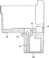
第1図は、その状況を断面状態で示したものである。符号21はその上部にインクカートリッジが装着され、インクカートリッジ側に貯留されたインクを記録ヘッド側に導出するための中空針を示す。この中空針21の上端部は先鋭状になされ、その一部にインク導出穴21aが開口されており、インクカートリッジに装着されたゴム性のパッキング部材に密着して接合された中空針21は、そのインク導出穴21aを介してインクカートリッジよりインクを導出することができるように構成されている。また、この中空針21の基端部は末広がり状になされ、したがって、その内部にはテーパ状の空間部21bが形成されている。
一方、前記中空針21の基端部を取り付ける記録ヘッドのケース20a側にも、空間部20fが形成されており、これらの空間部を挟む前記中空針21の基端部と、ヘッドケース20aとの間にはフィルタ部材22が配置されている。このフィルタ部材22を挟んだ上下に空間部を持たせることにより、フィルタ部材22の面積を実効的に広くし、フィルタ部材が持つ動圧(圧力損失)を抑えるように構成している。
第1図に示した構成からも理解できるように、中空針21内に形成されたインク流路と、フィルタ部材22とが重力方向に配置されている状態においては、例えばインクを初めて記録ヘッドの流路内へ充填する初期充填動作時においては、第1図(A)に示したように、特にフィルタ部材22の上部における中空針21内に形成されたテーパ状空間部21b内に気泡Aが残留するという現象が発生する。また、インクカートリッジを交換した際にも、フィルタ部材22の上部における空間部21bに気泡Aが侵入し、空間部21b内に気泡Aがとどまるという現象が発生する。
一方、前記したように気泡Aが残留した状態で印字を実行し、この印字の状態がフルデューティーである場合(全てのノズル開口から同時に最高周波数でインク滴を吐出する場合)には、フィルタ部材22の上流側に残留する気泡Aは、インクの流れと共にゆっくりとフィルタ部材22の近傍に移動し、インクの流速とでバランスがとれた状態となる。
そして、フルデューティー印字がさらに継続されたような場合には、気泡Aがフィルタ部材と接し、その一部が僅かながらフィルタ部材22を通過して記録ヘッド内のインク流路に至り、この気泡が記録ヘッド内のインク流路内に滞る状態となる。このような状態に陥った場合には、記録ヘッド内の気泡が印刷データに基づいて圧力室で発生した圧力変化を吸収する、いわゆるクッション作用を奏し、記録ヘッドからのインク滴の吐出が不能に陥るという問題を発生させる。
そこで、前記したような気泡を排除すべくクリーニング操作が実行されるが、前記したようにキャッピング手段内の負圧が上昇するとともに、インクカートリッジ側からインクが流れ込み、中空針21内のインクの流速はそれ程高くならない。これに伴って気泡Aは中空針21内でフィルタ部材22に接近または密着するものの、これを排出させるまでには至らないという問題を抱えている。
この発明は、前記したような状況に着眼してなされたものであり、その第1態様においては、記録ヘッドとインクカートリッジとの流路の延長を招くことなく、記録ヘッドの上流側を閉塞することができるインクカートリッジ、特に閉塞手段がインクカートリッジ側に配置された構成、およびこのインクカートリッジを好適に用いることができるインクジェット式記録装置を提供することを目的とするものである。
また、その第2態様においては、特に気泡が必ず滞留する前記フィルタ部材よりも上流側であるインクカートリッジ側に、インク流路を閉塞または流路抵抗を増大させることができる流路制御手段を配置することで、特に中空針内のフィルタ部材上にとどまる気泡に対しても、負圧を効果的に与え、またこれを瞬間的に解除させることにより、気泡がフィルタ部材を通過することができるように構成したものであり、これにより気泡の排出効果を増大させることができるインクカートリッジの構成、およびこれを好適に用いることができるインクジェット式記録装置、並びに同装置における記録ヘッドのクリーニング制御方法を提供することを目的とするものである。
また、その第3態様においては、同様にインクカートリッジ側に、インク流路を閉塞させることができる流路制御手段を配置した構成において、流路制御手段が記録装置側のインク導入部の押圧力によって開閉制御される構成を提供し、これにより前記したと同様な作用効果を得ることができるインクカートリッジの構成、およびこれを好適に用いることができるインクジェット式記録装置、並びに同装置における記録ヘッドのクリーニング制御方法を提供することを目的とするものである。
発明の開示
前記した目的を達成するために成されたこの発明にかかる第1態様においては、記録装置に対して着脱可能に装填され、記録装置側に配置されたインク導入部を介して記録ヘッドにインクを供給するようになされると共に、前記インクカートリッジに形成され、記録装置側にインクを供給するインク供給路に、外部からの圧力を受けて流路を閉塞することができる領域が形成されたインクカートリッジが提供される。
この場合、好ましくはインクを貯留するインク貯留室を備えた容器と、記録ヘッドに連通するインク供給針に接合して、前記インク貯留室内のインクを前記記録ヘッドに供給するインク供給口とが備えられる。
一方、この発明にかかる前記第1態様のインクカートリッジを好適に使用し得るインクジェット式記録装置においては、記録装置側にインクを供給するインク供給路に、外部からの圧力を受けて流路を閉塞することができる領域が形成されたインクカートリッジが着脱可能に装填され、インクカートリッジにおける前記領域を押圧することができる部材と、当該インクカートリッジからインクの供給を受けて印刷を実行する記録ヘッドと、前記記録ヘッドを封止することができるキャッピング手段と、当該キャッピング手段に負圧を供給する負圧発生手段とが備えられる。
この場合、好ましくは前記記録ヘッドに連通するインク供給針が配置され、前記インク供給針にインクカートリッジのインク供給口が接合された状態で装填されるように構成される。
前記した第1態様のインクカートリッジおよびインクジェット式記録装置の組み合わせによると、外部からの圧力を受けて流路を閉塞することができる領域がインクカートリッジに形成され、当該領域を閉塞した状態で、負圧発生手段からの負圧を印加するとキャッピング手段に負圧が蓄積される。そこで、前記領域を開放すると、インクカートリッジに強い負圧が瞬間的に作用して記録ヘッドに強いインクの流れが生じ、滞留していた気泡が移動し、引き続き作用する負圧発生手段からの負圧によるインクの流れに乗って、キャッピング手段に排出される。
また、前記した目的を達成するために成されたこの発明にかかる第2態様のインクカートリッジは、記録装置に対して着脱可能に装填され、記録装置側に配置されたインク導入部を介して記録ヘッドにインクを供給するインクカートリッジであって、インクを貯留するインク貯留室から前記インク供給口に向かって形成されたインク流路には、アクチュエータによる駆動力を受けてインク流路を閉塞または流路抵抗を増大させることができる流路制御手段が配置された構成とされる。
この場合、好ましくは前記インクカートリッジに形成されたインク供給口には、記録装置に装填された状態において、前記インク導入部に接合するパッキング部材が配置される。
そして、前記流路制御手段は、好ましくは前記アクチュエータによる駆動力を受けてインク流路を開閉することができる流路開閉手段を構成する。また、前記流路制御手段は、前記アクチュエータによる駆動力を受けてインク流路の流路抵抗を変更することができる流路抵抗変更手段を構成する場合もある。そして、好ましくは前記流路制御手段は、アクチュエータの駆動力を受けて変形する弾性素材により構成されたシール部材により構成され、前記シール部材の変形によりインク流路を閉塞または流路抵抗を増大させることができるように構成される。
この場合、好ましい実施の形態においては、前記アクチュエータが記録装置上に配置され、記録装置に装填された状態において、前記流路制御手段がアクチュエータの駆動力を受けるように構成される。また、他の好ましい実施の形態においては、前記アクチュエータが、インクカートリッジ側に搭載された構成とされる。
そして、前記したいずれの形態を利用する場合においても、複数色のインクをそれぞれ個別に貯留することができる複数のインク貯留室を備えたインクカートリッジにおいては、各インク貯留室から各インク供給口に向かって形成されたそれぞれのインク流路に、アクチュエータによる駆動力を受けてインク流路を閉塞または流路抵抗を増大させることができる流路制御手段を個別に配置することが望ましい。
加えて、前記流路制御手段は、アクチュエータによる駆動力を受けない状態においては、インク流路を開放するように構成されることが望ましい。そして、前記アクチュエータは、好ましくは電磁駆動機構により構成される。また、前記アクチュエータは、カム機構により構成される場合もある。
さらに、前記した構成のインクカートリッジにおいては、5ppm以下に脱気したインクを、前記インク貯留室に封入することが望まれる。そして、前記インクカートリッジの保存状態においては、好ましくはガスバリア性を有する包装部材によって減圧包装される。加えて、前記流路制御手段をカバー部材によって覆った状態で、前記包装部材によって減圧包装されることが望ましい。
以上のように構成されたこの発明の第2態様にかかるインクカートリッジによると、インクを貯留するインク貯留室からインク供給口に向かって形成されたインク流路に、アクチュエータによる駆動力を受けてインク流路を閉塞または流路抵抗を増大させることができる流路制御手段が配置されているので、記録装置側またはカートリッジ側に配置されたアクチュエータによって、インクカートリッジに配置された流路制御手段を開閉または流路抵抗を変更することができる。
したがって、特に気泡が必ず滞留する前記したフィルタ部材よりも上流側であるインクカートリッジ側に、流路制御手段が配置されているので、特に中空針内のフィルダ部材上にとどまる気泡に対しても効果的に負圧を与えることができ、この結果、中空針内に滞留している気泡を膨張させるなどの外部圧力が与えることができる。続いて、前記アクチュエータにより流路制御手段を動作させて、負圧を瞬間的に解除させることにより、気泡を効率的に排出させることができる。
一方、前記した第2態様にかかるインクカートリッジを好適に用いることができるインクジェット式記録装置は、印刷データに基づいてノズル開口からインク滴を吐出するインクジェット式記録ヘッドと、前記記録ヘッドのノズル形成面を封止して負圧発生手段からの負圧によりノズル開口よりインクを吸引排出させることができるキャッピング手段と、インクカートリッジからのインクを前記記録ヘッドに供給するために、インクカートリッジのインク供給口に接続されるインク導入部とが備えられ、インクカートリッジとして前記した構成のインクカートリッジを搭載したインクジェット式記録装置であって、前記キャッピング手段によって記録ヘッドのノズル形成面を封止し、前記負圧発生手段による負圧をキャッピング手段に加えて負圧を蓄積した状態で、前記アクチュエータに制御信号を与える制御手段がさらに具備され、前記制御手段からアクチュエータに供給される制御信号に基づいて、前記インクカートリッジに備えられた流路制御手段を開放または流路抵抗を低下させるように構成される。
この場合、前記インクカートリッジに形成されたインク流路の流路方向が、キャリッジの移動方向とほぼ直交する関係となるように、インクカートリッジがキャリッジに搭載されることが望ましい。
また、好ましくは前記キャッピング手段によって記録ヘッドのノズル形成面を封止し、前記負圧発生手段による負圧をキャッピング手段に加えて負圧を蓄積した状態で、インクカートリッジに備えられた流路制御手段を開放または流路抵抗を低下させる動作が、記録装置に初めてインクを充填する初期充填動作において実行されるように構成される。
また、好ましくは前記キャッピング手段によって記録ヘッドのノズル形成面を封止し、前記負圧発生手段による負圧をキャッピング手段に加えて負圧を蓄積した状態で、インクカートリッジに備えられた流路制御手段を開放または流路抵抗を低下させる動作が、ユーザによってなされる回復動作の指令が、所定の印字量の範囲内において再びなされた場合に実行されるように構成される。
一方、複数色のインクをそれぞれ個別に貯留することができるインク貯留室を備えた複数のインクカートリッジが搭載され、それぞれのインクカートリッジに配置された各流路制御手段を駆動する各アクチュエータに対して、制御信号が個別に供給されるように構成される。
また、複数色のインクをそれぞれ個別に貯留することができる複数のインク貯留室を備えたインクカートリッジを少なくとも含む複数のインクカートリッジが搭載された構成においては、それぞれのインクカートリッジに配置された各流路制御手段を駆動する各アクチュエータに対して、制御信号が個別に供給されるように構成される。
この場合、前記アクチュエータが記録装置に搭載され、当該アクチュエータは、好ましくは電磁駆動機構により構成される。また、前記アクチュエータは、カム機構により構成される場合もある。
また、搭載されたインクカートリッジにおけるインクエンド状態を検出するインクエンド検出手段がさらに具備されていることが好ましく、この場合においては、少なくとも負圧発生手段による負圧をキャッピング手段に加える状態においては、インクエンド状態を検出したインク流路に備えられた前記流路制御手段を閉塞状態に保持するように構成される。
この場合、インクエンド検出手段としては、少なくとも記録ヘッドから吐出したインク滴を計数することでインクエンド状態と判定するソフトインクエンド検出手段、またはインクが封入されたインク貯留室の物理的な変化を検出することでインクエンド状態と判定するハードインクエンド検出手段を好適に利用することができる。
そして、印刷動作を実行するに際しては、好ましくはインクエンド状態を検出したインク流路に備えられた前記流路制御手段を閉塞状態に保持し、インクエンド状態以外のインクを用いるように構成される。
この場合、インクエンド状態以外のインクのうち、イエローインクを除いた他のインクのうち、最もインク残量の多いインクによって印字動作を実行するように構成することが望ましい。
加えて、インクエンド状態以外のインクを用いて印刷動作を実行する場合においては、ホストコンピュータに搭載されたプリンタドライバのユーティリティ上において、インクエンド以外の他のインクで印刷することを報知するように構成することが望ましい。
また、インクエンド状態以外のインクを用いて印刷動作を実行するに際しては、ホストコンピュータに搭載されたプリンタドライバのユーティリティ上において、インクエンド以外の他のインクで印刷を実行するか否かの判断を要求する報知を行なうように構成することもできる。
さらに前記記録装置においては、インクカートリッジのインク供給口に接続されるインク導入部として、好ましくは、その一部にインク導出穴を開口させた中空状のインク供給針が用いられる。
さらに、前記した第2態様のインクカートリッジと記録装置との組み合わせによりなされる記録ヘッドのクリーニング制御方法は、印刷データに基づいてノズル開口からインク滴を吐出するインクジェット式記録ヘッドと、前記記録ヘッドのノズル形成面を封止して負圧発生手段からの負圧によりノズル開口よりインクを吸引排出させることができるキャッピング手段と、インクカートリッジからのインクを前記記録ヘッドに供給するために、インクカートリッジのインク供給口に接続されるインク導入部とが備えられ、前記キャッピング手段によって記録ヘッドのノズル形成面を封止し、インクカートリッジに備えられた流路制御手段を閉塞または流路抵抗を増大させた状態で負圧発生手段による負圧をキャッピング手段内に加えて負圧を蓄積させる負圧蓄積ステップと、キャッピング手段内の負圧が蓄積された状態で、インクカートリッジに備えられた流路制御手段を開放または流路抵抗を低下させる負圧解除ステップとを実行するようになされる。
この場合、前記負圧蓄積ステップと前記負圧解除ステップとが、それぞれの流路制御手段において同時に実行されるようになされたクリーニング制御方法が好適に採用される。
また、前記負圧蓄積ステップと前記負圧解除ステップとが、特定の流路制御手段において実行されるようになされるクリーニング制御方法も好適に採用することができる。
さらに、前記負圧解除ステップが、特定の流路制御手段において実行されるようになされるクリーニング制御方法も好適に採用することができる。
この場合、前記特定の流路制御手段における負圧解除ステップは、好ましくは色材濃度が高いインクが充填されているインク流路において、記録装置に搭載された制御プログラムによって実行されるようになされる。
さらに、前記した負圧解除ステップは、好ましくは記録装置における印字終了後の放置時間に応じてなされる。
一方、好ましくは前記した特定の流路制御手段において実行される負圧解除ステップは、ホストコンピュータに搭載されたプリンタドライバのユーティリティ上において、または記録装置本体上で設定された指定情報に基づいて実行されるようになされる。
前記したクリーニング制御方法を採用したインクジェット式記録装置によると、キャッピング手段によってノズル開口よりインク滴を吸引するクリーニング動作に連動して、インクカートリッジのインク流路に配置された流路制御手段を駆動し、カートリッジのインク流路を閉塞または流路抵抗を増大させるように制御される。
この状態において、負圧発生手段としての吸引ポンプが駆動され、キャッピング手段内に負圧が蓄積された状態で、インクカートリッジに配置された流路制御手段を開放させる制御シーケンスが実行される。
前記した制御シーケンスの実行により、特に中空針内のフィルタ部材上にとどまる気泡は、負圧を受けて膨張する。この状態で、中空針よりも上流側で負圧が瞬間的に解除されるため、インクの早い流れに乗って中空針内のフィルタ部材上の気泡は、記録ヘッドを介してキャッピング手段側に効果的に排出させることができる。
この場合、特に中空針内にとどまる気泡以外に、例えば記録ヘッドに形成されたインク流路におけるよどみ部分にとどまる気泡をも効果的にキャッピング手段側に排出させることができる。
また、各インクカートリッジ、または1つのカートリッジにおいても、複数色のインクを個別に貯留する例えばカラーインクカートリッジに備えられた各流路制御手段を、同時にまたは個別に制御することができる。
したがって、特定のインクが収納されたカートリッジに対応する流路制御手段を、個別に制御することができるクリーニング制御方法を採用した場合には、特定のインクに対応して効率的にクリーニング動作を実行させることができる。
例えば、色材濃度が高いブラックインクにおいては、他のインクに比較するとクリーニング動作の実行によるインク吐出能力の回復性が低いことが知見されている。
したがって、カラーインクを吐出するノズル開口における吐出能力が先に回復することが多く、このような場合においては、カラーインクのみがキャッピング手段内に多量に排出されて浪費され、ブラックインクを吐出するノズル開口には負圧が作用しにくくなるという現象が発生する。
したがって、負圧解除ステップにおいて、ブラックインクに対応する前記流路制御手段のみを開放するような制御方法を採用することで、ブラックインクを吐出するノズル開口からインクを排出させることができ、他のインクの浪費を抑えつつ、効率的なクリーニング動作を実行することができる。
また、前記した目的を達成するために成されたこの発明にかかる第3態様のインクカートリッジは、記録装置に対して着脱可能に装填され、記録装置側に配置されたインク導入部を介して記録ヘッドにインクを供給するインクカートリッジであって、前記インクカートリッジに形成されたインク供給口には、記録装置に装填された状態において記録装置側のインク導入部の押圧力を受けてインク供給口内を第1の位置および第2の位置に移動する流路制御手段が配置され、前記流路制御手段は前記第1の移動位置において、インク供給口に配置された第1パッキング部材との接合が解かれてインク貯留室からのインクの供給を可能にする開弁状態にされると共に、前記第2の移動位置において、インク供給口に配置された第2パッキング部材と接合してインク貯留室からのインクの供給を停止する閉弁状態となるように構成される。
そして、好ましくは前記流路制御手段は第1パッキング部材と接合するように、バネ部材によって付勢された構成とされる。
また、好ましい実施の形態においては、前記流路制御手段は円盤状部材により構成され、且つ前記円盤状部材の一面が第1パッキング部材に接合することで閉弁状態とされ、前記円盤状部材が第1パッキング部材と第2パッキング部材との中間点に位置することで開弁状態とされ、さらに前記円盤状部材の他面が第2パッキング部材に接合することで閉弁状態とされるように構成される。
さらに、好ましくは前記流路制御手段は円盤状部材とこの円盤状部材の移動をガイドする軸部材とにより構成され、前記円盤状部材が前記軸部材の軸方向に移動されるようにインク供給口に配置された構成とされる。
そして、前記第1パッキング部材が、記録装置側に配置された前記インク導入部に接合して、カートリッジのインク供給口との間で液密状態が保持されるように構成されることが望ましい。
この場合、好ましい実施の形態においては、前記第1パッキング部材が円筒体を構成し、記録装置側のインク導入部が中空状のインク供給針を構成しており、記録装置側のインク供給針が、第1パッキング部材を構成する前記円筒体の内周面に接合されるように構成される。
以上のように構成された第3態様のインクカートリッジによると、記録装置に装填された状態において、記録装置側のインク導入部の押圧力を受けて、インク供給口に配置された流路制御手段は第1の位置および第2の位置に移動される。前記流路制御手段が第1の位置に移動した場合においては、インク貯留室からのインクの供給を可能にする開弁状態になされ、前記流路制御手段が第2の位置に移動した場合においては、前記流路制御手段はインク貯留室からのインクの供給を停止する閉弁動作を実行するように作用するので、後述するように、記録ヘッドのクリーニング動作を実行する場合において、キャッピング手段の内部空間に効果的に負圧を蓄積させることができる。
加えて、気泡が必ず滞留する前記したフィルタ部材よりも上流側であるインクカートリッジ側に、流路制御手段が配置されているので、特に中空針内のフィルタ部材上にとどまる気泡に対しても効果的に負圧を与えることができ、この結果、中空針内に滞留している気泡を膨張させるなどの外部圧力が与えることができる。続いて、流路制御手段を動作させて、負圧を瞬間的に解除させることにより、気泡を効率的に排出させることができる。
一方、前記したインクカートリッジは、記録装置への非装填状態においては、インク供給口に配置された前記流路制御手段によって、インク供給口は閉弁状態とされる。したがって、例えばインクカートリッジの使用途中で記録装置から取り外した場合であっても、インクカートリッジからインクが漏出したり、またはインクカートリッジ内に空気が侵入するという問題を回避することができる。それ故、当該インクカートリッジを再び記録装置に装填して利用することが可能となる。
一方、前記した第3態様にかかるインクカートリッジを好適に用いることができるインクジェット式記録装置は、印刷データに基づいてノズル開口からインク滴を吐出するインクジェット式記録ヘッドと、前記記録ヘッドのノズル形成面を封止して負圧発生手段からの負圧によりノズル開口よりインクを吸引排出させることができるキャッピング手段と、インクカートリッジからのインクを前記記録ヘッドに供給するために、インクカートリッジのインク供給口に接続されるインク導入部とが備えられ、インクカートリッジとして前記した構成のインクカートリッジを搭載したインクジェット式記録装置であって、前記記録装置に装填されたインクカートリッジのインク供給口と、記録装置のインク導入部との相対位置を変更することにより、カートリッジに配置された流路制御手段の開閉弁を制御するアクチェータがさらに具備され、前記流路制御手段を閉弁状態とした状態で、記録ヘッドのノズル形成面を封止した前記キャッピング手段に負圧を加え、負圧が蓄積された状態で、前記アクチェータの駆動により前記流路制御手段を開弁制御することができるように構成される。
この場合、前記アクチェータは、好ましくは偏心カム機構により構成される。そして、好ましくは前記アクチェータがインクカートリッジを着脱可能に装填するカートリッジホルダの下底部に配置され、当該カートリッジホルダには、装填されたカートリッジを前記アクチェータに向かって付勢する付勢手段が配置される。
この場合、好ましくはインクカートリッジを前記アクチェータに向かって付勢する付勢手段が、カートリッジホルダの上部開口を閉塞する蓋体の裏面に配置されたバネ部材により構成される。
加えて、この発明にかかる記録装置においては、負圧が蓄積された状態で前記アクチェータの駆動により流路制御手段を開弁制御する動作が、好ましくは記録装置に初めてインクを充填する初期充填動作において実行されるようになされる。
また、負圧が蓄積された状態で、前記アクチェータの駆動により流路制御手段を開弁制御する動作が、好ましくはユーザによってなされる回復動作の指令が所定の印字量の範囲内において再びなされた場合に実行されるようになされる。
さらに、前記した第3態様のインクカートリッジと記録装置との組み合わせによりなされる記録ヘッドのクリーニング制御方法は、印刷データに基づいてノズル開口からインク滴を吐出するインクジェット式記録ヘッドと、前記記録ヘッドのノズル形成面を封止して負圧発生手段からの負圧によりノズル開口よりインクを吸引排出させることができるキャッピング手段と、インクカートリッジからのインクを前記記録ヘッドに供給するために、インクカートリッジのインク供給口に接続されるインク導入部とが備えられ、前記記録装置に装填されたインクカートリッジのインク供給口と、記録装置のインク導入部との相対位置を変更するアクチェータを駆動させることによって、カートリッジに配置された流路制御手段を閉弁制御する閉弁制御ステップと、前記記録ヘッドのノズル形成面を封止したキャッピング手段内に、負圧発生手段による負圧を加えて蓄積させる負圧蓄積ステップと、キャッピング手段内の負圧が蓄積された状態で、前記アクチェータを駆動させることによって、カートリッジに配置された流路制御手段を開弁制御して負圧を解除する負圧解除ステップとを実行するようになされる。
この場合、前記負圧蓄積ステップと前記負圧解除ステップとが、それぞれのインクカートリッジにおいて同時に実行されるようになされたクリーニング制御方法が好適に採用される。
また、前記負圧蓄積ステップと負圧解除ステップとが、特定のインクカートリッジにおいて実行されるようになされるクリーニング制御方法も好適に採用することができる。
さらに、前記負圧解除ステップが、特定のインクカートリッジにおいて実行されるようになされるクリーニング制御方法も好適に採用することができる。
この場合、前記特定のインクカートリッジにおける負圧解除ステップは、好ましくは色材濃度が高いインクが貯留されているインクカートリッジにおいて、記録装置に搭載された制御プログラムによって実行されるようになされる。
さらに前記特定のインクカートリッジにおいて実行される負圧解除ステップは、好ましくは、記録装置における印字終了後の放置時間に応じてなされる。
一方、前記した特定のインクカートリッジにおいて実行される負圧解除ステップは、ホストコンピュータに搭載されたプリンタドライバのユーティリティ上において、または記録装置本体上で設定された指定情報に基づいて実行されるようになされる場合もある。
前記したクリーニング制御方法を採用したインクジェット式記録装置によると、キャッピング手段によってノズル開口よりインク滴を吸引するクリーニング動作に連動して、アクチェータが駆動され、記録装置に装填されたインクカートリッジのインク供給口と、記録装置のインク導入部との相対位置が変更されて、インクカートリッジに配置された流路制御手段は閉弁制御される。
この状態において、負圧発生手段としての吸引ポンプが駆動され、したがって、記録ヘッドのノズル形成面を封止状態としているキャッピング手段内には負圧が蓄積される。
そして、キャッピング手段内に負圧が蓄積された状態で、再びアクチェータが駆動され、記録装置に装填されたインクカートリッジのインク供給口と、記録装置のインク導入部との相対位置を変更させて、カートリッジに配置された流路制御手段を開弁制御させるシーケンスが実行される。
前記した制御シーケンスの実行により、特に中空針内のフィルタ部材上にとどまる気泡は、負圧を受けて膨張する。この状態で、中空針よりも上流側で負圧が瞬間的に解除されるため、インクの早い流れに乗って中空針内におけるフィルタ部材上の気泡を記録ヘッドを介してキャッピング手段側に効果的に排出させることができる。
この場合、特に中空針内にとどまる気泡以外に、例えば記録ヘッドに形成されたインク流路におけるよどみ部分にとどまる気泡をも効果的にキャッピング手段側に排出させることができる。
また、インクカートリッジのインク供給口と、記録装置のインク導入部との相対位置を変更することができる前記アクチェータを、各インクカートリッジの装填位置にそれぞれ配置し、各インクカートリッジ配置された流路制御手段を個別に制御できるように構成した場合には、前記した負圧解除ステップを各インクカートリッジに対応させて実行することができる。したがって、この構成によると特定のインクに対応して効率的にクリーニング動作を実行させることができる。
例えば、色材濃度が高いブラックインクにおいては、他のインクに比較するとクリーニング動作の実行によるインク吐出能力の回復性が低いことが知見されている。したがって、カラーインクを吐出するノズル開口における吐出能力が先に回復することが多く、このような場合においては、カラーインクのみがキャッピング手段内に多量に排出されて浪費され、ブラックインクを吐出するノズル開口には負圧が作用しにくくなるという現象が発生する。
したがって、負圧解除ステップにおいて、ブラックインクに対応する前記流路制御手段のみを開放するような制御方法を採用することで、ブラックインクを吐出するノズル開口からインクを排出させることができ、他のインクの浪費を抑えつつ、効率的なクリーニング動作を実行することができる。
【図面の簡単な説明】
第1図は、記録装置におけるインクカートリッジの装着機構における部分構成を示した断面図である。
第2図は、この発明にかかるインクジェット式記録装置の基本構成を示した斜視図である。
第3図は、この発明にかかる第1態様のインクカートリッジを装填し得るカートリッジホルダの構成を示す断面図である。
第4図は、第3図に示したカートリッジホルダに装填されるこの発明にかかる第1態様のインクカートリッジを示す断面図である。
第5図は、第4図に示したカートリッジが装填され、記録ヘッドにインクの供給が可能な状態を示す断面図である。
第6図は、閉塞状態におけるインク供給口近傍を拡大して示す断面図である。
第7図は、この発明にかかる第2態様のインクカートリッジが装填される状態を示した断面図である。
第8図は、第2態様にかかるインクカートリッジの第1の実施の形態を示した断面図である。
第9図は、第2態様にかかるインクカートリッジの第2の実施の形態を示した断面図である。
第10図は、第2態様にかかるインクカートリッジの第3の実施の形態を示した断面図である。
第11図は、第8図に示すインクカートリッジの流路制御手段をカバー部材によって覆った状態を示す断面図である。
第12図は、第11図に示した状態のインクカートリッジを包装した状態を示す断面図である。
第13図は、第8図に示したインクカートリッジを用い、流路制御手段を閉塞して負圧を蓄圧させる状態を示した記録装置側の一部を含む断面図である。
第14図は、第13図に示す状態から流路制御手段を開放してインクを排出させる状態を示す断面図である。
第15図は、インクカートリッジの流路制御手段を閉塞して負圧を蓄圧させる他の状態を示す断面図である。
第16図は、第15図に示す状態から流路制御手段を開放してインクを排出させる状態を示す断面図である。
第17図は、クリーニング制御を実行するための制御回路の一例を示したブロック図である。
第18図は、第17図に示す制御回路によってなされるクリーニングシーケンスを示したフローチャートである。
第19図は、第18図に示すクリーニングシーケンスにおいて成される負圧の印加状態を示す特性図である。
第20図は、マニュアル操作のクリーニング指令が所定の印字量の範囲内において再びなされた場合に実行されるクリーニング動作の制御シーケンスを示したフローチャートである。
第21図は、第3態様にかかるインクカートリッジと、これが装着されるカートリッジホルダの構成を示す断面図である。
第22図は、第21図に示すインクカートリッジがカートリッジホルダに対して装着される直前の状態を示す部分拡大断面図である。
第23図は、同じくインクカートリッジがカートリッジホルダに対して装着され、記録ヘッド側にインクが供給できる状態を示す部分拡大断面図である。
第24図は、同じく記録ヘッド側へのインクの供給が停止された状態を示した部分拡大断面図である。
発明を実施するための最良の形態
第2図は以下に説明する第1ないし第3態様の各インクカートリッジを利用するインクジェット式記録装置の基本構成を斜視図によって示したものである。図中符号1はキャリッジであり、このキャリッジ1はキャリッジモータ2により駆動されるタイミングベルト3を介し、ガイド部材4に案内されてプラテン5の軸方向に往復移動されるように構成されている。
また、キャリッジ1の記録用紙6に対向する面(下側面)には、後述する記録ヘッドが搭載され、またその上部には記録ヘッドにインクを供給するブラックインクカートリッジ7、およびカラーインクカートリッジ8が着脱可能に装填されている。
図中符号9は、非印刷領域(ホームポジション)に配置されたキャッピング手段であって、このキャッピング手段9は、記録ヘッドが直上に移動した時に上昇して、記録ヘッドのノズル形成面を封止することができるように構成されている。そして、キャッピング手段9の下方には、キャッピング手段9の内部空間に対して、負圧を与えるための負圧発生手段としての吸引ポンプ10が配置されている。
前記キャッピング手段9は、記録装置の休止期間中における記録ヘッドのノズル開口の乾燥を防止する蓋体として機能する他、記録ヘッドに印刷とは関係のない駆動信号を印加してインク滴を空吐出させるフラッシング動作時のインク受けとして機能し、さらに前記吸引ポンプ10からの負圧を記録ヘッドに作用させて、記録ヘッドの各ノズル開口よりインクを吸引排出させるクリーニング手段としての機能も兼ね備えている。
また、前記キャッピング手段9の印字領域側に隣接して、ゴムなどの弾性板からなるワイピング部材11が水平方向に移動できるように配置されており、必要に応じて記録ヘッドの移動経路に進出して、例えばキャッピング手段10によってインクを吸引した後の記録ヘッドのノズル形成面をワイピングすることができるように構成されている。
第3図は、第1態様のインクカートリッジを用いる記録装置におけるカートリッジホルダの構成を示したものである。このカートリッジホルダ13は、前記したキャリッジ1内に構成されており、一端が記録ヘッド20に連通するインク導入路14の他端には、後述する第1態様のインクカートリッジにおけるインク供給口に挿入されるインク導入部としてのインク供給針21が植設されている。またインク供給針21に対向させず、かつその軸線上に交差するようにソレノイド15により駆動される作動杵16が配置されている。
第4図は、第3図に示したカートリッジホルダに装着される第1態様のインクカートリッジを断面図で示したものであって、例えば前記したブラックインクカートリッジ7の形態を示している。
内部にインク貯留室を形成する容器20の下部には、前記したインク供給針21と係合するインク供給口18が形成されている。インク供給口18は、少なくとも前記作動杵16と対向する領域を弾性変形可能なようにゴムなどの材料でインク流路19を備えた筒状体として構成されている。
インク供給口18は、インク流路19の一端をインク排出口23に連通させて容器20に固定され、また下端にインク供給針21が貫通可能な封止フィルム24が貼着されている。そして、この実施の形態においては作動杵16と対向する領域に、作動杵16のガイドと変形領域の確保を兼ねて凹部25が形成されている。
一方、容器20は、その内部にインクを含浸した多孔質体26を収容し、開口部をインク注入口27、大気連通口28を備えた蓋体29により封止されている。多孔質体26は、リブ30によりインクを供給口から内部に突出した凸部31に弾接されていて、多孔質体26のインク供給口近傍の毛細管力を高めてインクをインク供給口18に排出しやすく構成されている。
この実施の形態において、カートリッジ7を第3図に示すカートリッジホルダ8に装填すると、第5図に示したようにインク供給針21が、封止フィルム24を貫通してインク供給口18に気密的に係合し、また作動杵16がインク供給口18の変形し易い領域、つまり凹部25に対向する。
この状態でキャリッジ1をキャッピング手段9の位置に移動させ、記録ヘッド20のノズル形成面をキャッピング手段9で封止して、吸引ポンプ10を作動させると、インクカートリッジのインクが記録ヘッド20から作用する負圧に引かれてインク供給口18を経由して記録ヘッド20に流れ込む。
これにより記録ヘッド20や、その他の流路に停滞していた気泡がインクの流れに乗ってキャッピング手段9に排出され、記録ヘッド20が印刷可能な状態となる。
一方、印刷中に印字不良が生じてインク滴の吐出能力を回復させる必要が生じた場合には、前述と同様にキャリッジ1をキャッピング手段9の位置に移動させ、記録ヘッド20をキャッピング手段で封止する。
ついで、図示しない制御手段から信号を出力してソレノイド15を付勢すると、第6図に示したように作動杵16が図中矢印Bで示したようにインク供給口側に突出してインク供給口18を弾圧してインク供給路19を閉塞する。
この状態で、吸引ポンプ10を作動させると、上流側、つまりインクカートリッジ側が閉塞されているため、キャッピング手段9に負圧を蓄圧しつつ記録ヘッド20に強い負圧が作用する。所定の時間が経過した時点で、ソレノイド15を消勢すると、作動杵16が後退してインク流路19が開放する。
これによりインクカートリッジに強い負圧が瞬間的に対応して記録ヘッド20に強いインクの流れが生じ、停滞していた気泡が移動し、引き続き作用する吸引ポンプからの負圧によるインクの流れに乗ってキャッピング手段9に排出される。
この実施の形態によれば、インク供給針21とカートリッジのインク供給口との間を閉塞しているため、インク量の消費を抑え、かつ短時間に負圧を高めることができる。
また、弁機構を構成するインク供給口が、消耗品としてのカートリッジに設けられているため、カートリッジを交換する毎に弁機構を構成するインク供給口が交換されることとなり、高い信頼性を確保することができる。
なお、前記した実施の形態においては、ソレノイドにより閉塞させるようにしているが、モータにより回動される変位部材で閉塞させるようにしても同様の作用を奏する。また、前記した実施の形態においては、インクを多孔質材に含浸させて容器に収容しているが、容器を液室として構成してインクを直接収容する形式のものに適用しても同様の作用を奏することは明らかである。
以上のようにこの発明にかかる第1態様のインクカートリッジおよび記録装置においては、記録装置側にインクを供給するインク供給口に、外部からの圧力により流路を閉塞することができる領域が形成されているので、インク供給口を閉塞して吸引ポンプを作動させると、キャッピング手段に負圧が蓄圧でき、ついでインク供給口を開放することにより記録ヘッドに強いインクの流れを生じさせて停滞していた気泡を簡単に排除することができる。
また、弁機構を構成するインク供給口が、消耗品としてのカートリッジに設けられているため、カートリッジを交換する毎に弁機構を構成するインク供給口が交換されることとなり、負圧を蓄積させる前記したクリーニング動作の実行において、高い信頼性を確保することができる。
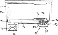
次に第7図は、この発明にかかる第2態様のインクカートリッジと、これが装填される記録装置側の一部構成を断面状態で示したものである。第7図に示すように、記録ヘッド20を構成するヘッドケース20aの下側面には、記録ヘッド20のノズル形成面を構成するノズルプレート20bが配置されており、このノズルプレート20bには複数のノズル開口20cが形成されている。
また、各ノズル開口20cに対応して圧力室が形成されており、その上部に配設された圧電振動子によるアクチュエータ20dが、ヘッドケース20a内に配置されている。そして、ノズル開口20cと圧力室部分から上部に向かってインク連絡流路20eがヘッドケース20a内に形成されている。
前記ヘッドケース20aの上面には、インク導入部を構成する4本の中空状のインク供給針21が直立状態に配置されており、前記ヘッドケース20a内に形成された各インク連絡流路20eは、それぞれ各供給針21内のインク流路に連通されている。なお各供給針21の頂部付近には、インク導入穴21aが形成されており、インクカートリッジからのインクは、このインク導入穴を介して供給針21内に導入され、前記インク連絡流路20eを介して記録ヘッドの圧力室部分に供給されるように構成されている。
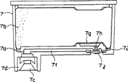
第7図における左端のインク供給針21は、ブラックインクを受けるものであり、このインク供給針21に向かって、その上部からブラックインクカートリッジ7が装着される。このブラックインクカートリッジ7は、その上部の大半がインク貯留室7aになされており、このインク貯留室7aには、多孔質部材(フォーム)7bが収納され、且つ多孔質部材7bにブラックインクが含浸された状態でインクが貯留されている。
また、インク貯留室7aの下側部にはインク供給口7cが形成され、このインク供給口7c内には円環状に形成されたゴム製のパッキング部材7dが嵌め込まれている。そして、インク供給口7cの下端部にはフィルム部材7eが貼着されており、カートリッジの保管中において内部のインク溶媒が揮散しないようにシールされている。
なお、第7図に示す第2形態のインクカートリッジにおいては後で詳細に説明するように、前記したインク貯留室7aからインク供給口7cに向かって水平方向にインク流路7fが形成されており、このインク流路7fの途中に流路制御手段が配置されている。したがってインク貯留室7aからのインクは、インク流路7fを介してインク供給口7cにもたらされる。
前記したブラックインクカートリッジ7は、第7図に示された姿勢のままインク供給針21に向かって押し込むことにより、インク供給口7cに貼着されたフィルム部材7eはインク供給針21によって貫通される。そして、インク供給口7c内に配置されたパッキング部材7dが、インク供給針21の周囲に接合されることで、カートリッジ7は装填状態とされ、ブラックインクが記録ヘッド側に供給できるように構成されている。
また、カラーインクカートリッジ8には、第7図に示すように左から順にシアン、マゼンタ、イエローの各カラーインクを個別に収納するインク貯留室が形成されて、これらが一体に形成されており、それぞれの構成は前記したブラックインクカートリッジ7と同様の構成とされている。したがって、それぞれの構成の詳細な説明は省略する。なお、このカラーインクカートリッジ8においても、第7図に示された姿勢のまま、記録ヘッド20のヘッドケース20a上に樹立された残りの3本のインク供給針21に向かって押し込むことにより、同様に装填状態とされ、3本のインク供給針21を介して、各カラーインクが記録ヘッド側に供給できるように構成されている。
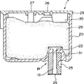
第8図は、第2態様のインクカートリッジにおける第1の実施の形態を示しており、前記したインクカートリッジにおけるインク貯留室のほぼ中央部において切断した状態の縦断面図で示されている。なお、第8図に示したカートリッジは、代表してブラックインクカートリッジ7を示しているが、これは、カラーインクカートリッジにおいても同様の構成になされている。また、以下に示す各図においては、すでに説明した各部に相当する部分を同一符号で示している。
前記したインク貯留室7aの出口部分にはカートリッジフイルタ7gが配置されており、このフイルタ7gの直下には開口7hを形成した弁座部材7iが配置されている。さらに、弁座部材7iに形成された前記開口7hの直下には、流路制御手段を構成するシール部材7jが配置されている。このシール部材7jは、ゴム等の弾性素材により円盤状に形成されており、このシール部材7jの下方より上方に押し上げる駆動力を受けることにより、シール部材7jのほぼ中央部が変形して弁座部材7iに形成された前記開口7hを閉塞することができるように構成されている。
すなわち、図に示した実施の形態においては、前記シール部材7jは、後述するアクチュエータによる駆動力を受けない状態においては、インク流路を開放するように構成されている。そして、弁座部材7iに形成された前記開口7hを介してインク貯留室7aから導出されるインクは、インクカートリッジの下底部近傍に水平方向に形成された前記インク流路7fに導出され、インク流路7fを介して前記したインク供給口7cに向かって導出されるように構成されている。
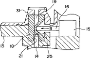
次に第9図は、第2態様のインクカートリッジにおける第2の実施の形態を示しており、同様にインクカートリッジにおけるインク貯留室のほぼ中央部において切断した状態の縦断面図で示されている。この第9図に示されたインクカートリッジ7には、流路制御手段を構成するシール部材7jを、その下方より上方に押し上げる駆動力を与えるアクチュエータ32が配置されている。この実施の形態におけるアクチュエータ32には、電磁駆動機構33が備えられており、例えば電磁駆動機構33に通電されることにより、電磁駆動機構に配置された作動子34が前記シール部材7jを上方に押し上げる駆動力を与えるようになされる。
これにより、弁座部材7iに形成された前記開口7hを閉塞し、結果としてインク流路7fが閉塞されるようになされる。また、電磁駆動機構33への通電を解除することにより、電磁駆動機構33に配置された前記作動子34は、図示せぬバネ部材の付勢力によって第9図に示すように復帰し、弁座部材7iに形成された前記開口7hを開放するように作用する。換言すれば、この第9図に示す実施の形態においては、アクチュエータ32への通電または非通電により、インク流路を開閉することができる流路開閉手段、すなわち電磁弁を構成している。
次に第10図は、第2態様のインクカートリッジにおける第3の実施の形態を示しており、同様にインクカートリッジにおけるインク貯留室のほぼ中央部において切断した状態の縦断面図で示されている。
この第10図に示されたインクカートリッジ7には、流路制御手段を構成するシール部材7jを、その下方より上方に押し上げる駆動力を与えるアクチュエータ32として、偏心カムを備えたカム機構35が採用されている。したがって、このカム機構35を軸35aを中心に回転させることにより、作動子34はシール部材7jを上方に押し上げるように作用する。
これにより、弁座部材7iに形成された前記開口7hを閉塞し、結果としてインク流路7fが閉塞されるようになされる。また、カム機構35を軸35aを中心にさらに同方向に180度回転させるか、元の方向に戻すことにより、作動子34は図示せぬバネ部材の付勢力によって第10図に示すように復帰し、弁座部材7iに形成された前記開口7hを開放するように作用する。
したがって、カム機構35の回転位置に応じて、流路制御手段としてのシール部材7jと、弁座部材7iに形成された前記開口7hとの距離を調整することができる。これにより、インク流路の流路抵抗を変更することができる流路抵抗変更手段を構成している。
なお、第8図ないし第10図に示した第2態様にかかる各インクカートリッジ7は、それぞれブラックインクを貯留したインク貯留室が1のものについて説明したが、複数色のインクをそれぞれ個別に貯留することができる複数のインク貯留室を備えたカラーインクカートリッジ8においても、各インク貯留室から各インク供給口に向かって形成されたそれぞれのインク流路に、それぞれのアクチュエータによる駆動力を個別に受けてインク流路7fを閉塞または流路抵抗を増大させることができる流路制御手段が配置された構成とされる。
以上説明したこの発明にかかる第2態様のインクカートリッジにおいては、インク貯留室7aから流路制御手段を構成する弁座部材7iとシール部材7j、並びにカートリッジの下底部に水平方向に形成されたインク流路7fを介してインク供給口7cにインクを導く比較的複雑な構成になされている。したがって、インクカートリッジの前記した各構成部材の一部に形成されるよどみ部分等に気泡が残留し易いという問題を抱えることになる。
これに対処するためには、インクカートリッジ内に封入されるインクとしては、脱気度の高いものが望まれ、5ppm以下に脱気したインクを封入することで、カートリッジの各構成部材のよどみ部分等に発生し得る気泡を効果的にインク溶媒中に溶解できることが知見された。
また、前記インクカートリッジをメーカ側から出荷する場合、換言すれば、カートリッジの保存状態において、ガスバリア性を有する包装部材によって減圧包装することも効果的である。
第12図は、ガスバリア性を有する包装部材39によって減圧包装した状態を模式的に示したものである。なお、第12図においては包装部材39は原形構造を示しており、したがって、インクカートリッジ7と包装部材39との間には十分な隙間が形成された状態で描かれている。しかしながら、減圧包装した場合には、前記包装部材39は大気圧に押されて収縮し、インクカートリッジ7の表面に、密着された状態になされる。
また、第8図に示したインクカートリッジのように、記録装置側に配置されたアクチュエータによって流路制御手段を構成するシール部材7jが駆動される構成においては、包装部材39によって減圧包装した場合には、脆弱なシール部材7jが包装部材39によって密着状態とされる。このために、カートリッジの取扱時等において、シール部材7jに外力が加わりシール部材7jを破損させるという問題が発生し得る。
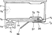
そこで、第11図に示されたように流路制御手段を構成するシール部材7jを、カバー部材によって覆った状態で、第12図に示すように減圧包装することが望ましい。すなわち、第11図に示されたように粘着テープ36の一面に、剛性を有するカバー部材37が貼着されており、このカバー部材37がシール部材7jの露出部分を覆うようにして、前記粘着テープ36がカートリッジの外郭面に貼着されている。
そして、粘着テープ36の端部には、厚紙38が貼着されており、粘着テープ36の端部において、粘着テープ36がカートリッジの外郭面に貼着されるのを阻止するように構成されている。
この構成によって、ユーザが当該カートリッジを使用する際において、前記厚紙38を把持してカートリッジの外郭面から粘着テープ36と共にカバー部材37を容易に剥離することができ、インクカートリッジの交換操作を容易にすることができる。
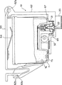
一方、第13図は第8図に示した第1の実施の形態にかかるインクカートリッジを利用する場合において組み合わされる記録装置の構成を示しており、記録装置においてクリーニング動作が実行される状態を示したものである。第8図に示したインクカートリッジを利用する場合においては、記録装置側のキャリッジ上に、カートリッジに配置されたシール部材7jを駆動するためのアクチュエータ32が具備される。この第13図に示すアクチュエータ32は、第9図に示した例と同様に電磁駆動機構33により、電磁弁を構成している。なお、キャリッジ上に搭載されるアクチュエータ32は、第10図に示したように偏心カムを備えたカム機構35を採用することもできる。
ここで、インクカートリッジが記録装置のキャリッジ上に装着された場合、インクカートリッジに形成された前記インク流路7fの流路方向が、キャリッジの移動方向とほぼ直交する関係になされる。
このような関係とすることで、カートリッジ側のインク流路7fに存在するインクが、キャリッジの往復移動に伴う慣性を受ける度合いを低減できるようになされている。
換言すれば、カートリッジに形成された前記インク流路7fの流路方向が、キャリッジの移動方向と同一方向の関係になされた場合には、キャリッジの移動に伴う流路7f内におけるインクの慣性により、記録ヘッドからのインクの吐出安定性を損なうことになる。 第13図における符号9は、前記したキャッピング手段を示している。このキャッピング手段9は、上面が開放されてほぼ方形状に形成されたキャップケース9aと、このキャップケース9a内に収納され、ゴムなどの弾性素材により形成されたキャップ部材9bとが具備され、キャップ部材9bはその上側縁がキャップケース9aよりも若干突出した状態に形成されて、記録ヘッドのノズルプレート20bのシール面を構成している。
そして、キャップ部材9bの内底部には多孔質材料により形成されたインク吸収材9cが収納されている。
前記キャップケース9aはスライダ9d上に保持されており、このスライダ9dは、キャリッジ1がホームポジション側へ移動することに伴って、上昇できるように構成されている。これにより、第13図および第14図に示されたように記録ヘッドのノズル形成面を構成するノズルプレート20bは、キャップ部材9bによって封止されるようになされる。
また、キャリッジがホームポジションから印字領域側に移動した場合には、図示せぬバネ部材の作用によって、前記した動作とは逆にキャッピング手段9は記録ヘッドの封止を解いて降下するように作用する。
また、前記キャップケース9aを貫通するようにして、キャッピング手段の内底部には吸引口が形成されており、この吸引口には負圧発生手段として作用するチューブポンプ10を構成するチューブ10aの一端が接続されている。
ここで、前記したアクチュエータ32を構成する電磁駆動機構33に通電した場合、作動子34が押し上げられてカートリッジ側のシール部材7jは、弁座部材に形成された開口7hを閉塞する。
この状態で前記チューブポンプ10が駆動されると、キャッピング手段9の内部空間に負圧が蓄積される。この負圧はインクカートリッジ側の前記シール部材7jまで作用し、この経路が負圧状態になされる。そして、負圧が十分に蓄積されるとインク供給針21内にとどまる気泡A1は第13図に示すように負圧により膨張する。
この状態で、アクチュエータ32を構成する電磁駆動機構33への通電が遮断されると、第14図に示されたようにカートリッジ側のシール部材7jは、弁座部材に形成された開口7hを解放し、これによって瞬間的にインクの早い流れが発生する。したがって、インク供給針21内の気泡A1は、第14図に示すようにフィルタ部材22を通過し、この際に微小な泡となってキャッピング手段9側に排出される。
次に第15図および第16図は、クリーニング動作の実行により、記録ヘッド20に形成されたインク流路におけるよどみ部分にとどまる気泡をも排出させる様子を示したものであり、第15図および第16図において第13図および第14図と同一部分は同一符号で示している。
記録ヘッド20におけるヘッドケースには、第7図に基づいて説明したように、各色のインクをインク連絡流路20eを介して、圧電振動子によるアクチュエータ20dが配置された圧力室に導入するように構成されている。したがって、これらの構成要素を配置する関係でインクの流れは相当に複雑となる。そして、各所によどみ部分が発生することは免れず、このよどみ部分には、第15図に模式的に示されたように気泡A2がとどまることになる。
このような、よどみ部分にとどまる気泡A2においても、第15図に示すように負圧を加えた場合に、気泡A2を膨張させてよどみ部分から動きやすい状態を与えることができる。そして、第16図に示したようにカートリッジ側のシール部材7jの閉弁状態を開放すると、インクの瞬間的な早い流れによって、前記気泡A2をキャッピング手段9側に排出させることができる。
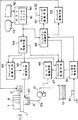
第17図は、前記したクリーニング制御を実行するための制御回路の一例を示したブロック図である。なお、第17図においては、すでに説明した各部に相当する部分を同一符号で示している。第17図に示すように負圧発生手段としての前記チューブポンプ10を構成するチューブ10aの一端は、前記したようにキャッピング手段9に接続されており、その他端は廃液タンク12に接続されている。これにより前記したクリーニング動作によって、キャッピング手段9の内部空間に排出されたインク廃液は、チューブポンプ10を介して廃液タンク12に廃棄することができる。
第17図に示す符号40はホストコンピュータであり、このホストコンピュータ40にはプリンタドライバ41が搭載されている。そして、プリンタドライバ41のユーティリティ上で、入力装置42およびディスプレイ43を利用して、周知の用紙サイズ、モノクロ/カラー印刷の選択、記録モードの選択、フォント等のデータおよび印刷指令等が入力されるように構成されている。
さらに、この実施の形態においては、入力装置42およびディスプレイ43を利用して、後述するようにインクカートリッジに配置されたシール部材7jを駆動するための各アクチュエータ32の動作タイミングが指定できるようにも構成されている。
前記入力装置42における印刷指令の入力により、プリンタドライバ41からは、記録装置に搭載された印刷制御手段44に対して印刷データが送出されるように構成されている。この印刷制御手段44は、前記したホストコンピュータ40から転送される印刷データに基づいてビットマップデータを生成し、このビットマップデータに基づいてヘッド駆動手段45により駆動信号を発生させて、記録ヘッド20からインクを吐出させる機能を備えている。
前記ヘッド駆動手段45は、印刷データに基づく駆動信号の他に、フラッシング制御手段46からのフラッシング指令信号を受けてフラッシング操作のための駆動信号を記録ヘッド20に出力するようにも構成されている。
符号47はクリーニング制御手段であり、このクリーニング制御手段47からの指令によりポンプ駆動手段48が動作して、吸引ポンプ10を駆動制御するように構成されている。また、クリーニング制御手段47には、印刷制御手段44、クリーニングシーケンス制御手段49、およびクリーニング指令検知手段50よりクリーニング指令信号が供給されるように構成されている。
なお、クリーニング指令検知手段50には操作スイッチ51が接続されており、このスイッチ51をユーザが例えばプッシュ操作することにより、前記検知手段50を介してクリーニング制御手段47が起動し、マニュアルによるクリーニング操作が実行されるように構成されている。
また、前記したホストコンピュータ40における入力装置42の操作によっても、印刷制御手段44を介してクリーニング制御手段47が起動し、マニュアルによるクリーニング操作が実行されるように構成されている。
一方、前記クリーニングシーケンス制御手段49は、ホストコンピュータ40およびクリーニング指令検知手段50より指令信号を受けて、アクチュエータ駆動手段52およびキャリッジ駆動手段53に対して制御信号を送出することができるように構成されている。
そして、アクチュエータ駆動手段52は、インクカートリッジ7におけるシール部材7jを駆動する前記したアクチュエータ32に制御信号を送出し、インクカートリッジ7のインク流路7fを閉塞または流路抵抗を増大させる、もしくはその逆の動作がなされるように機能する。
また、キャリッジ駆動手段53はクリーニングシーケンス制御手段49からの指令を受けてキャリッジモータ2を駆動し、記録ヘッド20をキャッピング手段9の直上に移動させて、キャッピング手段9によって記録ヘッドのノズル形成面が封止されるように制御する。
第18図は、以上説明した記録装置の構成によってなされる記録ヘッドのクリーニング動作を示したフローチャートであり、以下、第17図に示すブロック図と共にクリーニング動作のシーケンスを説明する。例えば、記録装置に配置された操作スイッチ51の操作により、またはホストコンピュータ40における入力装置42の操作によってクリーニング動作の指令を受けた場合には、これをクリーニングシーケンス制御手段49が受けて、クリーニングシーケンス制御手段49より各制御信号が出力されることによりクリーニング動作がスタートする。
そして、クリーニングシーケンス制御手段49よりキャリッジ駆動手段53に指令信号が送出され、これによりキャリッジモータ2が駆動され、キャリッジ1をその移動経路に進入したワイピング部材上を移動させることにより、ステップS11に示すように記録ヘッド20のノズル形成面は、ワイピング部材11によりワイピングされる。
続いて、ステップS12に示すようにキャリッジ1は、ホームポジション側に移動し、これに伴ってステップS13に示すように、記録ヘッド20のノズル形成面がキャッピング手段9によってキャッピングされる。
これと同時に、ステップS14に示すように流路制御手段が閉弁される。すなわち、クリーニングシーケンス制御手段49より、アクチュエータ駆動手段52に指令信号が送出され、これにより、前記したアクチュエータ32が駆動されてインクカートリッジ7における流路制御手段を構成するシール部材7jは、インク流路7fを閉塞させるように作用する。
続いて、ステップS15に示すように吸引ポンプ10の駆動が開始される。これは第17図に示すシーケンス制御手段49よりクリーニング制御手段47に制御信号が送出され、クリーニング制御手段47よりポンプ駆動手段48に指令信号が送出されることによってなされる。これにより、吸引ポンプ10が駆動され、キャッピング手段10の内部空間に負圧が印加され、その負圧は序々に増大する。
この状態で、ステップS16に示すように吸引ポンプ10の駆動開始後の所定時間(1)の経過を待ち、キャッピング手段9に与えられる負圧が最大またはその近辺になった状態において、ステップS17に示すように流路制御手段、すなわちインクカートリッジ7におけるシール部材7jが開弁される。この場合、シーケンス制御手段49は前記した所定時間(1)の管理をなすと共に、アクチュエータ32に制御信号を送出することによって、インクカートリッジ7におけるシール部材7jの開弁動作を実行させる。
そして、シール部材7jの開弁後、ステップS18に示すように所定時間(2)の経過が待たれ、ステップS18において所定時間(2)が経過したと判定されるとステップS19に示すように吸引ポンプ10の駆動が停止される。
この場合、シーケンス制御手段49は前記した所定時間(2)の管理をなすと共に、クリーニング制御手段47に制御信号を送出することによって、吸引ポンプ10の駆動動作を停止させるように作用する。
前記ステップS15乃至ステップS19に示した制御シーケンスによってなされるキャッピング手段9に印加される負圧の変化状態が第19図に示されている。すなわち、第19図に示すように吸引ポンプ10の駆動が開始されると、キャッピング手段9の内部空間における負圧は図示のような軌跡をとって急激に上昇する。
そして、所定時間(1)が経過して負圧が最大またはその近辺となった状態において、カートリッジ7におけるシール部材7jが開弁される。これにより前記負圧は急激に開放されて大気圧に近ずく。しかしながら吸引ポンプ10は継続して駆動されているので、負圧は大気圧までは降下せず、所定の負圧の状態に推移する。
そして、カートリッジ7におけるシール部材7jの開弁から所定時間(2)が経過した時に吸引ポンプの駆動が停止され、前記負圧は大気圧まで降下する。
第19図に示した負圧特性で理解できるように、前記した所定時間(1)の経過時点においてシール部材7jが開弁されることにより、インクカートリッジから記録ヘッド7のノズル開口に至るインク流路に、インクの早い流れが発生する。このインクの早い流れによってインク流路内に滞留したり、張り付き状態でとどまる気泡を、膨張させたりインク流路から剥離させることができる。
そして、前記所定時間(2)の期間においても吸引ポンプ10の駆動が継続されインクの吸引が引き続いてなされるため、剥離された気泡をインクの流れにしたがって排出させることができる。
第18図に戻り、ステップS20においては、キャッピング手段9による記録ヘッド20のキャッピングが解除される。そして、ステップS21に示すように吸引ポンプ10が一時的に駆動し停止される。これにより、キャッピング手段9内に排出されたインク廃液は、吸引ポンプ10を介して廃液タンク12に廃棄される。
これに続くステップS22においては、インクの吸引回数が所定回数実行されたか否かが判定され、所定回数に満たない場合には、前記したステップS13乃至ステップS21が繰り返し実行される。そして、ステップS22においてインクの吸引回数が所定回数実行されたと判定されると、ステップS23に示すようにワイピング動作が実行され、記録ヘッドのノズル形成面に付着しているインクがワイピング部材11によって払拭される。
そして、ステップS24に示すように、記録ヘッド20はキャッピング手段9によって封止され、印刷データの到来を待つ状態とされる。なお、前記したステップS22においては、インクの吸引回数が所定回数実行されたか否かを判定しているが、1回の吸引動作により十分に回復効果が得られるのであれば、このステップS22の判定ステップは不要である。
以上説明したクリーニング動作は、記録装置に配置された操作スイッチ51の操作により、またはホストコンピュータ40における入力装置42の操作によって実行されるマニュアルクリーニング動作について説明しているが、例えば記録装置に初めてインクを充填する初期充填動作において、前記したクリーニング動作が実行されるようにプログラミングされていることは効果的である。
このように、記録装置に初めてインクを充填する初期充填動作においては、前記したようにインク導入針内、および記録ヘッドのインク流路内に多くの気泡が残留し易い。
したがって、初めて記録ヘッドの流路内にインクを充填する場合には、これに用いられるインクの脱気度が高いことが望ましい。しかし、インクの脱気度を高めるには限界があると共に、初期充填後の流路内のインクは空気層と置き換えられながら充填されるため、脱気度が急激に低下する。
したがって、このような観点から初期充填動作時において気泡を確実に排出させることはきわめて重要であり、これにより安定した印字動作を保証することに寄与できる。
一方、ユーザによってなされるマニュアルクリーニングの指令が、所定の印字量の範囲内において再びなされた場合に、前記したクリーニング動作が実行されるようにプログラミングされていることも効果的である。
このように、所定の印字量の範囲内において再びマニュアルクリーニングの指令がなされるという場合は、ユーザが印字不良を認識して再度クリーニング動作を実行されるケースが多く、このような場合は、例えば記録ヘッドの流路内に比較的大きな気泡が流れ込み、インクの充填性に障害を与えている状態に陥っている可能性がある。
第20図は、前記したようにマニュアルクリーニングの指令が、所定の印字量の範囲内において再びなされた場合に、前記したクリーニング動作が実行される制御シーケンスの一例を示している。
第20図に示した動作シーケンスの特徴とするところは、前回のクリーニング動作の実行後の印字量に応じてステップS36において、どのモードのクリーニングを実行させるかを判断し管理するCL2カウンタ(KK)を備えており、3つのクリーニングモードのいずれかを選択するように制御される。
そして、CL2カウンタ(KK)の値を置き換えて、各クリーニングモードのパラメータをセットし、ステップS41において、それに応じたクリーニング動作が実行されるようになされる。
この第20図に示した動作シーケンスは、記録装置に配置された操作スイッチ51の操作により、またはホストコンピュータ40における入力装置42の操作によって実行されるマニュアルによるクリーニング動作指令が発せられた時に起動される。
まず、ステップS31においては、例えば印刷制御手段44に格納されている印字履歴が参照され、記録装置の動作電源がオンされて以来、1パス以上の印字がなされたか否かが判定される。このステップにおいて、1パス以上の印字がなされていない(No)と判定されると、ステップS35に移行し、CL1モードのパラメータがセットされる。
このCL1モードは、クリーニングの種類を示すものであり、このCL1モードが最も吸引量が少ないモードである。また、後述するCL2モード、およびCL3モードになるにしたがって、吸引量が多くなされる。この場合、吸引量に変えて、吸引速度を変更するようにしてもよい。
このように吸引量を変更させるのは、例えば軽い印字障害の状態においても一律に大量のインクを消費させるのを避ける意味合いがあり、これにより無闇にインクを浪費するのが避けられる。
そして、ステップS41に移りクリーニング動作が実行される。すなわち、記録装置の動作電源がオンされた直後において、クリーニング動作の指示を受けた場合には、吸引量が最も少ないモードであるこのCL1モードのクリーニング動作が実行される。
前記ステップS31において、1パス以上の印字がなされている(Yes)と判定されると、ステップS32に移り、前回のクリーニング動作後から1パス以上の印字がなされたか否かが判定される。ここで、1パス以上の印字がなされていない(No)と判定されると、前記と同様にステップS35に進みCL1モードによるクリーニングが実行される。
また、ステップS32において前回のクリーニング動作後から1パス以上の印字がなされた(Yes)と判定された場合には、ステップS33において前回のクリーニング動作後からの印字量が5ページ以下であるか否かが判定される。
ここで、前回のクリーニング動作実行後における印字ページ数が5ページ以下ではない(No)と判定されると、ステップS34に移行し、CL2カウンタのKKを“1”にセットし、前記したステップS35に移行する。ここで、前記CL2カウンタのKKは、クリーニング選択動作においてクリーニングモードの選択順を次のとおりに実行させるカウンタである。
すなわち、先ずKK=1に定義し直した後、CL1モードをセットし、第1クリーニングモード(CL1)を実行するようにしたとする。続いてクリーニング動作に入る場合にはKK=1と定義されているので、KK=2に定義し直した後、CL2モードをセットし、第2クリーニングモード(CL2)を実行するようになされる。
同様に次にクリーニング動作に入る場合にはKK=2と定義されているので、KK=0に定義し直した後、CL3モードをセットし、第3クリーニングモード(CL3)を実行するようになされる。このように、CL1→CL2→CL3の繰り返しがなされ、CL1→CL2→CL3となるにしたがって吸引量が増大され、より強力なクリーニング動作を実行することになる。
換言すればクリーニング動作が続けて実行されるということは、印字状態がなかなか正常に復帰しないということとなり、より強力なクリーニング動作にシフトさせる必要が生じ、前記したような制御がなされるように設定されている。
前記したように、ステップS33において前回のクリーニング動作実行後における印字ページ数が5ページ以下ではない(No)と判定される場合において、再びユーザによりクリーニング指令が入力される場合は、先のクリーニング動作で、印字状態の回復が成し遂げたものの、新たな不具合の発生によりクリーニング動作が必要になったものと判断してCL2のカウンタKKを“1”にセットし、CL1に設定するようになされている。
一方、前記ステップS33において、前回のクリーニング動作実行後における印字ページ数が5ページ以下である(Yes)と判定された場合においては、ステップS36においてCL2カウンタの値が検証される。
ここで、KK=3である場合には、前記したステップS34に移行し、KK=1である場合には、ステップS37に移行し、CL2カウンタのKKを“2”にセットし、次に続くステップS38において、CL2モードのパラメータをセットさせる。
したがって、ステップS38に続くステップS41におけるクリーニング動作は、ステップS38においてセットされた第2クリーニングモード(CL2)が実行される。そして、前記ステップS36においてKK=2であると判定されると、ステップS39に移行し、CL2カウンタのKKを“3”にセットし、次に続くステップS40において、CL3モードのパラメータをセットさせる。
したがって、ステップS40に続くステップS41におけるクリーニング動作は、ステップS40においてセットされた第3クリーニングモード(CL3)が実行される。
第20図に示した動作シーケンスによると、マニュアルによるクリーニング動作の指令があった場合、前回のクリーニング動作後の印字量に応じてクリーニング動作が選択されるようになされる。これによって、状態に応じた最適なクリーニング動作がなされ、またインクの浪費を抑えることができる。
以上説明したクリーニング動作は、ブラックインクカートリッジにおける流路制御手段としてのシール部材、およびカラーインクカートリッジのそれぞれ3つのシール部材が同時に閉弁および開弁される場合を前提にしている。
すなわち、キャッピング手段によって記録ヘッドのノズル形成面を封止し、インクカートリッジに備えられたシール部材を閉塞させた状態で吸引ポンプによる負圧をキャッピング手段内に加えて負圧を蓄積させる負圧蓄積ステップと、キャッピング手段内の負圧が蓄積された状態で、インクカートリッジに備えられたシール部材を開放させる負圧解除ステップとが、それぞれ同時になされる前提で説明している。
ところで、色材濃度が高いインク、例えばブラックインクは他の色のインクに比較してクリーニング動作による回復性が低いという問題を有している。したがって、前記したような制御がなされた場合、カラーインクが扱われるノズルが先行して回復し、カラーインクが益々キャッピング手段内に排出されて、ブラックインクを扱うノズルに対する負圧が作用しにくくなるという現象が発生する。
そこで、このような問題に対処するために、各アクチュエータ32によって流路制御手段としてのそれぞれのシール部材を、独立して制御する形態を採用することが好ましい。
この場合、負圧蓄積ステップと前記負圧解除ステップとが、特定の流路におけるシール部材のみを駆動させるように制御することができ、また、負圧蓄積ステップは同時に、負圧解除ステップのみが特定の流路においてなされるように制御することもできる。これにより、特定のインクが貯留されたカートリッジのみに負圧を作用させてクリーニング動作を実行することができる。
例えば、前記したブラックインクカートリッジおよびカラーインクカートリッジのそれぞれのインク流路に備えられた各シール部材を、同時に閉弁制御して負圧を加えると共に、ブラックインクカートリッジにおけるシール部材を開弁制御することで、色材濃度が高いブラックインクのノズルに対してのみ、負圧によりインクを排出させることができる。これにより、ブラックインクを扱うノズルに対して集中的にクリーニング動作を実行させることができる。
前記した特定のインクを扱うノズルに対するクリーニング動作の実行は、記録装置に搭載された制御プログラムによって実行されるようになさていることが好ましい。さらにこの場合、記録装置における印字終了後の放置時間に応じて、特定のインクを扱うノズルに対するクリーニング動作が実行されるようにプログラムされていることが望ましい。
そして、前記した特定のインクに対応するクリーニング動作は、好ましくは、ホストコンピュータに搭載されたプリンタドライバのユーティリティ上において、または記録装置本体に配置された図示せぬ操作ボタン等で指定することができるように構成し、この指定情報に基づいて特定のインクに対応してクリーニング動作が実行されるように構成されていることが望ましい。
以上の説明は、インクカートリッジのインク流路にそれぞれ配置された流路制御手段を開閉弁制御することで、効率的なクリーニング動作を実行させる点に主体をおいて説明したが、前記流路制御手段を個別に開閉弁制御することができる構成を利用して、次に示すような制御も実現させることができる。
例えば、記録装置には、これに搭載されたインクカートリッジにおけるインクエンド状態を検出するインクエンド検出手段が具備されており、少なくとも、負圧発生手段による負圧をキャッピング手段に加える状態においては、インクエンド状態を検出したインク流路7fに備えられた前記流路制御手段、すなわち、シール部材7jを閉塞状態に保持するように制御すると、クリーニング動作によるインクの排出によって、インク室内のインクを完全に空状態にするのを防止することができる。
すなわち、実施の形態に示したように、各インク室7aに多孔質部材(フォーム)7bが収納され、この多孔質部材7bにインクが含浸された状態で貯留されている構成のカートリッジにおいては、インクが完全に空状態となった場合には、大気連通孔から大気が流入する結果、負圧を加えることは不可能となる。
また、流路内が空状態となることで、その後の気泡の排出性が損なわれることになる。したがって、インクエンド状態を検出した場合においては、それに対応するシール部材7jを個別に閉塞状態に保持するように制御することで、前記したような問題の発生を防止することができる。
前記したインクエンド検出手段としては、実施の形態のように多孔質部材7bにインクが含浸された状態で貯留されているカートリッジ(フォームカートリッジ)においては、ソフトインクエンド検出手段を利用することができる。
このソフトインクエンド検出手段は、印刷動作およびフラッシング動作において、記録ヘッドから吐出されたインク滴を計数することによるインクの使用量、また前記したクリーニング動作によって消費したインク量も演算して、これらを合算することで、インクエンド状態を認識するようになされる。
また、実施の形態として示していないが、可撓性素材により形成されたインクパック内にインクを封入して貯留する構成のインクカートリッジにおいては、前記インクパックの物理的な変化を機械的に検出することで、インクエンド状態と判定するハードインクエンド検出手段を用いることができる。このハードインクエンド検出手段によりインクエンドを検出した際に、前記した制御を実行させることで、インクパック形式のカートリッジを利用した記録装置においても、同様の作用効果を得ることができる。
さらに、実施の形態として示すフォームカートリッジにおいて、複数色を一体に形成した例えばカラーインクカートリッジにおいては、そのうちの一色でもインクエンド状態となると、他のインクは使用せずに当該カートリッジを交換させる運用がなされていたが、前記したように個別に流路制御手段、すなわち、シール部材7jを備えた構成とした場合、インクエンド状態に達していない他のインクを有効に利用するような運用も実行することができる。
すなわち、印刷動作を実行するに際しては、インクエンド状態を検出したインク流路に備えられた前記流路制御手段を閉塞状態に保持し、インクエンド状態以外のインクを用いることができる。
この場合、イエローインクのみにおいては、識別が困難であるため、インクエンド状態以外のインクのうち、イエローインクを除いた他のインクのうち、最もインク残量の多いインクによって印刷動作を実行するように構成することが好ましい。
さらに、前記したようにインクエンド状態以外のインクを用いて印刷動作を実行する場合においては、ホストコンピュータに搭載されたプリンタドライバのユーティリティ上において、インクエンド以外の他のインクで印刷することを報知するように構成することが望ましい。
また、インクエンド状態以外のインクを用いて印刷動作を実行するに際しては、ホストコンピュータに搭載されたプリンタドライバのユーティリティ上において、インクエンド以外の他のインクで印刷を実行するか否かの判断を要求する報知を行なうように構成した記録装置も好適に利用することができる。
例えば、ブラックインクカートリッジがインクエンド状態となった場合には、シアン、マゼンタ、およびイエローの各インクを用いてコンポジットブラックで印刷を行なうことも可能であり、ユーザは前記した判断要求を認識して、コンポジットブラックによる印刷を指令することも可能となる。
以上の説明で明らかなように、この発明にかかる第2態様のインクカートリッジによると、インク貯留室からインク供給口に向かって形成されたインク流路に、アクチュエータによる駆動力を受けてインク流路を閉塞または流路抵抗を増大させることができる流路制御手段を配置したので、記録装置側またはカートリッジ側に配置されたアクチュエータによって、インクカートリッジに配置された流路制御手段を開閉または流路抵抗を変更することができる。
したがって、キャッピング手段の内部空間に負圧を蓄積した状態で流路制御手段を開放することで、例えばインク供給針内のフィルタ部材上に滞留する気泡を効果的に排出させることができる。
また、この発明にかかるクリーニング制御方法を採用したインクジェット式記録装置によると、前記した第2態様のインクカートリッジを利用することで、効果的なクリーニング動作を実行させることができると共に、各色のインクに対応して個別に各流路制御手段が制御できるので、特定のインクに対応して効率的にクリーニング動作を実行させることができる。
次に、この発明にかかる第3態様のインクカートリッジおよびこれを利用する記録装置について説明する。第21図はキャリッジに配置されたカートリッジホルダと、これに装填されたこの発明にかかる第3態様のインクカートリッジの構成を一部を破断した状態で示したものである。
まず、カートリッジホルダ61は、上部が開放されてインクカートリッジを着脱することができる開口を備えたホルダケース62と、このホルダケースの一端部にヒンジ機構62aを介して前記開口を開閉することができる蓋体63が具備されている。
この蓋体63の自由端側端部はU字状に形成されて、ホルダケース側に形成された係合部62bに係止されるフック部63aが形成され、両者の係合により蓋体63はカートリッジホルダを閉じた状態を維持できるように構成されている。
そして、前記蓋体62の裏面には、ホルダ内に装填された後述するインクカートリッジを下底部の方向に付勢するリーフ状のバネ部材64が取り付けられている。またカートリッジホルダ61を構成する前記ホルダケース62の下側面には、記録ヘッド20が取り付けられている。
そして、装填されたインクカートリッジからこの記録ヘッド20に対してインクを供給することができるインク導入部としての中空状のインク供給針21がホルダケースの下底部から上方に向かって配置されている。
一方、前記カートリッジホルダ61内に装着されたインクカートリッジは、例えば前記したブラックインクカートリッジ7を示している。このインクカートリッジ7には前記した第2態様のインクカートリッジと同様に、インク貯留室7aが形成され、その内部に多孔質部材7bが収納されて、この多孔質部材7bにインクを含浸した状態で保持している。
なお、前記したカラーインクカートリッジ8においては、イエロー、マゼンタ、シアンの各インクを貯留できる独立したインク貯留室が並列状態に備えられている点で、ブラックインクカートリッジ7と相違しているが、後述する各構成はほぼ同一になされている。
前記カートリッジ7の下底部には、インク供給口65が形成されている。そして、このインク供給口65に接合される、インク供給針21によって、カートリッジより引き出されたインクはフィルタ部材22を介して記録ヘッド20に供給されるように構成されている。また、インク供給口65内には、後で詳細に説明するようにインク供給針21による相対的な押圧力を受けて開弁され、インク貯留室からのインクの供給を可能にする流路制御手段67が収納されている。
前記インクカートリッジ7は、カートリッジホルダ62内に収納された第21図に示す状態において、前記したバネ部材64の作用によって下底部の方向に付勢されており、一方、ホルダ62の下底部にはアクチェータとしての偏心カム機構32が配置されている。したがって、前記偏心カム機構32の回転駆動によって、カートリッジ7はホルダ62内を上下方向に移動することができるように構成されている。
第22図ないし第24図は、前記したカートリッジホルダの下底部の構成と、これに装填されたインクカートリッジの下底部の構成を拡大して示したものである。第22図はインクカートリッジがカートリッジホルダに対して装着される直前の状態を示しており、第23図はカートリッジがカートリッジホルダに対して装着され、記録ヘッド側にインクが供給できる状態を示しており、さらに第24図はカートリッジがカートリッジホルダに装着された状態で、前記偏心カム機構32の回転駆動によって、インク貯留室からのインクの供給が停止された(流路制御手段67が閉弁された)状態を示している。
なお、第22図ないし第24図においては、すでに説明した各部に相当する部分は同一符号で示している。
第22図ないし第24図に示されたように、インクカートリッジ7におけるインク供給口65は円筒状の容積が形成されており、その出口開口部分には円筒状に形成された第1パッキング部材71が嵌め込まれている。また、インク供給口65の最奥部にも円筒状に形成された第2パッキング部材72が嵌め込まれている。
前記した流路制御手段67は、円盤状部材67aと、この円盤状部材の移動をガイドする軸部材67bとにより構成されており、この軸部材67bを受ける軸受体73が、前記第2パッキング部材72の内部空間に突出するように形成されている。これにより、流路制御手段67を構成する前記円盤状部材67aが、前記軸部材67bの軸方向に移動できるように配置されている。
また、前記円盤状部材67aとインク供給口65における最奥部との間には、前記軸部材67bを捲装するようにしてコイル状のバネ部材74が配置されており、このバネ部材74の付勢力により、前記円盤状部材67aはインク供給口65の出口方向に付勢されている。
この構成によって第22図に示すように、カートリッジがカートリッジホルダ61に装着される以前においては、円盤状部材67aの一面が前記第1パッキング部材71に接合し、閉弁状態を保持することができるように構成されている。
前記した作用によって、インクカートリッジは、記録装置への非装填状態においては、インク供給口65に配置された前記円盤状部材67aによって、インク供給口は閉弁状態とされる。したがって、例えばカートリッジの使用途中で記録装置から取り外した場合であっても、カートリッジからインクが漏出したり、またはインクカートリッジ内に空気が侵入するという問題を回避することができる。それ故、当該カートリッジを再び記録装置に装填して利用することが可能となる。
一方、インクカートリッジがカートリッジホルダ61内に装着された場合には、第23図に示されたようにインクカートリッジに形成された前記インク供給口65には、カートリッジホルダに配置された前記インク供給針21が相対的に進入する。
このためにインク供給口65に配置された円盤状部材67aはインク供給針21の先端部によって押し上げられ、前記円盤状部材67aと第1パッキング部材71との接合が解かれて開弁状態とされる。すなわち、流路制御手段67が第23図に示した第1の位置に移動されることで開弁状態になされる。
これと同時に、インク供給針21は円筒状に形成された第1パッキング部材71の内周面に接合して、カートリッジのインク供給口65との間で液密状態が保持される。
第23図に示した状態は、アクチェータとしての偏心カム機構32は、軸芯32aに対して遠い位置にあるカム面が、上部に向かった状態とされており、したがってインクカートリッジは、このカム面に当接されて第23図に示した状態に保持される。
この状態においては、円盤状部材67aが第1パッキング部材71と第2パッキング部材72との中間点に位置している。したがって、当該カートリッジのインク貯留室より、前記軸受体73に形成されたインク流通穴73aを介してインク供給針21側にインクが導出され、インク供給針21を介して記録ヘッド20側にインクが供給される。したがって、この状態において記録装置の印字動作を実行することができる。
第23図に示した状態で、アクチェータとしての前記偏心カム機構32がほぼ90度回転駆動されると、第24図に示されたようにインクカートリッジ7は、カートリッジホルダ61の蓋体63に配置された前記バネ部材64の付勢力により、さらにカートリッジホルダの下底部の方向に移動する。
このために、第1パッキング部材71の内周面に接合している前記インク供給針21は、さらにインク供給口65の奥側に相対的に進入する。したがって、円盤状部材67aはインク供給針21の先端部によってさらに押し上げられ、前記円盤状部材67aの裏面が第2パッキング部材72に接合し閉弁状態とする。これにより、インク貯留室からのインクの供給は停止される。すなわち、流路制御手段67が第24図に示した第2の位置に移動されることで閉弁状態になされる。
したがって、以上の構成によると、カートリッジホルダの下底部に配置された前記偏心カム機構32を、90度の範囲で往復回転駆動させることで、第23図に示す開弁状態および第24図に示す閉弁状態に制御することができる。
以下の説明は、前記した作用によってもたらされる開閉弁機能を利用して、効果的にクリーニング動作を実行するようにした形態を示している。
すなわち、クリーニング動作は、第24図に示したように円盤状部材67aの裏面が第2パッキング部材72に接合して閉弁状態とされた状態において実行される。そして、第1図に示すキャリッジ1はホームポジションに移動され、これにより記録ヘッドのノズル形成面は前記キャッピング手段9によって封止される。
この状態で前記吸引ポンプ10が駆動されると、キャッピング手段9の内部空間に負圧が蓄積される。このように、負圧が十分に蓄積されるとインク供給針21内にとどまる気泡は負圧により膨張する。
この状態で、前記偏心カム機構32を90度回転駆動させると、第23図に示されたように開弁状態となり、これによって瞬間的にインクの早い流れが発生する。したがって、インク供給針21内の気泡は、フィルタ部材22側に一気に引き寄せられ、フィルタ部材22を通過してキャッピング手段9側に排出される。なお、この作用によって、例えば記録ヘッド20におけるヘッドケースに形成されたインク流路におけるよどみ部分にとどまる気泡をも効果的に排出させることができる。
前記した負圧の蓄積によるクリーニング動作の実行は、前記した第17図による制御回路によって、同様に実現させることができる。すなわち、第17図に示したアクチェータ駆動手段52は、前記したアクチェータとしての偏心カム機構32を回転駆動させて、カートリッジ内の流路制御手段を構成する前記円盤状部材67aを相対移動させるようになされ、これにより、開弁または閉弁状態が設定できるように作用する。
そして、この第17図による制御回路によってなされる記録ヘッドのクリーニング動作についても、第18図に示した動作シーケンスにしたがって実行される。
例えば、記録装置に配置された操作スイッチ51の操作により、またはホストコンピュータ40における入力装置42の操作によるクリーニング動作の指令を受けた場合には、これをクリーニングシーケンス制御手段49が受けて、クリーニングシーケンス制御手段49より各制御信号が出力されることによりクリーニング動作がスタートする。
そして、クリーニングシーケンス制御手段49よりキャリッジ駆動手段53に指令信号が送出されることによりキャリッジモータ2が駆動され、キャリッジ1はその移動経路に進入したワイピング部材上を通過させることにより、ステップS11に示すように記録ヘッド20のノズル形成面は、ワイピング部材11によりワイピングされる。
続いて、ステップS12に示すようにキャリッジ1は、なおもホームポジション側に移動し、これに伴ってステップS13に示すように、記録ヘッド20のノズル形成面がキャッピング手段9によってキャッピングされる。
これと同時に、ステップS14に示すように流路制御手段が閉弁される。すなわち、クリーニングシーケンス制御手段49より、アクチェータ駆動手段52に指令信号が送出され、前記したアクチェータとしての偏心カム32が駆動される。その結果、インクカートリッジ7における流路制御手段を構成する円盤状部材67aは、第2パッキング部材72を封止し閉弁状態とする。
続いて、ステップS15に示すように吸引ポンプ10の駆動が開始される。これは第17図に示すシーケンス制御手段49よりクリーニング制御手段47に制御信号が送出され、クリーニング制御手段47よりポンプ駆動手段48に指令信号が送出されることによってなされる。これにより、吸引ポンプ10が駆動され、キャッピング手段9の内部空間に負圧が印加され、その負圧は蓄積されて増大する。
この状態で、ステップS16に示すように吸引ポンプ10の駆動開始後の所定時間(1)の経過を待ち、キャッピング手段9に与えられる負圧が最大またはその近辺に蓄積された状態において、ステップS17に示すように流路制御手段、すなわちインクカートリッジ7における円盤状部材67aが開弁される。
この場合、シーケンス制御手段49は前記した所定時間(1)の管理をなすと共に、アクチェータ32に制御信号を送出することによって、インクカートリッジ7における円盤状部材67aの開弁動作を実行させる。
そして、円盤状部材67aの開弁後、ステップS18に示すように所定時間(2)の経過が待たれ、ステップS18において所定時間(2)が経過したと判定されるとステップS19に示すように吸引ポンプ10の駆動が停止される。この場合、シーケンス制御手段49は前記した所定時間(2)の管理をなすと共に、クリーニング制御手段47に制御信号を送出することによって、吸引ポンプ10の駆動動作を停止させるように作用する。
前記ステップS15乃至ステップS19に示した制御シーケンスによってなされるキャッピング手段9に印加される負圧の変化状態も、前記した第19図と同様に表すことができる。すなわち、第19図に示すように吸引ポンプ10の駆動が開始されると、キャッピング手段9の内部空間における負圧は比較的急峻に上昇する。そして所定時間(1)が経過して負圧が最大またはその近辺となった状態において、カートリッジ7における円盤状部材67aが開弁される。
これにより前記負圧は急激に開放されて大気圧に近ずく。しかしながら吸引ポンプ10は継続して駆動されているので、負圧は大気圧までは上昇せず、所定の負圧の状態に推移する。そして、カートリッジ7における円盤状部材67aの開弁から所定時間(2)が経過した時に吸引ポンプの駆動が停止され、前記負圧は大気圧まで上昇する。
第19図に示した負圧特性で理解できるように、前記した所定時間(1)の経過時点において円盤状部材67aが開弁されることにより、インクカートリッジから記録ヘッド7のノズル開口に至るインク流路に、インクの早い流れが発生する。このインクの早い流れによってインク流路内に滞留している気泡を効果的に動かすことができる。
そして、前記所定時間(2)の期間においても吸引ポンプ10の駆動が継続されインクの吸引が引き続いてなされるため、前記気泡をインクの流れにしたがって排出させることができる。
第18図に戻り、ステップS20においては、キャッピング手段9による記録ヘッド20のキャッピングが解除される。そして、ステップS21に示すように吸引ポンプ10が一時的に駆動し停止される。これにより、キャッピング手段9内に排出されたインク廃液は、吸引ポンプ10を介して廃液タンク12に廃棄される。
これに続くステップS22においては、インクの吸引回数が所定回数実行されたか否かが判定され、所定回数に満たない場合には、前記したステップS13乃至ステップS21が繰り返し実行される。そして、ステップS22においてインクの吸引回数が所定回数実行されたと判定されると、ステップS23に示すようにワイピング動作が実行され、記録ヘッドのノズル形成面に付着しているインクがワイピング部材11によって払拭される。そして、ステップS24に示すように、記録ヘッド20はキャッピング手段9によって封止され、印刷データの到来を待つ状態とされる。
以上説明した第3態様のカートリッジを利用したクリーニング動作は、記録装置に配置された操作スイッチ51の操作により、またはホストコンピュータ40における入力装置42の操作によって実行されるマニュアルクリーニング動作について説明しているが、例えば記録装置に初めてインクを充填する初期充填動作において、前記したクリーニング動作が実行されるようにプログラミングされていることは効果的である。
このように、記録装置に初めてインクを充填する初期充填動作においては、インク供給針内、および記録ヘッドのインク流路内に多くの気泡が残留し易い。
したがって、初めて記録ヘッドの流路内にインクを充填するには、インクの脱気度が高いことが望ましい。しかしながら、インクの脱気度をある程度以上に高めるには限界があると共に、初期充填後の流路内のインクは空気層と置き換えられながら充填されるため、脱気度が急激に低下する。
このような観点から初期充填動作時において気泡を確実に排出させることはきわめて重要であり、これにより安定した印字動作を保証することに寄与できる。
一方、第2態様のカートリッジを利用した場合と同様に、ユーザによってなされるマニュアルクリーニングの指令が、所定の印字量の範囲内において再びなされた場合に、前記したクリーニング動作が実行されるようにプログラミングされていることも効果的である。
このように、所定の印字量の範囲内において再びマニュアルクリーニングの指令がなされるという場合は、ユーザが印字不良を認識して再度クリーニング動作を実行されるケースが多く、このような場合は、例えば記録ヘッドの流路内に比較的大きな気泡が流れ込み、インクの充填性に障害を与えている状態に陥っている可能性がある。
そこで、前記したようにマニュアルクリーニングの指令が、所定の印字量の範囲内において再びなされた場合に、前記したクリーニング動作が実行される制御シーケンスとして第20図に示した場合と同様の制御ルーチンを実行させるのも効果的である。なお、第20図に示した制御ルーチンは、第2態様のインクカートリッジを利用した場合の採用例として既に説明しており、したがって重複する説明は割愛する。
以上説明したクリーニング動作は、例えばブラックインクカートリッジおよびカラーインクカートリッジにおけるそれぞれの流路制御手段としての円盤状部材67aが同時に閉弁および開弁される場合を前提にしている。
すなわち、キャッピング手段によって記録ヘッドのノズル形成面を封止し、各インクカートリッジに備えられた円盤状部材67aを閉弁させた状態で吸引ポンプによる負圧をキャッピング手段内に加えて負圧を蓄積させる負圧蓄積ステップと、キャッピング手段内の負圧が蓄積された状態で、各インクカートリッジに備えられた円盤状部材67aを開弁させる負圧解除ステップとが、それぞれ同時になされる前提で説明している。
ところで、色材濃度が高いインク、例えばブラックインクは他の色のインクに比較してクリーニング動作による回復性が低いという問題を有している。したがって、前記したような制御がなされた場合、カラーインクが扱われるノズルが先行して回復し、カラーインクが益々キャッピング手段内に排出されて、ブラックインクを扱うノズルに対する負圧が作用しにくくなるという現象が発生する。
そこで、このような問題に対処するために、各アクチェータ32によって流路制御手段としてのそれぞれの円盤状部材67aをインクカートリッジ毎に独立して制御する形態を採用することが好ましい。
この場合、負圧蓄積ステップと前記負圧解除ステップとが、特定のインクカートリッジにおける円盤状部材67aのみを駆動させるように制御することができ、また、負圧蓄積ステップは同時に、または負圧解除ステップのみが特定の流路においてなされるように制御することもできる。
これにより、特定のインクが貯留されたインクカートリッジのみに負圧を作用させてクリーニング動作を実行することができる。
例えば、前記したブラックインクカートリッジおよびカラーインクカートリッジのそれぞれのインク供給口に備えられた各円盤状部材67aを、同時に閉弁制御して負圧を加えると共に、ブラックインクカートリッジにおける円盤状部材67aを開弁制御することで、色材濃度が高いブラックインクのノズルに対してのみ、負圧によりインクを排出させることができ、これによりブラックインクを扱うノズルに対して集中的にクリーニング動作を実行させることができる。
前記した特定のインクを扱うノズルに対するクリーニング動作の実行は、記録装置に搭載された制御プログラムによって実行されるようになさていることが好ましい。さらにこの場合、記録装置における印字終了後の放置時間に応じて、特定のインクを扱うノズルに対するクリーニング動作が実行されるようにプログラムされていることが望ましい。
そして、前記した特定のインクに対応するクリーニング動作は、好ましくは、ホストコンピュータに搭載されたプリンタドライバ上のユーティリティにおいて、または記録装置本体に配置された図示せぬ操作ボタン等で指定することができるように構成し、この指定情報に基づいて特定のインクカートリッジに対応してクリーニング動作が実行されるように構成されていることが望ましい。
なお、前記した実施の形態においては、カートリッジホルダに配置されたアクチェータとしての偏心カム機構32を電気的に制御して回転駆動させることを前提にして説明しているが、この偏心カム機構32は、例えば手動で駆動させることもできる。また、前記アクチェータを電気的に制御する場合においては、実施の形態のように偏心カム機構を用いずに、例えば電磁プランジャーなどを用いることもできる。
以上の説明で明らかなように、この発明にかかる第3態様のインクカートリッジによると、インク供給口に配置された流路制御手段は、記録装置に装填された状態において記録装置側のインク導入部の押圧力を受けて第1の位置に移動して開弁され、また第2の位置に移動して閉弁されるので、インク導入部の押圧力に応じて流路制御手段を開閉させることができる。したがって、キャッピング手段の内部空間に負圧を蓄積した状態で流路制御手段を開放することで、例えばインク供給針内にとどまる気泡を効果的に排出させることができる。
また、この発明にかかるクリーニング制御方法を採用したインクジェット式記録装置によると、前記した第3態様のインクカートリッジを利用することで、効果的なクリーニング動作を実行させることができると共に、各カートリッジ毎に個別に各流路制御手段が制御することができるので、特定のインクに対応して効率的にクリーニング動作を実行させることができる。Technical field
The present invention relates to an ink jet recording apparatus that includes a recording head that moves in the width direction of a recording sheet, for example, and prints an image on the recording sheet by ejecting ink droplets toward the recording sheet based on print data. Specifically, an ink cartridge capable of effectively executing a cleaning process for recovering the printing function of the recording head by sucking ink from the nozzle opening of the recording head, an ink jet recording apparatus using the same, and a recording head in the apparatus The present invention relates to a cleaning control method.
Background art
The ink jet recording apparatus includes an ink jet recording head that receives ink supplied from an ink cartridge, and a paper feeding unit that moves the recording paper relative to the recording head, and records the recording head mounted on the carriage. Recording is performed by ejecting ink droplets while moving in the width direction of the paper.
A recording head capable of ejecting black ink and yellow, cyan, and magenta color inks is mounted on the carriage, and full color printing is possible by changing the ejection ratio of each ink as well as text printing with black ink. It is possible.
The recording head described above performs printing by ejecting ink pressurized in the pressure generation chamber as ink droplets from a nozzle onto a recording sheet. For example, an increase in ink viscosity caused by evaporation of a solvent from the nozzle opening, There is a problem in that printing failure occurs due to solidification of dust, adhesion of dust, and mixing of bubbles.
For this reason, when the nozzle opening is clogged or when the ink cartridge is replaced, the nozzle forming surface of the recording head is sealed by the capping means, and the ink is discharged from the nozzle opening by the negative pressure from the suction pump. The function of eliminating clogging due to ink solidification at the nozzle opening and the like, and ink ejection failure due to mixing of air bubbles into the ink flow path, is provided, which is called a cleaning operation. .
When performing this cleaning operation, for example, it is effective to generate an ink flow as early as possible in the ink flow path from the ink cartridge to the nozzle opening of the recording head. Bubbles present in the flow path can also be discharged.
However, in order to increase the ink flow rate during the cleaning operation, it is necessary to increase the capacity of the suction pump in order to obtain a large negative pressure. For this purpose, along with the increase in size of the pump, it is necessary to use a large motor for driving the pump, which inevitably increases the cost and the size of the entire apparatus.
Furthermore, since a large amount of ink is ejected from the recording head, the life of the ink cartridge is shortened, leading to a result of forcing the user to increase running costs.
Therefore, for example, as disclosed in Japanese Patent Application Laid-Open No. 4-1055, an openable / closable valve unit is disposed in an ink flow path from the ink cartridge to the recording head, and the valve unit is closed during a cleaning operation. A negative pressure is applied to the capping unit as a valve state, and the valve unit is opened when the negative pressure in the capping unit rises, so that the ink flow rate in the recording head is instantaneously increased. Recording devices have been proposed.
According to this configuration, it is considered that the solidified or thickened ink can be discharged relatively easily in the vicinity of the nozzle of the recording head without providing a special suction pump for obtaining a large negative pressure. Then, since the suction action from the nozzle is instantaneously performed, it is considered that as a result, it is possible to obtain a cleaning effect with a relatively small ink discharge amount.
By the way, many of the above-described recording apparatuses are generally configured such that each ink cartridge enclosing black ink and color ink can be detachably mounted on the carriage on which the recording head is mounted from above. The cartridge is configured such that ink is supplied to the recording head via a hollow ink supply needle (hereinafter also referred to as a hollow needle) as an ink introduction portion mounted upward on the carriage.
In such a recording apparatus, the flow path of the ink in the recording head is configured very finely. Therefore, the ink supplied from the ink cartridge to the recording head is mixed with foreign matters such as dust. It is required to be in a clean state without any problems.
In other words, when foreign matter such as dust is mixed, there is a problem that foreign matter is clogged in the narrow ink supply port or nozzle opening portion in the ink flow path of the recording head. Ink ejection cannot be performed, and in many cases, the function of the recording head cannot be recovered.
Therefore, generally, a filter member for removing foreign matter is disposed on the upstream side of the recording head in the ink flow path, for example, between the hollow needle and the head case that supports the hollow needle, and the foreign matter toward the recording head by the filter member. To prevent the intrusion.
FIG. 1 shows the situation in a cross-sectional state.
On the other hand, a space portion 20f is also formed on the case 20a side of the recording head to which the base end portion of the
As can be understood from the configuration shown in FIG. 1, in the state in which the ink flow path formed in the
On the other hand, when printing is performed with the bubbles A remaining as described above and this printing state is full duty (when ink droplets are simultaneously ejected from all nozzle openings at the maximum frequency), the filter member The bubbles A remaining on the upstream side of 22 slowly move to the vicinity of the
When full-duty printing is further continued, the bubble A comes into contact with the filter member, and a part of the bubble A slightly passes through the
Accordingly, a cleaning operation is performed to eliminate the bubbles as described above. As described above, the negative pressure in the capping unit increases, and ink flows from the ink cartridge side, so that the flow velocity of the ink in the
The present invention has been made in view of the situation as described above. In the first aspect, the upstream side of the recording head is closed without causing the extension of the flow path between the recording head and the ink cartridge. It is an object of the present invention to provide an ink cartridge that can be used, in particular, a configuration in which the closing means is disposed on the ink cartridge side, and an ink jet recording apparatus that can suitably use the ink cartridge.
Further, in the second aspect, the flow path control means capable of closing the ink flow path or increasing the flow path resistance is disposed particularly on the ink cartridge side upstream of the filter member in which bubbles always stay. By doing so, it is possible to effectively apply a negative pressure to air bubbles remaining on the filter member in the hollow needle, and to allow the air bubbles to pass through the filter member by instantaneously releasing the negative pressure. An ink cartridge configuration that can increase the bubble discharge effect by this, an ink jet recording apparatus that can suitably use the ink cartridge, and a recording head cleaning control method in the apparatus are provided. It is intended to do.
Further, in the third aspect, similarly, in the configuration in which the flow path control means capable of closing the ink flow path is arranged on the ink cartridge side, the flow path control means is the pressing force of the ink introduction portion on the recording apparatus side. The structure of the ink cartridge that can provide the same operation and effect as described above, and the ink jet recording apparatus that can suitably use the same, and the recording head of the apparatus An object of the present invention is to provide a cleaning control method.
Disclosure of the invention
In the first aspect according to the present invention, which is achieved to achieve the above-described object, ink is applied to the recording head via an ink introduction portion that is detachably loaded into the recording apparatus and disposed on the recording apparatus side. An ink cartridge that is configured to be supplied and formed in the ink cartridge, and in which an area that can receive the pressure from the outside and close the flow path is formed in an ink supply path that supplies ink to the recording apparatus side Is provided.
In this case, preferably, a container having an ink storage chamber for storing ink, and an ink supply port which is connected to an ink supply needle communicating with the recording head and supplies ink in the ink storage chamber to the recording head are provided. It is done.
On the other hand, in the ink jet recording apparatus that can suitably use the ink cartridge of the first aspect according to the present invention, the ink supply path that supplies ink to the recording apparatus side is closed by receiving pressure from the outside. A member capable of detachably loading an ink cartridge formed with a region capable of being pressed, and capable of pressing the region in the ink cartridge; a recording head that receives printing from the ink cartridge to execute printing; and A capping unit that can seal the recording head and a negative pressure generating unit that supplies a negative pressure to the capping unit are provided.
In this case, preferably, an ink supply needle communicating with the recording head is arranged, and the ink supply needle is loaded with the ink supply port of the ink cartridge being joined to the ink supply needle.
According to the combination of the ink cartridge and the ink jet recording apparatus of the first aspect described above, an area that can close the flow path by receiving external pressure is formed in the ink cartridge. When a negative pressure is applied from the pressure generating means, the negative pressure is accumulated in the capping means. Therefore, when the area is opened, a strong negative pressure is instantaneously applied to the ink cartridge, and a strong ink flow is generated on the recording head. The staying bubbles are moved, and the negative pressure from the negative pressure generating means that continues to operate moves. It rides on the ink flow caused by pressure and is discharged to the capping means.
In addition, the ink cartridge according to the second aspect of the present invention, which has been made to achieve the above-described object, is detachably loaded into the recording apparatus, and recording is performed via an ink introduction section disposed on the recording apparatus side. An ink cartridge for supplying ink to a head, wherein an ink flow path formed from an ink storage chamber for storing ink toward the ink supply port is closed or flown by receiving a driving force from an actuator. The flow path control means that can increase the path resistance is arranged.
In this case, a packing member that is bonded to the ink introduction portion in a state of being loaded in the recording apparatus is preferably disposed in the ink supply port formed in the ink cartridge.
The flow path control means preferably constitutes a flow path opening / closing means capable of opening and closing the ink flow path upon receiving a driving force from the actuator. Further, the flow path control means may constitute flow path resistance changing means capable of changing the flow path resistance of the ink flow path by receiving a driving force from the actuator. Preferably, the flow path control means is constituted by a seal member made of an elastic material that is deformed by the driving force of the actuator, and the deformation of the seal member blocks the ink flow path or increases the flow path resistance. Configured to be able to.
In this case, in a preferred embodiment, the actuator is arranged on the recording apparatus, and the flow path control means is configured to receive the driving force of the actuator when the actuator is loaded in the recording apparatus. In another preferred embodiment, the actuator is mounted on the ink cartridge side.
In any of the above-described forms, in an ink cartridge having a plurality of ink storage chambers capable of individually storing a plurality of colors of ink, each ink storage chamber is connected to each ink supply port. It is desirable to individually arrange the flow path control means capable of closing the ink flow path or increasing the flow path resistance by receiving a driving force from the actuator in each of the ink flow paths formed in the direction.
In addition, the flow path control means is preferably configured to open the ink flow path in a state where it does not receive a driving force from the actuator. The actuator is preferably constituted by an electromagnetic drive mechanism. The actuator may be configured by a cam mechanism.
Furthermore, in the ink cartridge having the above-described configuration, it is desirable to enclose the ink deaerated to 5 ppm or less in the ink storage chamber. In the storage state of the ink cartridge, it is preferably packed under reduced pressure by a packaging member having gas barrier properties. In addition, it is preferable that the flow path control means is covered under reduced pressure by the packaging member while being covered with a cover member.
According to the ink cartridge of the second aspect of the present invention configured as described above, the ink flow path formed from the ink storage chamber storing the ink toward the ink supply port receives the driving force from the actuator and receives the ink. Since the flow path control means capable of closing the flow path or increasing the flow path resistance is disposed, the flow path control means disposed in the ink cartridge is opened and closed by the actuator disposed on the recording apparatus side or the cartridge side. Alternatively, the flow path resistance can be changed.
Accordingly, since the flow path control means is arranged on the ink cartridge side, which is upstream of the above-described filter member where air bubbles always stay, it is particularly effective for air bubbles remaining on the filter member in the hollow needle. Thus, a negative pressure can be applied, and as a result, an external pressure, such as expanding bubbles remaining in the hollow needle, can be applied. Subsequently, the flow path control means is operated by the actuator to release the negative pressure instantaneously, whereby the bubbles can be efficiently discharged.
On the other hand, an ink jet recording apparatus that can suitably use the ink cartridge according to the second aspect includes an ink jet recording head that discharges ink droplets from nozzle openings based on print data, and a nozzle formation surface of the recording head. A capping means capable of sucking and discharging ink from the nozzle opening by negative pressure from the negative pressure generating means, and an ink supply port of the ink cartridge for supplying ink from the ink cartridge to the recording head An ink introduction unit connected to the ink-jet recording apparatus, the ink-jet recording apparatus including the ink cartridge having the above-described configuration as an ink cartridge, wherein the nozzle forming surface of the recording head is sealed by the capping unit, and the negative pressure Adding negative pressure by the generating means to the capping means Control means for supplying a control signal to the actuator in a state where pressure is accumulated is provided, and the flow path control means provided in the ink cartridge is opened or closed based on a control signal supplied from the control means to the actuator. It is comprised so that channel resistance may be reduced.
In this case, it is desirable that the ink cartridge is mounted on the carriage so that the flow path direction of the ink flow path formed in the ink cartridge is substantially orthogonal to the movement direction of the carriage.
Further, the flow path control provided in the ink cartridge is preferably in a state where the nozzle forming surface of the recording head is sealed by the capping unit, and the negative pressure generated by the negative pressure generating unit is added to the capping unit to accumulate the negative pressure. The operation of opening the means or reducing the flow path resistance is configured to be executed in the initial filling operation of filling the recording device with ink for the first time.
Further, the flow path control provided in the ink cartridge is preferably in a state where the nozzle forming surface of the recording head is sealed by the capping unit, and the negative pressure generated by the negative pressure generating unit is added to the capping unit to accumulate the negative pressure. The operation of opening the means or reducing the flow path resistance is configured to be executed when the command for the recovery operation made by the user is made again within a predetermined printing amount range.
On the other hand, a plurality of ink cartridges having ink storage chambers capable of individually storing a plurality of colors of ink are mounted, and for each actuator that drives each flow path control means disposed in each ink cartridge The control signal is configured to be supplied individually.
Further, in a configuration in which a plurality of ink cartridges including at least an ink cartridge provided with a plurality of ink storage chambers capable of individually storing a plurality of colors of ink is mounted, each flow disposed in each ink cartridge is provided. A control signal is individually supplied to each actuator that drives the path control means.
In this case, the actuator is mounted on a recording apparatus, and the actuator is preferably constituted by an electromagnetic drive mechanism. The actuator may be configured by a cam mechanism.
In addition, it is preferable that an ink end detection unit that detects an ink end state in the mounted ink cartridge is further provided. In this case, at least in a state where the negative pressure generated by the negative pressure generation unit is applied to the capping unit, The flow path control means provided in the ink flow path that has detected the ink end state is configured to be held in a closed state.
In this case, the ink end detection means is a soft ink end detection means for determining an ink end state by counting at least ink droplets ejected from the recording head, or a physical change in an ink storage chamber in which ink is sealed. A hard ink end detection means that detects the ink end state by detecting it can be suitably used.
When executing the printing operation, preferably, the flow path control unit provided in the ink flow path in which the ink end state is detected is held in a closed state, and ink other than the ink end state is used. .
In this case, it is desirable to perform the printing operation with the ink with the largest remaining ink among the inks other than the ink end state, except for the yellow ink.
In addition, when a printing operation is executed using ink other than the ink end state, a notification is given on the utility of the printer driver installed in the host computer that printing is performed with ink other than the ink end. It is desirable to configure.
Further, when executing a printing operation using ink other than the ink end state, it is determined on the utility of the printer driver installed in the host computer whether or not to execute printing with ink other than the ink end. It can also be configured to perform the requested notification.
Further, in the recording apparatus, a hollow ink supply needle having an ink outlet hole opened in a part thereof is preferably used as the ink introducing portion connected to the ink supply port of the ink cartridge.
Further, a recording head cleaning control method performed by a combination of the ink cartridge and the recording apparatus according to the second aspect includes an ink jet recording head that discharges ink droplets from nozzle openings based on print data, In order to supply the ink from the ink cartridge to the recording head, a capping unit capable of sealing the nozzle forming surface and sucking and discharging the ink from the nozzle opening by the negative pressure from the negative pressure generating unit. An ink inlet connected to the ink supply port, the nozzle forming surface of the recording head is sealed by the capping means, and the flow path control means provided in the ink cartridge is closed or the flow path resistance is increased. In the state, the negative pressure generated by the negative pressure generating means is applied to the capping means to reduce the negative pressure. A negative pressure accumulation step for stacking and a negative pressure release step for opening the flow path control means provided in the ink cartridge or reducing the flow path resistance in a state where the negative pressure in the capping means is accumulated. Made.
In this case, a cleaning control method is preferably employed in which the negative pressure accumulation step and the negative pressure release step are executed simultaneously in the respective flow path control means.
In addition, a cleaning control method in which the negative pressure accumulation step and the negative pressure release step are executed in a specific flow path control unit can also be suitably employed.
Furthermore, a cleaning control method in which the negative pressure releasing step is executed in a specific flow path control means can be suitably employed.
In this case, the negative pressure releasing step in the specific flow path control means is preferably executed by a control program installed in the recording apparatus in an ink flow path filled with ink having a high color material concentration. The
Further, the negative pressure releasing step described above is preferably performed in accordance with the standing time after the end of printing in the recording apparatus.
On the other hand, the negative pressure release step preferably executed in the specific flow path control means described above is executed on the utility of the printer driver installed in the host computer or based on the designation information set on the recording apparatus main body. To be made.
According to the ink jet recording apparatus employing the cleaning control method described above, the flow path control means disposed in the ink flow path of the ink cartridge is driven in conjunction with the cleaning operation of sucking ink droplets from the nozzle openings by the capping means. The ink flow path of the cartridge is closed or controlled to increase the flow resistance.
In this state, the suction pump as the negative pressure generating means is driven, and a control sequence for opening the flow path control means arranged in the ink cartridge is executed in a state where the negative pressure is accumulated in the capping means.
By executing the above-described control sequence, air bubbles that remain on the filter member in the hollow needle, in particular, are expanded by receiving a negative pressure. In this state, the negative pressure is instantaneously released upstream from the hollow needle, so that air bubbles on the filter member in the hollow needle riding on the fast flow of ink are effective on the capping means side via the recording head. Can be discharged.
In this case, in addition to the bubbles remaining in the hollow needle, for example, bubbles remaining in the stagnation portion in the ink flow path formed in the recording head can be effectively discharged to the capping means side.
Also, in each ink cartridge or one cartridge, each flow path control means provided in, for example, a color ink cartridge that individually stores a plurality of colors of ink can be controlled simultaneously or individually.
Therefore, when a cleaning control method that can individually control the flow path control means corresponding to the cartridge containing the specific ink is employed, the cleaning operation is efficiently executed corresponding to the specific ink. Can be made.
For example, it has been found that the black ink having a high color material density has a lower recovery performance of the ink ejection ability due to the execution of the cleaning operation than the other inks.
Accordingly, the discharge capability at the nozzle opening for discharging the color ink often recovers first, and in such a case, only the color ink is discharged in a large amount into the capping means and is wasted, and the nozzle that discharges the black ink. A phenomenon occurs in which negative pressure is less likely to act on the opening.
Therefore, by adopting a control method in which only the flow path control means corresponding to black ink is opened in the negative pressure releasing step, the ink can be discharged from the nozzle opening for discharging the black ink. An efficient cleaning operation can be executed while suppressing waste of ink.
In addition, the ink cartridge according to the third aspect of the present invention, which has been made to achieve the above object, is detachably loaded into the recording apparatus and is recorded via an ink introduction section arranged on the recording apparatus side. An ink cartridge that supplies ink to a head, and an ink supply port formed in the ink cartridge receives a pressing force of an ink introduction unit on a recording apparatus side in a state of being loaded in the recording apparatus.The ink supply port is moved to the first position and the second position.A flow path control means is arranged, and the flow path control means isIn the first movement position, the connection with the first packing member arranged at the ink supply port is released and the valve is opened to allow ink supply from the ink storage chamber. At the moving position, the valve is in a closed state in which the supply of ink from the ink storage chamber is stopped by joining with the second packing member disposed at the ink supply port.Composed.
Preferably, the flow path control means is biased by a spring member so as to be joined to the first packing member.
In a preferred embodiment, the flow path control means is constituted by a disk-shaped member, and a valve-closed state is established by joining one surface of the disk-shaped member to the first packing member. The valve is opened by being positioned at an intermediate point between the first packing member and the second packing member, and is further closed by joining the other surface of the disk-shaped member to the second packing member. Composed.
Further preferably, the flow path control means includes a disk-shaped member and a shaft member that guides the movement of the disk-shaped member, and the ink supply port is configured so that the disk-shaped member is moved in the axial direction of the shaft member. It is set as the structure arrange | positioned.
Preferably, the first packing member is configured to be joined to the ink introduction portion disposed on the recording apparatus side so that a liquid-tight state is maintained between the ink supply port of the cartridge.
In this case, in a preferred embodiment, the first packing member forms a cylindrical body, the ink introduction part on the recording apparatus side forms a hollow ink supply needle, and the ink supply needle on the recording apparatus side The first packing member is joined to the inner peripheral surface of the cylindrical body.
According to the ink cartridge of the third aspect configured as described above, the flow path control means disposed in the ink supply port under the pressure of the ink introduction part on the recording apparatus side in the state of being loaded in the recording apparatusAre moved to a first position and a second position. When the flow path control means is moved to the first position, the valve is opened to enable ink supply from the ink storage chamber, and when the flow path control means is moved to the second position. The flow path control means executes a valve closing operation for stopping the supply of ink from the ink storage chamber.Therefore, as described later, when performing the cleaning operation of the recording head, the negative pressure can be effectively accumulated in the internal space of the capping unit.
In addition, since the flow path control means is arranged on the ink cartridge side, which is upstream from the above-described filter member where air bubbles always stay, it is particularly effective for air bubbles remaining on the filter member in the hollow needle. Thus, a negative pressure can be applied, and as a result, an external pressure, such as expanding bubbles remaining in the hollow needle, can be applied. Subsequently, by operating the flow path control means to instantaneously release the negative pressure, the bubbles can be efficiently discharged.
On the other hand, when the ink cartridge is not loaded in the recording apparatus, the ink supply port is closed by the flow path control means disposed at the ink supply port. Therefore, for example, even when the ink cartridge is removed from the recording apparatus during use, it is possible to avoid the problem of ink leaking from the ink cartridge or air entering the ink cartridge. Therefore, the ink cartridge can be used again by being loaded into the recording apparatus.
On the other hand, an ink jet recording apparatus that can suitably use the ink cartridge according to the third aspect includes an ink jet recording head that ejects ink droplets from nozzle openings based on print data, and a nozzle formation surface of the recording head. A capping means capable of sucking and discharging ink from the nozzle opening by negative pressure from the negative pressure generating means, and an ink supply port of the ink cartridge for supplying ink from the ink cartridge to the recording head An ink introduction section connected to the ink-jet recording apparatus, the ink-jet recording apparatus including the ink cartridge having the above-described configuration as an ink cartridge, and an ink supply port of the ink cartridge loaded in the recording apparatus; By changing the relative position with the ink inlet An actuator for controlling the opening / closing valve of the flow path control means disposed in the cartridge is further provided, and the actuator is loaded on the capping means that seals the nozzle formation surface of the recording head with the flow path control means in a closed state. In the state where pressure is applied and negative pressure is accumulated, the flow path control means can be controlled to open by driving the actuator.
In this case, the actuator is preferably constituted by an eccentric cam mechanism. Preferably, the actuator is disposed at a lower bottom portion of a cartridge holder in which an ink cartridge is detachably loaded, and a biasing means for biasing the loaded cartridge toward the actuator is disposed in the cartridge holder. .
In this case, the biasing means for biasing the ink cartridge toward the actuator is preferably constituted by a spring member disposed on the back surface of the lid that closes the upper opening of the cartridge holder.
In addition, in the recording apparatus according to the present invention, the operation of opening the flow path control means by driving the actuator while the negative pressure is accumulated is preferably an initial filling operation for filling the recording apparatus with ink for the first time. It is made to be executed.
In addition, the operation of opening the flow path control means by driving the actuator while the negative pressure is accumulated is preferably performed again within a predetermined printing amount range by a recovery operation command issued by the user. To be executed in case.
Further, a recording head cleaning control method performed by a combination of the ink cartridge and the recording apparatus according to the third aspect includes an ink jet recording head that ejects ink droplets from nozzle openings based on print data, and the recording head. In order to supply the ink from the ink cartridge to the recording head, a capping unit capable of sealing the nozzle forming surface and sucking and discharging the ink from the nozzle opening by the negative pressure from the negative pressure generating unit. An ink introduction unit connected to the ink supply port, and driving an actuator that changes a relative position between the ink supply port of the ink cartridge loaded in the recording apparatus and the ink introduction unit of the recording apparatus, Valve closing control for closing the flow path control means arranged in the cartridge In a capping unit that seals the nozzle forming surface of the recording head, a negative pressure accumulating step of adding and accumulating a negative pressure by the negative pressure generating unit, and a state in which the negative pressure in the capping unit is accumulated, By driving the actuator, a negative pressure releasing step of releasing the negative pressure by opening the flow path control means arranged in the cartridge is executed.
In this case, a cleaning control method is preferably employed in which the negative pressure accumulation step and the negative pressure release step are simultaneously executed in each ink cartridge.
Also, a cleaning control method in which the negative pressure accumulation step and the negative pressure release step are executed in a specific ink cartridge can be suitably employed.
Further, a cleaning control method in which the negative pressure releasing step is executed in a specific ink cartridge can be suitably employed.
In this case, the negative pressure releasing step in the specific ink cartridge is preferably executed by a control program installed in the recording apparatus in an ink cartridge storing ink having a high color material density.
Further, the negative pressure releasing step executed in the specific ink cartridge is preferably performed in accordance with the leaving time after the end of printing in the recording apparatus.
On the other hand, the negative pressure releasing step executed in the specific ink cartridge is executed on the utility of the printer driver installed in the host computer or on the basis of the designation information set on the printing apparatus main body. Sometimes it is made.
According to the ink jet recording apparatus employing the cleaning control method described above, the actuator is driven in conjunction with the cleaning operation of sucking ink droplets from the nozzle openings by the capping means, and the ink supply port of the ink cartridge loaded in the recording apparatus And the relative position with respect to the ink introduction part of the recording apparatus is changed, and the flow path control means arranged in the ink cartridge is controlled to be closed.
In this state, the suction pump as the negative pressure generating means is driven, and accordingly, negative pressure is accumulated in the capping means in which the nozzle forming surface of the recording head is sealed.
Then, with the negative pressure accumulated in the capping means, the actuator is driven again, and the relative position between the ink supply port of the ink cartridge loaded in the recording apparatus and the ink introduction part of the recording apparatus is changed, A sequence for performing valve opening control of the flow path control means arranged in the cartridge is executed.
By executing the above-described control sequence, air bubbles that remain on the filter member in the hollow needle, in particular, are expanded by receiving a negative pressure. In this state, since the negative pressure is instantaneously released upstream from the hollow needle, the air bubbles on the filter member in the hollow needle are effectively transferred to the capping means side through the recording head by riding on the fast flow of ink. Can be discharged.
In this case, in addition to the bubbles remaining in the hollow needle, for example, the bubbles remaining in the stagnation portion in the ink flow path formed in the recording head can be effectively discharged to the capping means side.
Further, the actuator capable of changing the relative position between the ink supply port of the ink cartridge and the ink introducing portion of the recording apparatus is arranged at the loading position of each ink cartridge, and the flow path control in which each ink cartridge is arranged In the case where the means can be controlled individually, the negative pressure releasing step described above can be executed corresponding to each ink cartridge. Therefore, according to this configuration, it is possible to efficiently execute the cleaning operation corresponding to the specific ink.
For example, it has been found that the black ink having a high color material density has a lower recovery performance of the ink ejection capability due to the execution of the cleaning operation than the other inks. Therefore, the discharge capacity at the nozzle opening for discharging the color ink often recovers first. In such a case, only the color ink is discharged into the capping unit in large quantities and wasted, and the nozzle that discharges the black ink. A phenomenon occurs in which negative pressure is less likely to act on the opening.
Therefore, by adopting a control method in which only the flow path control means corresponding to black ink is opened in the negative pressure releasing step, the ink can be discharged from the nozzle opening for discharging the black ink. An efficient cleaning operation can be executed while suppressing waste of ink.
[Brief description of the drawings]
FIG. 1 is a cross-sectional view showing a partial configuration of an ink cartridge mounting mechanism in a recording apparatus.
FIG. 2 is a perspective view showing the basic configuration of the ink jet recording apparatus according to the present invention.
FIG. 3 is a sectional view showing the structure of a cartridge holder that can be loaded with the ink cartridge of the first aspect according to the present invention.
FIG. 4 is a cross-sectional view showing the ink cartridge according to the first aspect of the present invention loaded in the cartridge holder shown in FIG.
FIG. 5 is a cross-sectional view showing a state in which the cartridge shown in FIG. 4 is loaded and ink can be supplied to the recording head.
FIG. 6 is an enlarged sectional view showing the vicinity of the ink supply port in the closed state.
FIG. 7 is a sectional view showing a state in which the ink cartridge of the second aspect according to the present invention is loaded.
FIG. 8 is a cross-sectional view showing the first embodiment of the ink cartridge according to the second aspect.
FIG. 9 is a cross-sectional view showing a second embodiment of the ink cartridge according to the second mode.
FIG. 10 is a sectional view showing a third embodiment of the ink cartridge according to the second aspect.
FIG. 11 is a cross-sectional view showing a state in which the flow path control means of the ink cartridge shown in FIG. 8 is covered with a cover member.
FIG. 12 is a cross-sectional view showing a state in which the ink cartridge in the state shown in FIG. 11 is packaged.
FIG. 13 is a cross-sectional view including a part on the recording apparatus side showing a state in which the ink cartridge shown in FIG. 8 is used and the flow path control means is closed to accumulate negative pressure.
FIG. 14 is a sectional view showing a state in which the flow path control means is opened from the state shown in FIG. 13 and the ink is discharged.
FIG. 15 is a cross-sectional view showing another state in which the negative pressure is accumulated by closing the flow path control means of the ink cartridge.
FIG. 16 is a cross-sectional view showing a state where the flow path control means is opened from the state shown in FIG. 15 and the ink is discharged.
FIG. 17 is a block diagram showing an example of a control circuit for executing the cleaning control.
FIG. 18 is a flowchart showing a cleaning sequence performed by the control circuit shown in FIG.
FIG. 19 is a characteristic diagram showing a negative pressure applied state formed in the cleaning sequence shown in FIG.
FIG. 20 is a flowchart showing a cleaning operation control sequence executed when a manual operation cleaning command is issued again within a predetermined printing amount range.
FIG. 21 is a cross-sectional view showing the configuration of an ink cartridge according to the third aspect and a cartridge holder to which the ink cartridge is mounted.
FIG. 22 is a partially enlarged sectional view showing a state immediately before the ink cartridge shown in FIG. 21 is attached to the cartridge holder.
FIG. 23 is a partially enlarged cross-sectional view showing a state in which the ink cartridge is also mounted on the cartridge holder and ink can be supplied to the recording head side.
FIG. 24 is a partially enlarged cross-sectional view showing a state in which the supply of ink to the recording head side is similarly stopped.
BEST MODE FOR CARRYING OUT THE INVENTION
FIG. 2 is a perspective view showing the basic structure of an ink jet recording apparatus using the ink cartridges of the first to third modes described below. In the drawing,
A recording head (described later) is mounted on the surface (lower side) of the
The
Further, a wiping member 11 made of an elastic plate such as rubber is disposed adjacent to the print area side of the capping means 9 so as to move in the horizontal direction, and advances into the moving path of the recording head as necessary. For example, the nozzle forming surface of the recording head after ink is sucked by the capping
FIG. 3 shows the configuration of the cartridge holder in the recording apparatus using the ink cartridge of the first mode. The
FIG. 4 shows a cross-sectional view of the ink cartridge of the first mode mounted on the cartridge holder shown in FIG. 3, and shows, for example, the form of the
An
The
On the other hand, the
In this embodiment, when the
In this state, when the
As a result, the air bubbles stagnating in the
On the other hand, when a printing defect occurs during printing and it is necessary to restore the ink droplet ejection capability, the
Next, when a signal is outputted from a control means (not shown) and the
When the
As a result, a strong negative pressure is instantaneously applied to the ink cartridge, and a strong ink flow is generated in the
According to this embodiment, since the gap between the
In addition, since the ink supply port constituting the valve mechanism is provided in the cartridge as a consumable, the ink supply port constituting the valve mechanism is replaced every time the cartridge is replaced, ensuring high reliability. can do.
In the above-described embodiment, the solenoid is closed. However, the same effect can be obtained even if the valve is closed by a displacement member rotated by a motor. Further, in the above-described embodiment, the ink is impregnated into the porous material and accommodated in the container. However, the same applies when the container is configured as a liquid chamber and directly accommodates the ink. It is clear that there is an effect.
As described above, in the ink cartridge and the recording apparatus according to the first aspect of the present invention, the ink supply port for supplying ink to the recording apparatus side is formed with a region where the flow path can be closed by an external pressure. Therefore, if the ink supply port is closed and the suction pump is operated, a negative pressure can be accumulated in the capping means, and then the ink supply port is opened, causing a strong ink flow in the recording head and stagnating. Air bubbles can be easily eliminated.
Further, since the ink supply port constituting the valve mechanism is provided in the cartridge as a consumable item, the ink supply port constituting the valve mechanism is replaced every time the cartridge is replaced, and negative pressure is accumulated. In the execution of the cleaning operation described above, high reliability can be ensured.
Next, FIG. 7 shows a cross-sectional view of the ink cartridge of the second aspect according to the present invention and a partial configuration on the recording apparatus side in which the ink cartridge is loaded. As shown in FIG. 7, a
In addition, a pressure chamber is formed corresponding to each
On the upper surface of the head case 20a, four hollow ink supply needles 21 constituting an ink introducing portion are arranged in an upright state, and each ink communication channel 20e formed in the head case 20a These are communicated with the ink flow paths in the respective supply needles 21. An ink introduction hole 21a is formed in the vicinity of the top of each
The
An ink supply port 7c is formed in the lower portion of the ink storage chamber 7a, and a
In the ink cartridge of the second form shown in FIG. 7, as will be described in detail later, an
The
Further, in the
FIG. 8 shows a first embodiment of the ink cartridge according to the second aspect, and is shown in a longitudinal sectional view in a state where the ink cartridge is cut at a substantially central portion of the ink storage chamber. The cartridge shown in FIG. 8 is a
A
That is, in the embodiment shown in the figure, the seal member 7j is configured to open the ink flow path in a state where it does not receive a driving force from an actuator described later. Then, the ink led out from the ink storage chamber 7a through the
Next, FIG. 9 shows a second embodiment of the ink cartridge of the second mode, and is similarly shown in a longitudinal sectional view in a state where it is cut at a substantially central portion of the ink storage chamber in the ink cartridge. . The
As a result, the
Next, FIG. 10 shows a third embodiment of the ink cartridge of the second mode, and is similarly shown in a longitudinal sectional view of the ink cartridge cut at substantially the center of the ink storage chamber. .
The
As a result, the
Therefore, the distance between the seal member 7j as the flow path control means and the
The
In the ink cartridge according to the second aspect of the present invention described above, the ink is formed in the horizontal direction on the valve seat member 7i and the seal member 7j constituting the flow path control means from the ink storage chamber 7a, and the bottom bottom of the cartridge. It has a relatively complicated structure for guiding ink to the ink supply port 7c via the
In order to cope with this, it is desirable that the ink enclosed in the ink cartridge has a high degree of deaeration. By enclosing the deaerated ink to 5 ppm or less, the stagnation portion of each component of the cartridge It has been found that bubbles that can be generated in the ink solvent can be effectively dissolved in the ink solvent.
Further, when the ink cartridge is shipped from the manufacturer side, in other words, it is also effective to perform decompression packaging with a packaging member having a gas barrier property in the storage state of the cartridge.
FIG. 12 schematically shows a state where the packaging is performed under reduced pressure by the
Further, in the configuration in which the seal member 7j constituting the flow path control means is driven by the actuator arranged on the recording apparatus side like the ink cartridge shown in FIG. The fragile seal member 7j is brought into close contact by the
Therefore, it is desirable that the sealing member 7j constituting the flow path control means as shown in FIG. 11 is covered with a cover member and is vacuum-packed as shown in FIG. That is, as shown in FIG. 11, a
A
With this configuration, when the user uses the cartridge, the
On the other hand, FIG. 13 shows the configuration of the recording apparatus to be combined when the ink cartridge according to the first embodiment shown in FIG. 8 is used, and shows the state in which the cleaning operation is executed in the recording apparatus. It is a thing. When the ink cartridge shown in FIG. 8 is used, an
Here, when the ink cartridge is mounted on the carriage of the recording apparatus, the flow path direction of the
With such a relationship, it is possible to reduce the degree that the ink existing in the
In other words, when the flow path direction of the
An
The
Further, when the carriage moves from the home position to the print area side, the capping means 9 acts so as to unseal the recording head and lower it by the action of a spring member (not shown). To do.
Further, a suction port is formed in the inner bottom portion of the capping means so as to penetrate the
Here, when the
When the
In this state, when the energization to the
Next, FIGS. 15 and 16 show a state in which bubbles remaining in the stagnation portion in the ink flow path formed in the
In the head case of the
Even in such a bubble A2 remaining in the stagnation part, when a negative pressure is applied as shown in FIG. 15, the bubble A2 can be expanded to give a state in which it can easily move from the stagnation part. Then, as shown in FIG. 16, when the valve-closing state of the cartridge-side seal member 7j is opened, the bubbles A2 can be discharged to the capping means 9 side by an instantaneously fast flow of ink.
FIG. 17 is a block diagram showing an example of a control circuit for executing the cleaning control described above. In FIG. 17, parts corresponding to the parts already described are denoted by the same reference numerals. As shown in FIG. 17, one end of the tube 10a constituting the
Furthermore, in this embodiment, the
The
The
Reference numeral 47 denotes a cleaning control means. The pump driving means 48 is operated in accordance with a command from the cleaning control means 47 so as to drive and control the
An
The cleaning control unit 47 is also activated via the
On the other hand, the cleaning sequence control means 49 is configured to receive a command signal from the
Then, the actuator driving means 52 sends a control signal to the
Also, the
FIG. 18 is a flowchart showing the cleaning operation of the recording head performed by the configuration of the recording apparatus described above. Hereinafter, the sequence of the cleaning operation will be described together with the block diagram shown in FIG. For example, when a cleaning operation command is received by the operation of the
Then, a command signal is sent from the cleaning sequence control means 49 to the carriage driving means 53, whereby the
Subsequently, the
At the same time, the flow path control means is closed as shown in step S14. That is, a command signal is sent from the cleaning sequence control means 49 to the actuator driving means 52, whereby the
Subsequently, the driving of the
In this state, as shown in step S16, the elapse of a predetermined time (1) after the start of driving of the
Then, after the seal member 7j is opened, the passage of the predetermined time (2) is waited as shown in step S18, and if it is determined in step S18 that the predetermined time (2) has passed, suction is performed as shown in step S19. The drive of the
In this case, the sequence control means 49 manages the aforementioned predetermined time (2) and sends a control signal to the cleaning control means 47 so as to stop the driving operation of the
FIG. 19 shows a change state of the negative pressure applied to the capping means 9 made by the control sequence shown in steps S15 to S19. That is, as shown in FIG. 19, when driving of the
Then, the seal member 7j in the
Then, when a predetermined time (2) has elapsed from the opening of the seal member 7j in the
As can be understood from the negative pressure characteristics shown in FIG. 19, the ink flow from the ink cartridge to the nozzle opening of the
The
Returning to FIG. 18, in step S20, the capping of the
In the subsequent step S22, it is determined whether or not the number of ink suctions has been performed a predetermined number of times. If the number of ink suctions has not reached the predetermined number of times, the above-described steps S13 to S21 are repeatedly performed. If it is determined in step S22 that the number of times of ink suction has been executed a predetermined number of times, a wiping operation is executed as shown in step S23, and the ink adhering to the nozzle formation surface of the recording head is wiped by the wiping member 11. Is done.
Then, as shown in step S24, the
The cleaning operation described above describes a manual cleaning operation that is executed by operating the
Thus, in the initial filling operation for filling the recording apparatus with ink for the first time, as described above, many bubbles are likely to remain in the ink introduction needle and in the ink flow path of the recording head.
Therefore, when ink is filled into the flow path of the recording head for the first time, it is desirable that the degree of deaeration of the ink used for this is high. However, there is a limit to increasing the degree of deaeration of the ink, and the ink in the flow path after the initial filling is filled while being replaced with the air layer, so that the degree of deaeration rapidly decreases.
Therefore, from such a viewpoint, it is extremely important to surely discharge the bubbles during the initial filling operation, which can contribute to guaranteeing a stable printing operation.
On the other hand, it is also effective that programming is performed such that the above-described cleaning operation is executed when a manual cleaning command issued by the user is issued again within a predetermined printing amount range.
As described above, when the manual cleaning command is issued again within the predetermined printing amount range, the user often recognizes the printing failure and executes the cleaning operation again. In such a case, for example, There is a possibility that a relatively large bubble flows into the flow path of the recording head, and the ink filling property is hindered.
FIG. 20 shows an example of a control sequence in which the above-described cleaning operation is executed when the manual cleaning command is issued again within a predetermined printing amount range as described above.
The feature of the operation sequence shown in FIG. 20 is that a CL2 counter (KK) that determines and manages which mode of cleaning is executed in step S36 in accordance with the printing amount after execution of the previous cleaning operation. And is controlled to select one of three cleaning modes.
Then, the value of each CL2 counter (KK) is replaced to set parameters for each cleaning mode, and in step S41, a cleaning operation corresponding to the cleaning mode is executed.
The operation sequence shown in FIG. 20 is started when a manual cleaning operation command is issued by the operation of the
First, in step S31, for example, a print history stored in the print control means 44 is referred to, and it is determined whether or not one or more passes have been printed since the operating power of the recording apparatus was turned on. If it is determined in this step that printing for one or more passes has not been made (No), the process proceeds to step S35, and a parameter for the CL1 mode is set.
This CL1 mode indicates the type of cleaning, and this CL1 mode is the mode with the smallest suction amount. Further, the suction amount is increased as the CL2 mode and the CL3 mode described later are entered. In this case, the suction speed may be changed instead of the suction amount.
Changing the suction amount in this way has the meaning of avoiding consuming a large amount of ink uniformly even in a light printing trouble state, for example, thereby avoiding waste of ink in a dark manner.
Then, the process proceeds to step S41 and a cleaning operation is executed. That is, when an instruction for a cleaning operation is received immediately after the operation power of the recording apparatus is turned on, the CL1 mode cleaning operation, which is the mode with the smallest suction amount, is executed.
If it is determined in step S31 that printing of one pass or more has been performed (Yes), the process proceeds to step S32, and it is determined whether printing of one pass or more has been performed after the previous cleaning operation. If it is determined that printing for one or more passes is not performed (No), the process proceeds to step S35 as described above, and cleaning in the CL1 mode is executed.
If it is determined in step S32 that printing of one pass or more has been performed after the previous cleaning operation (Yes), whether or not the printing amount after the previous cleaning operation is 5 pages or less in step S33. Is determined.
If it is determined that the number of printed pages after the previous cleaning operation is not less than 5 pages (No), the process proceeds to step S34, the KK of the CL2 counter is set to “1”, and the above-described step S35. Migrate to Here, KK of the CL2 counter is a counter that executes the selection order of the cleaning mode in the cleaning selection operation as follows.
That is, first, it is assumed that after redefining KK = 1, the CL1 mode is set and the first cleaning mode (CL1) is executed. Subsequently, when entering the cleaning operation, it is defined as KK = 1. Therefore, after redefining KK = 2, the CL2 mode is set and the second cleaning mode (CL2) is executed.
Similarly, the next cleaning operation is defined as KK = 2. Therefore, after redefining KK = 0, the CL3 mode is set and the third cleaning mode (CL3) is executed. The In this way, CL1 → CL2 → CL3 is repeated, and the suction amount increases as CL1 → CL2 → CL3, and a stronger cleaning operation is executed.
In other words, if the cleaning operation is continuously executed, it means that the printing state does not readily return to normal, and it is necessary to shift to a stronger cleaning operation, so that the above-described control is performed. Has been.
As described above, if it is determined in step S33 that the number of printed pages after execution of the previous cleaning operation is not less than 5 pages (No), if the cleaning command is input again by the user, the previous cleaning operation is performed. Thus, although the recovery of the printing state has been achieved, it is determined that a cleaning operation is necessary due to the occurrence of a new defect, and the counter KK of CL2 is set to “1” and set to CL1. .
On the other hand, if it is determined in step S33 that the number of printed pages after the previous cleaning operation is 5 or less (Yes), the value of the CL2 counter is verified in step S36.
If KK = 3, the process proceeds to step S34 described above. If KK = 1, the process proceeds to step S37, where KK of the CL2 counter is set to “2”, and then continues. In step S38, the CL2 mode parameters are set.
Therefore, in the cleaning operation in step S41 following step S38, the second cleaning mode (CL2) set in step S38 is executed. If it is determined in step S36 that KK = 2, the process proceeds to step S39, where KK of the CL2 counter is set to “3”, and in the subsequent step S40, the parameter of the CL3 mode is set.
Therefore, in the cleaning operation in step S41 following step S40, the third cleaning mode (CL3) set in step S40 is executed.
According to the operation sequence shown in FIG. 20, when a manual cleaning operation command is issued, the cleaning operation is selected according to the print amount after the previous cleaning operation. As a result, an optimum cleaning operation according to the state is performed, and waste of ink can be suppressed.
The cleaning operation described above is based on the premise that the seal member as the flow path control means in the black ink cartridge and the three seal members of the color ink cartridge are simultaneously closed and opened.
That is, a negative pressure accumulation is performed in which the nozzle forming surface of the recording head is sealed by the capping unit, and a negative pressure is accumulated in the capping unit by applying a negative pressure by the suction pump in a state where the sealing member provided in the ink cartridge is closed. It is assumed that the step and the negative pressure releasing step for releasing the seal member provided in the ink cartridge are performed at the same time while the negative pressure in the capping unit is accumulated.
By the way, an ink having a high color material density, for example, a black ink has a problem that recovery by a cleaning operation is lower than that of other color inks. Therefore, when the control as described above is performed, the nozzle that handles the color ink is recovered in advance, and the color ink is gradually discharged into the capping unit, so that the negative pressure on the nozzle that handles the black ink is less likely to act. The phenomenon that occurs.
Therefore, in order to cope with such a problem, it is preferable to adopt a mode in which each actuator is independently controlled by each actuator 32 as a flow path control means.
In this case, the negative pressure accumulation step and the negative pressure release step can be controlled so as to drive only the seal member in the specific flow path, and the negative pressure accumulation step simultaneously includes only the negative pressure release step. It can also be controlled to be performed in a specific flow path. Thereby, the cleaning operation can be executed by applying a negative pressure only to the cartridge in which the specific ink is stored.
For example, each of the sealing members provided in the respective ink flow paths of the black ink cartridge and the color ink cartridge is simultaneously controlled to apply a negative pressure, and the sealing member in the black ink cartridge is controlled to open. Thus, the ink can be discharged by the negative pressure only to the black ink nozzle having a high color material density. As a result, the cleaning operation can be intensively performed on the nozzles that handle black ink.
It is preferable that the cleaning operation for the nozzle handling the specific ink is executed by a control program installed in the printing apparatus. Further, in this case, it is desirable that the program is programmed so that the cleaning operation is performed on the nozzle that handles the specific ink in accordance with the leaving time after the printing in the recording apparatus.
The cleaning operation corresponding to the specific ink can be designated on a utility of a printer driver installed in the host computer or by an operation button (not shown) arranged in the recording apparatus main body. It is desirable that the cleaning operation is performed corresponding to specific ink based on the designation information.
In the above description, the flow control unit that is disposed in the ink flow path of the ink cartridge is mainly controlled to perform an efficient cleaning operation by controlling the opening / closing valve. The following control can also be realized by utilizing a configuration in which the means can be individually controlled to open and close.
For example, the recording apparatus includes an ink end detection unit that detects an ink end state in an ink cartridge mounted on the recording apparatus. At least in a state where negative pressure generated by the negative pressure generation unit is applied to the capping unit, the ink is detected. When the flow path control means provided in the
That is, as shown in the embodiment, in each of the ink chambers 7a, a porous member (foam) 7b is accommodated, and in the cartridge configured to be stored in a state where the
Moreover, the discharge | emission property of the subsequent bubble will be impaired by the inside of a flow path becoming empty. Therefore, when the ink end state is detected, the above-described problem can be prevented by controlling the corresponding seal member 7j to be individually closed.
As the ink end detection means described above, the soft ink end detection means can be used in the cartridge (foam cartridge) stored in a state where the
This soft ink end detection means calculates the amount of ink used by counting the number of ink droplets ejected from the recording head and the amount of ink consumed by the above-described cleaning operation in the printing operation and the flushing operation. By summing up, the ink end state is recognized.
Although not shown as an embodiment, in an ink cartridge configured to enclose and store ink in an ink pack formed of a flexible material, a physical change of the ink pack is mechanically detected. By doing so, it is possible to use hard ink end detection means for determining the ink end state. By performing the above-described control when the hard ink end detection means detects the ink end, the same operation and effect can be obtained even in a recording apparatus using an ink pack type cartridge.
Furthermore, in the form cartridge shown as an embodiment, for example, in a color ink cartridge in which a plurality of colors are integrally formed, when one of the colors is in an ink end state, there is an operation of replacing the cartridge without using other ink. However, as described above, when the flow path control means, that is, the seal member 7j is individually provided, an operation for effectively using other ink that has not reached the ink end state is also executed. be able to.
That is, when executing the printing operation, the flow path control means provided in the ink flow path in which the ink end state is detected can be held in the closed state, and ink other than the ink end state can be used.
In this case, since it is difficult to identify the yellow ink alone, the printing operation is executed by using the ink with the largest remaining ink among the inks other than the ink end state, except for the yellow ink. It is preferable to configure.
In addition, as described above, when a printing operation is performed using ink other than the ink end state, a notification is given on the utility of the printer driver installed in the host computer that printing is performed with ink other than the ink end. It is desirable to make it so.
Further, when executing a printing operation using ink other than the ink end state, it is determined on the utility of the printer driver installed in the host computer whether or not to execute printing with ink other than the ink end. A recording apparatus configured to perform the requested notification can also be suitably used.
For example, when the black ink cartridge is in an ink end state, it is also possible to print with composite black using each ink of cyan, magenta, and yellow, and the user recognizes the determination request described above. It is also possible to command printing with composite black.
As is clear from the above description, according to the ink cartridge of the second aspect of the present invention, the ink flow path formed from the ink storage chamber toward the ink supply port receives the driving force from the actuator and receives the ink flow path. Since the flow path control means capable of closing or increasing the flow path resistance is arranged, the flow path control means arranged in the ink cartridge is opened / closed or flow resistance by the actuator arranged on the recording apparatus side or the cartridge side. Can be changed.
Accordingly, by opening the flow path control means in a state where negative pressure is accumulated in the internal space of the capping means, for example, bubbles staying on the filter member in the ink supply needle can be effectively discharged.
Further, according to the ink jet recording apparatus employing the cleaning control method according to the present invention, an effective cleaning operation can be performed by using the ink cartridge of the second aspect described above, and each color ink can be applied. Correspondingly, since each flow path control unit can be controlled individually, it is possible to efficiently execute the cleaning operation corresponding to the specific ink.
Next, an ink cartridge according to a third aspect of the present invention and a recording apparatus using the ink cartridge will be described. FIG. 21 shows the structure of the cartridge holder arranged on the carriage and the configuration of the ink cartridge of the third aspect according to the present invention loaded therein, in a partially broken state.
First, the
A free end side end portion of the
A leaf-shaped
A hollow
On the other hand, the ink cartridge mounted in the
The
An
In the state shown in FIG. 21 housed in the
FIGS. 22 to 24 are enlarged views of the configuration of the lower bottom portion of the cartridge holder and the configuration of the lower bottom portion of the ink cartridge loaded therein. FIG. 22 shows a state immediately before the ink cartridge is mounted on the cartridge holder, and FIG. 23 shows a state where the cartridge is mounted on the cartridge holder and ink can be supplied to the recording head side. Further, in FIG. 24, the supply of ink from the ink storage chamber is stopped by the rotational drive of the
In FIGS. 22 to 24, parts corresponding to those already described are denoted by the same reference numerals.
As shown in FIGS. 22 to 24, the
The flow path control means 67 includes a disk-shaped
A coil-shaped
With this configuration, as shown in FIG. 22, before the cartridge is mounted in the
With the above-described action, the ink supply port is closed by the disk-
On the other hand, when the ink cartridge is mounted in the
For this purpose, the disk-shaped
At the same time, the
In the state shown in FIG. 23, the
In this state, the disk-shaped
In the state shown in FIG. 23, when the
For this reason, the
Therefore, according to the above configuration, the
The following description shows a mode in which the cleaning operation is effectively performed using the on-off valve function brought about by the above-described action.
That is, the cleaning operation is executed in a state where the back surface of the disk-shaped
When the
In this state, when the
The execution of the cleaning operation by accumulating the negative pressure can be similarly realized by the control circuit shown in FIG. That is, the actuator driving means 52 shown in FIG. 17 rotates the
The print head cleaning operation performed by the control circuit shown in FIG. 17 is also executed according to the operation sequence shown in FIG.
For example, when a cleaning operation command is received by the operation of the
Then, the
Subsequently, as shown in step S12, the
At the same time, the flow path control means is closed as shown in step S14. That is, a command signal is sent from the cleaning sequence control means 49 to the actuator driving means 52, and the
Subsequently, the driving of the
In this state, as shown in step S16, the elapse of a predetermined time (1) after the start of driving of the
In this case, the sequence control means 49 manages the predetermined time (1) described above, and sends a control signal to the
Then, after the disk-shaped
The change state of the negative pressure applied to the capping means 9 made by the control sequence shown in steps S15 to S19 can be expressed in the same manner as in FIG. That is, as shown in FIG. 19, when the
As a result, the negative pressure is suddenly released and approaches the atmospheric pressure. However, since the
As can be understood from the negative pressure characteristic shown in FIG. 19, the ink from the ink cartridge to the nozzle opening of the
In addition, since the
Returning to FIG. 18, in step S20, the capping of the
In the subsequent step S22, it is determined whether or not the number of ink suctions has been performed a predetermined number of times. If the number of ink suctions has not reached the predetermined number of times, the above-described steps S13 to S21 are repeatedly performed. If it is determined in step S22 that the number of times of ink suction has been executed a predetermined number of times, a wiping operation is executed as shown in step S23, and the ink adhering to the nozzle formation surface of the recording head is wiped by the wiping member 11. Is done. Then, as shown in step S24, the
The cleaning operation using the cartridge of the third aspect described above is a manual cleaning operation executed by operating the
Thus, in the initial filling operation for filling the recording apparatus with ink for the first time, many bubbles are likely to remain in the ink supply needle and the ink flow path of the recording head.
Therefore, in order to fill ink into the flow path of the recording head for the first time, it is desirable that the degree of deaeration of ink is high. However, there is a limit to increasing the degree of deaeration of the ink beyond a certain level, and the ink in the flow path after the initial filling is filled while being replaced with the air layer, so that the degree of deaeration rapidly decreases.
From this point of view, it is extremely important to reliably discharge the bubbles during the initial filling operation, which can contribute to guaranteeing a stable printing operation.
On the other hand, as in the case of using the cartridge of the second mode, programming is performed so that the above-described cleaning operation is executed when a manual cleaning command issued by the user is again made within a predetermined printing amount range. It is also effective.
As described above, when the manual cleaning command is issued again within the predetermined printing amount range, the user often recognizes the printing failure and executes the cleaning operation again. In such a case, for example, There is a possibility that a relatively large bubble flows into the flow path of the recording head, and the ink filling property is hindered.
Therefore, as described above, a control routine similar to that shown in FIG. 20 is performed as a control sequence in which the cleaning operation is executed when the manual cleaning command is issued again within a predetermined printing amount range. It is also effective to execute. Note that the control routine shown in FIG. 20 has already been described as an example of use when the ink cartridge of the second mode is used, and therefore redundant description is omitted.
The cleaning operation described above is based on the premise that the disk-shaped
That is, the nozzle forming surface of the recording head is sealed by the capping means, and the negative pressure by the suction pump is applied to the capping means in a state where the disk-
By the way, an ink having a high color material density, for example, a black ink has a problem that recovery by a cleaning operation is lower than that of other color inks. Therefore, when the control as described above is performed, the nozzle that handles the color ink is recovered in advance, and the color ink is gradually discharged into the capping unit, so that the negative pressure on the nozzle that handles the black ink is less likely to act. The phenomenon that occurs.
Therefore, in order to cope with such a problem, it is preferable to adopt a form in which each actuator 32 independently controls each disk-
In this case, the negative pressure accumulation step and the negative pressure release step can be controlled to drive only the disk-shaped
Thus, the cleaning operation can be executed by applying a negative pressure only to the ink cartridge in which the specific ink is stored.
For example, the disk-
It is preferable that the cleaning operation for the nozzle handling the specific ink is executed by a control program installed in the printing apparatus. Further, in this case, it is desirable that the program is programmed so that the cleaning operation is performed on the nozzle that handles the specific ink in accordance with the leaving time after the printing in the recording apparatus.
The cleaning operation corresponding to the specific ink can be specified by a utility on a printer driver installed in the host computer or by an operation button (not shown) arranged on the recording apparatus main body. It is desirable that the cleaning operation is performed corresponding to a specific ink cartridge based on the designation information.
In the above-described embodiment, the
As apparent from the above description, according to the ink cartridge of the third aspect of the invention,The flow path control means arranged at the ink supply port isIn the state of being loaded in the recording apparatus, the pressing force of the ink introduction part on the recording apparatus side is received.Move to the first positionOpened,Move to the second positionSince the valve is closed, the flow path control means can be opened and closed according to the pressing force of the ink introduction part. Therefore, by opening the flow path control means with negative pressure accumulated in the internal space of the capping means, for example, bubbles remaining in the ink supply needle can be effectively discharged.
In addition, according to the ink jet recording apparatus employing the cleaning control method according to the present invention, by using the ink cartridge of the third aspect described above, an effective cleaning operation can be executed and each cartridge can be executed. Since each flow path control unit can be controlled individually, the cleaning operation can be efficiently executed corresponding to a specific ink.
Claims (19)
前記インクカートリッジに形成されたインク供給口には、記録装置に装填された状態において記録装置側のインク導入部の押圧力を受けてインク供給口内を第1の位置および第2の位置に移動する流路制御手段が配置され、
前記流路制御手段は前記第1の移動位置において、インク供給口に配置された第1パッキング部材との接合が解かれてインク貯留室からのインクの供給を可能にする開弁状態にされると共に、前記第2の移動位置において、インク供給口に配置された第2パッキング部材と接合してインク貯留室からのインクの供給を停止する閉弁状態にされることを特徴とするインクカートリッジ。An ink cartridge that is detachably loaded to the recording apparatus and supplies ink to the recording head via an ink introducing portion disposed on the recording apparatus side,
The ink supply port formed in the ink cartridge is moved to the first position and the second position in the ink supply port in response to the pressing force of the ink introducing portion on the recording device side in a state where it is loaded in the recording device. A flow path control means is arranged,
In the first movement position, the flow path control means is released from the connection with the first packing member disposed in the ink supply port, and is opened so that ink can be supplied from the ink storage chamber. At the second movement position, the ink cartridge is brought into a closed state in which the supply of ink from the ink storage chamber is stopped by joining with a second packing member disposed at the ink supply port .
前記記録装置に装填されたインクカートリッジのインク供給口と、記録装置のインク導入部との相対位置を変更することにより、カートリッジに配置された流路制御手段の開閉弁を制御するアクチェータがさらに具備され、前記流路制御手段を閉弁状態とした状態で、記録ヘッドのノズル形成面を封止した前記キャッピング手段に負圧を加え、負圧が蓄積された状態で、前記アクチェータの駆動により前記流路制御手段を開弁制御することができるように構成したインクジェット式記録装置。An ink jet recording head that discharges ink droplets from a nozzle opening based on print data, and a nozzle forming surface of the recording head can be sealed, and ink can be sucked and discharged from the nozzle opening by a negative pressure from a negative pressure generating means. 7. The ink cartridge according to claim 1 , further comprising: a capping unit; and an ink introduction unit connected to an ink supply port of the ink cartridge for supplying ink from the ink cartridge to the recording head. An ink jet recording apparatus equipped with the ink cartridge described above,
There is further provided an actuator for controlling the on-off valve of the flow path control means arranged in the cartridge by changing the relative position between the ink supply port of the ink cartridge loaded in the recording apparatus and the ink introduction part of the recording apparatus. In the state where the flow path control means is in a closed state, a negative pressure is applied to the capping means sealing the nozzle formation surface of the recording head, and the negative pressure is accumulated and the actuator is driven to drive the actuator. An ink jet recording apparatus configured to be able to perform valve opening control of a flow path control means.
前記記録装置に装填されたインクカートリッジのインク供給口と、記録装置のインク導入部との相対位置を変更するアクチェータを駆動させることによって、カートリッジに配置された流路制御手段を閉弁制御する閉弁制御ステップと、
前記記録ヘッドのノズル形成面を封止したキャッピング手段内に、負圧発生手段による負圧を加えて蓄積させる負圧蓄積ステップと、
キャッピング手段内の負圧が蓄積された状態で、前記アクチェータを駆動させることによって、カートリッジに配置された流路制御手段を開弁制御して負圧を解除する負圧解除ステップと、
を実行するようになされたインクジェット式記録装置における記録ヘッドのクリーニング制御方法。An ink jet recording head that discharges ink droplets from a nozzle opening based on print data, and a nozzle forming surface of the recording head is sealed, and ink is sucked and discharged from the nozzle opening by a negative pressure from a negative pressure generating means. 7. The ink cartridge according to claim 1 , further comprising: a capping unit that can be connected to the ink supply port of the ink cartridge to supply ink from the ink cartridge to the recording head. A method for controlling the cleaning of a recording head in an ink jet recording apparatus equipped with the ink cartridge described in any of the above,
The actuator for changing the relative position between the ink supply port of the ink cartridge loaded in the recording apparatus and the ink introducing portion of the recording apparatus is driven to close the flow path control means disposed in the cartridge. A valve control step;
A negative pressure accumulating step for accumulating by adding a negative pressure by the negative pressure generating means in the capping means sealing the nozzle forming surface of the recording head;
A negative pressure release step of releasing the negative pressure by opening the flow path control means arranged in the cartridge by driving the actuator while the negative pressure in the capping means is accumulated;
For controlling the cleaning of the recording head in the ink jet recording apparatus.
Applications Claiming Priority (4)
| Application Number | Priority Date | Filing Date | Title |
|---|---|---|---|
| JP2000009205 | 2000-01-18 | ||
| JP2000252474 | 2000-08-23 | ||
| JP2000260590 | 2000-08-30 | ||
| PCT/JP2001/000231 WO2001053103A1 (en) | 2000-01-18 | 2001-01-16 | Ink cartridge, ink jet type recording device using the ink cartridge, and cleaning control method for recording head of the recording device |
Related Child Applications (1)
| Application Number | Title | Priority Date | Filing Date |
|---|---|---|---|
| JP2005076707A Division JP4552703B2 (en) | 2000-01-18 | 2005-03-17 | Ink cartridge, ink jet recording apparatus using the same, and recording head cleaning control method in the same |
Publications (1)
| Publication Number | Publication Date |
|---|---|
| JP3674036B2 true JP3674036B2 (en) | 2005-07-20 |
Family
ID=27342077
Family Applications (2)
| Application Number | Title | Priority Date | Filing Date |
|---|---|---|---|
| JP2001553131A Expired - Fee Related JP3674036B2 (en) | 2000-01-18 | 2001-01-16 | Ink cartridge, ink jet recording apparatus using the same, and recording head cleaning control method in the same |
| JP2010094758A Expired - Fee Related JP4702488B2 (en) | 2000-01-18 | 2010-04-16 | Ink cartridge, ink jet recording apparatus using the same, and recording head cleaning control method in the same |
Family Applications After (1)
| Application Number | Title | Priority Date | Filing Date |
|---|---|---|---|
| JP2010094758A Expired - Fee Related JP4702488B2 (en) | 2000-01-18 | 2010-04-16 | Ink cartridge, ink jet recording apparatus using the same, and recording head cleaning control method in the same |
Country Status (8)
| Country | Link |
|---|---|
| US (1) | US6705712B2 (en) |
| EP (1) | EP1170135B1 (en) |
| JP (2) | JP3674036B2 (en) |
| AU (1) | AU2554801A (en) |
| DE (1) | DE60118464T2 (en) |
| ES (1) | ES2261373T3 (en) |
| HK (1) | HK1044912A1 (en) |
| WO (1) | WO2001053103A1 (en) |
Cited By (1)
| Publication number | Priority date | Publication date | Assignee | Title |
|---|---|---|---|---|
| US20220194083A1 (en) * | 2020-12-22 | 2022-06-23 | Seiko Epson Corporation | Liquid discharge device and maintenance method of liquid discharge device |
Families Citing this family (53)
| Publication number | Priority date | Publication date | Assignee | Title |
|---|---|---|---|---|
| US6929356B2 (en) * | 2001-03-21 | 2005-08-16 | Canon Kabushiki Kaisha | Container of consumable supplies for a printer and printer utilizing the container |
| JP4168687B2 (en) | 2002-03-15 | 2008-10-22 | セイコーエプソン株式会社 | Liquid ejecting apparatus and liquid ejecting head cleaning method |
| JP2004276450A (en) * | 2003-03-17 | 2004-10-07 | Walbro Japan Inc | Inkjet recorder and ink fluid passage structure |
| US7387377B2 (en) * | 2003-06-20 | 2008-06-17 | Seiko Epson Corporation | Liquid ejection apparatus and method for driving the same |
| US7699449B2 (en) * | 2003-06-20 | 2010-04-20 | Seiko Epson Corporation | Liquid injection apparatus and method for driving the same |
| US20050062809A1 (en) * | 2003-06-20 | 2005-03-24 | Seiko Epson Corporation | Liquid ejection apparatus and method for driving the same |
| JP2005047207A (en) * | 2003-07-31 | 2005-02-24 | Shinko Electric Ind Co Ltd | Inkjet printer |
| US7334889B2 (en) | 2003-11-25 | 2008-02-26 | Brother Kogyo Kabushiki Kaisha | Ink cartridge |
| EP1594704B1 (en) * | 2004-02-09 | 2012-04-11 | Brother Kogyo Kabushiki Kaisha | Ink cartridge |
| US7547089B2 (en) * | 2004-03-23 | 2009-06-16 | Canon Kabushiki Kaisha | Ink jet recording apparatus |
| US7290871B2 (en) * | 2004-06-30 | 2007-11-06 | Lexmark International, Inc. | Ink cartridge with pocketed lid |
| US20060007278A1 (en) * | 2004-07-09 | 2006-01-12 | Nu-Kote International, Inc., A Corporation Of Delaware | Ink delivery system for the continuous refill of ink jet cartridges |
| US20060023037A1 (en) * | 2004-07-30 | 2006-02-02 | Nu-Kote International, Inc. A Corporation Of Delaware | Clamping device for ink cartridges |
| EP1802468A1 (en) | 2004-09-16 | 2007-07-04 | Koninklijke Philips Electronics N.V. | Print head, print head assembly, cartridge and printer |
| US7470011B2 (en) * | 2005-03-31 | 2008-12-30 | Canon Kabushiki Kaisha | Liquid discharging head cartridge |
| US7621625B2 (en) * | 2005-03-31 | 2009-11-24 | Heidelberger Druckmaschinen Ag | Ink jet device with individual shut-off |
| JP2006341440A (en) * | 2005-06-08 | 2006-12-21 | Brother Ind Ltd | Inkjet recorder |
| US7645034B2 (en) * | 2006-03-03 | 2010-01-12 | Silverbrook Research Pty Ltd | Pulse damped fluidic architecture |
| JP4254808B2 (en) * | 2006-05-24 | 2009-04-15 | セイコーエプソン株式会社 | Liquid ejection device and liquid ejection head |
| KR20080031585A (en) * | 2006-10-04 | 2008-04-10 | 삼성전자주식회사 | Ink tank of ink jet printer |
| US7954930B2 (en) * | 2006-11-30 | 2011-06-07 | Fuji Xerox Co., Ltd. | Liquid droplet ejecting head and liquid droplet ejecting apparatus |
| KR20080069388A (en) * | 2007-01-23 | 2008-07-28 | 삼성전자주식회사 | An ink supplying/sealing apparatus and image forming apparatus having the same |
| US7766470B2 (en) * | 2007-05-23 | 2010-08-03 | Lexmark International, Inc. | Ink jet printhead cartridge having an ink fill access port in fluid communication with the filter tower |
| GB0720289D0 (en) * | 2007-10-12 | 2007-11-28 | Videojet Technologies Inc | Ink jet printer |
| GB0720139D0 (en) * | 2007-10-12 | 2007-11-28 | Videojet Technologies Inc | Ink jet printing |
| GB0720290D0 (en) * | 2007-10-12 | 2007-11-28 | Videojet Technologies Inc | Ink jet printer |
| JP5286760B2 (en) | 2007-11-30 | 2013-09-11 | ブラザー工業株式会社 | Ink cartridge, internal pressure adjustment method |
| EP2095954B1 (en) * | 2008-02-28 | 2012-09-26 | Brother Kogyo Kabushiki Kaisha | Ink cartridges |
| JP5861298B2 (en) | 2010-09-03 | 2016-02-16 | セイコーエプソン株式会社 | Liquid supply apparatus and liquid ejection system |
| JP5923877B2 (en) * | 2010-09-21 | 2016-05-25 | セイコーエプソン株式会社 | Liquid ejector |
| JP5162651B2 (en) * | 2010-12-20 | 2013-03-13 | 富士ゼロックス株式会社 | Liquid supply device |
| JP5213973B2 (en) * | 2011-02-18 | 2013-06-19 | 富士フイルム株式会社 | Image recording liquid cartridge and image forming apparatus |
| EP2666638B1 (en) | 2012-05-23 | 2016-01-06 | Seiko Epson Corporation | Cover and liquid container |
| CN103419500B (en) * | 2012-05-23 | 2015-10-21 | 精工爱普生株式会社 | Box and seal member |
| JP6060544B2 (en) | 2012-05-23 | 2017-01-18 | セイコーエプソン株式会社 | Liquid container and container unit |
| US8894184B2 (en) | 2012-05-23 | 2014-11-25 | Seiko Epson Corporation | Cover and liquid container |
| JP6069964B2 (en) | 2012-07-23 | 2017-02-01 | セイコーエプソン株式会社 | Cartridge manufacturing method, injection kit, and injection device |
| JP6048004B2 (en) | 2012-07-23 | 2016-12-21 | セイコーエプソン株式会社 | cartridge |
| US9776418B2 (en) | 2012-07-23 | 2017-10-03 | Seiko Epson Corporation | Method and apparatus for manufacturing cartridge |
| US10647123B2 (en) | 2012-07-23 | 2020-05-12 | Seiko Epson Corporation | Refilled cartridge and method for manufacturing refilled cartridge |
| JP6098264B2 (en) | 2013-03-21 | 2017-03-22 | セイコーエプソン株式会社 | Recording device |
| CN104339871B (en) * | 2013-07-30 | 2017-01-18 | 京瓷办公信息系统株式会社 | Flow path opening/closing device and inkjet recording apparatus provided with the flow path opening/closing device |
| JP6256804B2 (en) * | 2013-12-03 | 2018-01-10 | 株式会社リコー | Liquid supply apparatus, droplet discharge apparatus, and image forming apparatus |
| JP6389060B2 (en) * | 2014-05-16 | 2018-09-12 | 株式会社ミマキエンジニアリング | Liquid storage container and method for storing liquid pack in liquid storage container |
| EP2987640B1 (en) | 2014-08-19 | 2016-09-21 | Brother Kogyo Kabushiki Kaisha | Liquid cartridge |
| EP2987639B1 (en) | 2014-08-19 | 2016-09-21 | Brother Kogyo Kabushiki Kaisha | Liquid consuming apparatus |
| JPWO2019059128A1 (en) * | 2017-09-20 | 2020-10-15 | セイコーエプソン株式会社 | cartridge |
| JP7139856B2 (en) | 2018-10-05 | 2022-09-21 | 京セラドキュメントソリューションズ株式会社 | image forming device |
| JP7346836B2 (en) | 2019-02-06 | 2023-09-20 | 京セラドキュメントソリューションズ株式会社 | Image forming device |
| JP7305404B2 (en) * | 2019-04-03 | 2023-07-10 | キヤノン株式会社 | Inkjet recording device and ink tank |
| JP2022123203A (en) * | 2021-02-12 | 2022-08-24 | キヤノン株式会社 | Recording device, control method for recording device, liquid transfer device, and control method for liquid transfer device |
| JP2022123204A (en) * | 2021-02-12 | 2022-08-24 | キヤノン株式会社 | recording device |
| JP2022146883A (en) * | 2021-03-22 | 2022-10-05 | ブラザー工業株式会社 | Printer, control method, and control program |
Family Cites Families (18)
| Publication number | Priority date | Publication date | Assignee | Title |
|---|---|---|---|---|
| JPS5311886B1 (en) * | 1971-04-15 | 1978-04-25 | ||
| JPH02122936A (en) * | 1988-11-02 | 1990-05-10 | Canon Inc | Ink jet recording device |
| JP3171214B2 (en) * | 1992-01-28 | 2001-05-28 | セイコーエプソン株式会社 | Ink cartridge for inkjet recording device |
| US5166707A (en) * | 1990-02-13 | 1992-11-24 | Canon Kabushiki Kaisha | Ink jet recording apparatus having easy-access recording medium conveyance route |
| JP2822586B2 (en) * | 1990-04-19 | 1998-11-11 | 富士ゼロックス株式会社 | inkjet printer |
| JPH04251752A (en) * | 1991-01-29 | 1992-09-08 | Seikosha Co Ltd | Ink-jet printer |
| JPH05338203A (en) * | 1992-06-11 | 1993-12-21 | Fuji Electric Co Ltd | Ink-jet printer |
| JPH0732601A (en) * | 1993-07-23 | 1995-02-03 | Sharp Corp | Device for and method of protecting nozzle of ink jet printer |
| JP3259481B2 (en) * | 1993-11-09 | 2002-02-25 | セイコーエプソン株式会社 | Ink tank and manufacturing method thereof |
| JPH08174860A (en) | 1994-10-26 | 1996-07-09 | Seiko Epson Corp | Ink cartridge for ink jet printer |
| US5777646A (en) * | 1995-12-04 | 1998-07-07 | Hewlett-Packard Company | Self-sealing fluid inerconnect with double sealing septum |
| JP3713632B2 (en) | 1994-12-28 | 2005-11-09 | 富士写真フイルム株式会社 | Ink cartridge and inkjet printer |
| KR100209510B1 (en) * | 1996-03-08 | 1999-07-15 | 윤종용 | Ink supply apparatus of inkjet printer |
| JP2908360B2 (en) * | 1996-11-20 | 1999-06-21 | 新潟日本電気株式会社 | Switching valve |
| JP3613307B2 (en) | 1997-01-24 | 2005-01-26 | セイコーエプソン株式会社 | Method of eliminating bubbles in ink supply path of ink jet recording apparatus and ink jet recording apparatus suitable for the same |
| US6151039A (en) * | 1997-06-04 | 2000-11-21 | Hewlett-Packard Company | Ink level estimation using drop count and ink level sense |
| JP3703063B2 (en) * | 1998-06-03 | 2005-10-05 | セイコーエプソン株式会社 | Ink jet recording apparatus and recording head cleaning control method in the same |
| ATE364508T1 (en) | 1999-04-08 | 2007-07-15 | Seiko Epson Corp | INKJET RECORDING APPARATUS AND CONTROL METHOD FOR CLEANING THE BUILT-IN RECORDING HEAD |
-
2001
- 2001-01-16 ES ES01900790T patent/ES2261373T3/en not_active Expired - Lifetime
- 2001-01-16 DE DE60118464T patent/DE60118464T2/en not_active Expired - Lifetime
- 2001-01-16 WO PCT/JP2001/000231 patent/WO2001053103A1/en active IP Right Grant
- 2001-01-16 JP JP2001553131A patent/JP3674036B2/en not_active Expired - Fee Related
- 2001-01-16 EP EP01900790A patent/EP1170135B1/en not_active Expired - Lifetime
- 2001-01-16 AU AU25548/01A patent/AU2554801A/en not_active Abandoned
- 2001-09-18 US US09/955,596 patent/US6705712B2/en not_active Expired - Fee Related
-
2002
- 2002-06-19 HK HK02104587A patent/HK1044912A1/en not_active IP Right Cessation
-
2010
- 2010-04-16 JP JP2010094758A patent/JP4702488B2/en not_active Expired - Fee Related
Cited By (2)
| Publication number | Priority date | Publication date | Assignee | Title |
|---|---|---|---|---|
| US20220194083A1 (en) * | 2020-12-22 | 2022-06-23 | Seiko Epson Corporation | Liquid discharge device and maintenance method of liquid discharge device |
| US11813868B2 (en) * | 2020-12-22 | 2023-11-14 | Seiko Epson Corporation | Liquid discharge device and maintenance method of liquid discharge device |
Also Published As
| Publication number | Publication date |
|---|---|
| EP1170135A4 (en) | 2003-01-02 |
| DE60118464D1 (en) | 2006-05-18 |
| DE60118464T2 (en) | 2006-12-07 |
| JP4702488B2 (en) | 2011-06-15 |
| AU2554801A (en) | 2001-07-31 |
| US6705712B2 (en) | 2004-03-16 |
| US20020085060A1 (en) | 2002-07-04 |
| HK1044912A1 (en) | 2002-11-08 |
| EP1170135B1 (en) | 2006-04-05 |
| ES2261373T3 (en) | 2006-11-16 |
| WO2001053103A1 (en) | 2001-07-26 |
| JP2010155469A (en) | 2010-07-15 |
| EP1170135A1 (en) | 2002-01-09 |
Similar Documents
| Publication | Publication Date | Title |
|---|---|---|
| JP3674036B2 (en) | Ink cartridge, ink jet recording apparatus using the same, and recording head cleaning control method in the same | |
| US7121652B2 (en) | Ink jet recording apparatus and cleaning control method for recording head incorporated therein | |
| JP4032953B2 (en) | Liquid ejector | |
| US6364449B1 (en) | Ink jet recording apparatus and cleaning control method for the same | |
| JP4155324B2 (en) | Liquid ejector | |
| WO1995031335A1 (en) | Ink jet recorder and method of cleaning recording head | |
| JP4552703B2 (en) | Ink cartridge, ink jet recording apparatus using the same, and recording head cleaning control method in the same | |
| JP3642201B2 (en) | Inkjet recording device | |
| JP2010131965A (en) | Inkjet recording device and recording liquid supply control method | |
| JP3323831B2 (en) | Ink tank and recording device | |
| JP3543315B2 (en) | Ink jet recording device | |
| JP3823670B2 (en) | Inkjet recording device | |
| JP3543699B2 (en) | Ink jet recording device | |
| JP2001026112A (en) | Ink-jet recording apparatus | |
| JP2001018419A (en) | Ink jet recorder | |
| JP3603637B2 (en) | Ink jet recording device | |
| JP3978956B2 (en) | Inkjet recording device | |
| JP2001239679A (en) | Ink jet recorder and method for recovering ink ejection capacity of recording head thereof | |
| JP2003276213A (en) | Ink jet recorder | |
| JP4448861B2 (en) | Ink jet recording apparatus and recording head cleaning control method in the same | |
| JP3521421B2 (en) | Method and apparatus for discharging air bubbles in ink flow path applied to ink jet recording apparatus | |
| JP2001071536A (en) | Ink jet recording apparatus | |
| JP2001096765A (en) | Ink jet recording apparatus and cleaning control method therefor | |
| JP2014019133A (en) | Liquid supply device and liquid discharge apparatus | |
| JP2009061792A (en) | Ink jet type recording device, and method for recovering ink discharge capacity of recording head in the device |
Legal Events
| Date | Code | Title | Description |
|---|---|---|---|
| A131 | Notification of reasons for refusal |
Free format text: JAPANESE INTERMEDIATE CODE: A131 Effective date: 20050120 |
|
| A521 | Request for written amendment filed |
Free format text: JAPANESE INTERMEDIATE CODE: A523 Effective date: 20050315 |
|
| TRDD | Decision of grant or rejection written | ||
| A01 | Written decision to grant a patent or to grant a registration (utility model) |
Free format text: JAPANESE INTERMEDIATE CODE: A01 Effective date: 20050404 |
|
| A61 | First payment of annual fees (during grant procedure) |
Free format text: JAPANESE INTERMEDIATE CODE: A61 Effective date: 20050417 |
|
| R150 | Certificate of patent or registration of utility model |
Free format text: JAPANESE INTERMEDIATE CODE: R150 |
|
| FPAY | Renewal fee payment (event date is renewal date of database) |
Free format text: PAYMENT UNTIL: 20090513 Year of fee payment: 4 |
|
| FPAY | Renewal fee payment (event date is renewal date of database) |
Free format text: PAYMENT UNTIL: 20100513 Year of fee payment: 5 |
|
| FPAY | Renewal fee payment (event date is renewal date of database) |
Free format text: PAYMENT UNTIL: 20110513 Year of fee payment: 6 |
|
| FPAY | Renewal fee payment (event date is renewal date of database) |
Free format text: PAYMENT UNTIL: 20120513 Year of fee payment: 7 |
|
| LAPS | Cancellation because of no payment of annual fees |