JP3672425B2 - Reduced projectile shell - Google Patents
Reduced projectile shell Download PDFInfo
- Publication number
- JP3672425B2 JP3672425B2 JP32890697A JP32890697A JP3672425B2 JP 3672425 B2 JP3672425 B2 JP 3672425B2 JP 32890697 A JP32890697 A JP 32890697A JP 32890697 A JP32890697 A JP 32890697A JP 3672425 B2 JP3672425 B2 JP 3672425B2
- Authority
- JP
- Japan
- Prior art keywords
- shell
- main body
- bullet
- outer peripheral
- peripheral wall
- Prior art date
- Legal status (The legal status is an assumption and is not a legal conclusion. Google has not performed a legal analysis and makes no representation as to the accuracy of the status listed.)
- Expired - Fee Related
Links
- 230000002093 peripheral effect Effects 0.000 claims description 25
- 238000000926 separation method Methods 0.000 claims description 3
- 239000002184 metal Substances 0.000 description 5
- 238000010304 firing Methods 0.000 description 3
- 230000037237 body shape Effects 0.000 description 2
- 239000012634 fragment Substances 0.000 description 2
- 238000004519 manufacturing process Methods 0.000 description 2
- 229920003002 synthetic resin Polymers 0.000 description 2
- 239000000057 synthetic resin Substances 0.000 description 2
- 230000007423 decrease Effects 0.000 description 1
- 230000001419 dependent effect Effects 0.000 description 1
- 230000000694 effects Effects 0.000 description 1
- 239000000835 fiber Substances 0.000 description 1
- 230000004048 modification Effects 0.000 description 1
- 238000012986 modification Methods 0.000 description 1
- 230000000087 stabilizing effect Effects 0.000 description 1
- 229920001169 thermoplastic Polymers 0.000 description 1
- 239000004416 thermosoftening plastic Substances 0.000 description 1
- 230000003313 weakening effect Effects 0.000 description 1
- 239000013585 weight reducing agent Substances 0.000 description 1
Images

Classifications
-
- F—MECHANICAL ENGINEERING; LIGHTING; HEATING; WEAPONS; BLASTING
- F42—AMMUNITION; BLASTING
- F42B—EXPLOSIVE CHARGES, e.g. FOR BLASTING, FIREWORKS, AMMUNITION
- F42B14/00—Projectiles or missiles characterised by arrangements for guiding or sealing them inside barrels, or for lubricating or cleaning barrels
- F42B14/06—Sub-calibre projectiles having sabots; Sabots therefor
- F42B14/061—Sabots for long rod fin stabilised kinetic energy projectiles, i.e. multisegment sabots attached midway on the projectile
- F42B14/062—Sabots for long rod fin stabilised kinetic energy projectiles, i.e. multisegment sabots attached midway on the projectile characterised by contact surfaces between projectile and sabot
-
- F—MECHANICAL ENGINEERING; LIGHTING; HEATING; WEAPONS; BLASTING
- F42—AMMUNITION; BLASTING
- F42B—EXPLOSIVE CHARGES, e.g. FOR BLASTING, FIREWORKS, AMMUNITION
- F42B14/00—Projectiles or missiles characterised by arrangements for guiding or sealing them inside barrels, or for lubricating or cleaning barrels
- F42B14/06—Sub-calibre projectiles having sabots; Sabots therefor
- F42B14/067—Sealing aspects in sabots, e.g. sealing between individual segments of the sabots or sealing between the outer surface of the sabot and the inner surface of the barrel
Landscapes
- Engineering & Computer Science (AREA)
- General Engineering & Computer Science (AREA)
- Aiming, Guidance, Guns With A Light Source, Armor, Camouflage, And Targets (AREA)
- Toys (AREA)
- Testing Of Engines (AREA)
- Fluid-Damping Devices (AREA)
- Injection Moulding Of Plastics Or The Like (AREA)
- Gasket Seals (AREA)
- Devices For Dispensing Beverages (AREA)
- Non-Alcoholic Beverages (AREA)
Description
【0001】
【発明の属する技術分野】
本発明は、請求項1の上位概念に記載されているように、装弾筒本体を備え、この装弾筒本体内に矢弾形発射体が固着されており、さらに、装弾筒外周壁を備え、装弾筒外周壁は、装弾筒本体の前側端部を少なくとも部分的に及び装弾筒本体を部分的に取り囲んでおり、その際、装弾筒本体が、周囲溝を備えた一体の又は多部分から成る中空体の形を有し、かつ装弾筒本体の外径が、装弾筒外周壁の肩部の周囲の範囲を除いて、装弾筒外周壁の直径よりも小さく形成されている、矢弾形発射体の形をした減口径発射体用の装弾筒に関する。
【0002】
【従来の技術】
このような装弾筒の場合には、装弾筒本体と装弾筒外周壁がセグメントに分割されている。この場合、装弾筒本体のセグメントの間の接触面と、装弾筒本体のセグメントと矢弾形本体との間の接触面は、漏れの問題を生じる。
ヨーロッパ特許出願公開第0624774号公報により、上記の装弾筒が知られている。この場合、前述の漏れの問題を克服するために、装弾筒本体は縦方向スリットによって特別な形にセグメント化されている。この縦方向スリットは少なくとも一部がT字形の横断面を有する。更に、閉鎖シールを有するシールキャップの形をした気密のシールと、装弾筒本体の内径の範囲に配置された予定破断個所が設けられている。装弾筒本体の外径は、後方から前方に向かって減少し、即ち、装弾筒本体の想定される包絡面は、本質的に円錐形を有する。装弾筒本体の周溝は、規則的に分割された溝として形成されているのではなく、交互に前方又は後方に突出する個々の突出部又は肩部として形成されている。
【0003】
この装弾筒は比較的に複雑に形成され、従って製作コストがかなり高くつく。更に、装弾筒外周壁と装弾筒本体の間の突き合わせ個所からガスが漏れることがある。更に、発射の際の装弾筒投下時に、装弾筒本体が大きいので、比較的に大きな金属破片が生じる。
【0004】
【発明が解決しようとする課題】
本発明の根底をなす課題は、前述の欠点のない、冒頭に述べた種類の装弾筒を提供することである。
【0005】
【課題を解決するための手段】
この課題は、請求項1に記載された特徴によって解決される。この際、装弾筒外周壁が、装弾筒本体を完全に取り囲みかつ部分的に矢弾形発射体の後側端部をも取り囲み、装弾筒本体のすべての周囲溝が、同様に形成されており,そして、隣接する周囲溝が、同様に形成された突出部によって、装弾筒本体の外径が本質的にその全長に亘って一定であるように,分離されている。
【0006】
装弾筒の有利な実施形態は、従属請求項2〜14から明らかである。
本発明によって得られる効果は、合成樹脂からなる装弾筒外周壁内に装弾筒本体を完全に埋め込むことにより、最適なシールが達成されることにある。なぜなら、金属表面が存在せず、微小な隙間が回避されるからである。装弾筒本体は簡単に製作可能であり、技術水準と比較して小さいので、装弾筒全体が軽量であり、発射後小さな軽量の金属破片が生じる。それによって、砲口範囲の危険な領域が狭くなる。装弾筒本体の破断個所は、発射後できるだけ故障のない分離が生じるように形成されている。矢弾形発射体はあまり係合溝を備えていないので、最適な空気抵抗とわずかな重量低減が生じる。
【0007】
【発明の実施の形態】
次に、図に関連してかつ2つの実施の形態に基づいて、本発明を詳しく説明する。
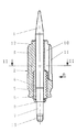
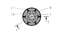
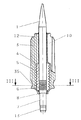
図1〜4において、矢弾形発射体が1で示してあり、そしてこの矢弾形発射体1に設けられた装弾筒が2で示してある。装弾筒2は、繊維強化された耐熱性の熱可塑性合成樹脂からなる装弾筒外周壁3と、軽金属からなる装弾筒本体4を備えている。この装弾筒本体4は装弾筒外周壁3によって完全に取り囲まれている。この場合、装弾筒外周壁3は装弾筒本体4の外周溝5に係合し、矢弾形発射体1の前端部と後端部の一部を含んでいる。矢弾形発射体1は装弾筒本体4にねじ込まれている。この場合、矢弾形発射体1のねじ6の長さは、良好な飛しょう特性を達成するために、短くなっている。ねじ6は装弾筒本体4から突出し、小径の滑らかなシャフト7に移行している。この場合、装弾筒外周壁3によって取り囲まれた肩部8が形成されている。装弾筒外周壁3はその後側端部に、複数の凹部9を備えている。この凹部は予定破断個所、すなわち弱め個所としての働きをする。装弾筒外周壁3の前側部分には、周囲に均一に分配された、後側に向かってテーパー状に先細になっている6つの通路10が設けられている。この通路はほぼプリズム状の横断面を有する。通路10は、同様に後側に向かってテーパー状に先細になっているスリット11を介して装弾筒外周壁3の表面につながっている。それによって、6個のセグメントが形成される。しかし、装弾筒外周壁3は3つ、4つまたは5つの通路10とスリット11を備えていてもよい。12は溝を示している。この溝は図示していないフードを固定するために役立つ。矢弾形発射体1の後端には、他のねじ13が設けられている。このねじによって、同様に図示していない安定化翼が固定可能である。
【0008】
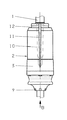
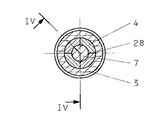
図5,6では、装弾筒本体4が周溝5を備えたセグメントによって形成された複数の部分からなる中空体で形成されている。この中空体の外径は装弾筒外周壁3の直径と比べて小さい。セグメントはいわゆる分離個所28で互いに接触し、その端範囲において内側領域に歯状部を備えている。この歯状部は装弾筒本体を形成する中空体を矢弾形発射体1に固着するために設けられている。装弾筒外周壁3の後側範囲には更に、固定溝35が設けられている。
【0009】
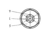
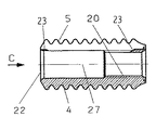
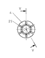
図7〜9では、他の実施の形態に従って、装弾筒本体4が周溝5を備えた中空円筒体からなっている。この中空円筒体の外径は装弾筒外周壁3の直径と比べて小さい。装弾筒本体4は後端に、矢弾形発射体1にねじ止めするためのめねじ20を備えている。装弾筒本体4には、周囲に均一に分配配置された、6個のセグメントを形成する6つのスリット21が設けられている。このスリットは装弾筒本体4の前側端面22から後側端部まで延び、この後側端部において予定破断個所23によって画成されている。見やすくするために図示していない他の変形では、この予定破断個所23が前側端面22およびまたはスリット21の中央領域に形成されている。
【0010】
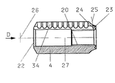
図8に詳細に示すように、例えば予定破断個所23の画成面24が円弧25上にあり、この円弧の曲率中心26は装弾筒本体4の中心軸線27上にある。6つのスリット21の代わりに、装弾筒本体4は3つ、4つまたは5つのスリット21を備えていてもよい。この場合それぞれ同様に、多数のセグメントが形成される。図8,10に示した実施の形態では、装弾筒本体4が90°の角度だけずらして配置した4つのスリット30を備えている。スリット30の範囲には、装弾筒本体4の全長にわたって延びる円弧状の凹部31が設けられている。この場合、凹部の円弧の曲率中心32はスリット30の対称軸線33上にある。凹部31内に溝34が設けられている。この溝は図7の実施の形態の周溝5に一致している。図8には、図10のVI−VI線に沿った溝34の縦断面が示してある。この実施の形態により、重量が大幅に軽くなり、それによって発射後生じる金属破片による危険が一層小さくなる。
【図面の簡単な説明】
【図1】 矢弾形発射体を備えた本発明による装弾筒の、図2のI−I線に沿った縦断面図である。
【図2】 図1のII−II線に沿った装弾筒の横断面図である。
【図3】 図1の矢印A方向から装弾筒を見た図である。
【図4】 図3の矢印B方向から装弾筒を見た図である。
【図5】 矢弾形発射体を備えた本発明による装弾筒の変形例の、図6のIV−IV線に沿った縦断面図である。
【図6】 図5のIII−III線に沿った装弾筒の横断面図である。
【図7】 図9のV−V線に沿った装弾筒本体の拡大縦断面図である。
【図8】 図10のVI−VI線に沿った装弾筒本体の拡大縦断面図である。
【図9】 第1の実施形の装弾筒本体を、図7の矢印C方向から見た図である。
【図10】 第2の実施形の装弾筒本体を、図8の矢印D方向から見た図である。
【符号の説明】
1 矢弾形発射体
2 装弾筒
3 装弾筒外周壁
4 装弾筒本体
5 周溝
6 ねじ
7 シャフト
8 肩部
9 凹部
10 通路
11 スリット
12 溝
13 ねじ
20 めねじ
21 スリット
22 前側端面
23 予定破断個所
24 画成面
25 円弧
26 円弧の曲率中心
27 中心軸線
28 分離面
30 スリット
31 凹部
32 円弧の曲率中心
33 対称軸線
34 周溝
35 固定溝[0001]
BACKGROUND OF THE INVENTION
As described in the superordinate concept of
[0002]
[Prior art]
In the case of such a shell, the shell main body and the shell outer peripheral wall are divided into segments. In this case, the contact surface between the segments of the bullet tube body and the contact surface between the segment of the bullet tube body and the arrow-shaped body cause a leakage problem.
From the European Patent Application No. 0624774, the above-mentioned bullet tube is known. In this case, in order to overcome the above-mentioned leakage problem, the shell body is segmented into a special shape by a longitudinal slit. The longitudinal slit has a T-shaped cross section at least partially. Furthermore, a hermetic seal in the form of a seal cap with a closure seal and a planned break point located within the inner diameter of the shell body are provided. The outer diameter of the shell main body decreases from the rear to the front, that is, the envisaged envelope surface of the shell main body has an essentially conical shape. The circumferential groove of the bullet tube body is not formed as a regularly divided groove, but is formed as individual protrusions or shoulders alternately protruding forward or backward.
[0003]
This shell is relatively complex and therefore very expensive to manufacture. Furthermore, gas may leak from the abutting portion between the outer peripheral wall of the loading cylinder and the loading cylinder main body. Further, when the loading cylinder is dropped during firing, the loading cylinder main body is large, so that relatively large metal fragments are generated.
[0004]
[Problems to be solved by the invention]
The problem underlying the present invention is to provide a loading cylinder of the kind mentioned at the outset, which does not have the aforementioned drawbacks.
[0005]
[Means for Solving the Problems]
This problem is solved by the features described in
[0006]
Advantageous embodiments of the shell are evident from the dependent claims 2-14.
The effect obtained by the present invention is that an optimum seal is achieved by completely embedding the bullet cylinder main body in the bullet barrel outer peripheral wall made of synthetic resin. This is because there is no metal surface and a minute gap is avoided. The main body of the shell is easy to manufacture and is small compared to the state of the art, so the entire shell is light and small light metal fragments are produced after firing. This narrows the dangerous area of the muzzle area. The breakage portion of the shell cylinder body is formed so that separation without failure occurs as much as possible after firing. The ammunition projectile does not have much engagement grooves, resulting in optimal air resistance and slight weight reduction.
[0007]
DETAILED DESCRIPTION OF THE INVENTION
Next, the present invention will be described in detail with reference to the drawings and based on two embodiments.
1 to 4, an ammunition projectile is indicated by 1, and a loaded cylinder provided on the
[0008]
5 and 6, the bullet cylinder
[0009]
In FIGS. 7 to 9, according to another embodiment, the
[0010]
As shown in detail in FIG. 8, for example, the defined
[Brief description of the drawings]
FIG. 1 is a longitudinal sectional view taken along the line II of FIG. 2, of a loading cylinder according to the present invention having an arrow-shaped projectile.
FIG. 2 is a cross-sectional view of the loading cylinder along the line II-II in FIG.
FIG. 3 is a view of a loading cylinder as seen from the direction of arrow A in FIG. 1;
4 is a view of a loading cylinder as viewed from the direction of arrow B in FIG. 3;
FIG. 5 is a longitudinal sectional view taken along line IV-IV in FIG. 6 of a modified example of the loading cylinder according to the present invention provided with an arrow projectile.
6 is a cross-sectional view of the loading cylinder taken along line III-III in FIG. 5;
7 is an enlarged vertical cross-sectional view of a bullet cylinder main body taken along line VV in FIG. 9;
8 is an enlarged vertical cross-sectional view of the shell main body taken along line VI-VI in FIG.
FIG. 9 is a view of the loading cylinder body of the first embodiment as viewed from the direction of arrow C in FIG.
FIG. 10 is a view of a bullet cylinder body according to a second embodiment as viewed from the direction of arrow D in FIG.
[Explanation of symbols]
DESCRIPTION OF
Claims (14)
さらに、装弾筒外周壁(3)を備え、装弾筒外周壁(3)は、装弾筒本体(1)の前側端部を少なくとも部分的に及び装弾筒本体(4)を部分的に取り囲んでおり、
その際、装弾筒本体(4)が、周囲溝(5,34)を備えた一体の又は多部分から成る中空体の形を有し、かつ装弾筒本体(4)の外径が、装弾筒外周壁(3)の肩部(8)の周囲の範囲を除いて、装弾筒外周壁(3)の直径よりも小さく形成されている、
矢弾形発射体の形をした減口径発射体用の装弾筒において、
装弾筒外周壁(3)が、装弾筒本体(4)を完全に取り囲みかつ部分的に矢弾形発射体(1)の後側端部をも取り囲み、
装弾筒本体(4)のすべての周囲溝(5,34)が、同様に形成されており,そして、
隣接する周囲溝が、同様に形成された突出部によって、装弾筒本体(4)の外径が本質的にその全長に亘って一定であるように,分離されている、
ことを特徴とする矢弾形発射体の形の減口径反射体用の装弾筒。It is provided with a shell body (4), and an arrow-shaped projectile (1) is fixed in the shell body,
In addition, a shell outer peripheral wall (3) is provided, and the shell outer peripheral wall (3) at least partially surrounds the front end of the shell main body (1) and partly the shell main body (4). ,
In this case, the bullet cylinder main body (4) has the shape of an integral or multi-part hollow body with a peripheral groove (5, 34), and the outer diameter of the bullet cylinder main body (4) is Except for the area around the shoulder (8) of the outer peripheral wall (3), the outer peripheral wall (3) is formed smaller than the diameter of the outer peripheral wall (3).
In a shell for a reduced-caliber projectile in the shape of an arrow-shaped projectile,
A shell outer wall (3) completely surrounds the shell main body (4) and partially surrounds the rear end of the arrow-shaped projectile (1);
All the circumferential grooves (5, 34) of the shell body (4) are similarly formed, and
Adjacent circumferential grooves are separated by a similarly formed protrusion so that the outer diameter of the shell body (4) is essentially constant over its entire length,
A bullet tube for a reduced-diameter reflector in the form of an ammunition-shaped projectile.
周囲に均一に分配配置され後側に向かってテーパ状に先細になっている或る数の通路(10)が、装弾筒外周壁(3)の前側部分に設けられ、通路がほぼプリズム状の横断面を有し、通路(10)が後側に向かってテーパ状に先細になっているスリット(11)を介して装弾筒外周壁(3)の表面に接続し、それによってセグメントが形成されていることを特徴とする装弾筒。The shell according to claim 1, wherein the shell outer wall (3) is divided into segments.
A certain number of passages (10) that are uniformly distributed around the periphery and taper toward the rear side are provided in the front portion of the outer peripheral wall (3) of the shell, and the passage is substantially prism-like. The passage (10) has a cross section and is connected to the surface of the outer peripheral wall (3) of the shell by way of a slit (11) that tapers toward the rear, thereby forming a segment. A bullet tube characterized by that.
周囲にわたって均一に分配された、セグメントを形成する或る数のスリット(21)が装弾筒本体(4)に設けられ、このスリットが装弾筒本体(4)の前側の端面(22)から後側端部まで延びていることを特徴とする装弾筒。The shell according to claim 1, wherein the shell main body (4) is divided into segments.
A certain number of slits (21) forming a segment, which are uniformly distributed over the circumference, are provided in the shell main body (4), and these slits are rearward from the front end face (22) of the shell main body (4). A bullet tube characterized by extending to the end.
Applications Claiming Priority (2)
| Application Number | Priority Date | Filing Date | Title |
|---|---|---|---|
| CH19970167/97 | 1997-01-27 | ||
| CH16797 | 1997-01-27 |
Publications (2)
| Publication Number | Publication Date |
|---|---|
| JPH10206099A JPH10206099A (en) | 1998-08-07 |
| JP3672425B2 true JP3672425B2 (en) | 2005-07-20 |
Family
ID=4180788
Family Applications (1)
| Application Number | Title | Priority Date | Filing Date |
|---|---|---|---|
| JP32890697A Expired - Fee Related JP3672425B2 (en) | 1997-01-27 | 1997-11-28 | Reduced projectile shell |
Country Status (12)
| Country | Link |
|---|---|
| US (1) | US5902955A (en) |
| EP (1) | EP0855573B1 (en) |
| JP (1) | JP3672425B2 (en) |
| KR (1) | KR100473218B1 (en) |
| CA (1) | CA2215295C (en) |
| CZ (1) | CZ285053B6 (en) |
| DE (1) | DE59702453D1 (en) |
| ES (1) | ES2152607T3 (en) |
| NO (1) | NO307435B1 (en) |
| PL (1) | PL185689B1 (en) |
| SG (1) | SG79946A1 (en) |
| ZA (1) | ZA979139B (en) |
Families Citing this family (8)
| Publication number | Priority date | Publication date | Assignee | Title |
|---|---|---|---|---|
| US6324986B1 (en) | 1998-11-06 | 2001-12-04 | Oerlikon Contraves Ag | Cartridge-case base for a sub-caliber projectile |
| FR2851038B1 (en) * | 2003-02-10 | 2005-03-18 | Giat Ind Sa | SABOT FOR PROJECTILE UNDER SIZE |
| PT1912532E (en) * | 2005-08-08 | 2010-04-14 | Gaba International Ag | Toothbrush comprising inclined and pointed bristles |
| SE529752C2 (en) * | 2006-04-20 | 2007-11-13 | Eurenco Bofors Ab | Powder loads of multi-perforated rod powder for high-speed projectiles and production thereof |
| US7958829B1 (en) | 2006-11-08 | 2011-06-14 | The United States Of America As Represented By The Secretary Of The Army | Sabot |
| US8096292B1 (en) | 2010-03-24 | 2012-01-17 | Cold Steel | Multiple dart blow gun projectile holder |
| DE102010045474A1 (en) * | 2010-09-16 | 2012-03-22 | Rheinmetall Waffe Munition Gmbh | Projectile with disposable sabot |
| US9714819B1 (en) * | 2013-07-15 | 2017-07-25 | The Boeing Company | Stepped sabots for projectiles |
Family Cites Families (8)
| Publication number | Priority date | Publication date | Assignee | Title |
|---|---|---|---|---|
| CH632086A5 (en) * | 1978-08-08 | 1982-09-15 | Oerlikon Buehrle Ag | METHOD FOR PRODUCING A DRIVING MIRROR BULLET AND DRIVING MIRROR BULLET PRODUCED BY THE METHOD. |
| DE3021914A1 (en) * | 1980-06-11 | 1983-09-08 | Deutsch Franz Forsch Inst | SUB-CALIBAR FLOOR WITH DRIVE RING |
| DE3033041C2 (en) * | 1980-09-03 | 1986-04-10 | L'Etat Français représenté par le Délégué Général pour l'Armement, Paris | Metal and plastic sabot |
| SE444984B (en) * | 1982-05-28 | 1986-05-20 | Bofors Ab | DRIVING ORGANIZATION FOR UNDER-CALIBRATED ROTATION STABILIZED PROJECTIL |
| DE4138598A1 (en) * | 1991-11-23 | 1993-05-27 | Hilti Ag | CONTACTING A BATTERY |
| DE4139598A1 (en) * | 1991-11-30 | 1993-06-03 | Weber Adolf Dipl Ing | Full-calibre shell - with overlength penetrator for defence against guided missiles |
| DE59406170D1 (en) * | 1993-05-13 | 1998-07-16 | Contraves Pyrotec Ag | Driving mirror on a wing-stabilized sub-caliber floor |
| EG21731A (en) * | 1993-09-24 | 2002-02-27 | Contraves Pyrotec Ag | Releasable sabot for a subcaliber projectile |
-
1997
- 1997-07-26 DE DE59702453T patent/DE59702453D1/en not_active Expired - Lifetime
- 1997-07-26 ES ES97112896T patent/ES2152607T3/en not_active Expired - Lifetime
- 1997-07-26 EP EP97112896A patent/EP0855573B1/en not_active Expired - Lifetime
- 1997-08-21 NO NO973852A patent/NO307435B1/en not_active IP Right Cessation
- 1997-09-08 CZ CZ972821A patent/CZ285053B6/en not_active IP Right Cessation
- 1997-09-11 CA CA002215295A patent/CA2215295C/en not_active Expired - Lifetime
- 1997-09-17 SG SG9703437A patent/SG79946A1/en unknown
- 1997-10-06 US US08/944,768 patent/US5902955A/en not_active Expired - Lifetime
- 1997-10-09 KR KR1019970051700A patent/KR100473218B1/en not_active Expired - Lifetime
- 1997-10-13 ZA ZA9709139A patent/ZA979139B/en unknown
- 1997-11-27 PL PL97323427A patent/PL185689B1/en unknown
- 1997-11-28 JP JP32890697A patent/JP3672425B2/en not_active Expired - Fee Related
Also Published As
| Publication number | Publication date |
|---|---|
| EP0855573A1 (en) | 1998-07-29 |
| ES2152607T3 (en) | 2001-02-01 |
| CA2215295A1 (en) | 1998-07-27 |
| US5902955A (en) | 1999-05-11 |
| CZ282197A3 (en) | 1999-02-17 |
| NO973852L (en) | 1998-07-28 |
| KR100473218B1 (en) | 2005-07-11 |
| NO307435B1 (en) | 2000-04-03 |
| CZ285053B6 (en) | 1999-05-12 |
| CA2215295C (en) | 2000-08-22 |
| PL185689B1 (en) | 2003-07-31 |
| PL323427A1 (en) | 1998-08-03 |
| DE59702453D1 (en) | 2000-11-16 |
| SG79946A1 (en) | 2001-04-17 |
| EP0855573B1 (en) | 2000-10-11 |
| ZA979139B (en) | 1998-05-11 |
| NO973852D0 (en) | 1997-08-21 |
| JPH10206099A (en) | 1998-08-07 |
| KR19980070004A (en) | 1998-10-26 |
Similar Documents
| Publication | Publication Date | Title |
|---|---|---|
| US4505204A (en) | Drive element for a sub-calibre projectile | |
| US4142467A (en) | Projectile with sabot | |
| JP3672425B2 (en) | Reduced projectile shell | |
| US5187325A (en) | Cylindrical bullet | |
| HU189807B (en) | Bullet shootable by gun | |
| US9797695B2 (en) | Cartridge | |
| US5063855A (en) | Projectile arrangement | |
| KR101460836B1 (en) | Method for production of a projectile as well as a projectile | |
| EP0995966A2 (en) | Ammunition cartridge and its propellant configuration | |
| US4651649A (en) | Sabot for subcaliber projectiles | |
| MXPA04010335A (en) | Projectile sealing arrangement. | |
| CA2130840C (en) | Releasable sabot for a subcaliber projectile | |
| CA2139255C (en) | Projectile with sabot | |
| IT9021932A1 (en) | CARRIER BULLET STABILIZED BY ROTATION, WITH A METAL FORCING CROWN | |
| US4953466A (en) | Propulsion cage for a subcaliber projectile | |
| US5388523A (en) | Releasable sabot for a fin-stabilized subcaliber projectile | |
| US4776280A (en) | Sabot projectile containing a sabot rear portion having reference fracture locations | |
| CA2287021C (en) | Cartridge-case base for a sub-caliber projectile | |
| US5189254A (en) | Sealing band for an arrow-type projectile | |
| JPH0771900A (en) | A drop-off shell for a small caliber shell | |
| IL152972A (en) | Full-caliber projectile | |
| US5033388A (en) | Projectile base for carrier projectiles | |
| US5905228A (en) | Method for the manufacture of a subcaliber projectile manufactured with this method | |
| GB2207985A (en) | Sabot projectile | |
| GB2241307A (en) | Sabot projectile |
Legal Events
| Date | Code | Title | Description |
|---|---|---|---|
| A131 | Notification of reasons for refusal |
Free format text: JAPANESE INTERMEDIATE CODE: A131 Effective date: 20041116 |
|
| A601 | Written request for extension of time |
Free format text: JAPANESE INTERMEDIATE CODE: A601 Effective date: 20050216 |
|
| A521 | Request for written amendment filed |
Free format text: JAPANESE INTERMEDIATE CODE: A523 Effective date: 20050222 |
|
| A602 | Written permission of extension of time |
Free format text: JAPANESE INTERMEDIATE CODE: A602 Effective date: 20050223 |
|
| TRDD | Decision of grant or rejection written | ||
| A01 | Written decision to grant a patent or to grant a registration (utility model) |
Free format text: JAPANESE INTERMEDIATE CODE: A01 Effective date: 20050412 |
|
| A61 | First payment of annual fees (during grant procedure) |
Free format text: JAPANESE INTERMEDIATE CODE: A61 Effective date: 20050419 |
|
| R150 | Certificate of patent or registration of utility model |
Free format text: JAPANESE INTERMEDIATE CODE: R150 |
|
| FPAY | Renewal fee payment (event date is renewal date of database) |
Free format text: PAYMENT UNTIL: 20090428 Year of fee payment: 4 |
|
| FPAY | Renewal fee payment (event date is renewal date of database) |
Free format text: PAYMENT UNTIL: 20100428 Year of fee payment: 5 |
|
| FPAY | Renewal fee payment (event date is renewal date of database) |
Free format text: PAYMENT UNTIL: 20100428 Year of fee payment: 5 |
|
| FPAY | Renewal fee payment (event date is renewal date of database) |
Free format text: PAYMENT UNTIL: 20110428 Year of fee payment: 6 |
|
| FPAY | Renewal fee payment (event date is renewal date of database) |
Free format text: PAYMENT UNTIL: 20120428 Year of fee payment: 7 |
|
| FPAY | Renewal fee payment (event date is renewal date of database) |
Free format text: PAYMENT UNTIL: 20130428 Year of fee payment: 8 |
|
| FPAY | Renewal fee payment (event date is renewal date of database) |
Free format text: PAYMENT UNTIL: 20140428 Year of fee payment: 9 |
|
| R250 | Receipt of annual fees |
Free format text: JAPANESE INTERMEDIATE CODE: R250 |
|
| R250 | Receipt of annual fees |
Free format text: JAPANESE INTERMEDIATE CODE: R250 |
|
| R250 | Receipt of annual fees |
Free format text: JAPANESE INTERMEDIATE CODE: R250 |
|
| LAPS | Cancellation because of no payment of annual fees |