JP3672319B2 - Fabric formed by a paper manufacturer and process for making paper using this fabric - Google Patents
Fabric formed by a paper manufacturer and process for making paper using this fabric Download PDFInfo
- Publication number
- JP3672319B2 JP3672319B2 JP53186197A JP53186197A JP3672319B2 JP 3672319 B2 JP3672319 B2 JP 3672319B2 JP 53186197 A JP53186197 A JP 53186197A JP 53186197 A JP53186197 A JP 53186197A JP 3672319 B2 JP3672319 B2 JP 3672319B2
- Authority
- JP
- Japan
- Prior art keywords
- machine direction
- yarn
- yarns
- fabric
- additional
- Prior art date
- Legal status (The legal status is an assumption and is not a legal conclusion. Google has not performed a legal analysis and makes no representation as to the accuracy of the status listed.)
- Expired - Fee Related
Links
Images


Classifications
-
- D—TEXTILES; PAPER
- D21—PAPER-MAKING; PRODUCTION OF CELLULOSE
- D21F—PAPER-MAKING MACHINES; METHODS OF PRODUCING PAPER THEREON
- D21F1/00—Wet end of machines for making continuous webs of paper
- D21F1/0027—Screen-cloths
- D21F1/0036—Multi-layer screen-cloths
- D21F1/0045—Triple layer fabrics
-
- D—TEXTILES; PAPER
- D21—PAPER-MAKING; PRODUCTION OF CELLULOSE
- D21F—PAPER-MAKING MACHINES; METHODS OF PRODUCING PAPER THEREON
- D21F1/00—Wet end of machines for making continuous webs of paper
- D21F1/0027—Screen-cloths
-
- Y—GENERAL TAGGING OF NEW TECHNOLOGICAL DEVELOPMENTS; GENERAL TAGGING OF CROSS-SECTIONAL TECHNOLOGIES SPANNING OVER SEVERAL SECTIONS OF THE IPC; TECHNICAL SUBJECTS COVERED BY FORMER USPC CROSS-REFERENCE ART COLLECTIONS [XRACs] AND DIGESTS
- Y10—TECHNICAL SUBJECTS COVERED BY FORMER USPC
- Y10S—TECHNICAL SUBJECTS COVERED BY FORMER USPC CROSS-REFERENCE ART COLLECTIONS [XRACs] AND DIGESTS
- Y10S162/00—Paper making and fiber liberation
- Y10S162/903—Paper forming member, e.g. fourdrinier, sheet forming member
Landscapes
- Paper (AREA)
Description
【0001】
関連出願のクロスリファレンス
本明細書は1994年9月16日出願の同時係属出願米国特許出願第08/307937号明細書の一部継続である。
発明の分野
本発明は織物すなわち織られた布、とりわけ紙を形成する布に関する。
【0002】
従来の技術の説明
従来の長網抄紙機による製紙方法では、製紙原料として知られているセルロース繊維の水スラリーすなわち懸濁液が、織りワイヤ及び/又は合成物質の走行エンドレスベルトの上部区間の上面に供給される。ベルトは紙製造表面を提供し、フィルタとして作用し、これによりセルロース繊維が水性媒体から分離され、これにより湿紙ウェブが形成される。湿紙ウェブを形成する際に、形成ベルトはフィルタ要素として用いられ、これにより、水性媒体がセルロース繊維から、排水孔として知られているベルトのメッシュ開口を介して水性媒体を分離し、ベルトすなわち「布」の機械側に配置されている吸引手段等により排水することが可能にされる。形成セクションから出ると紙ウェブは機械のプレスセクションに搬送され、その場所で紙ウェブは、共働するプレスロールにより形成されている一連の圧力ニップを通過し、これにより更に湿気が除去される。次いで紙は、更なる湿気除去のための乾燥セクションに搬送される。
【0003】
このような抄紙用布は、エンドレスベルトを形成するために2つの基本的方法により製造される。これらの布は、平織製法により平織され、これらの布の端部は、複数の良く知られている方法のうちの任意の1つの方法により継合せられ、これによりエンドレスベルトが形成される。代替的にこれらの布は、エンドレス織り製法により連続ベルトの形で直接的に織られる。平織された抄紙用布では、たて糸が機械方向に延在し、よこ糸が機械方向交差方向に延在する。エンドレス方式で織られた抄紙用布では、たて糸が機械方向交差方向に延在し、よこ糸が機械方向に延在する。本明細書において使用される「機械方向」及び「機械方向交差方向」の用語はそれぞれ、製紙機械における抄紙用布の走行方向に等しい方向、及びこの走行方向に対して横断する方向を意味する。双方の方法は当業者に良く知られており、「エンドレスベルト」との用語は本明細書では、いずれかの方法により形成されたベルトを意味する。
【0004】
効果的なシート支持及びワイヤマーキングの欠如は、紙製造において重要な考慮の対象であり、なかんずく、ウェットウェブが形成される抄紙機の形成セクションにとって重要である。ワイヤマーキングの問題は、形成される布のシート側表面の滑らかさがクリティカルである精緻な紙グレードの形成においてとりわけ大切である。マーキングは多数の紙特性例えばシートマーク、多孔性、シースルー、針穴等に影響する。従って、化炭、煙草、電気コンデンサ、高品質印刷及び同様のグレードの精緻な紙に使用される紙グレードはこれまでは、非常に精緻に織られて形成される布か又は精緻なメッシュを形成する布で形成されていた。良好な紙品質を保証するために、製紙原料に接触する抄紙用布の面により、機械方向交差方向で製紙原料のための高い支持を提供しなければならない。何故ならばヘッドボックスから形成布に供給される紙繊維は一般的に、機械方向交差方向よりは機械方向によりアライメントされるからである。排水工程の間に形成布の上面でこれらの紙繊維を捕捉することは、同一平面の表面を有する透水性構造を提供することにより効果的に達成され、この透水性構造により紙繊維は布の支持グリットを橋絡し、支持グリットとアライメントすることはしない。「同一平面」とは、紙形成表面を画定するすべての糸の上部末端が同一のレベルにあり、これによりこのレベルではほぼ「平面的」な表面が形成されることを意味する。
【0005】
しかし、このような形成布はしばしば脆弱であり、機械方向及び機械方向交差方向で安定性が無く、寿命が短い。抄紙機との接触により惹起される浸食性かつ接着性摩耗は大きい問題である。抄紙機に接触する側の抄紙用布の面は頑健で高い持久性を有しなければならない。しかしこのような品質はしばしば、抄紙用布のシート側の面に望まれる良好な排水性及び繊維支持特性と相容れない。
【0006】
双方の基準を満足するために布の2つの層が、これらの層をつなぎ合せるために1インチ当り異なるサイズ及び/又は番手の糸と別の糸とを利用することにより同時に織ることが可能である。この布は二重層布と通常呼ばれる。代替的に布は使用して形成され、これにより、布の紙ウェブに面する表面が望ましい紙製造品質を有し、機械に接触する表面が望ましい耐摩耗性を有することが可能である。例えば抄紙用布を2つの別個の布で形成することが可能であり、一方の布は、紙接触側の面に望まれる品質を有し、他方の布は、機械に接触する側の面に望まれる品質を有し、これらの布を第3の組の糸によりつなぎ合せる。このタイプの布は通常は三層布と呼ばれる。一般的にこれらの構造は、紙製造布に望まれる高い耐伸張性を有しない。更に、布をつなぎ合せる糸はしばしばシートマークを形成する。これはしばしば長い機械方向浮き糸に起因するものである。従って公知の布は、優れた紙を製造するために互いに競合する基準を満足するのに必要な品質を達成していない。
【0007】
Robert G.Wilsonの名前で1991年1月29日に発行された米国特許第4987929号明細書において紙製造機械で使用される改善された抄紙用布が提供され、この布は、紙接触表面に1浮き糸機械方向ナックルを有する最初の布層を含み、この布の中に繊維を支持する付加的な機械方向交差方向糸が織り込まれ、この機械方向交差方向糸は有利には、布層糸に比してより短い直径を有する。繊維を支持する付加的な機械方向交差方向糸は、通常は繊維支持糸とほぼ同一の直径を有する付加的な機械方向交差方向ロケータ糸により、隣接する布層機械方向交差方向糸の間の中心に位置決めされて保持されている。米国特許第4987929号明細書の抄紙用布は単層、二重層又は三層であることもあり、非常に効果的なデザインである。
【0008】
しかし、米国特許第4987929号明細書は、別個のロケータ及び繊維支持付加的機械方向交差方向糸を含む。すなわち付加的な機械方向交差方向糸のうちの1つが繊維支持糸として作用し、この繊維支持糸は、付加的機械方向交差方向糸のうちの他方により、隣接するベース布の機械方向交差方向糸の間の中心に位置決めされている。この構造では繊維支持糸は有利には、繰返しにおいてただ1つのベース布機械方向糸の下に下降する。繊維支持糸がベース布の中に下降する点において繊維支持糸は、1浮き糸ロケータ糸により中心に位置決めされている。
【0009】
従って米国特許第4987929号明細書の布の上面トポグラフィは僅かに均一でない、何故ならば付加的な機械方向交差方向ロケータ糸及び繊維支持糸は、等しい数の隣接するベース布層機械方向糸の上を通過しないからである。この僅かな不均一性は、この布を使用して形成された紙シートにワイヤマーキングを形成する傾向を有する。
更に米国特許第4987929号明細書の織り方では、付加的な機械方向交差方向ロケータ糸のみが、多重布層構造の中にステッチするのに使用される。米国特許第4987929号明細書の布は非常に高い持久性を有するにもかかわらず、布寿命及び内部布摩耗が、ステッチ点の数を増加することにより改善されることが可能であることが分かった。
従って、米国特許第4987929号明細書に示され説明されている布の利点を提供するが、しかし、ステッチ点の数を増加することによりワイヤマーキングを低減し布寿命を改善することにより布を改善する、紙を形成する布の必要性が存在する。
【0010】
発明の要約
従って本発明の目的は、優れた繊維支持表面を有する抄紙用布を提供することであり、この場合、布の、機械に接触する側の面の耐摩耗性が維持される。
本発明の別の目的は、非常に多数の紙繊維支持糸が微細であり、小さい直径を有し、従って高品質の支持が紙製造表面に提供され、湿紙に接触する表面の開放性は、効果的な排水のために高いままである抄紙用布を提供することにある。
本発明の更なる目的は、紙製造表面に圧倒的に多数の機械方向交差方向支持浮き糸を有する抄紙用布を提供することにあり、この場合、機械方向糸ナックルは1浮き糸より大きくない。
本発明の更に別の目的は、優れた安定性及び耐摩耗性を有する抄紙用布を提供することにあり、この場合、布のシート側の面の望ましい紙製造特性は損なわれない。
【0011】
本発明の更に別の目的は、本明細書に説明される抄紙用布を使用して高品質の紙を形成する方法を提供することにある。
前述の目的及びその他の目的に鑑みて、後に説明されるように本発明の1つの特徴は、少なくとも1つの組の機械方向交差方向糸と少なくとも1つの組の機械方向糸とが織り込まれている布層を有する抄紙用布を提供することにあり、これにより紙製造表面と、機械に接触する表面とが形成され、紙製造表面には交互に単一ナックルが形成される。第1の付加的な機械方向交差方向糸は、布層の紙製造表面における機械方向交差方向糸のうちの隣接する機械方向交差方向糸の間に位置決めされている。第2の付加的な機械方向交差方向糸は、布層の紙製造表面における機械方向交差方向糸のうちの隣接する機械方向交差方向糸の間に位置決めされている。第1及び第2の付加的な機械方向交差方向糸のそれぞれは、第1及び第2の付加的な機械方向交差方向糸の他方の機械方向交差方向糸のためのロケータ糸である。第1及び第2の付加的な機械方向交差方向糸は布層に反対の織りパターンで織り込まれている。
【0012】
部品の構造及び組合せの種々の新規の詳細を含む本発明の前述した特徴及びその他の特徴が添付図面を参照してより詳細に説明され、請求の範囲で指摘される。本発明を実施する特定の布は説明のためにのみ示され、本発明の制限として示されているのではない。本発明の原理及び特徴は、本発明の範囲から逸脱することなしに種々の多数の実施の形態で利用されることが可能である。
【0013】
有利な実施の形態の詳細な説明
本発明の布が概略的に説明され、より詳細な説明が後続する。抄紙用布は優れた紙製造表面を提供し、なかんずく紙製造機械の形成セクションに適する。本発明の布の特徴は機械方向交差方向すなわち機械方向を交差する方向に2つの付加的な糸が存在することにある。
【0014】
本発明の布は、特別の織り方を有する抄紙用布である。本発明の理解を容易にするために布はあたかも布層が初めに織られ、次いで付加的な糸が付加されるように説明される。勿論、本発明により製造される抄紙用布は、通常行われるように1つのステップの織り方で織られる。
【0015】
本発明の布の中で利用される糸は、抄紙用の最終的な布の所望の特性に依存して変化する。例えば糸はマルチフィラメント糸、モノフィラメント糸、マルチフィラメントより糸又はモノフィラメントより糸、紡績糸、又はこれらの任意の組合せであることもある。本発明を利用するために所望の布の目的に依存して糸タイプを選択することは、当業者に自明である。
【0016】
本発明の布で使用する糸は、抄紙用布で通常使用されている糸であることもある。これらの糸は綿、羊毛、ポリプロピレン、ポリエステル、アラミド、ナイロン等であることもある。この場合にも当業者は最終的な布の特定の用途にして糸材料を選択することが可能である。本発明の布の縫製での使用に非常に有利であるとして通常使用されている糸は、「Trevira」との商標でHoechst Celanese Fiber Industries社により販売されているポリエステルモノフィラメント糸である。
【0017】
初めに布層構造が形成される。この層は単層布であることも多層布であることもある。しかし布の紙接触表面は1浮き糸すなわち1本の糸に跨る浮き糸の機械方向ナックルを有しなければならない。1浮き糸機械方向ナックルとは、いかなる機械方向糸も、布層の中央又は底部の中に下方へ向かって入込む前に2つ以上の順次の機械方向交差方向糸の上を越えて通過することはないことを意味する。布層の紙接触表面に載置している長い機械方向糸浮き糸の代わりに、ナックルが設けられている。更にベース構造布には、交互に配した一連のナックルが設けられ、これらのナックルは、布層の互いに隣接する2つの機械方向交差方向糸に載置されている。
【0018】
布層構造の紙製造表面に織り交ぜられて2つの組の付加的な機械方向交差方向糸、すなわち第1の付加的な機械方向交差方向糸と第2の付加的な機械方向交差方向糸とが設けられている。いかなる場所でも第1の付加的機械方向交差方向糸と第2の付加的機械方向交差方向糸とのうちのいずれか一方が繊維支持糸として用いられ、これに対して糸交差場所においては双方の糸はロケータ糸(位置決め糸)として用いられる。「繊維支持糸」とは、紙形成工程の間に短い長さの紙スラリー繊維を支持する糸である。「ロケータ糸」とは、布機械方向交差方向糸の間の中間の適所で繊維支持糸を係止する糸を意味する。布の1つの有利な実施の形態では、第1及び第2の付加的機械方向交差方向糸は、ベース構造布を形成する糸に比してより小さい直径を有する。より小さい直径の付加的な第1の機械方向交差方向糸と、ひいては第2の機械方向交差方向糸も、ベース布の紙製造表面の機械方向交差方向糸の寸法及びスペースにより支配される。図7の三層の有利な実施の形態では、ベース布層の機械方向交差方向糸は約0.15mm〜0.20mmであり、付加的な機械方向交差方向糸は0.09mm〜0.17mmである。一般的に、より細い糸の直径は、初めの布層機械方向交差方向糸の直径の約1/2である。ベース布構造のためのその他の適切な糸直径と、相応する第1及び第2の付加的な機械方向交差方向糸とが次の表に示されている。
【0019】

第1及び第2の付加的な糸は、機械方向交差方向の繊維支持糸及びロケータ糸として用いられ、これらの第1及び第2の付加的な糸はおおよそ、初めの布層の紙接触表面の互いに平行な機械方向交差方向糸の間に位置する。2つの付加的な機械方向交差方向糸は、おおよそ逆の織りパターンで初めの(又はベース)布層の紙製造表面の中に織り込まれ、この織り込みは、自然の割込み力によりこれら2つの糸が、2つの隣接する初めの布層機械方向交差方向糸の間の中央にアライメントされるように行われる。割込みする対の糸のうちのそれぞれの糸は付加的な繊維支持糸として機能し、割込みする対の糸のそれぞれの糸は、紙製造表面における適切な又は理想的な位置に繊維支持糸を位置決めするためにロケータ糸として作用する。
【0021】
第1及び第2の付加的な機械方向交差方向糸は、おおよそ互いに対して反対の織りパターンで布層の紙接触表面の中に織り込まれ、これにより終点が形成される。付加的な第1の糸及び付加的な第2の糸の終点は、これらの2つの糸が互いに交差し、位置を相互交換する点として定められる。本発明はこれらの終点が、隣接するベース織り機械方向交差方向糸の間の中央に配置されていることを必要とする。
【0022】
布層の2つの隣接する機械方向交差方向糸における交互に配した機械方向ナックルの列が、付加的な繊維支持糸のためのリフタ点として作用する。更に第1及び第2の付加的な糸のうちの1つの糸は、これらの付加的な糸のうちの他方の糸を、2つの隣接するベース織り機械方向交差方向糸の間の中央に位置決めするように作用する。ロケータ糸に作用する複数の力は互いに等しく、繊維支持糸に作用する力に対して反対の方向である。
【0023】
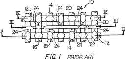
図1〜図4において抄紙用布の従来の構造は繊維単層10を含み、繊維単層10は機械方向交差方向糸12を有し、機械方向交差方向糸12は機械方向糸14に織り交ぜられていることが分かる。糸12,14の交差点は隆起ノブ状部分すなわちナックル16を形成し、ナックル16は平面図(図1)に長円形18により概略的に示されている。それぞれの長円形18の長手軸線は、上方から見て形成される布の最上位置レベルで最下位置糸の上を越える最上位置糸の方向を示す。
【0024】
層10は、繊維を支持する付加的な機械方向交差方向糸20と付加的な機械方向交差方向ロケータ糸22とが設けられている。図1〜図4に示されている布は、前述の米国特許第4987929号明細書に開示され、布の紙製造表面に奇数の長さすなわち奇数本の糸に跨る長さの比較的短い浮き糸(図3)を有する布を提供し、形成された紙に汚点・傷跡等を残す傾向がより小さく、更に、効果的な排水を提供する。
【0025】
付加的な繊維支持糸20は、近隣の機械方向交差方向糸12の間の中間で支持が必要とされる点で機械方向糸14のための支持を付加するために用いられる。繊維支持糸20の直径が小さいことに起因して、機械方向交差方向糸12の間のスペースは、適切な排水のために比較的開いた状態のままである。機械方向糸14は、繊維支持糸20に対して「上り勾配」か又は「下り勾配」で角度を形成しているので、繊維支持糸は、かまわずにおくと「下り勾配」で走行する傾向を有する。すなわち、機械方向交差方向糸が機械方向糸の下方に位置するナックルから、機械方向交差方向糸が前記の機械方向糸の上方に位置する近隣のナックルへ向かって走行する。機械方向糸14における「下り勾配」スロープを意味する図1の矢印24を参照されたい。ロケータ糸無しに繊維支持糸を提供することの結果が、前述の特許第4987929号明細書の図3における12A及び12Bに示されている。これらの図に示されているように繊維支持糸は、近隣の布機械方向交差方向糸へ向かって下り勾配でスライドする傾向を有する。
【0026】
繊維支持糸20が「下り勾配」で移動するのを阻止するためにロケータ糸22は繊維支持糸20と対にされ、機械方向糸12のスロープに抗するように動作し、これにより繊維支持糸20は、機械方向交差方向糸12の間の中間の繊維支持糸20の位置から移動することを惹起するバイアス変位が阻止される。機械方向糸14の山及び谷の自然の力は、大きさが等しく方向が反対の力により2つのより細い糸に作用し、これにより付加的な繊維支持糸20が中心に位置決めされる。このようにしてロケータ糸22は、繊維支持糸20をその適切な位置に係止するために用いられる。
【0027】
本発明の有利な実施の形態が図5〜図7に示されている。ベース布機械方向糸14と機械方向交差方向糸12とは互いに織り込まれ、これにより1浮き糸ナックル16が機械方向と機械方向交差方向との双方に形成される。第1の付加的な機械方向交差方向糸20”は第1の奇数番号の隣接の機械方向布糸14の上を通過し、これに対して第2の付加的な機械方向交差方向糸22”は、第2の奇数番号の隣接の機械方向布糸14の下を通過する。この布糸14は、繰返しの反対の織りパターンの中の糸20”、22”に比して太い。図5〜図7の有利な構造では、隣接した機械方向布糸の第1及び第2の奇数番号(又は浮き長)は、双方共に3である。
【0028】
付加的な機械方向交差方向糸のための浮き長が奇数であり、第1の付加的な機械方向交差方向糸20”と第2の付加的な機械方向交差方向糸22”とは布と織り交ぜられ、これにより浮き糸の両端40は1浮き糸機械方向糸ナックル16により持上げられている。それぞれの付加的な機械方向交差方向20”,22”の双方の浮き端部40も、隣接のベース布機械方向交差方向糸12の間の中心に位置決めされている。この織り方は従来に比して、均一な寸法を持つ改善された排水孔を提供し、改善された機械方向交差方向繊維支持を提供する。
【0029】
図5〜図7において付加的な糸20”及び22”のための1つの有利な織りパターンが示されている。第1の実施の形態の場合と同様に、双方の付加的な糸20”,22”は繊維支持糸として用いられ、双方共にロケータ糸として用いられる。分かり易く比較が容易なように機械方向糸14は図5〜図7において符号1〜10により示され、最上部布層10’の機械方向糸は図9において同様に示されている。図7の第2の布層26は、符号30〜39により示されている機械方向糸14’を含む。
【0030】
図5及び図6に示されているように、第1の付加的な糸20”のそれぞれは、有利には3つの機械方向糸14すなわち1〜3の番号の糸の浮き糸の上を越えて延在し、4〜6の番号の機械方向糸の下を越えて延在し、7〜9の番号の3つの糸の別の浮き糸の上を越えて延在し、以下同様に繰返される。第2の付加的な糸22”は1〜3の番号の機械方向糸の下を越えて延在し、4〜6の番号の3つの糸の上を越えて延在し、7〜9の番号の3つの機械方向糸の下を越えて延在し、3つの糸の上を越えて延在し、以下同様に繰返される。このようにして機械方向糸1〜3、及び7〜9に対して、付加的な第1の糸20”は繊維支持糸として用いられる。同様に機械方向糸4〜6、及び10に対して、付加的な第2の糸22”は繊維支持糸として用いられる。例えば機械方向糸3と4との間、6と7との間、及び9と10との間等の交差点、又は第1及び第2の付加的な機械方向交差方向糸の浮き糸「終点」40において、第1及び第2の付加的な糸は、それぞれ他方の付加的な糸のためのロケータ糸として作用する。
【0031】
三層の実施の形態での1つの有利な織りパターンが示されている図7において、第1の付加的な糸20”は、1〜3の番号の3つの機械方向糸の浮き糸の上を通過し、4〜6の番号の機械方向糸の下を通過し、布層26の機械方向糸34の下を通過する。付加的な糸20”は、布層10’の6及び7の番号の機械方向糸の間の上面の下から現れる。糸20”は上面の下を延在して、布層10’の9及び10の番号の機械方向糸の間のベース布層の中に入込む。
【0032】
第2の付加的な糸22”は、第1の糸20”の織りパターンと反対の織りパターンで同様の経路を辿る。糸22”は、第2の布層26の31の番号の機械方向糸の下を通過し、3と4の番号の機械方向糸の間を通過し、4〜6の番号の3つの糸の浮き糸の上を通過し、7〜9の番号の機械方向糸の下を通過し、更に布層26の中の機械方向糸37の下を通過する。付加的な糸22”は、布層10’の9と10の番号の機械方向糸の間の上面の下から現れる。図7において付加的な糸20”,22”のそれぞれは3つの機能を有する。すなわち(1)繊維支持糸としての機能、(2)ロケータ糸としての機能、及び(3)三層構造の中の第1の布層と第2の布層とのバインダとしての機能である。
【0033】
図8に示されているように、付加的な機械方向交差方向糸20”,22”は、図8の1〜13の番号の5つの隣接の機械方向ベース布糸14の上を越えて浮くように織られることが可能である。三層の5浮き糸すなわち5本の糸に跨る浮き糸の実施の形態における1つの有利な織りパターンが図9により示され、この場合、底部布層26のベース布糸14’が30〜42の番号により示されている。別のより長い奇数の浮き長さも可能であり、これにより、繊維安定性を犠牲にするとともに、付加的な機械方向交差方向糸とベース布の機械方向交差方向糸との局部的な対形成を犠牲にして、繊維支持性が改善される。それにもかかわらず、最上部ベース布層機械方向交差方向糸寸法が0.15〜0.20mmであり、付加的な機械方向糸寸法が0.09〜0.17mmであり、上層端部番手が70〜80epiである三層の実施の形態では、図7の場合のように3の浮き長が好ましい。3つの糸分の浮き長が良好な織り安定性を提供し、紙製造での繊維と付加的な機械方向交差方向糸とのもつれの危険を最小化する。
【0034】
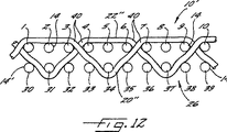
図10〜図12において付加的な機械方向交差方向糸20”,22”も、異なる奇数の浮き長を有する反対の織り方で織られることが可能である。図10及び11において例えば第1の機械方向糸20”は、5本の隣接の機械方向ベース布糸すなわち糸3〜7の浮き糸の上を越えて延在し、次いで糸7と糸8との間の紙製造表面の下に下降する。付加的な機械方向交差方向糸20”はベース布の中で3本の隣接のベース布機械方向糸すなわち糸8〜10の浮き糸の下を更に延在し、次いで戻って糸10と糸11との間の紙製造表面の中に入込む。付加的な機械方向糸22”は、糸20”の織りパターンと反対の織りパターンで織られ、5本の機械方向ベース布糸すなわち糸3〜7の浮き糸の下を延在し、次いで糸7と糸8との間を通過して、3本の機械方向布糸すなわち糸8〜10の浮き糸の上を越えて延在する。このようにして付加的な機械方向交差方向糸のそれぞれは、隣接のベース布機械方向交差方向糸の間の中心に互いを位置決めし、付加的な機械方向交差方向糸のそれぞれは、異なる浮き長にわたる繊維支持糸として作用する。
【0035】
三層の実施の形態における1つの有利な織りパターンが示されている図12において、第1の付加的な糸20”は3〜7の番号の5本の機械方向糸の浮き糸の上を越えて通過し、8〜10の番号の機械方向糸の下を通過し、布層26の中の機械方向糸29の下を通過する。付加的な糸20”は布層10’の機械方向糸10と機械方向糸11との間の上面の下から現れる。
第2の付加的な糸22”は、第1の糸20”の織りパターンと反対の織りパターンを辿る。糸22”は最上部布層10’の糸3〜7の下を通過し、第2の布層26の25の番号の機械方向糸の下を通過し、7と8の番号の機械方向糸の間の通過し、8〜10の番号の3本の糸の浮き糸の上を通過し、次いで糸10と糸11を通過してベース布層の中に入込む。
【0036】
図5〜図12の織りを形成するために、第1及び第2の付加的な機械方向交差方向糸の浮き長が等しい場合には付加的な機械方向交差方向糸浮き長の偶数倍に等しい最小数の通糸が必要であり、双方の浮き長が等しくない場合には第1及び第2の付加的な機械方向交差方向糸の浮き長の和に等しい最小数の通糸が必要である。このようにして例えば図6の実施の形態では最小数6の通糸が必要である。図7の三層の実施の形態では最小数12のハーネスが必要である。最小数8の通糸が図11の布のために必要である。16の通糸が図12の布のために必要である。
【0037】
本発明の三層の実施の形態ではいくつかの底部織り構造が可能である。選択された底部織りに依存して機械側縦縫い回数は変化するか、又はある付加的な機械方向交差方向糸での縫いは不可能である。更に付加的な機械方向交差方向糸浮き糸の順次の対の相対位置は、使用可能な縫い個所により制限される。いずれのあや織底部織りが破断しても付加的な機械方向交差方向糸浮き糸は同一の破断したあや織を辿ることが可能である。これも紙製造プロセスにとって有益である。何故ならば紙に伝達されたワイヤマークもあや織が無いからである。
【0038】
図13において本明細書に説明された抄紙用布を使用する高品質紙を形成する方法がブロック図で示されている。この方法は、本発明の繊維支持糸及びロケータ糸を含む抄紙用布を提供するステップ50と、布の上にスラリーを置く(前述のような)従来の長網抄紙機による製紙方法のステップ51と、種々の段階でスラリーから湿気を除去するステップ52とを含む。従来の紙製造方法で本発明の抄紙用布を使用し、なかんずく、奇数の隣接のベース布機械方向糸の上を浮く付加的な機械方向交差方向糸を有する前述の布を使用することにより、従来の技術に比して滑らかな表面と優れた印刷性とを有する高品質紙が形成される。
【0039】
このようにして、優れた繊維支持表面を有する抄紙用布が提供され、その際、頑丈な耐摩耗性の機械接触側が維持され、非常に多数の紙繊維支持糸が布糸に比して微細な布が提供され、これにより高品質の支持が提供され、しかし排水のために必要な開放性が維持される。更に、紙製造表面における機械方向交差方向支持浮き糸が優勢である布が提供され、その際、いずれの機械方向糸ナックルも1浮き糸より大きくない。
本発明は本明細書に開示している及び/又は図に示されている特定の構造に制限されず、請求の範囲の中のいかなる変更又は等価も含む。
【図面の簡単な説明】
本発明の図示の実施の形態が示されている添付図面が参照され、添付図面から本発明の新規の特徴及び利点が明らかになる。
図1は従来の紙製造布層の一部の部分的に線図で示されている平面図、図2は図1のII−II切断線に沿って切断して示す断面図、図3は図1のIII−III切断線に沿って切断して示す断面図、図4は図1のIV−IV切断線に沿って切断して示す断面図、図5は本発明の1つの有利な実施の形態を示す紙製造布層の1つの形状の一部を部分的に線図で示す平面図、図6は図5のXI−XI切断線に沿って切断して示す断面図、図7は図6に類似であるがしかし本発明の別の代替実施の形態を示す断面図、図8は図6に類似であるがしかし本発明の更に別の実施の形態を示す断面図、図9は本発明の別の代替実施の形態を示す断面図、図10は本発明の更に別の実施の形態を示す紙製造布層の1つの形状の一部を部分的に線図で示す平面図、図11は図10のXVI−XVI切断線に沿って切断して示す断面図、図12は図11に類似であるがしかし本発明の別の代替実施の形態を示す断面図、図13は本明細書に説明されている紙製造業者の布を使用して紙を形成するための方法を示すブロック図である。[0001]
Cross reference of related applications
This specification is a continuation-in-part of co-pending application Ser. No. 08 / 307,937, filed Sep. 16, 1994.
Field of Invention
The present invention relates to woven or woven fabrics, especially fabrics that form paper.
[0002]
Description of conventional technology
In a conventional papermaking method using a long paper machine, an aqueous slurry or suspension of cellulose fibers known as a papermaking raw material is supplied to the upper surface of the upper section of a woven wire and / or a synthetic endless belt. The belt provides a paper manufacturing surface and acts as a filter, whereby cellulose fibers are separated from the aqueous medium, thereby forming a wet paper web. In forming the wet web, the forming belt is used as a filter element, which separates the aqueous medium from the cellulosic fibers through the mesh openings of the belt known as drain holes, and thus the belt or It is possible to drain water by suction means or the like disposed on the machine side of the “cloth”. Upon exiting the forming section, the paper web is conveyed to a press section of the machine where the paper web passes through a series of pressure nips formed by cooperating press rolls, thereby further removing moisture. The paper is then conveyed to a drying section for further moisture removal.
[0003]
Such papermaking fabrics are manufactured by two basic methods to form an endless belt. These fabrics are plain woven by a plain weave process, and the ends of these fabrics are spliced together by any one of a number of well known methods, thereby forming an endless belt. Alternatively, these fabrics are woven directly in the form of a continuous belt by an endless weaving process. In a plain woven papermaking fabric, warp yarns extend in the machine direction and weft yarns extend in the cross direction of the machine direction. In a papermaking fabric woven in an endless manner, warp yarns extend in the cross direction of the machine direction and weft yarns extend in the machine direction. As used herein, the terms “machine direction” and “cross direction of machine direction” mean a direction equal to the traveling direction of the papermaking cloth in the papermaking machine and a direction transverse to the traveling direction, respectively. Both methods are well known to those skilled in the art, and the term “endless belt” herein refers to a belt formed by either method.
[0004]
The lack of effective sheet support and wire marking,It is an important consideration in paper manufacturing and, inter alia, is important for the forming section of a paper machine where a wet web is formed. The problem of wire marking is especially in the formation of fine paper grades where the smoothness of the sheet side surface of the fabric being formed is critical.BigIt is off. Marking affects a number of paper properties such as sheet marks, porosity, see-through, needle holes, and the like. Therefore, paper grades used for charcoal, cigarettes, electrical capacitors, high quality printing and similar grades of fine paper have so far formed very finely woven fabrics or fine meshes. Was made of cloth. The surface of the papermaking fabric in contact with the papermaking raw material to ensure good paper qualityBy,MachineMust provide high support for papermaking raw materials in the cross direction.This is because the paper fibers fed from the headbox to the forming fabric are generally aligned in the machine direction rather than in the machine direction cross direction. Top surface of the fabric formed during the drainage processsoCapturing these paper fibers is effectively accomplished by providing a water permeable structure with a coplanar surface that allows the paper fibers to bridge the supporting grit of the fabric.ShiDo not align with support grit. “Coplanar” means that the upper ends of all yarns that define the paper-forming surface are at the same level, thereby forming a substantially “planar” surface at this level.
[0005]
However,Such formed fabrics are often fragile, have no stability in the machine direction and cross direction, and have a short life. Erosive and adhesive wear caused by contact with a paper machine is a major problem. The side of the paper fabric that contacts the paper machine must be robust and highly durable. However, such qualities are often incompatible with the good drainage and fiber support properties desired on the sheet-side surface of papermaking fabrics.
[0006]
BothBaseTo satisfy the criteria, two layers of fabric are woven simultaneously by utilizing different sizes and / or count yarns per inch and another yarn to join these layers togetherRuIt is possible. This fabric is commonly referred to as a double layer fabric. Alternatively, the fabric is formed using, so that the surface of the fabric facing the paper web has the desired paper manufacturing quality, and the surface in contact with the machine can have the desired abrasion resistance. For example, papermaking clothTheTwo separate fabricssoOne fabric has the desired quality on the side that contacts the paper, and the other fabric has the desired quality on the side that contacts the machine.TheTying together with a third set of threadsRu. This type of fabric is usually called a three-layer fabric. In general, these structures are the high desired for papermaking fabrics.NoNot stretch resistant. In addition, yarns that join fabrics often form sheet marks.To do.This is often a long machine direction floatyarncaused byIs a thing. Known fabrics therefore compete with each other to produce excellent paperBaseThe quality required to satisfy the standards is not achieved.
[0007]
Robert G. In U.S. Pat. No. 4,987,929, issued Jan. 29, 1991 under the name of Wilson, an improved papermaking fabric for use in a paper making machine is provided, which floats on a paper contact surface.yarnIncluding an initial fabric layer having a machine direction knuckle and interwoven with additional machine direction cross direction yarns that support the fibers, the machine direction cross direction yarns are advantageously compared to the fabric layer yarns. Have a shorter diameter. The additional machine direction cross direction yarns that support the fiber are centered between adjacent fabric layer machine direction cross direction yarns, typically by an additional machine direction cross direction locator yarn having approximately the same diameter as the fiber support yarn. Is positioned and held. The papermaking fabric of U.S. Pat. No. 4,987,929 may be single layer, double layer or triple layer and is a very effective design.
[0008]
However,U.S. Pat. No. 4,987,929 includes separate locators and fiber-supported additional machine direction cross direction yarns.MuThat is, one of the additional machine direction cross direction yarns acts as a fiber support yarn, which is supported by the other of the additional machine direction cross direction yarns by the other of the machine direction cross direction yarns of the adjacent base fabric. Is centered between. In this construction, the fiber support yarn advantageously descends under a single base fabric machine direction yarn in repetition. The fiber support yarn floats one point at the point where the fiber support yarn descends into the base fabric.yarnCentered by the locator thread.
[0009]
Thus, the top surface topography of the fabric of US Pat. No. 4,987,929 is not slightly uniform because additional machine direction cross locator yarns and fiber support yarns can be used over an equal number of adjacent base fabric layer machine direction yarns. Because it does not pass through. This slight non-uniformity tends to form wire markings on the paper sheet formed using this fabric.
Furthermore, in the weaving of US Pat. No. 4,987,929, only additional cross machine direction locator yarns are used to stitch into the multiple fabric layer structure. Although the fabric of U.S. Pat. No. 4,987,929 has very high durability, it has been found that fabric life and internal fabric wear can be improved by increasing the number of stitch points. It was.
Accordingly, it provides the advantages of the fabric shown and described in US Pat. No. 4,987,929, but improves the fabric by increasing the number of stitch points to reduce wire marking and improve fabric life. There is a need for a cloth forming paper.
[0010]
Summary of invention
Accordingly, it is an object of the present invention to provide a papermaking fabric having an excellent fiber support surface, in which case the wear resistance of the surface of the fabric that contacts the machine is maintained.
Another object of the present invention is that a very large number of paper fiber support yarns are fine and have a small diameter so that high quality support is provided on the paper production surface and the openness of the surface in contact with the wet paper is It is to provide a papermaking cloth that remains high for effective drainage.
It is a further object of the present invention to have an overwhelming number of machine direction cross support floats on the paper manufacturing surface.yarnIn that case, the machine direction yarn knuckle is 1 floatyarnNot bigger.
Yet another object of the present invention is to provide a papermaking fabric having excellent stability and abrasion resistance, in which case the desired paper manufacturing properties of the fabric sheet side are not compromised.
[0011]
It is yet another object of the present invention to provide a method of forming high quality paper using the papermaking fabric described herein.
The abovePurpose andOther purposesInIn view of this, as will be described later, one feature of the present invention is a papermaking fabric having a fabric layer in which at least one set of machine direction cross direction yarns and at least one set of machine direction yarns are woven. In this manner, a paper manufacturing surface and a machine contacting surface are formed, and a single knuckle is alternately formed on the paper manufacturing surface. The first additional machine direction cross direction yarns are positioned between adjacent machine direction cross direction yarns of the machine direction cross direction yarns on the papermaking surface of the fabric layer. A second additional machine direction cross direction yarn is positioned between adjacent machine direction cross direction yarns of the machine direction cross direction yarns on the papermaking surface of the fabric layer. Each of the first and second additional machine direction cross direction yarns is a locator yarn for the other machine direction cross direction yarn of the first and second additional machine direction cross direction yarns. The first and second additional machine direction cross direction yarns are woven into the fabric layer in opposite weave patterns.
[0012]
The foregoing of the present invention including various novel details of the structure and combination of partsFeaturesAnd other features are described in more detail with reference to the accompanying drawings and pointed out in the claims. The particular fabric embodying the invention is shown by way of illustration only and not as a limitation of the invention. The principles and features of the present invention may be utilized in a number of different embodiments without departing from the scope of the present invention.
[0013]
Detailed Description of the Preferred Embodiments
The fabric of the present invention is schematically described, followed by a more detailed description. Papermaking fabrics provide an excellent papermaking surface and are especially suitable for the forming section of papermaking machines. The fabric of the present invention is characterized in that there are two additional yarns in the cross machine direction, i.e. in the direction crossing the machine direction.
[0014]
The fabric of the present invention is a papermaking fabric having a special weaving method. The present inventionofFor ease of understanding, the fabric is described as if the fabric layer was first woven and then additional yarns were added. Of course, the papermaking fabric produced in accordance with the present invention is woven in a one-step weave as is usually done.
[0015]
The yarns utilized in the fabrics of the present invention will vary depending on the desired properties of the final papermaking fabric. For example, the yarn may be a multifilament yarn, a monofilament yarn, a multifilament yarn or a monofilament strand, a spun yarn, or any combination thereof. The present inventionTheChoosing a thread type depending on the purpose of the desired fabric to use,To those skilled in the artSelfIt is clear.
[0016]
With the cloth of the present inventionMessengerforDoThe yarn may be a yarn that is normally used in papermaking fabrics. These yarns may be cotton, wool, polypropylene, polyester, aramid, nylon and the like. Again, those skilled in the art can select the yarn material for the particular application of the final fabric. Very advantageous for use in sewing the fabric of the present inventionAsA commonly used yarn is a polyester monofilament yarn sold by Hoechst Celanese Fiber Industries under the trademark "Trevira".
[0017]
First, a fabric layer structure is formed. This layer may be a single layer fabric or a multilayer fabric. But the paper contact surface of the fabric is one floatyarnIn other words, floating over one threadyarnMachine direction knuckle. 1 floatyarnWhat is a machine direction knuckle?,Any machine direction thread should go down into the middle or bottom of the fabric layer.TheMeans that it does not pass over two or more sequential cross machine direction yarns before entering. Long machine direction thread float resting on the paper contact surface of the fabric layeryarnInstead of a knuckle. Furthermore, the base structure cloth,Alternately arrangedA series ofKnuckles are provided, and these knuckles are mounted on two mutually crossing machine direction yarns of the fabric layer.
[0018]
Two sets of additional machine direction cross direction yarns interwoven with fabric layered paper manufacturing surface,A first additional machine direction cross direction yarn and a second additional machine direction cross direction yarn;Is providedThe Any one of the first additional machine direction cross direction yarns and the second additional machine direction cross direction yarnsEither oneAre used as fiber support yarns, whereas both yarns are used as locator yarns (positioning yarns) at the yarn intersection. A “fiber support yarn” is a yarn that supports a short length of paper slurry fiber during the paper forming process. “Locator yarn” means a yarn that locks a fiber support yarn in place in the middle between cloth machine direction cross direction yarns. In one advantageous embodiment of the fabric, the first and second additional machine direction cross direction yarns have a smaller diameter than the yarns forming the base structure fabric. An additional first machine direction cross direction yarn of smaller diameter, and thus a second machine direction cross direction yarn, is also governed by the size and space of the machine direction cross direction yarn of the base fabric papermaking surface. Figure7In an advantageous embodiment of the three layers, the machine direction cross direction yarns of the base fabric layer are about 0.15 mm to 0.20 mm and the additional machine direction cross direction yarns are 0.09 mm to 0.17 mm. . In general, the diameter of the thinner thread is,The first fabric layer is about ½ the diameter of the machine direction cross direction yarn. Other suitable yarn diameters for the base fabric structure and corresponding first and second additional machine direction cross direction yarns are shown in the following table.
[0019]
The first and second additional yarns are used as fiber support yarns and locator yarns in the cross machine direction, and these first and second additional yarns are approximately the paper contacting surface of the initial fabric layer. Between the mutually parallel machine direction cross direction yarns. Two additional machine direction cross-direction yarns are woven into the paper manufacturing surface of the initial (or base) fabric layer in an approximately reverse weaving pattern, which is due to the natural interrupting force that these two yarns This is done so that it is aligned in the middle between two adjacent initial fabric layers in the machine direction cross direction yarn. Each of the interrupting pair of yarns functions as an additional fiber support yarn, and each of the interrupting pair of yarns positions the fiber support yarn in an appropriate or ideal position on the paper manufacturing surface. To act as a locator thread.
[0021]
The first and second additional machine direction cross direction yarns are woven into the paper contacting surface of the fabric layer in a weave pattern that is approximately opposite to each other, thereby forming an end point. The end points of the additional first yarn and the additional second yarn are defined as the points where these two yarns intersect each other and interchange positions. The present invention requires that these end points be centered between adjacent base weaving machine direction cross direction yarns.
[0022]
Alternate rows of machine direction knuckles in two adjacent machine direction cross direction yarns of the fabric layer serve as lifter points for additional fiber support yarns. Further, one of the first and second additional yarns positions the other of these additional yarns in the middle between two adjacent base weaving machine direction cross direction yarns. Acts like The forces acting on the locator yarn are equal to each other and in opposite directions to the forces acting on the fiber support yarn.
[0023]
1-4, the conventional structure of a papermaking fabric includes a
[0024]
[0025]
Additional
[0026]
The
[0027]
BookInventionYesA good embodiment is illustrated5~ Figure7Is shown inBeThe machine direction
[0028]
The float length for the additional machine direction cross direction yarn is odd,FirstOne additional machine direction
[0029]
Figure5~ Figure7One advantageous weave pattern for
[0030]
Figure5And figure6As shown, each of the first
[0031]
Figure showing one advantageous weave pattern in a three-layer embodiment7The first
[0032]
The second
[0033]
Figure8As shown, the additional machine direction
[0034]
FIG.0~ Figure 12The additional machine direction
[0035]
FIG. 1 illustrates one advantageous weave pattern in a three-layer embodiment.2The first
The second
[0036]
Figure5~ Figure 12If the first and second additional machine direction cross-direction yarn float lengths are equal, the machine direction cross-direction yarn float length is equal to an even multiple of the additional machine direction cross-direction yarn float length.A minimum number of threads is requiredIf the float lengths are not equal, a minimum number of threads is required which is equal to the sum of the float lengths of the first and second additional cross machine direction yarns. In this way, for example,6In this embodiment, a minimum number of 6 threads is required. Figure7The three-layer embodiment requires a minimum number of 12 harnesses. The minimum number of 8 threads is shown in Fig. 1.1Is needed for the cloth. 16 threading is shown in Fig. 1.2Is needed for the cloth.
[0037]
Several bottom woven structures are possible in the three-layer embodiment of the present invention. Depending on the selected bottom weaveMachine sideVertical stitchingTimesMay change, or sewing with some additional cross machine direction threads is not possible. Further machine direction cross direction thread floatyarnThe relative positions of the sequential pairs are limited by the available sewing points. If any twill bottom weave breaks, additional machine direction cross direction yarn floatyarnCan follow the same broken twill. This is also beneficial for the paper manufacturing process.This is because the wire mark transmitted to the paper has no twill.
[0038]
FIG.3A method for forming high quality paper using the papermaking fabric described herein is shown in block diagram form. This method comprises step 50 of providing a papermaking fabric comprising the fiber support yarns and locator yarns of the present invention and step 51 of a conventional papermaking method with a conventional long paper machine (as described above) placing a slurry on the fabric. And step 52 of removing moisture from the slurry at various stages. By using the papermaking fabric of the present invention in a conventional paper manufacturing method, inter alia, using the aforementioned fabric with additional machine direction cross direction yarns floating above an odd number of adjacent base fabric machine direction yarns, High-quality paper having a smooth surface and excellent printability compared to conventional techniques is formed.
[0039]
In this way, a papermaking fabric having an excellent fiber support surface is provided, in which a sturdy, wear-resistant machine contact side is maintained and a very large number of paper fiber support yarns are finer than the fabric yarns. Fabric is provided, which provides high quality support but maintains the openness necessary for drainage. In addition, the machine direction cross support float on the paper manufacturing surfaceyarnIs provided, with one machine direction yarn knuckle floatingyarnNot bigger.
The present invention is not limited to the specific structures disclosed herein and / or shown in the figures, but includes any modifications or equivalents in the claims.
[Brief description of the drawings]
The novel features and advantages of the present invention will become apparent from the following detailed description, taken in conjunction with the accompanying drawings, in which illustrated embodiments of the invention are shown.
FIG. 1 is a plan view of a part of a conventional paper manufacturing fabric layer partially shown in a diagram, FIG. 2 is a sectional view taken along the line II-II in FIG. 1, and FIG. 1 is a cross-sectional view taken along the line III-III in FIG. 1, and FIG. 4 is a cross-sectional view taken along the line IV-IV in FIG.,Figure5Figure 2 is a plan view, partly diagrammatically showing part of one shape of a paper-fabric fabric layer, illustrating one advantageous embodiment of the invention;6Is a figure5Sectional drawing which cuts and shows along the XI-XI cutting line of FIG.7Is a figure6A cross-sectional view similar to that but showing another alternative embodiment of the present invention, FIG.8Is a figure6, But is a cross-sectional view showing yet another embodiment of the present invention.9IsBookFIG. 1 is a cross-sectional view illustrating another alternative embodiment of the invention.0FIG. 1 is a plan view partially showing in diagram form a part of one shape of a paper manufacturing fabric layer showing still another embodiment of the present invention;1Figure 10FIG. 1 is a sectional view taken along line XVI-XVI of FIG.2Figure 11FIG. 1 is a cross-sectional view similar to FIG. 1 but showing another alternative embodiment of the present invention.3FIG. 4 is a block diagram illustrating a method for forming paper using a paper manufacturer's fabric as described herein.
Claims (16)
ベース布層を具備し、該ベース布層は機械方向交差方向布糸と機械方向布糸とを含み、前記機械方向交差方向布糸と前記機械方向布糸とは前記ベース布層の中に織り込まれ、これにより紙製造表面が形成され、該紙製造表面には、機械方向と機械方向交差方向とで交互に単一ナックルが形成され、
第1の付加的な機械方向交差方向糸を具備し、該第1の付加的な機械方向交差方向系は、前記紙製造表面における前記機械方向交差方向布糸のうちの隣接する前記機械方向交差方向布糸の間に位置決めされ、前記第1の付加的な機械方向交差方向糸は前記ナックルの一部を形成せず、
第2の付加的な機械方向交差方向糸を具備し、該第2の付加的な機械方向交差方向糸は、前記紙製造表面における前記機械方向交差方向布糸のうちの隣接する前記機械方向交差方向布糸の間に位置決めされ、前記第2の付加的な機械方向糸は前記ナックルの一部を形成せず、
前記第1及び第2の付加的な機械方向交差方向糸は、前記ベース布層に反対の織り方で織り込まれ、前記第1の付加的な機械方向交差方向糸は、第1の奇数の第1の隣接する機械方向布糸の上を越えて通過し、第2の奇数の次の隣接する機械方向布糸の下を通過し、前記第2の付加的な機械方向交差方向糸は前記第1の奇数の前記第1の隣接する機械方向布糸の下を通過し、前記第2の奇数の前記次の隣接する機械方向布糸の上を越えて通過し、前記第1および第2の奇数が3以上の数であり、
前記第1及び第2の付加的な機械方向交差方向糸のそれぞれは繊維支持糸として用いられ、前記第1及び第2の付加的な機械方向交差方向糸のそれぞれは、前記第1及び第2の付加的な機械方向交差方向糸のうちの他方の前記付加的な機械方向交差方向糸を、前記機械方向交差方向布糸のうちの前記隣接する前記機械方向布糸の間のほぼ中心位置に位置決めするためのロケータ糸として用いられることを特徴とする抄紙用布。A papermaking cloth,
A base fabric layer, the base fabric layer including a machine direction cross direction fabric yarn and a machine direction fabric yarn, wherein the machine direction cross direction fabric yarn and the machine direction fabric yarn are woven into the base fabric layer; This forms a paper manufacturing surface, on which a single knuckle is formed alternately in the machine direction and the cross direction of the machine direction,
A first additional machine direction cross direction yarn, wherein the first additional machine direction cross direction system is adjacent to the machine direction cross direction of the machine direction cross direction fabric yarns on the paper manufacturing surface. Positioned between the direction fabric yarns, the first additional machine direction cross direction yarn does not form part of the knuckle;
A second additional machine direction cross direction yarn, wherein the second additional machine direction cross direction yarn is adjacent to one of the machine direction cross direction fabric yarns on the paper manufacturing surface. Positioned between the direction fabric yarns, the second additional machine direction yarn does not form part of the knuckle;
The first and second additional machine direction cross direction yarns are woven into the base fabric layer in opposite weaves, and the first additional machine direction cross direction yarns are a first odd number of second direction yarns. Passing over one adjacent machine direction fabric yarn, passing under a second odd next adjacent machine direction fabric yarn, said second additional machine direction cross direction yarn being said first Pass under the first odd number of the first adjacent machine direction fabric yarns, pass over the second odd number of the next adjacent machine direction fabric yarns, and the first and second The odd number is a number of 3 or more,
Each of the first and second additional machine direction cross direction yarns is used as a fiber support yarn, and each of the first and second additional machine direction cross direction yarns is the first and second The other machine direction cross direction yarn of the other machine direction cross direction yarns at a substantially central position between the adjacent machine direction cloth yarns of the machine direction cross direction yarns. A papermaking fabric characterized by being used as a locator yarn for positioning.
抄紙用布を提供するステップを有し、
前記形成される布は、
ベース布層を有し、該ベース布層は機械方向交差方向布糸と機械方向布糸とを含み、前記機械方向交差方向布糸と前記機械方向布糸とは前記ベース布層の中に織り込まれ、これにより紙製造表面が形成され、該紙製造表面には、機械方向と機械方向交差方向とで交互に単一ナックルが形成され、
第1の付加的な機械方向交差方向糸を有し、該第1の付加的な機械方向交差方向糸は、前記紙製造表面における前記機械方向交差方向布糸のうちの隣接する前記機械方向交差方向布糸の間に位置決めされ、前記第1の付加的な機械方向交差方向糸は前記ナックルの一部を形成せず、
第2の付加的な機械方向交差方向糸を有し、該第2の付加的な機械方向交差方向糸は、前記紙製造表面における前記機械方向交差方向布糸のうちの隣接する前記機械方向交差方向布糸の間に位置決めされ、前記第2の付加的な機械方向交差方向糸は前記ナックルの一部を形成せず、
前記第1及び第2の付加的な機械方向交差方向糸は、前記ベース布層に反対の織り方で織り込まれ、前記第1の付加的な機械方向交差方向糸は、第1の奇数の第1の隣接する機械方向布糸の上を越えて通過し、第2の奇数の次の隣接する機械方向布糸の下を通過し、前記第2の付加的な機械方向交差方向糸は前記第1の奇数の前記第1の隣接する機械方向布糸の下を通過し、前記第2の奇数の前記次の隣接する機械方向布糸の上を越えて通過し、前記第1および第2の奇数が3以上の数であり、
前記第1及び第2の付加的な機械方向交差方向糸のそれぞれは繊維支持糸として用いられ、前記第1及び第2の付加的な機械方向交差方向糸のそれぞれは、前記前記第1及び第2の付加的な機械方向交差方向糸のうちの他方の前記付加的な機械方向交差方向糸を、前記機械方向交差方向布糸のうちの前記隣接する機械方向交差方向布糸の間のほぼ中心位置に位置決めするためのロケータ糸として用いられ、
製紙原料を前記抄紙用布に載置し、これにより湿紙ウェブが形成されるステップと、
該湿紙ウェブから湿気を除去するステップとを有することを特徴とする紙を製造する方法。A method for forming paper, comprising:
Providing a papermaking cloth,
The formed fabric is
A base fabric layer, the base fabric layer including a machine direction cross direction fabric yarn and a machine direction fabric yarn, wherein the machine direction cross direction fabric yarn and the machine direction fabric yarn are woven into the base fabric layer; This forms a paper manufacturing surface, on which a single knuckle is formed alternately in the machine direction and the cross direction of the machine direction,
A first additional machine direction cross direction yarn, wherein the first additional machine direction cross direction yarn is adjacent to one of the machine direction cross direction fabric yarns on the paper manufacturing surface. Positioned between the direction fabric yarns, the first additional machine direction cross direction yarn does not form part of the knuckle;
Having a second additional machine direction cross direction yarn, said second additional machine direction cross direction yarn being adjacent to said machine direction cross direction yarn of said machine direction cross direction fabric yarn on said paper manufacturing surface. Positioned between the direction fabric yarns, the second additional machine direction cross direction yarn does not form part of the knuckle;
The first and second additional machine direction cross direction yarns are woven into the base fabric layer in opposite weaves, and the first additional machine direction cross direction yarns are a first odd number of second direction yarns. Passing over one adjacent machine direction fabric yarn, passing under a second odd next adjacent machine direction fabric yarn, said second additional machine direction cross direction yarn being said first Pass under the first odd number of the first adjacent machine direction fabric yarns, pass over the second odd number of the next adjacent machine direction fabric yarns, and the first and second The odd number is a number of 3 or more,
Each of the first and second additional machine direction cross direction yarns is used as a fiber support yarn, and each of the first and second additional machine direction cross direction yarns is the first and second The other additional machine direction cross direction yarn of the two additional machine direction cross direction yarns is approximately centered between the adjacent machine direction cross direction fabric yarns of the machine direction cross direction fabric yarns. Used as a locator thread for positioning
Placing the papermaking raw material on the papermaking cloth, thereby forming a wet paper web;
Removing the moisture from the wet paper web.
Applications Claiming Priority (3)
| Application Number | Priority Date | Filing Date | Title |
|---|---|---|---|
| US08/611,203 | 1996-03-05 | ||
| US08/611,203 US5709250A (en) | 1994-09-16 | 1996-03-05 | Papermakers' forming fabric having additional fiber support yarns |
| PCT/US1997/003260 WO1997033037A1 (en) | 1996-03-05 | 1997-03-03 | Papermakers' forming fabric and process for producing paper using the same |
Publications (2)
| Publication Number | Publication Date |
|---|---|
| JP2000505512A JP2000505512A (en) | 2000-05-09 |
| JP3672319B2 true JP3672319B2 (en) | 2005-07-20 |
Family
ID=24448042
Family Applications (1)
| Application Number | Title | Priority Date | Filing Date |
|---|---|---|---|
| JP53186197A Expired - Fee Related JP3672319B2 (en) | 1996-03-05 | 1997-03-03 | Fabric formed by a paper manufacturer and process for making paper using this fabric |
Country Status (5)
| Country | Link |
|---|---|
| US (2) | US5709250A (en) |
| JP (1) | JP3672319B2 (en) |
| AU (1) | AU1983997A (en) |
| BR (1) | BR9708175A (en) |
| WO (1) | WO1997033037A1 (en) |
Families Citing this family (47)
| Publication number | Priority date | Publication date | Assignee | Title |
|---|---|---|---|---|
| US5518042A (en) * | 1994-09-16 | 1996-05-21 | Huyck Licensco, Inc. | Papermaker's forming fabric with additional cross machine direction locator and fiber supporting yarns |
| US5983953A (en) * | 1994-09-16 | 1999-11-16 | Weavexx Corporation | Paper forming progess |
| US5709250A (en) * | 1994-09-16 | 1998-01-20 | Weavexx Corporation | Papermakers' forming fabric having additional fiber support yarns |
| US5937914A (en) * | 1997-02-20 | 1999-08-17 | Weavexx Corporation | Papermaker's fabric with auxiliary yarns |
| US5967195A (en) * | 1997-08-01 | 1999-10-19 | Weavexx Corporation | Multi-layer forming fabric with stitching yarn pairs integrated into papermaking surface |
| GB9811089D0 (en) | 1998-05-23 | 1998-07-22 | Jwi Ltd | Warp-tied composite forming fabric |
| US6112774A (en) * | 1998-06-02 | 2000-09-05 | Weavexx Corporation | Double layer papermaker's forming fabric with reduced twinning. |
| PT1002892E (en) | 1998-11-18 | 2002-06-28 | Heimbach Gmbh Thomas Josef | TEXTILE PRODUCT FOR SURFACE COATING |
| GB2351505A (en) | 1999-06-29 | 2001-01-03 | Jwi Ltd | Two-layer woven fabric for papermaking machines |
| US6123116A (en) * | 1999-10-21 | 2000-09-26 | Weavexx Corporation | Low caliper mechanically stable multi-layer papermaker's fabrics with paired machine side cross machine direction yarns |
| US6179013B1 (en) | 1999-10-21 | 2001-01-30 | Weavexx Corporation | Low caliper multi-layer forming fabrics with machine side cross machine direction yarns having a flattened cross section |
| US6334467B1 (en) | 1999-12-08 | 2002-01-01 | Astenjohnson, Inc. | Forming fabric |
| US6585006B1 (en) | 2000-02-10 | 2003-07-01 | Weavexx Corporation | Papermaker's forming fabric with companion yarns |
| GB0005344D0 (en) * | 2000-03-06 | 2000-04-26 | Stone Richard | Forming fabric with machine side layer weft binder yarns |
| US6244306B1 (en) | 2000-05-26 | 2001-06-12 | Weavexx Corporation | Papermaker's forming fabric |
| US6253796B1 (en) | 2000-07-28 | 2001-07-03 | Weavexx Corporation | Papermaker's forming fabric |
| US6379506B1 (en) | 2000-10-05 | 2002-04-30 | Weavexx Corporation | Auto-joinable triple layer papermaker's forming fabric |
| US6745797B2 (en) | 2001-06-21 | 2004-06-08 | Weavexx Corporation | Papermaker's forming fabric |
| US7108019B2 (en) * | 2002-05-24 | 2006-09-19 | Nippon Filcon Co. | Industrial two-layer fabric |
| US6860969B2 (en) | 2003-01-30 | 2005-03-01 | Weavexx Corporation | Papermaker's forming fabric |
| US6837277B2 (en) | 2003-01-30 | 2005-01-04 | Weavexx Corporation | Papermaker's forming fabric |
| US20060231154A1 (en) * | 2003-03-03 | 2006-10-19 | Hay Stewart L | Composite forming fabric |
| US7059357B2 (en) | 2003-03-19 | 2006-06-13 | Weavexx Corporation | Warp-stitched multilayer papermaker's fabrics |
| US6896009B2 (en) * | 2003-03-19 | 2005-05-24 | Weavexx Corporation | Machine direction yarn stitched triple layer papermaker's forming fabrics |
| US6905574B2 (en) * | 2003-04-18 | 2005-06-14 | Albany International Corp. | Multi-layer forming fabric with two warp systems bound together with a triplet of binder yarns |
| FI20030983A (en) * | 2003-06-30 | 2004-12-31 | Tamfelt Oyj Abp | A paper machine fabric |
| GB0317248D0 (en) * | 2003-07-24 | 2003-08-27 | Voith Fabrics Gmbh & Co Kg | Fabric |
| US7243687B2 (en) * | 2004-06-07 | 2007-07-17 | Weavexx Corporation | Papermaker's forming fabric with twice as many bottom MD yarns as top MD yarns |
| JP4440085B2 (en) * | 2004-11-26 | 2010-03-24 | 日本フイルコン株式会社 | Industrial two-layer fabric |
| US7195040B2 (en) * | 2005-02-18 | 2007-03-27 | Weavexx Corporation | Papermaker's forming fabric with machine direction stitching yarns that form machine side knuckles |
| NO338649B1 (en) * | 2005-05-19 | 2016-09-26 | Nippon Filcon Kk | Two-layer industrial structure |
| JP4563260B2 (en) * | 2005-06-14 | 2010-10-13 | 日本フイルコン株式会社 | Industrial two-layer fabric |
| US7484538B2 (en) * | 2005-09-22 | 2009-02-03 | Weavexx Corporation | Papermaker's triple layer forming fabric with non-uniform top CMD floats |
| US7219701B2 (en) * | 2005-09-27 | 2007-05-22 | Weavexx Corporation | Papermaker's forming fabric with machine direction stitching yarns that form machine side knuckles |
| US7275566B2 (en) * | 2006-02-27 | 2007-10-02 | Weavexx Corporation | Warped stitched papermaker's forming fabric with fewer effective top MD yarns than bottom MD yarns |
| US7580229B2 (en) | 2006-04-27 | 2009-08-25 | Hitachi Global Storage Technologies Netherlands B.V. | Current-perpendicular-to-the-plane (CPP) magnetoresistive sensor with antiparallel-free layer structure and low current-induced noise |
| US7487805B2 (en) * | 2007-01-31 | 2009-02-10 | Weavexx Corporation | Papermaker's forming fabric with cross-direction yarn stitching and ratio of top machined direction yarns to bottom machine direction yarns of less than 1 |
| US7624766B2 (en) * | 2007-03-16 | 2009-12-01 | Weavexx Corporation | Warped stitched papermaker's forming fabric |
| JP5466945B2 (en) * | 2007-10-05 | 2014-04-09 | 日本フイルコン株式会社 | Industrial two-layer fabric |
| US20090183795A1 (en) * | 2008-01-23 | 2009-07-23 | Kevin John Ward | Multi-Layer Papermaker's Forming Fabric With Long Machine Side MD Floats |
| US7766053B2 (en) * | 2008-10-31 | 2010-08-03 | Weavexx Corporation | Multi-layer papermaker's forming fabric with alternating paired and single top CMD yarns |
| US7717141B1 (en) | 2009-02-06 | 2010-05-18 | Voith Patent Gmbh | Forming fabric with dual combination binder weft yarns |
| CA2680924A1 (en) * | 2009-09-29 | 2011-03-29 | Richard Stone | Papermakers' forming fabric including pairs of machine side complementary yarns |
| US8251103B2 (en) * | 2009-11-04 | 2012-08-28 | Weavexx Corporation | Papermaker's forming fabric with engineered drainage channels |
| KR102415170B1 (en) | 2013-11-14 | 2022-06-30 | 쥐피씨피 아이피 홀딩스 엘엘씨 | Soft, absorbent sheets having high absorbency and high caliper, and methods of making soft, absorbent sheets |
| US10255572B2 (en) * | 2015-07-09 | 2019-04-09 | Honeywell Asca Inc. | Integration of clothing performance in planning optimization of paper and board machine to reduce manufacturing costs |
| CN110709547A (en) * | 2017-05-30 | 2020-01-17 | 艾斯登强生股份有限公司 | Stack warp dry fabric with long floating warps and high stability |
Family Cites Families (72)
| Publication number | Priority date | Publication date | Assignee | Title |
|---|---|---|---|---|
| DE454092C (en) * | 1927-12-29 | H G Waldhelm Filztuchfabrik | Woven dewatering felt for paper machines | |
| US4093512A (en) * | 1975-04-23 | 1978-06-06 | Huyck Corporation | Papermakers belts having ultra-high modulus load bearing yarns |
| US4529013A (en) * | 1975-10-30 | 1985-07-16 | Scapa-Porritt Limited | Papermakers fabrics |
| US4289173A (en) * | 1975-10-30 | 1981-09-15 | Scapa-Porritt Limited | Papermakers fabrics |
| GB1572905A (en) * | 1976-08-10 | 1980-08-06 | Scapa Porritt Ltd | Papermakers fabrics |
| DE2736796C3 (en) * | 1977-08-16 | 1981-08-27 | Hermann Wangner Gmbh & Co Kg, 7410 Reutlingen | Papermaker's screen and process for its manufacture |
| SE420852B (en) * | 1978-06-12 | 1981-11-02 | Nordiskafilt Ab | The forming fabric |
| USRE33195E (en) * | 1978-08-04 | 1990-04-10 | Asten Group, Inc. | Fabrics for papermaking machines |
| US4244543A (en) * | 1979-01-08 | 1981-01-13 | Exxon Research & Engineering Co. | Support roller or rocker for hot expanding pipe lines |
| US4453573A (en) * | 1980-02-11 | 1984-06-12 | Huyck Corporation | Papermakers forming fabric |
| DE3036409C2 (en) * | 1980-09-26 | 1983-01-20 | Hermann Wangner Gmbh & Co Kg, 7410 Reutlingen | Double-layer screen for the screen part of a paper machine |
| SE430425C (en) * | 1981-06-23 | 1986-09-19 | Nordiskafilt Ab | PREPARATION WIRES FOR PAPER, CELLULOSA OR SIMILAR MACHINES |
| US4633596A (en) * | 1981-09-01 | 1987-01-06 | Albany International Corp. | Paper machine clothing |
| DE3146385C2 (en) * | 1981-11-23 | 1985-10-31 | Hermann Wangner Gmbh & Co Kg, 7410 Reutlingen | Double-layer fabric as a covering for paper machines |
| SE441016B (en) * | 1982-04-26 | 1985-09-02 | Nordiskafilt Ab | PREPARATION WIRES FOR PAPER, CELLULOSA OR SIMILAR MACHINES |
| DE3301810C2 (en) * | 1983-01-20 | 1986-01-09 | Hermann Wangner Gmbh & Co Kg, 7410 Reutlingen | Composite fabric as a covering for the sheet forming part of a paper machine |
| SE435739B (en) * | 1983-02-23 | 1984-10-15 | Nordiskafilt Ab | DOUBLE TEXTILE TYPE FORMATION WIRES |
| DE3307144A1 (en) * | 1983-03-01 | 1984-09-13 | Hermann Wangner Gmbh & Co Kg, 7410 Reutlingen | PAPER MACHINE COVERING IN A FABRIC BINDING THAT DOES NOT HAVE A SYMMETRY AXIS LONGITUDE |
| DE3329740C2 (en) * | 1983-08-17 | 1986-07-03 | Hermann Wangner Gmbh & Co Kg, 7410 Reutlingen | Two- or multi-layer fabric as a covering for the sheet forming part of a paper machine |
| FI844125L (en) * | 1984-03-26 | 1985-09-27 | Huyck Corp | PAPPERSMASKINTYG SOM BESTAOR AV SLITSTARKA TRAODAR. |
| ATE43376T1 (en) * | 1984-06-14 | 1989-06-15 | Oberdorfer Fa F | PAPER MACHINE SCREEN. |
| US4731281A (en) * | 1984-10-29 | 1988-03-15 | Huyck Corporation | Papermakers fabric with encapsulated monofilament yarns |
| DE3445367C1 (en) * | 1984-12-12 | 1986-08-14 | F. Oberdorfer, 7920 Heidenheim | Composite fabric as a paper machine screen |
| US4642261A (en) * | 1984-12-21 | 1987-02-10 | Unaform Inc. | Papermakers fabric having a tight bottom weft geometry |
| US4636426A (en) * | 1985-01-04 | 1987-01-13 | Huyck Corporation | Papermaker's fabric with yarns having multiple parallel monofilament strands |
| FR2597123B1 (en) * | 1986-04-10 | 1988-12-02 | Thuasne & Cie | ELASTIC CONTAINER FABRIC |
| DE3615304A1 (en) * | 1986-05-06 | 1987-11-12 | Wangner Gmbh Co Kg Hermann | COVER FOR THE SHEET FORMING PART OF A PAPER MACHINE |
| EP0224276B1 (en) * | 1986-05-06 | 1990-03-28 | Hermann Wangner GmbH & Co. KG | Screen cloth for the wet end of a paper-making machine |
| US4709732A (en) * | 1986-05-13 | 1987-12-01 | Huyck Corporation | Fourteen harness dual layer weave |
| US4676278A (en) * | 1986-10-10 | 1987-06-30 | Albany International Corp. | Forming fabric |
| DE3635000A1 (en) * | 1986-10-14 | 1988-04-21 | Oberdorfer Fa F | DOUBLE-LAYER PAPER MACHINE SCREEN WITH COARSE-TEXTURED RUNNING SIDE AND FINE-STRUCTURED PAPER SIDE |
| DE3635632A1 (en) * | 1986-10-20 | 1988-04-21 | Wangner Gmbh Co Kg Hermann | COVER FOR THE SHEET FORMING PART OF A PAPER MACHINE |
| US4759975A (en) * | 1986-11-06 | 1988-07-26 | Asten Group, Inc. | Papermaker's wet press felt having multi-layered base fabric |
| CA1277209C (en) * | 1986-11-28 | 1990-12-04 | Dale B. Johnson | Composite forming fabric |
| FI78329B (en) * | 1987-02-10 | 1989-03-31 | Tamfelt Oy Ab | PAPPERSMASKINDUK. |
| DE3705345A1 (en) * | 1987-02-19 | 1988-09-01 | Oberdorfer Fa F | COMPOSITE FABRIC AS A COVER FOR THE SHEET FORMING PART OF A PAPER MACHINE |
| GB8706552D0 (en) * | 1987-03-19 | 1987-04-23 | Scapa Porrtitt Ltd | Papermachine &c clothing |
| SE460125B (en) * | 1987-03-24 | 1989-09-11 | Nordiskafilt Ab | MULTIPLE STORED DRAINAGE BAND FOR PAPER SHEET STRENGTH |
| DE3713510A1 (en) * | 1987-04-22 | 1988-11-10 | Oberdorfer Fa F | PAPER MACHINE SCREEN FROM A DOUBLE-LAYER FABRIC |
| DE3801051A1 (en) * | 1988-01-15 | 1989-07-27 | Wangner Gmbh Co Kg Hermann | DOUBLE-DAY LOADING FOR THE SHEETING AREA OF A PAPER MACHINE |
| US4989647A (en) * | 1988-04-08 | 1991-02-05 | Huyck Corporaiton | Dual warp forming fabric with a diagonal knuckle pattern |
| CA1320410C (en) * | 1988-06-27 | 1993-07-20 | Takuo Tate | Papermakers' double layer type fabrics |
| JP2558155B2 (en) * | 1988-08-31 | 1996-11-27 | 日本フイルコン株式会社 | Single woven fabric for papermaking with horizontal surface of auxiliary weft on the papermaking surface |
| US4909284A (en) * | 1988-09-23 | 1990-03-20 | Albany International Corp. | Double layered papermaker's fabric |
| DE3909534A1 (en) * | 1989-03-22 | 1990-09-27 | Oberdorfer Fa F | FORMING SCREEN FOR THE WET SECTION OF A PAPER MACHINE |
| JP2799729B2 (en) * | 1989-04-18 | 1998-09-21 | 日本フイルコン株式会社 | Endless fabrics and endless papermaking fabrics |
| US4967805A (en) * | 1989-05-23 | 1990-11-06 | B.I. Industries, Inc. | Multi-ply forming fabric providing varying widths of machine direction drainage channels |
| US4942077A (en) * | 1989-05-23 | 1990-07-17 | Kimberly-Clark Corporation | Tissue webs having a regular pattern of densified areas |
| DE3923938A1 (en) * | 1989-07-19 | 1991-01-31 | Oberdorfer Fa F | FORMING FABRICS FOR THE WET SECTION OF A PAPER MACHINE |
| US4987929A (en) * | 1989-08-25 | 1991-01-29 | Huyck Corporation | Forming fabric with interposing cross machine direction yarns |
| DE3938159A1 (en) * | 1989-11-16 | 1991-05-23 | Oberdorfer Fa F | COMPOSITE FABRICS FOR PAPER MACHINE BENCH |
| AT393521B (en) * | 1990-05-08 | 1991-11-11 | Hutter & Schrantz Ag | PLASTIC MONOFILAMENT FABRICS FOR USE AS A DRAINAGE SCREEN OF A PAPER MACHINE |
| FI85605C (en) * | 1990-06-15 | 1994-06-28 | Tamfelt Oy Ab | Tvaoskiktad pappersmaskinsduk |
| US5244543A (en) * | 1990-10-03 | 1993-09-14 | Asten Group, Inc. | Belt filter press fabric |
| US5116478A (en) * | 1990-11-05 | 1992-05-26 | Nippon Filcon Co., Ltd. | Extendable and heat shrinkable polyester mono-filament for endless fabric |
| US5101866A (en) * | 1991-01-15 | 1992-04-07 | Niagara Lockport Industries Inc. | Double layer papermakers fabric having extra support yarns |
| SE469432B (en) * | 1991-11-22 | 1993-07-05 | Nordiskafilt Ab | WOVEN CLOTHING FOR PAPER MACHINES AND LIKE |
| US5219004A (en) * | 1992-02-06 | 1993-06-15 | Lindsay Wire, Inc. | Multi-ply papermaking fabric with binder warps |
| US5228482A (en) * | 1992-07-06 | 1993-07-20 | Wangner Systems Corporation | Papermaking fabric with diagonally arranged pockets |
| JP3076703B2 (en) * | 1993-09-06 | 2000-08-14 | 日本フイルコン株式会社 | Warp single weft double woven fabric for papermaking |
| US5421374A (en) * | 1993-10-08 | 1995-06-06 | Asten Group, Inc. | Two-ply forming fabric with three or more times as many CMD yarns in the top ply than in the bottom ply |
| JP3444373B2 (en) * | 1994-03-18 | 2003-09-08 | 日本フイルコン株式会社 | Warp double weft double papermaking fabric with auxiliary wefts arranged on the papermaking side fabric |
| US5454405A (en) * | 1994-06-02 | 1995-10-03 | Albany International Corp. | Triple layer papermaking fabric including top and bottom weft yarns interwoven with a warp yarn system |
| US5709250A (en) * | 1994-09-16 | 1998-01-20 | Weavexx Corporation | Papermakers' forming fabric having additional fiber support yarns |
| US5518042A (en) * | 1994-09-16 | 1996-05-21 | Huyck Licensco, Inc. | Papermaker's forming fabric with additional cross machine direction locator and fiber supporting yarns |
| JP3517008B2 (en) * | 1994-12-02 | 2004-04-05 | 日本フイルコン株式会社 | Single woven fabric for papermaking |
| US5482567A (en) * | 1994-12-06 | 1996-01-09 | Huyck Licensco, Inc. | Multilayer forming fabric |
| US5520225A (en) * | 1995-01-23 | 1996-05-28 | Wangner Systems Corp. | Pocket arrangement in the support surface of a woven papermaking fabric |
| US5746257A (en) * | 1995-07-06 | 1998-05-05 | Asten, Inc. | Corrugator belt seam |
| JP3510013B2 (en) * | 1995-07-25 | 2004-03-22 | 日本フイルコン株式会社 | Warp single weft triple structure papermaking fabric |
| US5641001A (en) * | 1995-08-16 | 1997-06-24 | Huyck Licensco, Inc. | Papermaker's fabric with additional cross machine direction yarns positioned in saddles |
| JP3474039B2 (en) * | 1995-09-22 | 2003-12-08 | 日本フイルコン株式会社 | Double layer fabric for papermaking |
-
1996
- 1996-03-05 US US08/611,203 patent/US5709250A/en not_active Expired - Fee Related
-
1997
- 1997-03-03 WO PCT/US1997/003260 patent/WO1997033037A1/en active Application Filing
- 1997-03-03 BR BR9708175-2A patent/BR9708175A/en not_active Application Discontinuation
- 1997-03-03 JP JP53186197A patent/JP3672319B2/en not_active Expired - Fee Related
- 1997-03-03 AU AU19839/97A patent/AU1983997A/en not_active Abandoned
- 1997-10-27 US US08/958,025 patent/US5894867A/en not_active Expired - Fee Related
Also Published As
| Publication number | Publication date |
|---|---|
| US5894867A (en) | 1999-04-20 |
| US5709250A (en) | 1998-01-20 |
| AU1983997A (en) | 1997-09-22 |
| JP2000505512A (en) | 2000-05-09 |
| WO1997033037A1 (en) | 1997-09-12 |
| BR9708175A (en) | 2000-01-04 |
Similar Documents
| Publication | Publication Date | Title |
|---|---|---|
| JP3672319B2 (en) | Fabric formed by a paper manufacturer and process for making paper using this fabric | |
| JP2969193B2 (en) | Papermaking fabric | |
| US4989647A (en) | Dual warp forming fabric with a diagonal knuckle pattern | |
| KR100508540B1 (en) | Multi-layer forming fabric with stitching yarn pairs integrated into papermaking surface | |
| JP2896805B2 (en) | Forming fabric with intervening cross-machine directional yarn | |
| USRE40066E1 (en) | Multi-layer forming fabric with stitching yarn pairs integrated into papermaking surface | |
| CA2229613C (en) | Papermaker's fabric with additional cross machine direction yarns positioned in saddles | |
| KR101097745B1 (en) | Multilayer papermaker's fabric having pocket areas defined by a plane difference between at least two top layer weft yarns | |
| CA2429305C (en) | Industrial two-layer fabric | |
| JP3942397B2 (en) | Web forming fabric for three-layer paper machines that can be automatically sewn | |
| US5983953A (en) | Paper forming progess | |
| KR100865773B1 (en) | Papermaker's triple layer forming fabric with non-uniform top CMD floats | |
| KR100732001B1 (en) | Papermaker's forming fabric with machine direction stitching yarns that form machine side knuckles | |
| US7604025B2 (en) | Forming fabric having offset binding warps | |
| JP2006512507A (en) | Double crossed parallel binder cloth | |
| US20060075737A1 (en) | Multi-layer fabric with Bi-nodal MD yarn | |
| CA2248313C (en) | Papermakers' forming fabric and process for producing paper using the same | |
| AU699702B2 (en) | Papermakers' forming fabric |
Legal Events
| Date | Code | Title | Description |
|---|---|---|---|
| A911 | Transfer of reconsideration by examiner before appeal (zenchi) |
Free format text: JAPANESE INTERMEDIATE CODE: A911 Effective date: 20041209 |
|
| TRDD | Decision of grant or rejection written | ||
| A01 | Written decision to grant a patent or to grant a registration (utility model) |
Free format text: JAPANESE INTERMEDIATE CODE: A01 Effective date: 20050401 |
|
| A61 | First payment of annual fees (during grant procedure) |
Free format text: JAPANESE INTERMEDIATE CODE: A61 Effective date: 20050419 |
|
| R150 | Certificate of patent or registration of utility model |
Free format text: JAPANESE INTERMEDIATE CODE: R150 |
|
| LAPS | Cancellation because of no payment of annual fees |