JP3672191B2 - Balloon catheter manufacturing method - Google Patents
Balloon catheter manufacturing method Download PDFInfo
- Publication number
- JP3672191B2 JP3672191B2 JP2001327390A JP2001327390A JP3672191B2 JP 3672191 B2 JP3672191 B2 JP 3672191B2 JP 2001327390 A JP2001327390 A JP 2001327390A JP 2001327390 A JP2001327390 A JP 2001327390A JP 3672191 B2 JP3672191 B2 JP 3672191B2
- Authority
- JP
- Japan
- Prior art keywords
- tube
- balloon
- catheter
- release agent
- manufacturing
- Prior art date
- Legal status (The legal status is an assumption and is not a legal conclusion. Google has not performed a legal analysis and makes no representation as to the accuracy of the status listed.)
- Expired - Fee Related
Links
Images


Classifications
-
- A—HUMAN NECESSITIES
- A61—MEDICAL OR VETERINARY SCIENCE; HYGIENE
- A61M—DEVICES FOR INTRODUCING MEDIA INTO, OR ONTO, THE BODY; DEVICES FOR TRANSDUCING BODY MEDIA OR FOR TAKING MEDIA FROM THE BODY; DEVICES FOR PRODUCING OR ENDING SLEEP OR STUPOR
- A61M25/00—Catheters; Hollow probes
- A61M25/10—Balloon catheters
- A61M25/1027—Making of balloon catheters
- A61M25/1029—Production methods of the balloon members, e.g. blow-moulding, extruding, deposition or by wrapping a plurality of layers of balloon material around a mandril
-
- A—HUMAN NECESSITIES
- A61—MEDICAL OR VETERINARY SCIENCE; HYGIENE
- A61M—DEVICES FOR INTRODUCING MEDIA INTO, OR ONTO, THE BODY; DEVICES FOR TRANSDUCING BODY MEDIA OR FOR TAKING MEDIA FROM THE BODY; DEVICES FOR PRODUCING OR ENDING SLEEP OR STUPOR
- A61M25/00—Catheters; Hollow probes
- A61M25/10—Balloon catheters
- A61M25/1027—Making of balloon catheters
- A61M25/1036—Making parts for balloon catheter systems, e.g. shafts or distal ends
Description
【0001】
【発明の属する技術分野】
本発明はシリコンバルーンカテーテルの製造方法に関するもので、より詳細には、望みのカテーテルの外径より少し小さな外径を有するチューブを1次押出した後、バルーンが形成される部位に離型剤を塗布し、第1チューブの上に2次押出して加硫処理して薄い被膜状の第2チューブを成形することによって、膨脹管に液体を注入すると第1チューブから第2チューブが剥離して膨脹しながらバルーンとしての機能を行うように構成したバルーンカテーテルの製造方法に関するものである。
【0002】
【従来の技術】
通常、シリコンで製造されるカテーテルは人体内に挿入されて体液を抜出したり薬液の注入などを行う細くて長い注排管として、例えば、導尿管に使われて尿道を経て膀胱に進入させて膀胱に集まっている尿を排出させるために使用する。
【0003】
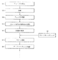
図1は従来のバルーンカテーテルの構成を示す断面図であり、図2は従来技術によるバルーンカテーテルの製造方法を示すフローチャートである。
【0004】
まず、図1に示すように、従来のカテーテルの構成は、尿排出口17を通じて膀胱から流入した尿を排出させる吸引管12およびバルーンを膨脹させるための膨脹管14との間に隔壁19が形成されているチューブ13からなり、このチューブ13の外部には接着剤18によりバルーン層16が形成されている。また、チューブ13の一部分には膨脹管14とバルーンの内部16aとを連通するためのバルーン注入口15が形成されている。
【0005】
このような構成のカテーテルを製造するために図2を参照して説明する。まず吸引管12と膨脹管14を提供するようにチューブ13を押出する(S1)。次に、加硫して(S2)所定の長さに切断する(S3)。
【0006】
続いて、バルーン注入口15と尿排出口17を穿孔し(S4)、尖端部11を成形する(S5)。その後、別の工程でモールディングした(S6)バルーン16を接着剤で接着させた(S7)後、オーバーコーティング処理する(S8)。
【0007】
しかし、前述した従来のバルーンカテーテルは別の工程でモールディングしたバルーンを接着して(S8)製造するので、他の部分に比べてバルーン部位の直径が相対的に太くなって手術時に患者に大きい痛みを与えるようになり、場合によってはバルーンの接着部位が剥離される恐れがある。
【0008】
また、他の従来のカテーテル製造方法がアメリカの特許5,137,671号に開示されている。
【0009】
図3を参照してその製造方法を説明すれば、まず図3aに示したようなチューブ100が供給される。このチューブ100は第1管120(直径が大きい管)と第2管140(直径が小さい毛細管)とからなっている。
【0010】
このようなチューブ100が供給されると、図3bに示すようにチューブの中間部分、すなわちバルーン膨脹部分になる外面から第2管140と通じる第1孔160を穿孔する。次に、チューブ100の一端(下端)から第1孔160に至るまでの第2管140内にシリコンゴムのような重合性充填材180を充填して、チューブ100の下端にはチップ200を固着してチューブの第1管及び第2管120、140の一端を閉鎖させる。
【0011】
次に、チューブ100の一端からバルーン膨脹部まで離型剤溶液(石鹸水あるいはワセリン液等)をA-A線までディッピング及び固形化しながら、チューブ外面のバルーン膨脹部まで離型剤300をコーティングする。これと共に、同じ位置の第1孔160及び第2管140の一部にも離型剤300を充填すれば、図3cのような断面を有するようになる。すなわちバルーン膨脹部のA-A線から第1孔までの第2管内には離型剤が充填され、A-A線とB-B線との間のチューブ外面には離型剤がコーティングされる。
【0012】
その後、図3dに示すように再びチューブ100をバルーン膨脹部の以前(B-B)線まで界面活性剤の処理後、水にディッピングしたり高温の液体に数回浸してバルーン膨脹部以外にコーティングした離型剤を除去し、図3eのようにチューブ100の外面全体に多重層410、420をコーティングしてオーバーコーティング層400を形成する。
【0013】
次に、チューブの第2管140からバルーン膨脹部の充填及びコーティングされた離型剤を除去して、図3fのようにバルーン膨脹のための空間部440を形成する。
【0014】
しかし、このような工程でバルーンカテーテルを製造すれば、チューブを離型剤溶液にディッピングした後、バルーン膨脹部以外の部分(B-B線と一端との間)にコーティングした離型剤を除去する時、水等で数回ディッピングする過程で廃水の発生が増えて環境の汚染を誘発するようになる。
【0015】
また、完全な離型剤の除去が行われない場合に、空間部の形成後バルーン膨脹部が膨脹する時、押される現象が発生して周囲のオーバーコーティング層が剥離されて共に膨らむ問題が発生する。
【0016】
さらに、バルーン部位の直径が他の部分より太いという問題は解決できなかった。
【0017】
もう一つの従来の例としては1995年6月21日に登録された日本特許第3015310号に開示されているシリコンゴムカテーテルがある。
【0018】
これはバルーンがカテーテル本体の表面を被覆するように一体に設けられたもので、シリコンゴムを材料として押出により成形した吸引管と管壁の外に管注槽を有するカテーテルの本体に油化(加硫)処理を行い、その挿設部の離型端(バルーンの成形部)に離型剤を塗布し、その後カテーテル本体の管壁外部に嚢壁(バルーン)を積層し、さらに油化処理して尖端部を形成して、嚢壁とカテーテルの管壁を同一平面の管壁で形成し、管壁面の段差による抵抗を解消すると共に、漏気時に気嚢の壁面に生じる変形を防ぐためのものである。
【0019】
しかし、前記特許で主張するバルーンの膨脹/収縮用の連続的な溝型膨脹管は実際に製造がほとんど不可能である。なぜなら、2次の押出時に被覆されるシリコンゴム層がこの管注槽(溝)を陥没させるためである。万一、陥没させない程度で被覆される場合には1次チューブとの接着力が充分でないので、バルーン部以外の所まで剥離される現象が発生する。
【0020】
【発明が解決しようとする課題】
このような問題点を解決するために本発明は、バルーン部位の段差をなくして手術時に患者に加えられる痛みを緩和させ、バルーン部以外の所が剥離されることを防止すると共に、生産性を高めて製造コストを低減できるシリコンバルーンカテーテル及びその製造方法を提供することを目的としている。
【0021】
【課題を解決するための手段】
前述の目的を達成するために、シリコンバルーンカテーテルの製造方法は、シリコンゴムを利用したバルーンカテーテルの製造方法において、望みのカテーテルの外径より少し小さな外径を有し、内部に吸引管及び膨張管を有するチューブを1次押出して第1チューブを成形した後、加硫処理して切断する段階と、前記第1チューブにおけるバルーンに膨脹される部位の吸引管内に支持棒を挿入した後、2次押出時に第2チューブのシリコンゴムを陥没被覆させない大きさのバルーン注入口を穿孔する段階と、前記バルーン注入口部位に離型剤を塗布する段階と、離型剤が塗布された第1チューブから支持棒を除去した後、連結器を使用して連結し、その塗布された外部に2次押出して第2チューブを成形し、加硫処理して再び切断する段階と、前記第1チューブおよび前記第2チューブの先端に尖端部を成形する段階と、前記尖端部と前記バルーンに膨張される部位との間の前記第1チューブ及び前記第2チューブに前記吸引管に貫通する注排口を穿孔する段階と、を含むことを特徴とする。
【0022】
【発明の実施の形態】
以下、図面を参照しながら本発明の好ましい実施の形態について説明する。
【0023】
バルーン部位の段差がないシリコンゴム材のカテーテルを経済的に生産するために、本発明の好ましい実施の形態では、膨脹管に空気を注入すると、離型剤が塗布された部位で第1チューブと第2チューブとの間が離れることによって膨脹されてバルーンとしての役割をするようになる。これを図4aないし図6を参照して詳しく説明する。
【0024】
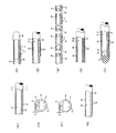
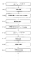
図4aないし図4iは本発明によりバルーンカテーテルの製造する工程を順々に示す縦断面図、図5は本発明によって製造されたバルーンカテーテルの構成を示す断面図、および図6は本発明に係るバルーンカテーテルの製造方法を示すブロック図である。
【0025】
まず、図4aに示すように、本発明の好ましい実施の形態ではバルーンカテーテルの望みの直径より少し小さな外径を有するチューブを1次に押出成形して吸引管22と膨脹管24を提供する第1チューブ20を作る(図6のS11)。次に、加硫処理して弾性を与えながら所定の長さに切断する(S12)。
【0026】
この時、前記第1チューブ20の断面は図4cに示したような形状を持つようになる。図4bは比較のために、従来のチューブの断面形状を示す図面である。
【0027】
これらの図に示すように、従来のチューブ13の断面と本発明の第1チューブ20の断面形状はその形態がほぼ似ているが、本発明の第1チューブ20の厚さtb、Tbが従来のチューブ13の厚さta、Taに比べて非常に薄い。これは次に説明するバルーン注入口の穿孔時に作業の容易性を確保して成功率を高めると共に、排尿吸引管をできるだけ大きく確保するためである。
【0028】
また、第1チューブ20の外部は2次押出時に再び被覆される厚さを鑑みて、図4cに示すように薄く形成される。通常、従来のチューブ13の外周面と膨脹管14との間の厚さtaは0.5mmで、円周の厚さTaは0.9mmであるのに対し、本発明の第1チューブ20の外周面と膨脹管24との間の厚さtbは0.3mmで、第1チューブ20の円周の厚さTbは0.7mm程度が適当である。
【0029】
また、従来のチューブ押出S1及び加硫処理S2工程では水平型押出機と加硫機を使用したが、本発明の第1チューブの押出S11及び加硫処理S12工程では垂直型押出機と加硫機を使用することが好ましい。なぜなら、水平型押出機と加硫機を使用する場合に、チューブの表面に微細な接触痕跡が残るようになり、これは後でバルーン部位に傷として残るようになってバルーンの膨脹時に偏心が発生したりバルーンが破裂する等の原因になるためである。
【0030】
次に、図4dに示すように、第1チューブ20にバルーン注入口23を穿孔する(S13)。この時、吸引管22に支持棒29(図4e参照)を挿入してゴムチューブを直線に維持することによって作業が容易である。バルーン注入口23の穿孔時、従来には大きさが比較的大きい孔(直径が略1.5mm)1個を中央部位に穿孔(図1の15)したが、本発明では従来に比べてできるだけ大きさが小さい孔(直径が略0.5mm)2個をバルーンの成形部位の端方に、すなわち境界線から約2〜3mm程度離れた所に穿孔する。
【0031】
ここで、バルーン注入口23の孔を小さく形成する理由は、孔が大きければ2次押出時(図6のS16)にバルーン成形層30′がその孔の中に陥没されて被覆されることによって、バルーンの厚さが変わって膨脹時に非対称になり、それによってバルーンが破裂する原因になることもあるためである。
【0032】
次に、図4fに示すように、第1チューブ20の外周部にはバルーンが形成される部位に離型剤28を塗布する(S14)。この離型剤の塗布作業は第1チューブ20でバルーン注入口23が穿孔された部位にだけ第1チューブ20の外周面を一回りしながら塗布の境界面が直線になるよう均一に塗布するべきなので注意を要する。
【0033】
この時、使用する離型剤28では市中で容易に購入可能な液体型の石鹸あるいは水溶性の透明インキにテフロン(登録商標)溶液を混合して使用し、粘度を適当にするためには水やアルコールを添加することが好ましい。
【0034】
このように粘度を適切に合せた離型剤をスポンジ等に沈積させてバルーン注入口23が穿孔された部位にだけ1次チューブを一回りさせながら均一に塗布する。離型剤を塗布した後には約60〜70℃の弱い熱風を与えることによって離型剤を乾かす(S14)。離型剤が十分に乾いた後に、吸引管に挿入した支持棒29を除去する(図4f参照)。次に、1次チューブを連結器39により同じ方向に(図4g参照)長く連結(S15)させて、2次チューブの押出(S16)時に連続的な作業ができるようにする。
【0035】
次に、図4hに示すように、同様に垂直型押出機と加硫機を使用して第1チューブ20の外部に2次に押出して第2チューブ30を形成させて(S16)、これを加硫処理する(S17)。この時、注意すべき点は、2次チューブの厚さを均一に維持しなければならないし、離型剤の塗布部分が変色したり離型性が低下しないようにすることである。
【0036】
加硫処理の完了後、チューブは2次押出の前に連結させた部分を再び切断する(S17)。次に、連結器39を除去して、図4iに示すように、尖端部40を成形する(S18)。続いて、注排管である吸引管22に貫通する注排口、例えば、尿排出口26を穿孔する(S19)。
【0037】
このような過程を経て完成した製品が図5に示されている。使用時には膨脹管24を通じて空気を注入すると、バルーン成形層30′が対称をなしながら膨脹して膨脹部32を形成するようになる。
【0038】
一方、従来のバルーンカテーテル製造過程ではチューブの押出、加硫、切断 及びバルーン注入口/尿排出口の穿孔段階(S1〜S4)ごとに各々一人の作業者を必要とし、尖端部の成形(S5)とバルーンモールディング(S6)段階では各々5人と3人の作業者を必要とし、バルーン接着(S7)とオーバーコーティング処理(S8)段階では各々8人と5人の作業者を必要とするので、製造コストが上昇する原因になった。その反面、本発明のバルーンカテーテルの製造過程では1次チューブ押出及び加硫/切断(S11、S12)段階で1人、支持棒の挿入及びバルーン注入口の穿孔(S13)段階で2人、離型剤の塗布(S14)段階で1人、支持棒の除去及び1次チューブ連結段階(S15)で2人、2次チューブ押出及び加硫/切断(S16、S17)段階で1人、尖端部の成形(S18)段階と尿排出口の穿孔(S19)段階で各々1人ずつ、総9人の作業者だけ必要とするので、従来に比べて作業工数の削減及びそれによる製造コストの低減を図ることができる。
【0039】
【発明の効果】
以上のように、太さより外径が少し小さなチューブを1次に押出し、バルーンが形成される部位に離型剤を塗布して第1チューブの上に2次に押出し、加硫処理して薄い被膜状の第2チューブを成形するので、膨脹管に液体を注入すると第1チューブから第2チューブが離されて膨脹しながらバルーンとしての機能をするようになり、非膨張時、全体的に略同一の外径を維持して患者に与える苦痛を低減することができ、バルーンの過膨脹時にはバルーン以外の部位が分離される現象を顕著に減少することができる。また、生産性の増大により製造コストが低減できる利点がある。
【図面の簡単な説明】
【図1】図1は従来のバルーンカテーテルの構成を示す断面図である。
【図2】図2は従来技術によるバルーンカテーテル製造方法を示すフローチャートである。
【図3】図3aないし図3fは従来の製造方法によりバルーンカテーテルを製造する工程を示す縦断面図である。
【図4】図4aないし図4iは本発明に係る製造方法によりバルーンカテーテルを製造する工程を示す縦断面図である。
【図5】図5は本発明の製造方法により製造したバルーンカテーテルの構成を示す断面図である。
【図6】図6は本発明に係るバルーンカテーテル製造方法を示すフローチャートである。
【符号の説明】
20 第1チューブ
22 吸引管
23 バルーン注入口
24 膨脹管
26 尿排出口(注排口)
30 第2チューブ
32 膨脹部
40 尖端部[0001]
BACKGROUND OF THE INVENTION
The present invention relates to a process for the preparation of silicon balloon catheter, and more particularly, after a little primary extruded tube having an outer diameter smaller than the outer diameter of the desired catheter, a release agent to the site where the balloon is formed After applying and secondarily extruding onto the first tube and vulcanizing to form a thin film-like second tube, when the liquid is injected into the expansion tube, the second tube peels off from the first tube and expands The present invention relates to a method of manufacturing a balloon catheter configured to perform a function as a balloon.
[0002]
[Prior art]
Usually, a catheter produced in silicon as a thin and long Note cannula to perform such infusion of drug solution or withdrawn fluid is inserted into the human body, for example, are used in urinary tract via the urethra is advanced into the bladder Used to drain urine from the bladder.
[0003]
FIG. 1 is a cross-sectional view showing a configuration of a conventional balloon catheter, and FIG. 2 is a flowchart showing a method for manufacturing a balloon catheter according to the prior art.
[0004]
First, as shown in FIG. 1, in the conventional catheter configuration, a
[0005]
In order to manufacture a catheter having such a configuration, a description will be given with reference to FIG. First, the
[0006]
Subsequently, the
[0007]
However, since the conventional balloon catheter described above is manufactured by bonding the balloon molded in a separate process (S8), the diameter of the balloon part is relatively thick compared to the other parts, which causes great pain to the patient during surgery. In some cases, the adhesion part of the balloon may be peeled off.
[0008]
Another conventional catheter manufacturing method is disclosed in US Pat. No. 5,137,671.
[0009]
If the manufacturing method is demonstrated with reference to FIG. 3, the
[0010]
When such a
[0011]
Next, the
[0012]
Then, as shown in FIG. 3d, the
[0013]
Next, the filling of the balloon inflating portion and the coated release agent are removed from the
[0014]
However, if a balloon catheter is manufactured in such a process, after the tube is dipped in the release agent solution, the release agent coated on the portion other than the balloon expansion portion (between the BB line and one end) is removed. In the process of dipping several times with water, etc., the generation of wastewater increases and causes environmental pollution.
[0015]
In addition, when the release agent is not completely removed, when the balloon inflating part is inflated after forming the space part, a phenomenon of being pushed occurs, and the surrounding overcoating layer is peeled off, causing a problem of swelling together. To do.
[0016]
Furthermore, the problem that the diameter of the balloon part is thicker than other parts could not be solved.
[0017]
Another conventional example is a silicone rubber catheter disclosed in Japanese Patent No. 3015310 registered on June 21, 1995.
[0018]
This is a balloon that is integrally provided so as to cover the surface of the catheter body, and it is oiled into the catheter body that has a suction tube formed by extrusion using silicon rubber as a material and a tube injection tank outside the tube wall ( Vulcanization) treatment, apply a release agent to the release end of the insertion part (balloon molding part), then laminate the sac wall (balloon) outside the tube wall of the catheter body, and further oilize In order to prevent the deformation that occurs in the wall of the air sac at the time of air leakage, the sac wall and the tube wall of the catheter are formed of the same plane wall to eliminate the resistance caused by the level difference of the tube wall. Is.
[0019]
However, the continuous grooved inflation tube for balloon inflation / deflation claimed in the patent is practically almost impossible to manufacture. This is because the silicon rubber layer coated at the time of secondary extrusion causes the pipe pouring tank (groove) to sink. In the unlikely event that the cover is not depressed, the adhesive force with the primary tube is not sufficient, and a phenomenon occurs in which the part other than the balloon part is peeled off.
[0020]
[Problems to be solved by the invention]
In order to solve such problems, the present invention eliminates the step of the balloon part to alleviate the pain applied to the patient at the time of surgery, prevents the part other than the balloon part from being peeled off, and increases the productivity. and its object is to provide a silicon balloon catheter and its manufacturing method that can reduce the production cost by increasing.
[0021]
[Means for Solving the Problems]
In order to achieve the above-mentioned object, a manufacturing method of a silicon balloon catheter is a balloon catheter manufacturing method using silicon rubber, which has an outer diameter slightly smaller than an outer diameter of a desired catheter, and has a suction tube and an expansion inside. After first extruding a tube having a tube to form a first tube, vulcanizing and cutting, and after inserting a support rod into the suction tube of the portion of the first tube that is inflated by the balloon, 2 A step of perforating a balloon inlet having a size that does not cause the silicone rubber of the second tube to be depressed and covered during the next extrusion, a step of applying a release agent to the balloon injection portion, and a first tube coated with the release agent After removing the support rod from, connected using a connector, second extruded to the applied outside to form a second tube, vulcanized and cut again, A step of forming a tip at the tip of one tube and the second tube, and a passage through the suction tube through the first tube and the second tube between the tip and the portion inflated by the balloon Piercing the outlet.
[0022]
DETAILED DESCRIPTION OF THE INVENTION
Hereinafter, preferred embodiments of the present invention will be described with reference to the drawings.
[0023]
In order to economically produce a catheter made of silicon rubber material without a step in the balloon part, in a preferred embodiment of the present invention, when air is injected into the expansion tube, the first tube and the part where the release agent is applied By being separated from the second tube, it is inflated to serve as a balloon. This will be described in detail with reference to FIGS. 4a to 6. FIG.
[0024]
4a to 4i are longitudinal cross-sectional views sequentially showing steps of manufacturing a balloon catheter according to the present invention, FIG. 5 is a cross-sectional view illustrating a configuration of a balloon catheter manufactured according to the present invention, and FIG. 6 relates to the present invention. It is a block diagram which shows the manufacturing method of a balloon catheter.
[0025]
First, as shown in FIG. 4a, in a preferred embodiment of the present invention, a tube having an outer diameter slightly smaller than the desired diameter of the balloon catheter is first extruded to provide a
[0026]
At this time, the cross section of the
[0027]
As shown in these figures, the cross section of the
[0028]
Further, the outside of the
[0029]
Further, in the conventional tube extrusion S1 and vulcanization treatment S2 steps, a horizontal type extruder and a vulcanizer were used, but in the first tube extrusion S11 and vulcanization treatment S12 steps of the present invention, a vertical extruder and a vulcanization treatment were used. It is preferable to use a machine. This is because when a horizontal extruder and vulcanizer are used, minute contact traces remain on the surface of the tube, which will later remain as scars on the balloon site, causing eccentricity when the balloon is inflated. This is because it may occur or the balloon may burst.
[0030]
Next, as shown in FIG. 4d, a
[0031]
Here, the reason why the hole of the
[0032]
Next, as shown in FIG. 4f, a
[0033]
At this time, the
[0034]
In this way, a release agent having an appropriate viscosity is deposited on a sponge or the like, and uniformly applied to the portion where the
[0035]
Next, as shown in FIG. 4h, similarly, using a vertical extruder and a vulcanizer, the
[0036]
After completion of the vulcanization treatment, the tube is cut again at the portion connected before the secondary extrusion (S17). Next, the coupler 39 is removed, and the
[0037]
Fig. 5 shows the product completed through these processes. In use, when air is injected through the
[0038]
On the other hand, in the conventional balloon catheter manufacturing process, one operator is required for each of the tube extrusion, vulcanization, cutting, and the balloon injection port / urine discharge port drilling stages (S1 to S4). ) And balloon molding (S6) stage require 5 and 3 workers respectively, and balloon bonding (S7) and overcoating process (S8) stage require 8 and 5 workers respectively. , Which caused the manufacturing cost to rise. On the other hand, in the manufacturing process of the balloon catheter of the present invention, one person is in the primary tube extrusion and vulcanization / cutting (S11, S12) stage, and two persons are in the insertion stage of the support rod and the balloon injection hole (S13) stage. One person in the mold application (S14) stage, two persons in the removal of the support rod and the primary tube connection stage (S15), one person in the secondary tube extrusion and vulcanization / cutting (S16, S17) stage, the tip In the molding (S18) stage and urine outlet perforation (S19) stage, one person each is required, so a total of nine workers are required, reducing the work man-hours and thereby reducing the manufacturing costs. Can be planned.
[0039]
【The invention's effect】
As described above, a tube having a slightly smaller outer diameter than the thickness is extruded first, a release agent is applied to the part where the balloon is formed, and then secondarily extruded onto the first tube, and vulcanized to thin the tube. Since the second tube is molded, when the liquid is injected into the expansion tube, the second tube is separated from the first tube and functions as a balloon while inflating. It is possible to reduce the pain given to the patient by maintaining the same outer diameter, and to significantly reduce the phenomenon that the parts other than the balloon are separated when the balloon is over-inflated. In addition, there is an advantage that the manufacturing cost can be reduced by increasing the productivity.
[Brief description of the drawings]
FIG. 1 is a cross-sectional view showing a configuration of a conventional balloon catheter.
FIG. 2 is a flowchart showing a conventional balloon catheter manufacturing method.
FIGS. 3a to 3f are longitudinal sectional views showing steps of manufacturing a balloon catheter by a conventional manufacturing method. FIGS.
4a to 4i are longitudinal sectional views showing steps of manufacturing a balloon catheter by the manufacturing method according to the present invention.
FIG. 5 is a cross-sectional view showing a configuration of a balloon catheter manufactured by the manufacturing method of the present invention.
FIG. 6 is a flowchart showing a balloon catheter manufacturing method according to the present invention.
[Explanation of symbols]
20 1st tube
22 Suction tube
23 Balloon inlet
24 expansion tube
26 Urine outlet (injection outlet)
30 Second tube
32 Expansion section
40 Point
Claims (1)
望みのカテーテルの外径より少し小さな外径を有し、内部に吸引管及び膨張管を有するチューブを1次押出して第1チューブを成形した後、加硫処理して切断する段階と、
前記第1チューブにおけるバルーンに膨脹される部位の吸引管内に支持棒を挿入した後、2次押出時に第2チューブのシリコンゴムを陥没被覆させない大きさのバルーン注入口を穿孔する段階と、
前記バルーン注入口部位に離型剤を塗布する段階と、
離型剤が塗布された第1チューブから支持棒を除去した後、連結器を使用して連結し、その塗布された外部に2次押出して望みの外径の第2チューブを成形し、加硫処理して再び切断する段階と、
前記第1チューブおよび前記第2チューブの先端に尖端部を成形する段階と、
前記尖端部と前記バルーンに膨張される部位との間の前記第1チューブ及び前記第2チューブに前記吸引管に貫通する注排口を穿孔する段階と、
を含むことを特徴とするバルーンカテーテルの製造方法。In the method of manufacturing a balloon catheter using silicon rubber,
A step having an outer diameter slightly smaller than the outer diameter of the desired catheter, first forming a tube having a suction tube and an expansion tube therein and forming a first tube, and then vulcanizing and cutting,
Inserting a support rod into the suction tube of the portion of the first tube that is inflated by the balloon, and then drilling a balloon inlet having a size that does not cause the silicone rubber of the second tube to be depressed and covered during secondary extrusion;
Applying a release agent to the balloon inlet site;
After removing the support rod from the first tube to which the release agent has been applied, it is connected using a connector, secondarily extruded to the applied outside to form a second tube having the desired outer diameter, and then added. Vulcanizing and cutting again,
Forming a tip at the tips of the first tube and the second tube;
Perforating a discharge port penetrating the suction tube in the first tube and the second tube between the pointed portion and the portion inflated by the balloon;
A method for producing a balloon catheter, comprising:
Applications Claiming Priority (4)
| Application Number | Priority Date | Filing Date | Title |
|---|---|---|---|
| KR1020010000127A KR20010025529A (en) | 2001-01-03 | 2001-01-03 | Method of making a ballon catheter |
| KR2001-36004 | 2001-06-23 | ||
| KR10-2001-0036004A KR100434720B1 (en) | 2001-01-03 | 2001-06-23 | Method of making a ballon catheter |
| KR2001-127 | 2001-06-23 |
Publications (2)
| Publication Number | Publication Date |
|---|---|
| JP2002210017A JP2002210017A (en) | 2002-07-30 |
| JP3672191B2 true JP3672191B2 (en) | 2005-07-13 |
Family
ID=26638692
Family Applications (1)
| Application Number | Title | Priority Date | Filing Date |
|---|---|---|---|
| JP2001327390A Expired - Fee Related JP3672191B2 (en) | 2001-01-03 | 2001-10-25 | Balloon catheter manufacturing method |
Country Status (9)
| Country | Link |
|---|---|
| US (1) | US6740273B2 (en) |
| EP (1) | EP1221321B1 (en) |
| JP (1) | JP3672191B2 (en) |
| KR (1) | KR100434720B1 (en) |
| CN (1) | CN1162193C (en) |
| DE (1) | DE60133621T2 (en) |
| ES (1) | ES2304367T3 (en) |
| IL (1) | IL147210A (en) |
| TW (1) | TW512066B (en) |
Families Citing this family (48)
| Publication number | Priority date | Publication date | Assignee | Title |
|---|---|---|---|---|
| US20030191492A1 (en) * | 2002-04-05 | 2003-10-09 | Scimed Life Systems, Inc. | Radial coil expandable medical wire |
| US6955663B2 (en) * | 2002-04-19 | 2005-10-18 | Keun-Ho Lee | Catheter for extracting and inserting humors |
| US7124489B2 (en) * | 2002-11-30 | 2006-10-24 | Kimberly-Clark Worldwide, Inc. | Process for producing a catheter |
| US20040106899A1 (en) * | 2002-11-30 | 2004-06-03 | Mcmichael Donald J. | Gastric balloon catheter with improved balloon orientation |
| US20040106901A1 (en) * | 2002-11-30 | 2004-06-03 | Letson William W. | Catheter having a balloon member invertedly attached thereto |
| US7534224B2 (en) * | 2002-11-30 | 2009-05-19 | Kimberly-Clark Worldwide, Inc. | Catheter with unitary component |
| US20040103987A1 (en) * | 2002-11-30 | 2004-06-03 | Triebes Thomas Gregory | Process for producing unitary component and a catheter having a unitary component |
| US20050038381A1 (en) * | 2003-08-11 | 2005-02-17 | Kimberly-Clark Worldwide, Inc. | Catheter having a balloon member recessedly attached thereto |
| US7762977B2 (en) | 2003-10-08 | 2010-07-27 | Hemosphere, Inc. | Device and method for vascular access |
| US20050137614A1 (en) * | 2003-10-08 | 2005-06-23 | Porter Christopher H. | System and method for connecting implanted conduits |
| US8864730B2 (en) | 2005-04-12 | 2014-10-21 | Rochester Medical Corporation | Silicone rubber male external catheter with absorbent and adhesive |
| KR100689238B1 (en) * | 2005-06-17 | 2007-03-02 | 이근호 | Apparatus for making a balloon catheter and method of the same |
| US8235939B2 (en) | 2006-02-06 | 2012-08-07 | Kci Licensing, Inc. | System and method for purging a reduced pressure apparatus during the administration of reduced pressure treatment |
| US7914841B2 (en) * | 2006-02-09 | 2011-03-29 | Cook Medical Technologies Llc | Inline application of coatings |
| US20080045893A1 (en) * | 2006-02-14 | 2008-02-21 | Cardio Exodus, Llc | Imageable balloon and method of making |
| US9456860B2 (en) | 2006-03-14 | 2016-10-04 | Kci Licensing, Inc. | Bioresorbable foaming tissue dressing |
| US9050402B2 (en) | 2006-03-14 | 2015-06-09 | Kci Licensing, Inc. | Method for percutaneously administering reduced pressure treatment using balloon dissection |
| ES2574160T3 (en) | 2008-03-05 | 2016-06-15 | Cryolife, Inc. | Vascular access system |
| US20110295181A1 (en) | 2008-03-05 | 2011-12-01 | Hemosphere, Inc. | Implantable and removable customizable body conduit |
| WO2010080667A1 (en) | 2008-12-31 | 2010-07-15 | Kci Licensing, Inc. | Manifolds, systems, and methods for administering reduced pressure to a subcutaneous tissue site |
| EP2597051A4 (en) * | 2010-07-23 | 2015-04-22 | Kikkoman Corp | Check valve, production method thereof, and container provided with check valve |
| US9707375B2 (en) | 2011-03-14 | 2017-07-18 | Rochester Medical Corporation, a subsidiary of C. R. Bard, Inc. | Catheter grip and method |
| WO2013036643A2 (en) | 2011-09-06 | 2013-03-14 | Hemosphere, Inc. | Vascular access system with connector |
| LT2908998T (en) | 2012-09-28 | 2020-07-27 | Hollister Incorporated | A method and apparatus for injection moulding of an elongated hollow article |
| US10092728B2 (en) | 2012-11-20 | 2018-10-09 | Rochester Medical Corporation, a subsidiary of C.R. Bard, Inc. | Sheath for securing urinary catheter |
| US9872969B2 (en) | 2012-11-20 | 2018-01-23 | Rochester Medical Corporation, a subsidiary of C.R. Bard, Inc. | Catheter in bag without additional packaging |
| JP2014100339A (en) * | 2012-11-20 | 2014-06-05 | Terumo Corp | Catheter tube manufacturing method and continuous body of catheter tubes |
| US10682453B2 (en) | 2013-12-20 | 2020-06-16 | Merit Medical Systems, Inc. | Vascular access system with reinforcement member |
| ES2895849T3 (en) | 2014-08-26 | 2022-02-22 | Bard Inc C R | Urinary catheter |
| KR101527340B1 (en) * | 2015-04-02 | 2015-06-09 | 이윤호 | The combination catheter balloon manufacturing method |
| WO2017039992A1 (en) | 2015-08-28 | 2017-03-09 | Hollister Incorporated | A method and apparatus for molding an elongated hollow article |
| KR101652236B1 (en) * | 2016-04-29 | 2016-08-30 | 주식회사 인성메디칼 | Foley catheter and method of fabricating of the same |
| EP3537992B1 (en) | 2016-11-10 | 2021-08-18 | Merit Medical Systems, Inc. | Anchor device for vascular anastomosis |
| WO2018132573A1 (en) | 2017-01-12 | 2018-07-19 | Merit Medical Systems, Inc. | Methods and systems for selection and use of connectors between conduits |
| US11590010B2 (en) | 2017-01-25 | 2023-02-28 | Merit Medical Systems, Inc. | Methods and systems for facilitating laminar flow between conduits |
| WO2018164945A1 (en) | 2017-03-06 | 2018-09-13 | Merit Medical Systems, Inc. | Vascular access assembly declotting systems and methods |
| US10925710B2 (en) | 2017-03-24 | 2021-02-23 | Merit Medical Systems, Inc. | Subcutaneous vascular assemblies for improving blood flow and related devices and methods |
| KR20190007876A (en) * | 2017-07-14 | 2019-01-23 | 이제권 | Balloon catheter manufacturing method |
| EP3651829A4 (en) | 2017-07-14 | 2021-04-21 | Merit Medical Systems, Inc. | Releasable conduit connectors |
| US11911585B2 (en) | 2017-07-20 | 2024-02-27 | Merit Medical Systems, Inc. | Methods and systems for coupling conduits |
| MX2020002752A (en) | 2017-09-19 | 2020-07-20 | Bard Inc C R | Urinary catheter bridging device, systems and methods thereof. |
| US11331458B2 (en) | 2017-10-31 | 2022-05-17 | Merit Medical Systems, Inc. | Subcutaneous vascular assemblies for improving blood flow and related devices and methods |
| CN108939258A (en) * | 2018-05-02 | 2018-12-07 | 苏州贝恩医疗器械有限公司 | A kind of preparation process and purposes of double channel catheter |
| KR102056983B1 (en) | 2018-06-15 | 2019-12-17 | 이제권 | Method of manufacturing balloon catheter using thermosetting resin and apparatus of the same |
| JP2020120767A (en) * | 2019-01-29 | 2020-08-13 | 信越ポリマー株式会社 | Method for manufacturing balloon catheter |
| JP2020120896A (en) * | 2019-01-30 | 2020-08-13 | 信越ポリマー株式会社 | Balloon catheter |
| KR102220471B1 (en) * | 2019-08-22 | 2021-02-25 | (주)엘티 | Urinary foley catheter and manufacturing method |
| JP7460340B2 (en) * | 2019-09-19 | 2024-04-02 | 信越ポリマー株式会社 | balloon catheter |
Family Cites Families (21)
| Publication number | Priority date | Publication date | Assignee | Title |
|---|---|---|---|---|
| US3304353A (en) * | 1963-03-25 | 1967-02-14 | Pharmaseal Lab | Method of catheter manufacture |
| US3452756A (en) * | 1966-10-10 | 1969-07-01 | American Hospital Supply Corp | Medical catheter with plastic balloon requiring low inflation force and method of making same |
| US3544668A (en) * | 1968-07-22 | 1970-12-01 | Davol Inc | Method of manufacturing a balloon catheter |
| US3736939A (en) * | 1972-01-07 | 1973-06-05 | Kendall & Co | Balloon catheter with soluble tip |
| US3832253A (en) * | 1973-03-21 | 1974-08-27 | Baxter Laboratories Inc | Method of making an inflatable balloon catheter |
| US3865666A (en) * | 1973-05-08 | 1975-02-11 | Int Paper Co | Method of making a catheter |
| US3926705A (en) * | 1974-07-25 | 1975-12-16 | Western Acadia | Silicone catheter and process for manufacturing same |
| US3983879A (en) * | 1974-07-25 | 1976-10-05 | Western Acadia, Incorporated | Silicone catheter |
| US3965909A (en) * | 1975-04-22 | 1976-06-29 | Medrad, Inc. | Angiographic catheter and method of manufacture |
| US4178937A (en) * | 1977-09-01 | 1979-12-18 | The Kendall Company | Catheter with integral balloon and method |
| DE2837813C3 (en) * | 1978-08-30 | 1981-08-20 | Willy Rüsch GmbH & Co KG, 7053 Kernen | Method of making a medical tube or catheter |
| US4447228A (en) * | 1980-05-05 | 1984-05-08 | The Kendall Company | Catheter |
| JPH02232067A (en) * | 1988-11-29 | 1990-09-14 | Terumo Corp | Urethra catheter and production thereof |
| JPH0315310A (en) | 1989-06-09 | 1991-01-23 | Iseki & Co Ltd | Transmission gear of combine |
| US5360402A (en) * | 1990-01-10 | 1994-11-01 | Rochester Medical Corporation | Hand-actuated retention catheter |
| US5137671A (en) * | 1990-01-10 | 1992-08-11 | Rochester Medical Corporation | Methods of making balloon catheters |
| US5098379A (en) * | 1990-01-10 | 1992-03-24 | Rochester Medical Corporation | Catheter having lubricated outer sleeve and methods for making and using same |
| FR2673110B1 (en) * | 1991-02-25 | 1998-10-16 | Synthelabo | PROCESS FOR PRODUCING A BALLOON CATHETER, AND CATHETER OBTAINED. |
| US5762996A (en) * | 1996-04-15 | 1998-06-09 | Lucas; Daniel R. | Silicone balloon catheter |
| JPH10277157A (en) * | 1997-04-02 | 1998-10-20 | Nippon Zeon Co Ltd | Balloon expansion catheter and manufacture thereof |
| KR100333264B1 (en) * | 1999-06-03 | 2002-04-24 | 이근호 | Method for making balloon catheters |
-
2001
- 2001-06-23 KR KR10-2001-0036004A patent/KR100434720B1/en active IP Right Grant
- 2001-10-25 JP JP2001327390A patent/JP3672191B2/en not_active Expired - Fee Related
- 2001-10-26 TW TW090126514A patent/TW512066B/en not_active IP Right Cessation
- 2001-11-01 CN CNB011343648A patent/CN1162193C/en not_active Expired - Fee Related
- 2001-11-27 US US09/995,450 patent/US6740273B2/en not_active Expired - Lifetime
- 2001-12-20 IL IL147210A patent/IL147210A/en active IP Right Grant
- 2001-12-27 DE DE60133621T patent/DE60133621T2/en not_active Expired - Lifetime
- 2001-12-27 ES ES01130847T patent/ES2304367T3/en not_active Expired - Lifetime
- 2001-12-27 EP EP01130847A patent/EP1221321B1/en not_active Expired - Lifetime
Also Published As
| Publication number | Publication date |
|---|---|
| EP1221321B1 (en) | 2008-04-16 |
| KR100434720B1 (en) | 2004-06-07 |
| IL147210A (en) | 2007-02-11 |
| CN1162193C (en) | 2004-08-18 |
| CN1362267A (en) | 2002-08-07 |
| DE60133621D1 (en) | 2008-05-29 |
| TW512066B (en) | 2002-12-01 |
| US20020084551A1 (en) | 2002-07-04 |
| KR20010084978A (en) | 2001-09-07 |
| US6740273B2 (en) | 2004-05-25 |
| JP2002210017A (en) | 2002-07-30 |
| DE60133621T2 (en) | 2009-06-10 |
| EP1221321A1 (en) | 2002-07-10 |
| IL147210A0 (en) | 2002-08-14 |
| ES2304367T3 (en) | 2008-10-16 |
Similar Documents
| Publication | Publication Date | Title |
|---|---|---|
| JP3672191B2 (en) | Balloon catheter manufacturing method | |
| AU706705B2 (en) | Method of shaping structures with an overcoat layer including female urinary catheter | |
| US3926705A (en) | Silicone catheter and process for manufacturing same | |
| US5558829A (en) | Method for providing a prosthesis with an injection port | |
| US3983879A (en) | Silicone catheter | |
| US5360402A (en) | Hand-actuated retention catheter | |
| JP2984368B2 (en) | Manufacturing method of balloon catheter | |
| JP4469814B2 (en) | Balloon catheter manufacturing apparatus and manufacturing method thereof | |
| US6383434B2 (en) | Method of shaping structures with an overcoat layer including female urinary catheter | |
| US5522801A (en) | Integrate-forming silicone balloon catheter | |
| US3452756A (en) | Medical catheter with plastic balloon requiring low inflation force and method of making same | |
| KR101527340B1 (en) | The combination catheter balloon manufacturing method | |
| JP2529462B2 (en) | Manufacturing method of medical tube | |
| JP3015310U (en) | Silicone rubber catheter | |
| KR20010025529A (en) | Method of making a ballon catheter | |
| JP2502174B2 (en) | Manufacturing method of balloon catheter | |
| AU706502B2 (en) | Testicular prosthesis and method of manufacturing and filling | |
| JPS59111767A (en) | Production of stepless cathetel | |
| KR20180108309A (en) | Balloon catheter manufacturing method |
Legal Events
| Date | Code | Title | Description |
|---|---|---|---|
| A131 | Notification of reasons for refusal |
Free format text: JAPANESE INTERMEDIATE CODE: A131 Effective date: 20031224 |
|
| A521 | Request for written amendment filed |
Free format text: JAPANESE INTERMEDIATE CODE: A523 Effective date: 20040322 |
|
| A131 | Notification of reasons for refusal |
Free format text: JAPANESE INTERMEDIATE CODE: A131 Effective date: 20041019 |
|
| A521 | Request for written amendment filed |
Free format text: JAPANESE INTERMEDIATE CODE: A523 Effective date: 20041125 |
|
| TRDD | Decision of grant or rejection written | ||
| A01 | Written decision to grant a patent or to grant a registration (utility model) |
Free format text: JAPANESE INTERMEDIATE CODE: A01 Effective date: 20050412 |
|
| A61 | First payment of annual fees (during grant procedure) |
Free format text: JAPANESE INTERMEDIATE CODE: A61 Effective date: 20050414 |
|
| R150 | Certificate of patent or registration of utility model |
Ref document number: 3672191 Country of ref document: JP Free format text: JAPANESE INTERMEDIATE CODE: R150 Free format text: JAPANESE INTERMEDIATE CODE: R150 |
|
| FPAY | Renewal fee payment (event date is renewal date of database) |
Free format text: PAYMENT UNTIL: 20090428 Year of fee payment: 4 |
|
| R250 | Receipt of annual fees |
Free format text: JAPANESE INTERMEDIATE CODE: R250 |
|
| FPAY | Renewal fee payment (event date is renewal date of database) |
Free format text: PAYMENT UNTIL: 20100428 Year of fee payment: 5 |
|
| R250 | Receipt of annual fees |
Free format text: JAPANESE INTERMEDIATE CODE: R250 |
|
| FPAY | Renewal fee payment (event date is renewal date of database) |
Free format text: PAYMENT UNTIL: 20110428 Year of fee payment: 6 |
|
| R250 | Receipt of annual fees |
Free format text: JAPANESE INTERMEDIATE CODE: R250 |
|
| FPAY | Renewal fee payment (event date is renewal date of database) |
Free format text: PAYMENT UNTIL: 20110428 Year of fee payment: 6 |
|
| FPAY | Renewal fee payment (event date is renewal date of database) |
Free format text: PAYMENT UNTIL: 20120428 Year of fee payment: 7 |
|
| R250 | Receipt of annual fees |
Free format text: JAPANESE INTERMEDIATE CODE: R250 |
|
| FPAY | Renewal fee payment (event date is renewal date of database) |
Free format text: PAYMENT UNTIL: 20130428 Year of fee payment: 8 |
|
| R250 | Receipt of annual fees |
Free format text: JAPANESE INTERMEDIATE CODE: R250 |
|
| FPAY | Renewal fee payment (event date is renewal date of database) |
Free format text: PAYMENT UNTIL: 20130428 Year of fee payment: 8 |
|
| FPAY | Renewal fee payment (event date is renewal date of database) |
Free format text: PAYMENT UNTIL: 20140428 Year of fee payment: 9 |
|
| R250 | Receipt of annual fees |
Free format text: JAPANESE INTERMEDIATE CODE: R250 |
|
| R250 | Receipt of annual fees |
Free format text: JAPANESE INTERMEDIATE CODE: R250 |
|
| R250 | Receipt of annual fees |
Free format text: JAPANESE INTERMEDIATE CODE: R250 |
|
| R250 | Receipt of annual fees |
Free format text: JAPANESE INTERMEDIATE CODE: R250 |
|
| R250 | Receipt of annual fees |
Free format text: JAPANESE INTERMEDIATE CODE: R250 |
|
| R250 | Receipt of annual fees |
Free format text: JAPANESE INTERMEDIATE CODE: R250 |
|
| R250 | Receipt of annual fees |
Free format text: JAPANESE INTERMEDIATE CODE: R250 |
|
| R250 | Receipt of annual fees |
Free format text: JAPANESE INTERMEDIATE CODE: R250 |
|
| LAPS | Cancellation because of no payment of annual fees |