JP3667566B2 - Ion exchange membrane evaluation method - Google Patents
Ion exchange membrane evaluation method Download PDFInfo
- Publication number
- JP3667566B2 JP3667566B2 JP18962099A JP18962099A JP3667566B2 JP 3667566 B2 JP3667566 B2 JP 3667566B2 JP 18962099 A JP18962099 A JP 18962099A JP 18962099 A JP18962099 A JP 18962099A JP 3667566 B2 JP3667566 B2 JP 3667566B2
- Authority
- JP
- Japan
- Prior art keywords
- ion exchange
- exchange membrane
- semiconductor substrate
- evaluation method
- liquid layer
- Prior art date
- Legal status (The legal status is an assumption and is not a legal conclusion. Google has not performed a legal analysis and makes no representation as to the accuracy of the status listed.)
- Expired - Fee Related
Links
Images


Description
【0001】
【発明の属する技術分野】
この発明は、イオン交換膜の評価方法に関する。
【0002】
【従来の技術】
従来、イオン交換膜中におけるイオンの動きを観察する手法は皆無といってもよく、図5に示すように、イオン交換の対象となる液51がイオン交換膜52を通過した後の液51’をトータル的に分析するしか方法はなかった。なお、この図において、53は交換対象の液51を収容する容器、54は交換後の液51’を収容する容器である。
【0003】
【発明が解決しようとする課題】
しかしながら、上記従来の手法においては、イオン交換膜52の評価を行うに際して、液51をイオン交換する必要があるなど、評価のために種々の手順が必要であるため、イオン交換膜52の評価を簡単かつ短時間で行うことができないとともに、再現性に欠けるといった問題がある。
【0004】
この発明は、上述の事柄に留意してなされたもので、その目的は、イオン交換膜の評価を、簡便かつ迅速に、しかも、精度よく確実に行うことができるイオン交換膜の評価方法を提供することである。
【0005】
【課題を解決するための手段】
上記目的を達成するため、この発明のイオン交換膜の評価方法は、半導体基板の一方の面にセンサ面を有するとともに、前記半導体基板に対して光を照射するように構成した光走査型二次元濃度分布測定装置の前記センサ面に接触するように液体層を設け、この液体層に接触するように評価対象のイオン交換膜を設け、その状態で、前記液体層とはpH値が異なる液体をイオン交換膜に対して滴下し、そのとき液体層におけるpHの変化に基づいて前記イオン交換膜を評価するようにした点に特徴がある(請求項1)。
【0006】
上記イオン交換膜の評価方法において、液体層としては、例えば寒天ゲルやポリアクリルアミドゲルなどのゲルを用いるのが好ましい。また、pHの変化は、pHの異なる領域が検出されるまでの時間や、一定時間後に形成されるpH領域のサイズや、pH変化領域でさらに生じているpH値などを解析することにより、把握することができる。
【0007】
この発明のイオン交換膜の評価方法においては、例えば酸溶液をイオン交換膜に滴下した際におけるイオン交換膜内のプロトンの動きを、光走査型二次元濃度分布測定装置によって観察することにより、イオン交換膜の反応を目視によって観察できるとともに、液体層におけるpHの変化に基づいてイオン交換膜の交換能力や交換速度を数値的に把握することができる。
【0008】
そして、この発明のイオン交換膜の評価方法においては、液体層のpHとは異なるpHを有する液体を滴下するだけであるので、従来に比べて簡便にしかも迅速に、イオン交換の評価を行うことができる。
【0009】
この発明のイオン交換膜の評価方法において、前記液体層におけるpHの変化を観察するに際して、イオン交換膜に所定の直流電圧を印加するようにしてもよく(請求項2)、このようにした場合、イオン交換膜内のプロトンの動きをより確実に観察することができる。
【0010】
【発明の実施の形態】
図1および図2は、この発明の第1の実施の形態を示す。まず、この発明のイオン交換膜の評価方法に用いられる光走査型二次元濃度分布測定装置1について、図1を参照しながら説明する。
【0011】
図1において、2は測定装置本体で、センサ部3とこれに光4を照射するための光照射部5とからなる。
【0012】
前記センサ部3は、例えばシリコンなどの半導体よりなる基板6の一方の面(図示例では上面)にSiO2 層7、Si3 N4 層8を熱酸化、CVDなどの手法によって順次形成してなるもので、水素イオンに応答するように形成されている。9はセンサ部3のセンサ面(この場合、Si3 N4 層8)を含み、これに臨むようにして設けられるセル機能を有するセンサホルダで、樹脂材料あるいは他の適宜の材料よりなり、溶液やゲルなどをセンサ面8に接触させた状態で収容できるように構成されている。なお、センサ面8は例えば数cm四方の大きさである。
【0013】
そして、10,11はセンサ面8に臨むようにして設けられる対極、比較電極で、後述するポテンショスタット16に接続されている。また、12は半導体基板6に設けられる電流信号取出し用のオーミック電極で、後述する電流−電圧変換器17および演算増幅回路18を介してポテンショスタット16に接続されている。
【0014】
また、13はセンサ部3を二次元方向、つまり、X方向(図示例では左右方向)とY方向(図示例では、紙面に垂直な方向)に走査するセンサ部走査装置で、光照射部5からのセンサ部3への光4の照射を妨げないように構成され、光走査制御装置14からの信号によって制御される。
【0015】
前記光照射部5は、例えばレーザ光源からなるとともに、半導体基板6の下面側(センサ面8とは反対側)に設けられており、後述するインタフェースボード19を介してコンピュータ20の制御信号によって断続光を発するとともに、センサ部走査装置13によって二次元方向に走査されるセンサ部3の半導体基板6に対して最適なビーム径になるように調整されたレーザ光4を照射するように構成されている。
【0016】
15は測定装置本体2を制御するための制御ボックスであって、半導体基板6に適宜のバイアス電圧を印加するためのポテンショスタット16、半導体基板6に形成されたオーミック電極12から取り出される電流信号を電圧信号に変換する電流−電圧変換器17、この電流−電圧変換器17からの信号が入力される演算増幅回路18、この演算増幅回路18と信号を授受したり、センサ部走査制御装置14に対する制御信号を出力するインタフェースボード19などよりなる。
【0017】
20は各種の制御や演算を行うとともに、画像処理機能を有する制御・演算部としてのコンピュータ、21は例えばキーボードなどの入力装置、22はカラーディスプレイなどの表示装置、23はメモリ装置である。
【0018】
次に、上記構成の光走査型二次元濃度分布測定装置1を用いたイオン交換膜の評価方法を、図2をも参照しながら説明する。
【0019】
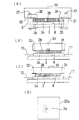
まず、図1および図2(A)に示すように、ゲル状の寒天フィルム24をセンサ部3のセンサ面8に接触するようにして設ける。この寒天フィルム24は、例えばpH7に調整された0.1Mの塩化カリウム溶液に1.5%の寒天を加えて加熱し、固化させてなるもので、その厚みは0.5〜1mm程度である。つまり、この実施の形態においては、センサ面8上に設けられる液体層としてゲル化溶液を用いている。なお、図2(A)において、25はゲル化溶液24と同程度の厚みを有するシリコン製のスペーサで、ゲル化溶液24の周囲に配置されている。また、26は上部ホルダ、27はねじ部材である。
【0020】
次いで、前記ゲル化溶液24の上面に評価対象であるイオン交換膜28を載せる(図1および図2(A)参照)。
【0021】
そして、前記イオン交換膜28の上方からゲル化溶液24とはpH値が異なる溶液(例えば酸液)29を滴下する(図1および図2(B)参照)。
【0022】
上述のようにして、イオン交換膜28上に滴下されたある所定のpH値を有する溶液29は、時間が経過するに伴ってイオン交換膜28を透過し、さらに、ゲル化溶液24に侵入し、その内部に透過し、拡散し(図2(C)参照)、ゲル化溶液24にpHの変化が生ずる。このpH変化は、微小な領域でのみ計測できるものであり、前記光走査型二次元濃度分布測定装置1によって検出可能な変化である。
【0023】
すなわち、図1および図2(B),(C)に示すように、対極10、比較電極11を、ゲル化溶液24に到達するように装着し、半導体基板6に空乏層が発生するように、ポテンショスタット16からの直流電圧を比較電極11とオーミック電極12との間に印加して、半導体基板6に所定のバイアス電圧を印加する。この状態で半導体基板6に対してレーザ光4を一定周期(例えば、10kHz)で断続的に照射することによって半導体基板6に交流光電流を発生させる。このレーザ光4の断続照射は、コンピュータ20の制御信号がインタフェースボード19を介して入力されることによって行われる。前記光電流は、半導体基板6の照射点に対向する点で、センサ面8に接しているゲル化溶液24におけるpHを反映した値であり、その値を測定することにより、この部分でのpH値を知ることができる。
【0024】
さらに、センサ部走査装置13によって、センサ部3を二次元方向(X,Y方向)に移動させることにより、半導体基板6にはレーザ光4が二次元方向に走査されるようにして照射され、ゲル化溶液24における位置信号(X,Y)と、その場所で観測された交流光電流値により、表示装置22の画面22a上に、図2(D)に示すように、ゲル化溶液24に形成されるpH分布の状態を表す二次元画像30が表示される。
【0025】
前記画像表示は、例えば次のようにして行われる。今、イメージサイズが1cm×2cmとし、ピクセルサイズが100μmであるとすると、各測定点(100×200)でのpH値は、測定点の位置座標に対応して並べられる。並べられた値は、グレースケールまたはカラースケールに対応させて、例えばSTM(走査型トンネル顕微鏡)像に類する化学画像30として表示される。
【0026】
そして、前記コンピュータ20においては、イオン交換膜28上にあるpH値を有する溶液29を滴下してからそのpH値がセンサ面8によって検出されるまでの時間や、一定時間後に形成されるpH変化領域のサイズや、pH変化領域内にさらに生じているpH分布などを解析することができる。
【0027】
上述の説明から理解されるように、この発明のイオン交換膜の評価方法で用いる光走査型二次元濃度分布測定装置1は、微小な領域における微小なpH変化をも的確にしかも迅速に把握することができ、これを画像処理して表示装置22の画面22a上に二次元画像30として表示することができる。したがって、この発明のイオン交換膜の評価方法によれば、従来に比べて簡便にしかも迅速にイオン交換膜28の評価を行うことができる。
【0028】
すなわち、ゲル化溶液24におけるpH分布を観察することにより、イオン交換膜28内におけるプロトンの動きを観察することができ、これに基づいて、イオン交換膜28におけるイオン交換の状態を評価することができ、イオン交換膜28の交換能力や交換速度を定量的に評価することができ、それらを評価する指標を得ることができる。言い換えれば、イオン交換膜28をその実体に即して直接的に評価することができ、したがって、イオン交換膜28を精度よく確実に評価することができる。
【0029】
そして、上記イオン交換膜の評価方法においては、微小な領域における微小なpH変化をも的確にしかも迅速に把握することができ、これを画像処理して表示装置22の画面22a上に二次元画像30として表示するものであるので、イオン交換膜28をその部位ごとに測定することができ、より細かな評価を行うことができる。
【0030】
図3および図4は、この発明の第2の実施の形態を示すもので、この実施の形態において用いる光走査型二次元濃度分布測定装置は、上記第1の実施の形態において用いたものと変わるところがなく、図3および図4に示すように、イオン交換膜28に適宜の直流電圧を印加するようにしている点が異なるだけである。
【0031】
すなわち、図3および図4において、31,32はアノード、カソードで、それぞれ直流電源33に接続されている。これらの電極31,32は、ゲル化溶液24上に載置されるイオン交換膜28の左右両端部に接触するように設けられ、イオン交換膜28に適宜の直流電圧(例えば3V〜9V程度)を印加するものである。なお、図4において、34は表示装置22の画面22a上に表示される二次元画像である。
【0032】
この実施の形態においては、イオン交換膜28上にあるpH値を有する溶液29を滴下してからイオン交換膜28において生ずるプロトンの動きを観察するに際して、イオン交換膜28に所定の直流電圧を印加する点が異なるだけで、その動作については、上記第1の実施の形態の動作と同様であるので、詳細については省略する。
【0033】
この実施の形態においては、上記第1の実施の形態の作用効果に加えて、イオン交換膜28内のプロトンの動きをより確実に観察することができるといった利点がある。
【0034】
なお、上述の二次元イオン濃度測定装置1において、比較電極11を省略し、対極10を介してバイアス電圧を印加してもよい。但し、比較電極11を設けていた場合の方が半導体基板6にバイアス電圧をより安定に印加することができる。
【0035】
そして、上記各光走査型二次元濃度分布測定装置において、センサ部3をX,Y方向に移動させるのに代えて、光照射部5に光照射部走査装置を設け、光照射部5をX,Y方向に移動させるようにしてもよく、また、光照射部5とセンサ部3との間にレーザ光走査装置を設け、レーザ光4をX,Y方向に移動させるようにしてもよい。
【0036】
さらに、上記光走査型二次元濃度分布測定装置においては、光照射部5によるレーザ光4を半導体基板6のセンサ面8とは反対側から照射するようにしていたが、これに代えて、センサ面8側から照射するようにしてもよい。そして、光照射部5として、例えば特願平7−39114号に示すように、半導体基板6に組み込まれた光照射部を採用してもよい。
【0037】
【発明の効果】
この発明のイオン交換膜の評価方法によれば、従来に比べて簡便にしかも迅速に評価を行うことができ、イオン交換膜を効率よくしかも確実に評価することができる。また、上記イオン交換膜の評価方法は、再現性に優れている。
【図面の簡単な説明】
【図1】第1の実施の形態に用いる装置の全体構成を概略的に示す図である。
【図2】前記実施の形態におけるイオン交換膜の評価方法を説明するための図である。
【図3】第2の実施の形態に用いる装置の全体構成を概略的に示す図である。
【図4】前記実施の形態におけるイオン交換膜の評価方法を説明するための図である。
【図5】従来技術を説明するための図である。
【符号の説明】
1…光走査型二次元濃度分布測定装置、4…光、6…半導体基板、8…センサ面、24…液体層、28…イオン交換膜、29…液体。[0001]
BACKGROUND OF THE INVENTION
The present invention relates to a method for evaluating an ion exchange membrane.
[0002]
[Prior art]
Conventionally, it may be said that there is no method for observing the movement of ions in the ion exchange membrane, and as shown in FIG. 5, the
[0003]
[Problems to be solved by the invention]
However, in the conventional method described above, when the
[0004]
The present invention has been made in consideration of the above-mentioned matters, and an object of the present invention is to provide an ion exchange membrane evaluation method capable of evaluating an ion exchange membrane simply, quickly and accurately. It is to be.
[0005]
[Means for Solving the Problems]
In order to achieve the above object, an ion exchange membrane evaluation method according to the present invention has a sensor surface on one surface of a semiconductor substrate, and is configured to irradiate the semiconductor substrate with light. A liquid layer is provided so as to be in contact with the sensor surface of the concentration distribution measuring apparatus, and an ion exchange membrane to be evaluated is provided so as to be in contact with the liquid layer. In this state, a liquid having a pH value different from that of the liquid layer is provided. It is characterized in that the ion exchange membrane is dropped on the ion exchange membrane and the ion exchange membrane is evaluated based on the change in pH in the liquid layer.
[0006]
In the ion exchange membrane evaluation method, it is preferable to use a gel such as an agar gel or polyacrylamide gel as the liquid layer. In addition, the change in pH is grasped by analyzing the time until a region having a different pH is detected, the size of the pH region formed after a certain time, the pH value further generated in the pH change region, and the like. can do.
[0007]
In the ion exchange membrane evaluation method of the present invention, for example, by observing the movement of protons in the ion exchange membrane when an acid solution is dropped on the ion exchange membrane, using an optical scanning type two-dimensional concentration distribution measuring device, The reaction of the exchange membrane can be observed visually, and the exchange ability and exchange rate of the ion exchange membrane can be grasped numerically based on the change in pH in the liquid layer.
[0008]
And, in the ion exchange membrane evaluation method of the present invention, since only a liquid having a pH different from the pH of the liquid layer is dropped, the ion exchange can be evaluated more easily and quickly than in the past. Can do.
[0009]
In the ion exchange membrane evaluation method of the present invention, when observing a change in pH in the liquid layer, a predetermined DC voltage may be applied to the ion exchange membrane (Claim 2). The movement of protons in the ion exchange membrane can be observed more reliably.
[0010]
DETAILED DESCRIPTION OF THE INVENTION
1 and 2 show a first embodiment of the present invention. First, an optical scanning type two-dimensional concentration
[0011]
In FIG. 1,
[0012]
The
[0013]
[0014]
[0015]
The
[0016]
[0017]
[0018]
Next, an ion exchange membrane evaluation method using the optical scanning type two-dimensional concentration
[0019]
First, as shown in FIGS. 1 and 2A, a gel-
[0020]
Next, an
[0021]
Then, a solution (for example, an acid solution) 29 having a pH value different from that of the gelling
[0022]
As described above, the
[0023]
That is, as shown in FIG. 1 and FIGS. 2B and 2C, the
[0024]
Further, by moving the
[0025]
The image display is performed as follows, for example. Now, assuming that the image size is 1 cm × 2 cm and the pixel size is 100 μm, the pH values at the respective measurement points (100 × 200) are arranged corresponding to the position coordinates of the measurement points. The arranged values are displayed as a chemical image 30 similar to an STM (scanning tunneling microscope) image, for example, corresponding to a gray scale or a color scale.
[0026]
In the
[0027]
As understood from the above description, the optical scanning two-dimensional concentration
[0028]
That is, by observing the pH distribution in the gelled
[0029]
In the ion exchange membrane evaluation method, a minute pH change in a minute region can be accurately and quickly grasped, and this is image-processed to form a two-dimensional image on the
[0030]
3 and 4 show a second embodiment of the present invention. The optical scanning type two-dimensional concentration distribution measuring apparatus used in this embodiment is the same as that used in the first embodiment. There is no change, and the only difference is that an appropriate DC voltage is applied to the
[0031]
That is, in FIGS. 3 and 4,
[0032]
In this embodiment, when observing the movement of protons generated in the
[0033]
In this embodiment, in addition to the operational effects of the first embodiment, there is an advantage that the movement of protons in the
[0034]
In the two-dimensional ion
[0035]
In each of the optical scanning type two-dimensional concentration distribution measuring apparatuses, instead of moving the
[0036]
Further, in the optical scanning type two-dimensional concentration distribution measuring apparatus, the
[0037]
【The invention's effect】
According to the method for evaluating an ion exchange membrane of the present invention, the evaluation can be performed more easily and quickly than in the prior art, and the ion exchange membrane can be evaluated efficiently and reliably. Moreover, the ion exchange membrane evaluation method is excellent in reproducibility.
[Brief description of the drawings]
FIG. 1 is a diagram schematically showing an overall configuration of an apparatus used in a first embodiment.
FIG. 2 is a diagram for explaining an ion exchange membrane evaluation method in the embodiment.
FIG. 3 is a diagram schematically showing an overall configuration of an apparatus used in a second embodiment.
FIG. 4 is a diagram for explaining an ion exchange membrane evaluation method in the embodiment.
FIG. 5 is a diagram for explaining a conventional technique.
[Explanation of symbols]
DESCRIPTION OF
Claims (2)
Priority Applications (1)
| Application Number | Priority Date | Filing Date | Title |
|---|---|---|---|
| JP18962099A JP3667566B2 (en) | 1999-07-02 | 1999-07-02 | Ion exchange membrane evaluation method |
Applications Claiming Priority (1)
| Application Number | Priority Date | Filing Date | Title |
|---|---|---|---|
| JP18962099A JP3667566B2 (en) | 1999-07-02 | 1999-07-02 | Ion exchange membrane evaluation method |
Publications (2)
| Publication Number | Publication Date |
|---|---|
| JP2001021531A JP2001021531A (en) | 2001-01-26 |
| JP3667566B2 true JP3667566B2 (en) | 2005-07-06 |
Family
ID=16244355
Family Applications (1)
| Application Number | Title | Priority Date | Filing Date |
|---|---|---|---|
| JP18962099A Expired - Fee Related JP3667566B2 (en) | 1999-07-02 | 1999-07-02 | Ion exchange membrane evaluation method |
Country Status (1)
| Country | Link |
|---|---|
| JP (1) | JP3667566B2 (en) |
-
1999
- 1999-07-02 JP JP18962099A patent/JP3667566B2/en not_active Expired - Fee Related
Also Published As
| Publication number | Publication date |
|---|---|
| JP2001021531A (en) | 2001-01-26 |
Similar Documents
| Publication | Publication Date | Title |
|---|---|---|
| Martin et al. | Scanning electrochemical microscopy: theory and experiment for the positive feedback mode with unequal diffusion coefficients of the redox mediator couple | |
| Das et al. | A high-speed, flexible-scanning chemical imaging system using a light-addressable potentiometric sensor integrated with an analog micromirror | |
| Qin et al. | Label‐Free Electrochemical Imaging of Latent Fingerprints on Metal Surfaces | |
| JPWO2008152712A1 (en) | Nano particle measuring device | |
| Das et al. | Analog micromirror-LAPS for chemical imaging and zoom-in application | |
| JP3667566B2 (en) | Ion exchange membrane evaluation method | |
| JP3688096B2 (en) | Material evaluation method | |
| JPH09281066A (en) | Measuring system using impedance ct | |
| US11264199B2 (en) | Electrochemical measurement of electron beam-induced pH change during liquid cell electron microscopy | |
| JP3434124B2 (en) | Evaluation method of microcapsules | |
| JP3098429B2 (en) | Optical scanning type two-dimensional concentration distribution measuring device | |
| JPH1123533A (en) | Light scanning type two-dimensional concentration distribution measuring device | |
| JP2001183321A (en) | Method for evaluating photocatalytic film | |
| JP2000162080A (en) | Evaluation method for leak of liquid or gas in material | |
| JP3229812B2 (en) | Calibration method of optical scanning type two-dimensional pH distribution measuring device | |
| JP3058588B2 (en) | pH image color display method and apparatus | |
| JPH1010087A (en) | Calibrating method for optical scanning type two-dimensional concentration distribution measuring device | |
| Zhou et al. | Non-invasive, real-time and dynamic monitoring of CO2 and O2 simultaneously using modulated potential pulse-amperometry/coulometry | |
| JPH10113199A (en) | Optoscanning two-dimensional concentration distribution measurement | |
| JP2000206084A (en) | Optical scanning two-dimensional concentration distribution measuring apparatus | |
| JPH09297106A (en) | Ion exchanger evaluation method | |
| JPH08320301A (en) | Concentration distribution-measuring apparatus of a plurality of dissolved substances | |
| JPH09292358A (en) | Zeta-potential measuring method using optical-scanning type two-dimensional concentration-distribution measuring device | |
| JPH1175891A (en) | Measurement of activity of microorganism and device therefor | |
| JPH11148917A (en) | Calibration of optical scanning two-dimensional concentration distribution measuring apparatus |
Legal Events
| Date | Code | Title | Description |
|---|---|---|---|
| A977 | Report on retrieval |
Free format text: JAPANESE INTERMEDIATE CODE: A971007 Effective date: 20050228 |
|
| TRDD | Decision of grant or rejection written | ||
| A01 | Written decision to grant a patent or to grant a registration (utility model) |
Free format text: JAPANESE INTERMEDIATE CODE: A01 Effective date: 20050329 |
|
| A61 | First payment of annual fees (during grant procedure) |
Free format text: JAPANESE INTERMEDIATE CODE: A61 Effective date: 20050406 |
|
| R150 | Certificate of patent (=grant) or registration of utility model |
Free format text: JAPANESE INTERMEDIATE CODE: R150 |
|
| FPAY | Renewal fee payment (prs date is renewal date of database) |
Free format text: PAYMENT UNTIL: 20110415 Year of fee payment: 6 |
|
| FPAY | Renewal fee payment (prs date is renewal date of database) |
Free format text: PAYMENT UNTIL: 20110415 Year of fee payment: 6 |
|
| LAPS | Cancellation because of no payment of annual fees |