JP3665680B2 - Trace analysis method and liquid chromatograph - Google Patents
Trace analysis method and liquid chromatograph Download PDFInfo
- Publication number
- JP3665680B2 JP3665680B2 JP14304796A JP14304796A JP3665680B2 JP 3665680 B2 JP3665680 B2 JP 3665680B2 JP 14304796 A JP14304796 A JP 14304796A JP 14304796 A JP14304796 A JP 14304796A JP 3665680 B2 JP3665680 B2 JP 3665680B2
- Authority
- JP
- Japan
- Prior art keywords
- mixer
- sample
- tube
- injector
- diluent
- Prior art date
- Legal status (The legal status is an assumption and is not a legal conclusion. Google has not performed a legal analysis and makes no representation as to the accuracy of the status listed.)
- Expired - Fee Related
Links
Images


Description
【0001】
【発明の属する技術分野】
本発明は、例えば自動車排出ガス中のアルデヒドの微量分析に好適で、試料と希釈液とを十分に混合し、希釈効率を高めるとともに濃縮効率を向上して、試料の有効利用と分離精度の向上を図り、しかも複数の溶出液またはこれと反応試薬とを十分かつ効率良く混合して、微量成分を高感度に分析できるようにした微量分析方法および液体クロマトグラフに関する。
【0002】
【従来の技術】
液体クロマトグラフによる試料の微量分析に際しては、一般に試料を大量に注入するとともに、試料を所定濃度に希釈し、濃縮コンディションを整えた上で濃縮過程に送出し、該過程の濃縮カラムで濃縮後、これを溶出して分析カラムで分離するようにしている。
【0003】
例えば、特開平4ー359148号公報には、希釈液に連通する送液ラインにインジェクターを接続し、該ラインに二つの三方ジョイントを離間して接続し、これらのジョイント間に希釈ラインを接続する一方、送液ラインの下流に六方切換弁を接続し、該弁の二つのポート間に濃縮ラインを接続するとともに、前記弁に分析ラインと溶出液ラインとを接続し、試料の大量注入時に希釈液を送液ラインと希釈ラインとに供給し、希釈した試料を濃縮カラムで濃縮し蓄積した後、濃縮ラインに溶出液を供給し、前記濃縮した試料を溶出して分析ラインに送出し、これを分析カラムで分離している。
【0004】
しかし、この分析法は試料と希釈液との混合が不十分のまま濃縮ラインに送出しているため、濃縮カラムの濃縮効率が低く、試料の空費や濃縮時間の増大を招く上に分析カラムでの分離精度が悪く、クロマトグラムのピークがブロードになったり、ピーク高さが低くなって、十分な分析感度を得られない等の問題があった。
【0005】
【発明が解決しようとする課題】
本発明はこのような問題を解決し、例えば自動車排出ガス中のアルデヒドの微量分析に好適で、試料と希釈液とを十分に混合し、希釈効率を高めるとともに濃縮効率を向上して、試料の有効利用と分離精度の向上を図り、しかも複数の溶出液またはこれと反応試薬とを十分かつ効率良く混合して、微量成分を高感度に分析できるようにした微量分析方法および液体クロマトグラフを提供することを目的とする。
【0006】
【課題を解決するための手段】
このため、請求項1の発明は、希釈液をインジェクターに送出し、該インジェクターで注入した試料を希釈液と共に濃縮カラムに送出し、該カラムで試料を濃縮する微量分析方法において、インジェクターの下流側にミキサーを配置し、該ミキサーを介して試料と希釈液とを混合し、試料を一様な濃度に希釈調製して濃縮カラムに送出し、濃縮カラムにおける試料の吸着ないし濃縮効率を向上し、試料の有効利用と分離精度の向上を図り、微量成分を高感度に分析できるようにしている。
【0007】
請求項2の発明は、希釈液をインジェクターに送出するとともに、所定量の希釈液をインジェクターの下流側に送出し、該希釈液をインジェクターで注入した試料と希釈液とに合流し、これらを濃縮カラムに送出して試料を濃縮する微量分析方法において、希釈液の合流位置またはその下流側にミキサーを配置し、該ミキサーを介して試料と双方の希釈液とを混合し、試料を大量の希釈液で一様な濃度に希釈調製し、これを濃縮カラムに送出して、濃縮カラムにおける試料の吸着ないし濃縮効率を向上し、試料の有効利用と分離精度の向上を図り、試料の大量注入と微量成分の高感度分析を可能にしている。
【0008】
請求項3の発明は、ミキサーが、内部に複数の螺旋状の通路と、各通路に連通する間隙とを有し、前記通路を介して二次流を強化し、流れと垂直方向の混合を促して、同方向の濃度勾配を維持させるとともに、間隙を介して当該部を移動する液体を近接または離間する通路に進入させ、液体の流速および流量の均一化を図ることで、脈流の影響を軽減し高感度分析を可能にしている。
【0009】
請求項4の発明は、希釈液をインジェクターに送出し、該インジェクターで注入した試料を希釈液と共に濃縮カラムに送出し、該カラムで試料を濃縮するとともに、同種または異種の複数の溶出液をグラジェントミキサーを介して混合し、この混合溶出液を濃縮カラムに送出する微量分析方法において、希釈液の合流位置またはその下流側にミキサーを配置し、該ミキサーを介して試料と双方の希釈液とを混合し、これを濃縮カラムに送出するとともに、前記グラジェントミキサーを介して、複数の溶出液を強制的に撹拌するとともに、該撹拌の後に複数の溶出液を流速に応じて撹拌するようにして、複数の溶出液を十分かつ効率良く混合し、微量成分を高感度に分析できるようにしている。
【0010】
請求項5の発明は、前記グラジェントミキサーは、溶出液を強制的に撹拌するダイナミックミキサー部と、流速に応じて撹拌するスタティックミキサー部とを備え、複数の溶出液を十分かつ効率良く混合し得るようにしている。
【0011】
請求項6の発明は、希釈液をインジェクターに送出し、該インジェクターで注入した試料を希釈液と共に濃縮カラムに送出し、該カラムで試料を濃縮するとともに、分析カラムと検出器との間の分析管に反応試薬を供給可能な反応ミキサーを配置する微量分析方法において、インジェクターの下流側にミキサーを配置し、該ミキサーを介して試料と希釈液とを混合し、これを濃縮カラムに送出するとともに、前記反応ミキサーは内部に複数の螺旋状の通路と、各通路に連通する間隙とを有し、溶出液と反応試薬とを十分かつ効率良くミキシングさせて、それらの反応率を高め、分離感度を向上するようにしている。
【0012】
請求項7の発明は、反応ミキサーを分析管に着脱可能に配置し、分離感度の調整を簡便に行えるようにしている。
【0013】
請求項8の発明は、微量分析方法が自動車排出ガス中のアルデヒド分析であり、この種の分析の感度向上と、試料の大量注入による分析の能率向上を図るようにしている。
【0014】
請求項9の発明は、試料の分析後に洗浄液を送出し、少なくともミキサーと濃縮カラム系統とを洗浄して、不純物成分の現出を防止するとともに、再現性を確保して、不純物を多量に含む自動車排出ガス中のアルデヒド分析に好適にしている。
【0015】
請求項10の発明は、一端を希釈液に連通し他端を切換弁に接続した送液管と、送液管に介挿し試料を注入するインジェクターと、切換弁に両端を接続した濃縮管と、濃縮管に介挿した濃縮カラムとを備えた液体クロマトグラフにおいて、インジェクターと切換弁との間にミキサーを配置し、濃縮カラムにおける試料の吸着ないし濃縮効率を向上し、試料の有効利用と分離精度の向上を図り、微量成分を高感度に分析できるようにしている。
【0016】
請求項11の発明は、一端を希釈液に連通し他端を切換弁に接続した送液管と、送液管に介挿し試料を注入するインジェクターと、切換弁に両端を接続した濃縮管と、濃縮管に介挿した濃縮カラムと、インジェクターを挟んで両端を送液管に接続した希釈管とを備えた液体クロマトグラフにおいて、インジェクターより下流側の送液管と希釈管との接続部または該接続部の下流側にミキサーを配置し、試料を大量の希釈液で一様な濃度に希釈調製し、これを濃縮カラムに送出して、濃縮カラムにおける試料の吸着ないし濃縮効率を向上し、試料の有効利用と分離精度の向上を図り、試料の大量注入と微量成分の高感度分析を可能にしている
【0017】
請求項12の発明は、ミキサーが、内面に複数のリード溝を螺旋状に形成した外筒と、周面に複数のリード溝を螺旋状に形成し、かつ前記外筒に挿入可能な内筒とを有し、これらのリード溝によって二次流を強化し、流れと垂直方向の混合を促して、同方向の濃度勾配を維持させ、精密かつ十分なミキシングを可能にしている。
【0018】
請求項13の発明は、ミキサーが、外筒のリード溝と、内筒の周面およびリード溝との間に、種々の断面形状および断面積の螺旋状の通路を複数設け、前記通路を介して二次流を強化するとともに、多様な二次流を形成して、流れと垂直方向の混合を促し、同方向の濃度勾配を維持させて、精密かつ十分なミキシングを可能にしている。
【0019】
請求項14の発明は、ミキサーが、内筒の外径を外筒の内径よりも小径に形成し、これら内外筒の間に微小な間隙を形成して、前記通路の他に間隙による流体通路を設け、前記通路と相俟って十分かつ精密なミキシングを可能にしている。
【0020】
請求項15の発明は、ミキサーが、前記間隙を前記通路に連通可能にし、間隙を介し当該部を移動する液体を近接または離間する通路に進入させ、液体の流速および流量の均一化を図ることで、脈流の影響を軽減し高感度分析を可能にしている。
【0021】
請求項16の発明は、一端を希釈液に連通し他端を切換弁に接続した送液管と、送液管に介挿し試料を注入するインジェクターと、前記切換弁に両端を接続した濃縮管と、濃縮管に介挿した濃縮カラムと、一端が複数の溶出液導管に連通し他端が切換弁に連通する混合管と、該混合管に介挿したグラジェントミキサーとを備えた液体クロマトグラフにおいて、インジェクターと切換弁との間にミキサーを配置するとともに、前記グラジェントミキサーは、溶出液を強制的に撹拌するダイナミックミキサー部と、流速に応じて撹拌するスタティックミキサー部とを備え、複数の溶出液を十分かつ効率良く混合し、微量成分を高感度に分析できるようにしている。
【0022】
請求項17の発明は、前記スタティックミキサー部は、前記ミキサーと同一構造に構成し、溶出液の混合精度を高めるとともに、ミキサーの互換性を図り、その製造とメインテナンスの合理化を図れるようにしている。
【0023】
請求項18の発明は、一端を希釈液に連通し他端を切換弁に接続した送液管と、送液管に介挿し試料を注入するインジェクターと、前記切換弁に両端を接続した濃縮管と、濃縮管に介挿した濃縮カラムと、インジェクターを挟んで両端を送液管に接続した希釈管と、前記切換弁に接続し、かつ分離カラムと検出器との間に反応試薬を供給可能な反応ミキサーを配置した分析管と、該管を備えた液体クロマトグラフにおいて、インジェクターより下流側の送液管と希釈管との接続部または該接続部の下流側にミキサーを配置するとともに、前記反応ミキサーは内部に複数の螺旋状の通路と、各通路に連通する間隙とを有し、溶出液と反応試薬とを十分かつ効率良くミキシングさせて、それらの反応率を高め、分離感度を向上するようにしている。
【0024】
請求項19の発明は、前記反応ミキサーを分析管に着脱可能に配置し、分離感度の調整を簡便に行えるようにしている。
【0025】
【発明の実施の形態】
以下、本発明を液体クロマトグラフによるグラジェント分析に適用した図示の実施の形態について説明すると、図1は自動車排出ガスに含まれるアルデヒドの分析系を示し、同図において1は液体クロマトグラフのカラムオーブンで、該オーブン1の内部に、カラムスイッチングである回転操作型の六方切換弁2が設けられている。
【0026】
六方切換弁2は外部に連通する6つのポートP1 〜P6 を備え、このうちポートP1 に送液管3の一端が接続され、ポートP2 とポートP5 とに濃縮管4の両端が接続され、またポートP3 に分析管5の一端が接続され、ポートP4 に混合管6の一端が接続され、ポートP6 に排出管7の一端が接続されている。
【0027】
送液管3の他端は、希釈液収納容器8に収容した水等の希釈液9に連通し、該管3の上流側に希釈液9の送液ポンプ10が接続されている。希釈液収納容器8と送液ポンプ10との間には切換弁11が介挿され、該弁11に洗浄管12の一端が接続され、該管12の他端が洗浄液収容容器13に収容した洗浄液14に連通している。
【0028】
送液ポンプ10よりも下流側の送液管3には、三方弁15が接続され、該弁15の下流側にDNPH(2,4ジニトロフェニルヒドラジン)アルデヒド類を含む試料を注入するインジェクター16が接続されている。
インジェクター16の下流側には三方弁17が接続され、該弁17の直近の下流側に円筒状のミキサー18が接続されている。
【0029】
この場合、ミキサー18を三方弁17と同位置に配置したり、この両者を一体に構成することも可能であり、そのように構成することで、三方弁17とミキサー18との間のデッドボリュームの増大を回避し、流れ方向に垂直な方向の濃度勾配を維持して、精密かつ十分なミキシングを実現できるとともに、部品点数の低減とそれらの取付け作業の手間を軽減する。
【0030】
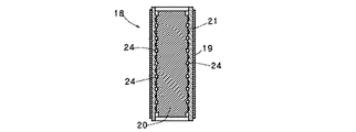
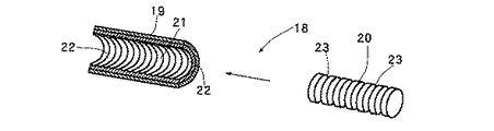
ミキサー18は、液体をその流速に応じて撹拌可能な、いわゆるスタティックミキサーで構成され、これは図2〜図4のように金属製の外筒19と、該筒19に挿入可能な金属製の内筒20とで構成され、このうち外筒19の内部に、ステンレス製のミキサーチューブ21が一体に装着されている。
【0031】
この場合、生体試料(バイオ)分析時に金属製の外筒19と内筒20とミキサーチューブ21とを使用すると、上記試料が析出し変成するので、金属製以外の例えば高硬度の合成樹脂、またはセラミックス、若しくはテフロン製のものを使用することが望ましい。
【0032】
ミキサーチューブ21の内面には、リード溝22が軸方向に沿って螺旋状に形成され、該溝22は略円弧状断面に形成されていて、そのピッチpは軸方向に微小量漸減または漸増して形成されている。
【0033】
内筒20は円筒状に形成され、その外径dはミキサーチューブ21の内径Dよりも小径に形成され、それらの間に試料と希釈液9との混合液の流路となる微小な間隙eを形成している。
【0034】
また、内筒20の周面にはリード溝23が軸方向に沿って螺旋状に形成され、該溝23は略円弧状断面に形成されていて、その溝幅は前記リード溝22と略等幅に形成され、かつそのピッチPは前記ピッチpよりも大きく、軸方向に等ピッチに形成されている。
【0035】
この場合、リード溝22のピッチpを等ピッチに形成し、リード溝23のピッチPを軸方向に漸増または漸減してもよく、そのようにすることで内側に不規則なピッチで成形するリード溝22に比べて、リード溝23の成形が容易になる。
【0036】
更には、双方のピッチp,Pを軸方向に漸増または漸減することも可能であり、そのようにすることで相対するリード溝22,23で形成する溶液の通路24の断面形状および断面積を多様に変化させ、ミキシングの効果と効率を向上することができる。
【0037】
三方弁15,17の間には希釈管25が接続され、該管25の上流側に抵抗設定器26が接続されている。抵抗設定器26には、種々の管路抵抗を有する複数の抵抗管27の一端が接続され、それらの抵抗管27を選択的に切換え可能にしている。
各抵抗管27の他端は、7つのポートを備えたジョイント28に接続され、該ジョイント28に希釈管25が接続されている。
【0038】
濃縮管4には濃縮カラム29が接続され、また分析管5の他端はドレン(排出口)に連通していて、該管5に分析カラム30が接続され、該カラム30の下流側に検出器31が介挿されている。
【0039】
混合管6の他端にはグラジェントミキサー32が接続され、該ミキサー32に複数の溶出液導管33,34の下流側端部が接続され、それらの上流側端部が溶出液収納容器35,36に収容した異種の溶出液37,38に連通している。
【0040】
グラジェントミキサー32は、液体を強制的に撹拌可能な、いわゆるダイナミックミキサー部と、液体を流速に応じて撹拌可能な、いわゆるスタティックミキサー部とを一体に組み付け、かつそれらの流路を直列に接続して構成している。このうち、スタティックミキサー部はダイナミックミキサー部の下流側に配置され、またこのスタティックミキサーは、前記ミキサー18と同一のものが使用されている。
【0041】
ダイナミックミキサー部は単一の狭小なミキシング室を備え、該室内に回転速度を0〜500rpmの範囲で調整可能な撹拌子を有している。
したがって、ダイナミックミキサー部は、撹拌子が零回転のときはスタティックミキサーとして機能する。
【0042】
実施形態の場合、溶出液37に10%THF(テトラヒドロフラン)が使用され,溶出液38にCH3 CN(アセトニトリル)が使用され、これらを各送液ポンプ39,40を介して、前記ミキサー32へ供給可能にしている。
【0043】
送液ポンプ39,40は、種々の分析条件およびグラジェントプログラムに基いて、それぞれの吐出量を制御可能にされ、溶出液37,38の所定の混合比を形成可能にしている。
なお、溶出液導管33,34のミキサー接続口に、各溶出液31,32の逆流を防止する逆止弁を設置することが望ましい。
【0044】
この他、図において41は分析カラム30と、検出器31との間の分析管5に着脱可能に接続した反応ミキサーで、前記ミキサー18と同様に構成され、該ミキサー41は溶出液との反応率を高め分離感度を改善する際に装着される。
反応ミキサー41には、反応試薬収納容器42に連通する薬液導管43が接続され、上記容器42に収容した反応試薬44を、送液手段である送液ポンプ45を介して上記ミキサー41に供給し、分析管5内を移動する溶出液37,38に添加可能にしている。
【0045】
このように構成した液体クロマトグラフは、三方弁17の直近の下流側にミキサー18を配置しているが、分析に悪影響を与えるデッドボリュームの増加を僅少に抑えているから、後述のような十分かつ効率良いミキシング効果を得られる
【0046】
この場合、ミキサー18を三方弁17と同位置に配置したり、この両者を一体に構成すれば、三方弁17とミキサー18との間のデッドボリュームが低減され、ミキサー18による流れ方向に垂直な方向の濃度勾配を維持でき、精密かつ十分なミキシング効果を得られるとともに、部品点数の低減とそれらの取付け作業の手間を軽減する。
【0047】
次に図1の分析系において、自動車排出ガス中のアルデヒドを分析する場合は、切換弁11を操作し、送液管3を希釈液9に連通する一方、洗浄管12を閉塞する。
また、三方弁15,17を操作し、送液ポンプ10とインジェクター16とミキサー18とを連通し、希釈管19の両端を閉塞する。
【0048】
更に、六方切換弁2を操作し、ポートP1 とポートP2 、ポートP3 とポートP4 、ポートP5 とポートP6 とを、それぞれ連通させる。
このようにすると、送液管3がポートP1 ,P2 を介して濃縮管4に連通し、該管4の下流側端部がポートP5 ,P6 を介して排出管7に連通する。
また、溶出液導管33,34がミキサー32に連通し、混合管6がポートP4 ,P3 を介して分析管5に連通し、検出器31よりドレインに連絡する。
【0049】
このような状況の下で送液ポンプ10を駆動すると、希釈液収納容器8内の希釈液9が汲み上げられ、これが送液管3に導かれてインジェクター16に送られる。
インジェクター16では、DNPH(2,4ジニトロフェニルヒドラジン)アルデヒドを含む試料が注入され、これが希釈液9に混入して三方弁17からミキサー18に導かれる。
【0050】
ミキサー18では、試料と希釈液9との混合液が、ミキサーチューブ21のリード溝22と、内筒20の周面またはリード溝23とで区画された通路24に沿って、内筒20の周囲を螺旋状に移動し、この移動過程で二次流、つまり流れの方向と垂直方向に作用する流れの影響を受けて同方向の混合を促され、同方向における試料の濃度勾配を維持する。
【0051】
この場合、上記通路24は図2のように、内筒20の周囲に多数形成されているから二次流が強化され、上記濃度勾配が維持されるとともに、これらの通路24は図示のように種々の断面積と断面形状に形成され、その曲率半径を厳密に相違させているから、多様な二次流を得られる。
【0052】
したがって、上記混合液は、長路に亙り二次流による混合作用を受けて精密にミキシングされ、希釈液9中の試料濃度が均一化するとともに、その流量ないし流速を変化して移動し、多様な二次流によって前記濃度勾配の維持を増進する。
しかも、通路24を移動する混合液の一部は、間隙eを擦り抜けて隣接または離間する他の通路24に流入し、混合液の流量および流速の一様化を促して、脈流の影響を軽減する。
【0053】
こうしてミキシングされた混合液は、前記濃度勾配を維持して六方切換弁2に流入し、該切換弁2のポートP1 よりポートP2 を経て濃縮管4を矢視方向へ移動し、濃縮カラム29で試料を濃縮し蓄積される。
【0054】
この場合、混合液は前述のように精密にミキシングされ、試料濃度が均一化されているから、上記カラム29に試料が効率良く濃縮され、ミキシング不全による試料の濃縮不全や空費を防止する。
濃縮後、混合液は六方切換弁2に戻り、そのポートP5 よりポートP6 を経て排出管7を移動し、排出される。
【0055】
一方、前記試料の濃縮と前後して、グラジェントミキサー32のダイナミックミキサー(図示略)部を駆動し、該ミキサーの撹拌子を回転するとともに、送液ポンプ39,40を駆動する。
送液ポンプ39,40を駆動すると、溶出液収納容器35,36内の溶出液37,38が汲み上げられ、これらが溶出液導管33,34を経てグラジェントミキサー32に導かれる。
【0056】
溶出液37,38は、グラジェントミキサー32内のダイナミックミキサー部で強制的かつ迅速に撹拌されて、スタティックミキサー部へ移動し、該ミキサー部で内筒の周面またはリード溝に沿って、内筒の周面を螺旋状に移動し、この移動過程で二次流、つまり流れの方向と垂直方向の混合を促され、その濃度勾配を維持する。
【0057】
そして、このダイナミックおよびスタティックミキサー部で十分かつ効率良くミキシングされた後、溶出液37,38は混合管6から六方切換弁2に導かれ、そのポートP4 よりポートP3 を経て分析管5に流出し、分析カラム30より検出器31を経て排出される。
【0058】
このような状況の下で、目的成分がすべて濃縮カラム29に濃縮されたら、六方切換弁2を切換え、ポートP1 とポートP6 、ポートP2 とポートP3 、ポートP4 とポートP5 とを、それぞれ連通させる。
【0059】
このようにすると、送液管3がポートP1 ,P6 を介して排出管7に連通し、また混合管6がポートP4 ,P5 を介して濃縮管4に連通し、かつ該管4の下流側端部がポートP2 ,P3 を介して分析管5に連通し、検出器31よりドレインに連絡する。
【0060】
このため、希釈液9が送液管3、ポートP1 ,P6 、排出管7を経て排出される。
また、溶出液37,38の混合液が混合管6、ポートP4 ,P5 を経て濃縮管4に導かれ、該管4を矢視方向と反対方向へ移動して、濃縮カラム29で濃縮された試料を溶出し、これを送出する。
溶出された試料は、濃縮管4よりポートP2 ,P3 を経て分析管5に導かれ、分析カラム30で分離されて、各成分が順次検出器31に検出される。
【0061】
この場合、溶出液37,38はグラジェントミキサー32で十分かつ精密にミキシングされ、渾然一体になっている。
また、溶出液37,38は流れの方向と垂直方向に濃度勾配を維持して試料を移動させるから、移動相組成を順次変えながら試料を溶離するグラジェント溶離に好適で、特に多成分を含む試料の溶離に有利である。
【0062】
発明者は上記の点を確認するため、溶出液のミキシングに前記グラジェントミキサー32を使用し、また従来より一般的に使用されているスタティックミキサー、すなわちコイルバネ状のミキサーチューブ内に多数のビーズ玉を詰めたものを用いて、同一条件の下で分析実験を5回繰り返して行なったところ、図5,6のような結果を得た。
これらの図では分析の結果を重ねて示している。
また、溶出液のミキシングに前記ミキサー32と、上記従来のスタティックミキサーのみを用いた分析結果を比較したところ、図7のような結果を得た。
図7は両者の結果を縦軸方向にずらせて示している。
【0063】
このうち、図5は前記グラジェントミキサー32を使用した実験結果を示し、同図のクロマトグラムは5本とも略等しく、非常に正確にグラジェントが行われていることが確認された。
一方、図6は前記従来のスタティックミキサーのみを用いた実験結果を示し、同図のクロマトグラムは保持時間およびピーク高さともバラツキが大きく、グラジェントの正確性が低いことが確認された。
【0064】
また、図7ではa,b部分でのノイズとベースラインに顕著な差異が表われ、従来例ではミキシング不全でノイズが多く表われ、ベースラインが不安定であるのに対し、本発明はノイズが少なくベースラインが安定していて、ミキシングが十分に行われていることが確認された。
【0065】
一方、前記試料であるアルデヒド類は、自動車排出ガス中に微量しか含まれず、前述のような濃縮によっても所定濃度の試料を容易に得られない。
そこで、実際には試料を大量注入するとともに、試料を更に希釈して所要量の試料を濃縮し分析する方法が採られる。
【0066】
この場合は、三方弁15,17を操作し、送液管3と希釈管25とを連通させるとともに、抵抗設定器26を操作し、試料の希釈濃度に対応した抵抗管27を設定する。実施形態では、希釈管25の流量を送液管3の約3〜4倍に設定している。
【0067】
このような状況の下で送液ポンプ10を駆動すると、希釈液9が送液管3と希釈液管25に分流し、送液管3を移動する希釈液9にインジェクター16から試料が注入され、該試料と希釈管25に分流した希釈液9とが三方弁17で合流する。
したがって、試料は大量の希釈液9で希釈されるから、仮に試料を溶解させている溶媒の強度が大きい場合でも、該溶媒を希釈液9に置き換えて試料を希釈し得る。
【0068】
この後、試料と希釈液9はミキサー18に導かれ、該ミキサー18で前述のように十分かつ効率良く混合されて濃縮管4に導かれ、濃縮カラム29で試料が濃縮され蓄積される。
この場合、試料が希釈液9と十分に混合し一様な希釈濃度を維持しているから、試料が濃縮カラム29のカラム充填材に安定かつ効率良く吸着し、濃縮効率が向上するとともに試料の空費を節減して、濃縮量が増量する。
【0069】
この後、六方切換弁2を切り換え、前述と同様に濃縮カラム29に濃縮した試料を溶出液37,38で溶出し、これを分析管5へ送り出して分析カラム30で分離し、検出器31で所要成分を検出する。
【0070】
このように本発明は、送液管3と希釈管25との合流部または合流部直近の下流側にミキサー18を設け、試料と希釈液9とを十分に混合してから濃縮し分離するようにしたから、これらを合流したまま十分に混合せずに濃縮し分離する方法に比べて、濃縮効率が向上し試料の空費を節減して、濃縮量が増量するとともに、分離の感度が向上する。
【0071】
発明者は上記ミキサー18の有無による分離感度の差異を実験で確認したところ、図8のような結果を得た。なお、ミキサー有とミキサー無のクロマトグラムを、便宜上縦軸方向にずらせて表示している。
同図において、ミキサー有のクロマトグラムはミキサー無のものに比べて、ピーク高さが高く、かつピークが鋭く表われ、分離感度が良いことが確認された。
【0072】
すなわち、本発明は、送液管3と希釈管25との合流部または合流部直近の下流側に、デッドボリューム増を招くミキサー18を設けたにも拘らず、デッドボリュームによる格別の不利益が表われず、ミキサー18によるミキシング効果が顕在して、前述のような種々の利点を有するものである。
なお、上記利点は希釈管25を用いて試料を大量に注入し希釈する分析法に限らず、送液管3に試料を注入する通常の分析法にも、同様な効果が認められた。
【0073】
分析終了後、切換弁11を操作し、洗浄管12を洗浄液14に連通させて、送液ポンプ10を駆動する。
このようにすると、洗浄液14が送液管3と希釈管25とを移動し、それらの管内を洗浄するとともに、ミキサー18や濃縮管4、濃縮カラム29、分析管5,分析カラム30を移動して、それらに一時的に吸着した不純物を洗浄し、不純物によるピークの現出を防止するとともに、分析の再現性を確保する。
特に上記洗浄は、不純物が多量に含まれる自動車排出ガス中の成分分析に重要である。
【0074】
発明者は上記洗浄の有無によるベースラインの差異を実験で確認したところ、図9のような結果を得た。なお、洗浄済と未洗浄のベースラインのクロマトグラムを、便宜上縦軸方向にずらせて図示している。
同図において、洗浄済のベースラインのクロマトグラムは未洗浄のものに比べて、残留成分が殆どなく、再現性が良いことが確認された。
【0075】
なお、溶出液との反応率を高め分離感度を改善する場合は、分析カラム30と検出器31との間の分析管5に反応ミキサー41を接続し、該ミキサー41に薬液導管43を接続し、該管43を試薬液44に連通させる。この場合、送液ポンプ45の代わりにシリンジを用いることも可能である。
このような状況の下で送液ポンプ45を駆動すると、反応試薬44が薬液導管43に導かれて反応ミキサー41に送られ、分析管5内を移動する溶出液37,38に流入して該液と反応する。
【0076】
この場合、上記ミキサー41は前記ミキサー18と同様に構成されているから、コイルバネ状のミキサーチューブ内にビーズを詰めた従来のスタティックミキサーに比べて、試薬液44と溶出液37,38とが十分かつ効率良く攪拌され、それらの反応率を増進させてベースラインの変動を抑制し高感度の分離を促す。一方、試料の分離感度を差程要しない場合は、分析管5から反応ミキサー41を取り外す。
【0077】
このように、本発明は反応ミキサー41を分析管5から着脱することで、分離感度を簡便に調整できる。
【0078】
【発明の効果】
以上のように、請求項1の発明は、インジェクターの下流側にミキサーを配置し、該ミキサーを介して試料と希釈液とを混合したから、試料を一様な濃度に希釈調製して濃縮カラムに送出し、濃縮カラムにおける試料の吸着ないし濃縮効率を向上できるとともに、試料の有効利用と分離精度の向上を図れ、微量成分を高感度に分析できる効果がある。
【0079】
請求項2の発明は、希釈液の合流位置またはその下流側にミキサーを配置し、該ミキサーを介して試料と双方の希釈液とを混合したから、試料を大量の希釈液で一様な濃度に希釈調製し、これを濃縮カラムに送出して、濃縮カラムにおける試料の吸着ないし濃縮効率を向上できるとともに、試料の有効利用と分離精度の向上を図れ、試料の大量注入と微量成分の高感度分析を行なうことができる。
【0080】
請求項3の発明は、ミキサーが、内部に複数の螺旋状の通路と、各通路に連通する間隙とを有するから、前記通路を介して二次流を強化し、流れと垂直方向の混合を促して、同方向の濃度勾配を維持することができ、精密かつ十分なミキシングを実現することができる。
また、間隙を介して当該部を移動する液体を近接または離間する通路に進入させ、液体の流速および流量の均一化を図ることで、脈流の影響を軽減し高感度分析を実現することができる。
【0081】
請求項4の発明は、希釈液の合流位置またはその下流側にミキサーを配置し、該ミキサーを介して試料と双方の希釈液とを混合し、これを濃縮カラムに送出するとともに、前記グラジェントミキサーを介して、複数の溶出液を強制的に撹拌し、該撹拌の後に複数の溶出液を流速に応じて撹拌するようにしたから、複数の溶出液を十分かつ効率良く混合し、微量成分を高感度に分析することができる。
【0082】
請求項5の発明は、前記グラジェントミキサーは、溶出液を強制的に撹拌するダイナミックミキサー部と、流速に応じて撹拌するスタティックミキサー部とを備えたから、複数の溶出液を十分かつ効率良く攪拌することができる。
【0083】
請求項6の発明はインジェクターの下流側にミキサーを配置し、該ミキサーを介して試料と希釈液とを混合し、これを濃縮カラムに送出するとともに、前記反応ミキサーは内部に複数の螺旋状の通路と、各通路に連通する間隙とを有するから、溶出液と反応試薬とを十分かつ効率良くミキシングさせて、それらの反応率を高め、分離感度を向上することができる。
【0084】
請求項7の発明は、反応ミキサーを分析管に着脱可能に配置したから、分離感度の調整を簡便に行うことができる。
【0085】
請求項8の発明は、微量分析方法が自動車排出ガス中のアルデヒド分析であり、この種分析の感度向上と、試料の大量注入による分析の能率向上を図ることができる。
【0086】
請求項9の発明は、試料の分析後に洗浄液を送出し、少なくともミキサーと濃縮カラム系統とを洗浄したから、不純物成分の現出を防止するとともに、分析の再現性を確保し、不純物を多量に含む自動車排出ガス中のアルデヒド分析に好適な効果がある。
【0087】
請求項10の発明は、インジェクターと切換弁との間にミキサーを配置したから、濃縮カラムにおける試料の吸着ないし濃縮効率を向上し、試料の有効利用と分離精度の向上を図れるとともに、微量成分を高感度に分析することができる。
【0088】
請求項11の発明は、インジェクターより下流側の送液管と希釈管との接続部または該接続部の下流側にミキサーを配置したから、試料を大量の希釈液で一様な濃度に希釈調製し、これを濃縮カラムに送出して、濃縮カラムにおける試料の吸着ないし濃縮効率を向上し、試料の有効利用と分離精度の向上を図れるとともに、試料の大量注入と微量成分の高感度分析を実現することができる。
【0089】
請求項12の発明は、ミキサーが、内面に複数のリード溝を螺旋状に形成した外筒と、周面に複数のリード溝を螺旋状に形成し、かつ前記外筒に挿入可能な内筒とを有するから、これらのリード溝によって二次流を強化し、流れと垂直方向の混合を促して、同方向の濃度勾配を維持し、精密かつ十分なミキシングを実現することができる。
【0090】
請求項13の発明は、ミキサーは、外筒のリード溝と、内筒の周面およびリード溝との間に、種々の断面形状および断面積の螺旋状の通路を複数設けているから、前記通路を介して二次流を強化するとともに、多様な二次流を形成して、流れと垂直方向の混合を促し、同方向の濃度勾配を維持して、精密かつ十分なミキシングを実現することができる。
【0091】
請求項14の発明は、ミキサーは、内筒の外径を外筒の内径よりも小径に形成し、これら内外筒の間に微小な間隙を形成したから、前記通路の他に間隙による流体通路を設けることができ、前記通路と相俟って十分かつ精密なミキシングを行なうことができる。
【0092】
請求項15の発明は、ミキサーは、前記間隙を前記通路に連通可能にしたから、間隙を介し当該部を移動する液体を近接または離間する通路に進入させ、液体の流速および流量の均一化を図ることで、脈流の影響を軽減し高感度分析を実現することができる。
【0093】
請求項16の発明は、インジェクターと切換弁との間にミキサーを配置するとともに、前記グラジェントミキサーは、溶出液を強制的に撹拌するダイナミックミキサー部と、流速に応じて撹拌するスタティックミキサー部とを備えたから、複数の溶出液を十分かつ効率良く混合し、微量成分を高感度に分析することができる。
【0094】
請求項17の発明は、前記スタティックミキサー部は、前記ミキサーと同一構造に構成したから、溶出液の混合精度を高めるとともに、ミキサーの互換性を図れ、その製造とメインテナンスの合理化を図れる効果がある。
【0095】
請求項18の発明は、インジェクターより下流側の送液管と希釈管との接続部または該接続部の下流側にミキサーを配置するとともに、前記反応ミキサーは内部に複数の螺旋状の通路と、各通路に連通する間隙とを有するから、溶出液と反応試薬とを十分かつ効率良くミキシングさせて、それらの反応率を高め、分離感度を向上することができる。
【0096】
請求項19の発明は、前記反応ミキサーを分析管に着脱可能に配置し、分離感度の調整を簡便に行える効果がある。
【図面の簡単な説明】
【図1】本発明の実施の形態を示す分析系の説明図である。
【図2】本発明に適用したミキサーの実施の形態を示す断面図である。
【図3】本発明に適用したミキサーを分解して示す斜視図である。
【図4】図2の部分拡大断面図である。
【図5】本発明に使用したグラジェントミキサーによる分析結果を示す実験図である。
【図6】従来のミキサーによる分析結果を示す実験図である。
【図7】本発明に使用したグラジェントミキサーと従来のミキサーによる分析結果とを比較して示す実験図である。
【図8】本発明のミキサーの有無を比較して示すクロマトグラムである。
【図9】本発明の洗浄の有無による実験結果を示すクロマトグラムである。
【符号の説明】
2 切換弁
3 送液管
4 濃縮管
5 分析管
6 混合管
9 希釈液
14 洗浄液
16 インジェクター
18 ミキサー
19 外筒
20 内筒
22,23 リード溝
24 通路
25 希釈管
29 濃縮カラム
31 検出器
32 グラジェントミキサー
33,34 溶出液導管
41 反応ミキサー
42 反応試薬
e 間隙[0001]
BACKGROUND OF THE INVENTION
The present invention is suitable for, for example, microanalysis of aldehydes in automobile exhaust gas, thoroughly mixing a sample and a diluent, improving the dilution efficiency and improving the concentration efficiency, and improving the effective use of the sample and the separation accuracy. Further, the present invention relates to a microanalysis method and a liquid chromatograph in which a plurality of eluents or a reaction reagent and this are mixed sufficiently and efficiently so that trace components can be analyzed with high sensitivity.
[0002]
[Prior art]
When microanalyzing a sample using a liquid chromatograph, in general, a large amount of sample is injected, the sample is diluted to a predetermined concentration, the concentration condition is adjusted, and then sent to the concentration process. After concentration in the concentration column of the process, This is eluted and separated on an analytical column.
[0003]
For example, in JP-A-4-359148, an injector is connected to a liquid feed line communicating with a diluent, two three-way joints are connected to the line, and a dilution line is connected between these joints. On the other hand, a six-way switching valve is connected downstream of the liquid supply line, a concentrating line is connected between the two ports of the valve, and an analysis line and an eluate line are connected to the valve to dilute when a large amount of sample is injected. The liquid is supplied to the liquid feed line and the dilution line, and the diluted sample is concentrated and accumulated in the concentration column. Then, the eluate is supplied to the concentration line, and the concentrated sample is eluted and sent to the analysis line. Are separated by analytical column.
[0004]
However, since this analysis method sends the sample and diluent to the concentration line with insufficient mixing, the concentration efficiency of the concentration column is low, leading to waste of the sample and an increase in concentration time. There was a problem that the separation accuracy was poor, the peak of the chromatogram was broad, the peak height was low, and sufficient analysis sensitivity could not be obtained.
[0005]
[Problems to be solved by the invention]
The present invention solves such problems, and is suitable for, for example, microanalysis of aldehydes in automobile exhaust gas. The sample and the diluent are sufficiently mixed to increase the dilution efficiency and the concentration efficiency. Providing trace analysis methods and liquid chromatographs that enable effective analysis and improvement in separation accuracy, and also allow for the analysis of trace components with high sensitivity by mixing multiple eluents or reaction reagents sufficiently and efficiently. The purpose is to do.
[0006]
[Means for Solving the Problems]
For this reason, the invention of claim 1 is directed to a microanalysis method in which a diluent is sent to an injector, a sample injected by the injector is sent to a concentration column together with the diluent, and the sample is concentrated on the column. A mixer is placed in the mixer, the sample and the diluent are mixed through the mixer, the sample is diluted to a uniform concentration and sent to the concentration column, and the adsorption or concentration efficiency of the sample in the concentration column is improved. Effective use of samples and improvement of separation accuracy are made possible, and trace components can be analyzed with high sensitivity.
[0007]
The invention of claim 2 sends the diluent to the injector, sends a predetermined amount of the diluent to the downstream side of the injector, joins the diluent to the sample and the diluent injected by the injector, and concentrates them. In a microanalysis method in which a sample is concentrated by sending it to a column, a mixer is placed at the diluting solution merging position or downstream thereof, and the sample is mixed with both diluting solutions via the mixer, and the sample is diluted in large quantities. Dilute the solution to a uniform concentration and send it to the concentration column to improve the adsorption or concentration efficiency of the sample in the concentration column, improve the effective use of the sample and improve the separation accuracy, Enables highly sensitive analysis of trace components.
[0008]
According to a third aspect of the present invention, the mixer has a plurality of spiral passages therein and gaps communicating with the respective passages, the secondary flow is strengthened through the passages, and the flow and the vertical direction mixing are performed. The effect of pulsating flow is achieved by maintaining the same concentration gradient in the same direction and allowing the liquid moving through the gap to enter the approaching or separating passage to make the liquid flow rate and flow rate uniform. This makes it possible to perform highly sensitive analysis.
[0009]
In the invention of claim 4, the diluent is sent to the injector, the sample injected by the injector is sent to the concentration column together with the diluent, the sample is concentrated by the column, and a plurality of the same or different eluates are mixed. In the microanalysis method in which the mixed eluate is mixed through a gent mixer and the mixed eluate is sent to a concentration column, a mixer is disposed at the merging position of the diluting solution or at the downstream side thereof, and the sample and both diluting solutions are separated through the mixer. And the mixture is forcibly stirred through the gradient mixer, and after the stirring, the plurality of eluates are stirred according to the flow rate. Thus, a plurality of eluates are mixed sufficiently and efficiently so that trace components can be analyzed with high sensitivity.
[0010]
The invention according to
[0011]
In the invention of claim 6, the diluent is sent to the injector, the sample injected by the injector is sent to the concentration column together with the diluent, the sample is concentrated by the column, and the analysis between the analysis column and the detector is performed. In a microanalysis method in which a reaction mixer capable of supplying a reaction reagent to a tube is arranged, a mixer is arranged on the downstream side of the injector, a sample and a diluent are mixed through the mixer, and this is sent to a concentration column. The reaction mixer has a plurality of spiral passages and gaps communicating with the passages, and mixes the eluate and the reaction reagent sufficiently and efficiently to increase their reaction rate and to improve the separation sensitivity. To improve.
[0012]
According to the seventh aspect of the present invention, the reaction mixer is detachably attached to the analysis tube so that the separation sensitivity can be easily adjusted.
[0013]
In the invention of claim 8, the trace analysis method is aldehyde analysis in automobile exhaust gas, and the sensitivity of this kind of analysis is improved and the efficiency of the analysis by mass injection of the sample is improved.
[0014]
The invention of claim 9 sends out a cleaning solution after analyzing the sample, and at least cleans the mixer and the concentration column system to prevent the appearance of impurity components, and ensures reproducibility and contains a large amount of impurities. It is suitable for aldehyde analysis in automobile exhaust gas.
[0015]
The invention of
[0016]
The invention according to claim 11 is a liquid feeding pipe having one end connected to a diluent and the other end connected to a switching valve, an injector inserted into the liquid feeding pipe to inject a sample, a concentrating pipe having both ends connected to the switching valve, In a liquid chromatograph comprising a concentration column interposed in a concentration tube and a dilution tube having both ends connected to a liquid supply tube with the injector interposed therebetween, a connection portion between a liquid supply tube and a dilution tube downstream of the injector or A mixer is arranged on the downstream side of the connection part, and the sample is diluted and prepared to a uniform concentration with a large amount of diluent, and this is sent to the concentration column to improve the adsorption or concentration efficiency of the sample in the concentration column, Effective use of samples and improvement of separation accuracy enable mass injection of samples and high-sensitivity analysis of trace components
[0017]
According to the invention of
[0018]
According to a thirteenth aspect of the present invention, the mixer is provided with a plurality of spiral passages having various cross-sectional shapes and cross-sectional areas between the lead groove of the outer cylinder, the peripheral surface of the inner cylinder, and the lead groove, and through the passage. In addition to strengthening the secondary flow, various secondary flows are formed to promote mixing in the vertical direction with the flow and maintain a concentration gradient in the same direction to enable precise and sufficient mixing.
[0019]
According to a fourteenth aspect of the present invention, in the mixer, the outer diameter of the inner cylinder is formed smaller than the inner diameter of the outer cylinder, a minute gap is formed between the inner and outer cylinders, and the fluid passage by the gap is formed in addition to the passage. In combination with the passage, sufficient and precise mixing is possible.
[0020]
According to a fifteenth aspect of the present invention, the mixer allows the gap to communicate with the passage and allows the liquid moving through the gap to enter the approaching or separating passage so as to equalize the flow rate and flow rate of the liquid. This reduces the influence of pulsating flow and enables highly sensitive analysis.
[0021]
The invention of
[0022]
In the invention of
[0023]
The invention according to
[0024]
According to the nineteenth aspect of the invention, the reaction mixer is detachably attached to the analysis tube so that the separation sensitivity can be easily adjusted.
[0025]
DETAILED DESCRIPTION OF THE INVENTION
DETAILED DESCRIPTION OF THE PREFERRED EMBODIMENTS An embodiment of the present invention applied to a gradient analysis by a liquid chromatograph will be described below. FIG. 1 shows an analysis system for aldehyde contained in automobile exhaust gas, in which 1 is a column of the liquid chromatograph. In the oven, a rotary operation type six-way switching valve 2 that is column switching is provided inside the oven 1.
[0026]
The six-way switching valve 2 has six ports P1 to P6 communicating with the outside, of which one end of the liquid feeding pipe 3 is connected to the port P1, both ends of the concentrating pipe 4 are connected to the ports P2 and P5, and One end of the
[0027]
The other end of the liquid feeding pipe 3 communicates with a diluent 9 such as water stored in the diluent container 8, and a
[0028]
A three-
A three-
[0029]
In this case, it is possible to arrange the
[0030]
The
[0031]
In this case, if the metal
[0032]
A
[0033]
The
[0034]
Further, a
[0035]
In this case, the pitch p of the
[0036]
Furthermore, it is possible to gradually increase or decrease both pitches p and P in the axial direction, so that the sectional shape and sectional area of the
[0037]
A
The other end of each
[0038]
A
[0039]
A gradient mixer 32 is connected to the other end of the mixing tube 6, downstream ends of the plurality of
[0040]
The gradient mixer 32 is a unitary assembly of a so-called dynamic mixer section that can forcibly stir liquids and a so-called static mixer section that can stir liquids according to the flow rate, and these flow paths are connected in series. Configured. Among these, the static mixer section is arranged on the downstream side of the dynamic mixer section, and the same static mixer as the
[0041]
The dynamic mixer section includes a single narrow mixing chamber, and has a stirring bar capable of adjusting the rotation speed in the range of 0 to 500 rpm.
Therefore, the dynamic mixer unit functions as a static mixer when the stirrer is at zero rotation.
[0042]
In the case of the embodiment, 10% THF (tetrahydrofuran) is used for the
[0043]
The liquid feed pumps 39 and 40 can control their discharge amounts based on various analysis conditions and gradient programs, and can form a predetermined mixing ratio of the
In addition, it is desirable to install a check valve for preventing the backflow of the
[0044]
In addition, in the figure, 41 is a reaction mixer detachably connected to the
A
[0045]
In the liquid chromatograph configured in this manner, the
[0046]
In this case, if the
[0047]
Next, in the analysis system of FIG. 1, when analyzing aldehyde in automobile exhaust gas, the switching valve 11 is operated to connect the liquid feeding pipe 3 to the diluent 9 while closing the
Further, the three-
[0048]
Further, the six-way switching valve 2 is operated to connect the ports P1 and P2, the ports P3 and P4, and the ports P5 and P6, respectively.
In this way, the liquid feeding pipe 3 communicates with the concentrating pipe 4 via the ports P1 and P2, and the downstream end of the pipe 4 communicates with the discharge pipe 7 via the ports P5 and P6.
The
[0049]
When the
In the
[0050]
In the
[0051]
In this case, as shown in FIG. 2, a large number of the
[0052]
Therefore, the above mixed liquid is mixed precisely by receiving the mixing action by the secondary flow over the long path, the sample concentration in the diluting liquid 9 is made uniform, and the flow rate or flow rate thereof is changed and moved. The secondary flow enhances the maintenance of the concentration gradient.
In addition, a part of the mixed solution moving through the
[0053]
The mixed liquid thus mixed flows into the hexagonal switching valve 2 while maintaining the concentration gradient, moves from the port P1 of the switching valve 2 through the port P2 in the direction of the arrow, and in the
[0054]
In this case, the mixed solution is precisely mixed as described above, and the sample concentration is made uniform, so that the sample is efficiently concentrated in the
After concentration, the mixed solution returns to the hexagonal switching valve 2 and moves from the port P5 through the port P6 to the discharge pipe 7 and is discharged.
[0055]
On the other hand, before and after the concentration of the sample, the dynamic mixer (not shown) portion of the gradient mixer 32 is driven, the stirring bar of the mixer is rotated, and the liquid feed pumps 39 and 40 are driven.
When the liquid feed pumps 39 and 40 are driven, the
[0056]
The
[0057]
After sufficient and efficient mixing in the dynamic and static mixer section, the
[0058]
Under such circumstances, when all the target components are concentrated in the
[0059]
In this way, the liquid feed pipe 3 communicates with the discharge pipe 7 via the ports P1 and P6, the mixing pipe 6 communicates with the concentration pipe 4 via the ports P4 and P5, and the downstream side of the pipe 4 The end communicates with the
[0060]
For this reason, the diluting liquid 9 is discharged through the liquid feeding pipe 3, the ports P1, P6 and the discharge pipe 7.
Further, the mixed solution of the
The eluted sample is led from the concentration tube 4 through the ports P2 and P3 to the
[0061]
In this case, the
In addition, since the
[0062]
In order to confirm the above points, the inventor uses the gradient mixer 32 for mixing the eluate, and a large number of beads in a static mixer, that is, a coil spring-like mixer tube, which is generally used conventionally. When the analysis experiment was repeated 5 times under the same conditions using the ones packed with, the results as shown in FIGS. 5 and 6 were obtained.
In these figures, the results of the analysis are shown superimposed.
Moreover, when the analysis result using only the said mixer 32 and the said conventional static mixer was mixed for mixing of an eluate, the result like FIG. 7 was obtained.
FIG. 7 shows both results shifted in the vertical axis direction.
[0063]
Among these, FIG. 5 shows experimental results using the gradient mixer 32, and the chromatograms in the figure are almost equal to five, confirming that the gradient is performed very accurately.
On the other hand, FIG. 6 shows experimental results using only the conventional static mixer, and it was confirmed that the chromatogram of FIG. 6 has a large variation in both retention time and peak height, and the accuracy of the gradient is low.
[0064]
Further, in FIG. 7, there is a significant difference between the noise in the a and b portions and the baseline, and in the conventional example, a lot of noise appears due to mixing failure and the baseline is unstable. It was confirmed that the baseline was stable and mixing was sufficiently performed.
[0065]
On the other hand, the sample aldehydes are contained in the automobile exhaust gas only in a trace amount, and a sample with a predetermined concentration cannot be easily obtained even by concentration as described above.
Therefore, in practice, a method of injecting a large amount of sample and further diluting the sample to concentrate and analyze the required amount of sample is employed.
[0066]
In this case, the three-
[0067]
When the
Therefore, since the sample is diluted with a large amount of the diluent 9, even if the strength of the solvent in which the sample is dissolved is high, the sample can be diluted by replacing the solvent with the diluent 9.
[0068]
Thereafter, the sample and the diluent 9 are guided to the
In this case, since the sample is sufficiently mixed with the diluent 9 to maintain a uniform dilution concentration, the sample is stably and efficiently adsorbed to the column packing material of the
[0069]
Thereafter, the hexagonal switching valve 2 is switched, and the sample concentrated in the
[0070]
As described above, in the present invention, the
[0071]
The inventor confirmed the difference in separation sensitivity depending on the presence or absence of the
In the figure, it was confirmed that the chromatogram with a mixer had a higher peak height and sharper peaks than those without a mixer, and the separation sensitivity was good.
[0072]
That is, according to the present invention, although the
In addition, the same effect was recognized not only in the analysis method in which a large amount of sample is injected and diluted using the
[0073]
After the analysis is completed, the switching valve 11 is operated, the cleaning
In this way, the cleaning
In particular, the cleaning is important for analyzing components in automobile exhaust gas containing a large amount of impurities.
[0074]
The inventor confirmed the difference in the baseline according to the presence or absence of the above-described washing, and obtained the result as shown in FIG. The washed and unwashed baseline chromatograms are shown shifted in the vertical axis for convenience.
In the figure, it was confirmed that the washed baseline chromatogram has almost no residual components and good reproducibility compared to the unwashed one.
[0075]
In order to increase the reaction rate with the eluate and improve the separation sensitivity, a
When the
[0076]
In this case, since the
[0077]
As described above, in the present invention, the separation sensitivity can be easily adjusted by detaching the
[0078]
【The invention's effect】
As described above, according to the first aspect of the present invention, the mixer is disposed on the downstream side of the injector, and the sample and the diluent are mixed through the mixer. Therefore, the sample is diluted to a uniform concentration and concentrated. In addition to improving the adsorption or concentration efficiency of the sample in the concentration column, the sample can be effectively used and the separation accuracy can be improved, so that trace components can be analyzed with high sensitivity.
[0079]
In the invention of claim 2, since the mixer is disposed at the merging position of the diluting solution or downstream thereof, and the sample and both diluting solutions are mixed via the mixer, the sample is uniformly concentrated with a large amount of diluting solution. The sample can be diluted and sent to a concentration column to improve the adsorption or concentration efficiency of the sample in the concentration column, improve the effective use of the sample, and improve the separation accuracy. Analysis can be performed.
[0080]
In the invention of claim 3, since the mixer has a plurality of spiral passages therein and gaps communicating with the respective passages, the secondary flow is strengthened through the passages, and the flow and the vertical direction are mixed. It is possible to maintain a concentration gradient in the same direction, and to achieve precise and sufficient mixing.
In addition, it is possible to reduce the influence of pulsating flow and realize high-sensitivity analysis by allowing the liquid moving through the gap to enter the approaching or separating passage and making the flow velocity and flow rate of the liquid uniform. it can.
[0081]
According to the invention of claim 4, a mixer is disposed at a position where the diluting solution is merged or downstream thereof, the sample is mixed with both diluting solutions via the mixer, and this is sent to the concentration column, and the gradient is added. A plurality of eluates are forcibly stirred via a mixer, and after the stirring, a plurality of eluates are stirred according to the flow rate. Can be analyzed with high sensitivity.
[0082]
The invention of
[0083]
In the invention of claim 6, a mixer is disposed downstream of the injector, the sample and the diluent are mixed through the mixer, and the mixture is sent to the concentration column. The reaction mixer has a plurality of spiral shapes therein. Since it has a passage and a gap communicating with each passage, the eluate and the reaction reagent can be mixed sufficiently and efficiently to increase the reaction rate and improve the separation sensitivity.
[0084]
In the seventh aspect of the invention, since the reaction mixer is detachably attached to the analysis tube, the separation sensitivity can be easily adjusted.
[0085]
In the invention of claim 8, the trace analysis method is aldehyde analysis in automobile exhaust gas, and it is possible to improve the sensitivity of this kind of analysis and the efficiency of analysis by mass injection of a sample.
[0086]
According to the ninth aspect of the present invention, since the washing liquid is sent out after the analysis of the sample and at least the mixer and the concentration column system are washed, the appearance of the impurity component is prevented, the reproducibility of the analysis is ensured, and a large amount of the impurity is obtained. It has a suitable effect for the analysis of aldehydes in automobile exhaust gas.
[0087]
In the invention of
[0088]
In the invention of claim 11, since the mixer is arranged at the connection portion between the liquid feeding tube and the dilution tube downstream from the injector or at the downstream side of the connection portion, the sample is diluted and prepared to a uniform concentration with a large amount of diluent. This is sent to the concentration column to improve the adsorption or concentration efficiency of the sample in the concentration column, improve the effective use of the sample and improve the separation accuracy, and realize high-volume sample injection and high-sensitivity analysis of trace components. can do.
[0089]
According to the invention of
[0090]
In the invention of
[0091]
According to the fourteenth aspect of the present invention, since the mixer has an outer diameter of the inner cylinder smaller than an inner diameter of the outer cylinder, and a minute gap is formed between the inner and outer cylinders, a fluid passage by the gap in addition to the passage. In combination with the passage, sufficient and precise mixing can be performed.
[0092]
In the invention of
[0093]
In the invention of
[0094]
In the invention of
[0095]
In the invention of
[0096]
According to the nineteenth aspect of the present invention, the reaction mixer is detachably disposed on the analysis tube, so that the separation sensitivity can be easily adjusted.
[Brief description of the drawings]
FIG. 1 is an explanatory diagram of an analysis system showing an embodiment of the present invention.
FIG. 2 is a cross-sectional view showing an embodiment of a mixer applied to the present invention.
FIG. 3 is an exploded perspective view showing a mixer applied to the present invention.
4 is a partially enlarged sectional view of FIG. 2;
FIG. 5 is an experimental diagram showing an analysis result by a gradient mixer used in the present invention.
FIG. 6 is an experimental diagram showing the result of analysis by a conventional mixer.
FIG. 7 is an experimental diagram showing a comparison between the gradient mixer used in the present invention and the analysis results of a conventional mixer.
FIG. 8 is a chromatogram showing the presence or absence of the mixer of the present invention.
FIG. 9 is a chromatogram showing the experimental results with and without washing according to the present invention.
[Explanation of symbols]
2 Switching valve
3 Liquid feeding pipe
4 Concentration tube
5 analysis tubes
6 Mixing tube
9 Diluent
14 Cleaning solution
16 Injector
18 Mixer
19 outer cylinder
20 inner cylinder
22, 23 Lead groove
24 passage
25 Dilution tube
29 Concentration column
31 Detector
32 Gradient mixer
33, 34 Eluent conduit
41 reaction mixer
42 Reagents
e Gap
Claims (19)
Priority Applications (1)
| Application Number | Priority Date | Filing Date | Title |
|---|---|---|---|
| JP14304796A JP3665680B2 (en) | 1996-06-05 | 1996-06-05 | Trace analysis method and liquid chromatograph |
Applications Claiming Priority (1)
| Application Number | Priority Date | Filing Date | Title |
|---|---|---|---|
| JP14304796A JP3665680B2 (en) | 1996-06-05 | 1996-06-05 | Trace analysis method and liquid chromatograph |
Publications (2)
| Publication Number | Publication Date |
|---|---|
| JPH09325139A JPH09325139A (en) | 1997-12-16 |
| JP3665680B2 true JP3665680B2 (en) | 2005-06-29 |
Family
ID=15329678
Family Applications (1)
| Application Number | Title | Priority Date | Filing Date |
|---|---|---|---|
| JP14304796A Expired - Fee Related JP3665680B2 (en) | 1996-06-05 | 1996-06-05 | Trace analysis method and liquid chromatograph |
Country Status (1)
| Country | Link |
|---|---|
| JP (1) | JP3665680B2 (en) |
Cited By (4)
| Publication number | Priority date | Publication date | Assignee | Title |
|---|---|---|---|---|
| US11185830B2 (en) | 2017-09-06 | 2021-11-30 | Waters Technologies Corporation | Fluid mixer |
| US11555805B2 (en) | 2019-08-12 | 2023-01-17 | Waters Technologies Corporation | Mixer for chromatography system |
| US11821882B2 (en) | 2020-09-22 | 2023-11-21 | Waters Technologies Corporation | Continuous flow mixer |
| US11898999B2 (en) | 2020-07-07 | 2024-02-13 | Waters Technologies Corporation | Mixer for liquid chromatography |
Families Citing this family (3)
| Publication number | Priority date | Publication date | Assignee | Title |
|---|---|---|---|---|
| AU2002243220A1 (en) | 2000-11-21 | 2002-07-01 | Waters Investments Limited | Mobile phase dilution scheme for enhanced chromatography |
| JP4567219B2 (en) * | 2001-03-07 | 2010-10-20 | 株式会社島津製作所 | Liquid chromatograph |
| JP6501518B2 (en) * | 2014-12-26 | 2019-04-17 | ジーエルサイエンス株式会社 | Transfer method of internal standard solution and transfer device therefor |
Family Cites Families (11)
| Publication number | Priority date | Publication date | Assignee | Title |
|---|---|---|---|---|
| JPH0625759B2 (en) * | 1987-05-29 | 1994-04-06 | トヨタ自動車株式会社 | Continuous analyzer for carbonyl compounds in exhaust gas |
| JPH0731168B2 (en) * | 1990-09-25 | 1995-04-10 | 株式会社島津製作所 | Process liquid chromatograph |
| JP2743124B2 (en) * | 1991-06-05 | 1998-04-22 | エーザイ株式会社 | Liquid chromatograph |
| JP2587162Y2 (en) * | 1991-11-15 | 1998-12-14 | ジーエルサイエンス株式会社 | Liquid chromatograph mixer |
| JPH05188050A (en) * | 1992-01-09 | 1993-07-27 | Shimadzu Corp | Simultaneous analysis device for antibacterial agent in meat |
| JPH06229997A (en) * | 1993-01-29 | 1994-08-19 | Yamazen Kk | Low pressure gradientor |
| JPH06324026A (en) * | 1993-05-11 | 1994-11-25 | Irika Kiki Kk | Liquid chromatrography device |
| JP2603770Y2 (en) * | 1993-06-30 | 2000-03-21 | ジーエルサイエンス株式会社 | Gradient mixer for liquid chromatography |
| JPH08233797A (en) * | 1995-02-28 | 1996-09-13 | Shimadzu Corp | Continuous measuring apparatus for carbonyl compound in atmosphere |
| JP3471124B2 (en) * | 1995-05-10 | 2003-11-25 | ジーエルサイエンス株式会社 | Chromatographic analysis using precolumn derivatization |
| JP3534944B2 (en) * | 1996-06-05 | 2004-06-07 | ジーエルサイエンス株式会社 | Liquid chromatograph mixer |
-
1996
- 1996-06-05 JP JP14304796A patent/JP3665680B2/en not_active Expired - Fee Related
Cited By (4)
| Publication number | Priority date | Publication date | Assignee | Title |
|---|---|---|---|---|
| US11185830B2 (en) | 2017-09-06 | 2021-11-30 | Waters Technologies Corporation | Fluid mixer |
| US11555805B2 (en) | 2019-08-12 | 2023-01-17 | Waters Technologies Corporation | Mixer for chromatography system |
| US11898999B2 (en) | 2020-07-07 | 2024-02-13 | Waters Technologies Corporation | Mixer for liquid chromatography |
| US11821882B2 (en) | 2020-09-22 | 2023-11-21 | Waters Technologies Corporation | Continuous flow mixer |
Also Published As
| Publication number | Publication date |
|---|---|
| JPH09325139A (en) | 1997-12-16 |
Similar Documents
| Publication | Publication Date | Title |
|---|---|---|
| JP3534944B2 (en) | Liquid chromatograph mixer | |
| US6485642B2 (en) | Liquid chromatograph | |
| US20200025726A1 (en) | Valve and splitting system for multi-dimensional liquid analysis | |
| US8048312B2 (en) | Separation analyzer | |
| US20110315633A1 (en) | Rotating Valve | |
| US9310342B2 (en) | Liquid chromatography apparatus and liquid chromatography | |
| JP4790435B2 (en) | 3D liquid chromatography | |
| US7347936B2 (en) | Liquid chromatograph | |
| JP3868899B2 (en) | Liquid chromatograph | |
| EP0022654B1 (en) | Liquid handling device | |
| JP5012148B2 (en) | Liquid chromatograph | |
| JP3665680B2 (en) | Trace analysis method and liquid chromatograph | |
| US9075035B2 (en) | Injection port needle support and washing | |
| JP7081722B2 (en) | Chromatograph system, autosampler and cleaning method | |
| EP2990791B1 (en) | Switching valve for a flow-type analysis device | |
| US6780325B1 (en) | Diffusion promoting apparatus for low flow velocity gradient high-speed liquid chromatography | |
| Long et al. | An automatic micro-sequential injection bead injection Lab-on-Valve (μSI-BI-LOV) assembly for speciation analysis of ultra trace levels of Cr (III) and Cr (VI) incorporating on-line chemical reduction and employing detection by electrothermal atomic absorption spectrometry (ETAAS) | |
| JPH0684962B2 (en) | Sample pretreatment method | |
| WO2012005233A1 (en) | Liquid chromatograph, and liquid feeder for liquid chromatograph | |
| CRAIG | Flow-Injection Analysis: A new approach to near-real-time process monitoring | |
| JP2002365272A (en) | Liquid chromatograph and analytical system | |
| JP5202272B2 (en) | Liquid chromatograph, liquid chromatograph feed pump, and liquid chromatograph cleaning method | |
| JP2743124B2 (en) | Liquid chromatograph | |
| JPH0477662A (en) | Automatic sample introduction method and its apparatus | |
| CN211086205U (en) | Multidimensional online solid phase extraction liquid chromatography device |
Legal Events
| Date | Code | Title | Description |
|---|---|---|---|
| A977 | Report on retrieval |
Free format text: JAPANESE INTERMEDIATE CODE: A971007 Effective date: 20040423 |
|
| TRDD | Decision of grant or rejection written | ||
| A01 | Written decision to grant a patent or to grant a registration (utility model) |
Free format text: JAPANESE INTERMEDIATE CODE: A01 Effective date: 20050322 |
|
| A61 | First payment of annual fees (during grant procedure) |
Free format text: JAPANESE INTERMEDIATE CODE: A61 Effective date: 20050404 |
|
| R150 | Certificate of patent or registration of utility model |
Free format text: JAPANESE INTERMEDIATE CODE: R150 |
|
| FPAY | Renewal fee payment (event date is renewal date of database) |
Free format text: PAYMENT UNTIL: 20080408 Year of fee payment: 3 |
|
| FPAY | Renewal fee payment (event date is renewal date of database) |
Free format text: PAYMENT UNTIL: 20090408 Year of fee payment: 4 |
|
| FPAY | Renewal fee payment (event date is renewal date of database) |
Free format text: PAYMENT UNTIL: 20090408 Year of fee payment: 4 |
|
| FPAY | Renewal fee payment (event date is renewal date of database) |
Free format text: PAYMENT UNTIL: 20100408 Year of fee payment: 5 |
|
| FPAY | Renewal fee payment (event date is renewal date of database) |
Free format text: PAYMENT UNTIL: 20110408 Year of fee payment: 6 |
|
| FPAY | Renewal fee payment (event date is renewal date of database) |
Free format text: PAYMENT UNTIL: 20120408 Year of fee payment: 7 |
|
| FPAY | Renewal fee payment (event date is renewal date of database) |
Free format text: PAYMENT UNTIL: 20130408 Year of fee payment: 8 |
|
| FPAY | Renewal fee payment (event date is renewal date of database) |
Free format text: PAYMENT UNTIL: 20140408 Year of fee payment: 9 |
|
| LAPS | Cancellation because of no payment of annual fees |