JP3663665B2 - Operating unit structure of work equipment - Google Patents

Operating unit structure of work equipment Download PDF

Info

Publication number
JP3663665B2
JP3663665B2 JP11634995A JP11634995A JP3663665B2 JP 3663665 B2 JP3663665 B2 JP 3663665B2 JP 11634995 A JP11634995 A JP 11634995A JP 11634995 A JP11634995 A JP 11634995A JP 3663665 B2 JP3663665 B2 JP 3663665B2
Authority
JP
Japan
Prior art keywords
frame
cabin
mounting
central
seat
Prior art date
Legal status (The legal status is an assumption and is not a legal conclusion. Google has not performed a legal analysis and makes no representation as to the accuracy of the status listed.)
Expired - Fee Related
Application number
JP11634995A
Other languages
Japanese (ja)
Other versions
JPH08289653A (en
Inventor
英雄 渡邊
道男 石川
英一 今村
Current Assignee (The listed assignees may be inaccurate. Google has not performed a legal analysis and makes no representation or warranty as to the accuracy of the list.)
Iseki and Co Ltd
Original Assignee
Iseki and Co Ltd
Priority date (The priority date is an assumption and is not a legal conclusion. Google has not performed a legal analysis and makes no representation as to the accuracy of the date listed.)
Filing date
Publication date
Application filed by Iseki and Co Ltd filed Critical Iseki and Co Ltd
Priority to JP11634995A priority Critical patent/JP3663665B2/en
Publication of JPH08289653A publication Critical patent/JPH08289653A/en
Application granted granted Critical
Publication of JP3663665B2 publication Critical patent/JP3663665B2/en
Anticipated expiration legal-status Critical
Expired - Fee Related legal-status Critical Current

Links

Images

Description

【0001】
【産業上の利用分野】
本発明は、作業機の運転部構造に係るものである。
【0002】
【従来技術】
従来公知の特開平2−23810号公報には、機体フレームの上方にステップおよび座席を設け、該ステップおよび座席の周囲をルーフあるいはフロントウインドあるいはリアウインドにより包囲するように形成したキャビンにおいて、前記キャビンは、前側縦骨格フレームあるいは左右上部骨格フレームあるいは後側縦骨格フレームによりキャビンフレームを形成し、該キャビンフレームに前記ルーフ等を螺子、ボルトにより取付た構成について記載されている。
【0003】
【発明が解決しようとする課題】
前記公知例は、キャビンフレームの各部分は、それぞれ相違する形状により形成されているから、合成樹脂を使用した時、型の費用等が相当に高く、コストが高いという課題がある。
また、キャビンフレームの各部分の形状に工夫はなく、単に従来の鋼材により形成したキャビンフレームの形状に合わせて合成樹脂により形成しているので、ルーフ等をキャビンフレームに取付けるには、螺子やボルトを必要とし、取付が面倒であるという課題もある。
【0004】
【発明の目的】
コストの低減、螺子やボルトの不要化、組立の容易化。
【0005】
【課題を解決するための手段】
本発明は、機体フレーム2の上方に取付フレーム3を設け、該取付フレーム3には下部フレーム4を取付け、該下部フレーム4は、下部に作業者の立つステップ5を、該ステップ5の前側には前側操作パネル6を夫々設け、ステップ5の左右いずれか一側は解放し他側には側部操作パネル7を設け、前記ステップ5の後側には座席8を取付ける座席取付部9に形成して構成し、前記下部フレーム4にはステップ5および座席8の周囲をルーフ33あるいは側部フレーム35あるいはフロントウインド38あるいはリアウインド43により包囲するように形成したキャビン1のキャビンフレーム15を取付け、該キャビンフレーム15は、少なくとも、左右一対の前側縦骨格フレーム16と、前側縦骨格フレーム16に続く左右上部骨格フレーム17と、左右上部骨格フレーム17に続く後側縦骨格フレーム18を有して構成し、前記キャビンフレーム15は、略四角形状の中央空間部23と、該中央空間部23の上方の一方側中央凹部24と、一方側中央凹部24の両側の一方側起立部25と一方側起立部25の側部の側方に突き出る側方突出部26との間にそれぞれ形成した一方側角空間部27と、中央空間部23の下方に形成した他方側中央凹部28と、他方側中央凹部28の両側に形成した他方側起立部29と側方突出部26との間にそれぞれ形成した他方側角空間部30とにより、前記中央空間部23の断面四角形の四面の全てに一方側起立部25または側方突出部26または他方側起立部29を形成して断面形状が略同一なフレーム部材22により形成し、該フレーム部材22の各部に嵌合部材32や取付部材37を介して前記ルーフ33等を取付て構成した作業機の運転部構造としたものである。
【0006】
【実施例】
本発明の実施例を図面により説明すると、1はコンバイン等の作業機のキャビン1である。機体フレーム2の上方に座席等を取付ける取付フレーム3を設ける。取付フレーム3内にはエンジンを設けることもある。取付フレーム3には下部フレーム4を取付ける(図2)。下部フレーム4は、下部に作業者の立つステップ5を設け、ステップ5の前側には前側操作パネル6を設け、ステップ5の左右いずれか一側は解放し、他側には側部操作パネル7を設け、ステップ5の後側には後述する座席8を取付ける座席取付部9に形成している。10はドア、11はハンドル、12はドア取付金具、13はドアウインド、14はドア下部ウインドである。
前記下部フレーム4には、前記座席8を包囲するキャビンフレーム15を取付ける。キャビンフレーム15は、左右一対の前側縦骨格フレーム16と、前側縦骨格フレーム16に続く左右上部骨格フレーム17と、左右上部骨格フレーム17に続く後側縦骨格フレーム18等により構成する。即ち、キャビンフレーム15は前記座席8及び前側操作パネル6等を包囲できればよく、その形状は任意であり、前記のようなフレーム群により構成される。実施例では、前側上部横骨格フレーム19、後側上部横骨格フレーム20、後側下部横骨格フレーム21の補強用のフレームを設けているが、これらの存在は要件ではない。
【0007】
しかして、前記キャビンフレーム15は、同一のフレーム部材22により構成する。この点が、本発明の要旨である。フレーム部材22は合成樹脂により形成し、その断面形状を図4において、便宜的に方向を示しながら説明すると、中央に略四角形状の中央空間部23を形成し、中央空間部23の上方に一方側中央凹部24を形成し、一方側中央凹部24の両側に一方側起立部25を形成し、一方側起立部25の側部に側方に突き出る側方突出部26をそれぞれ形成し、側方突出部26と一方側起立部25の間にそれぞれ一方側角空間部27をそれぞれ形成する。28は中央空間部23の下方に形成した他方側中央凹部28であり、他方側中央凹部28の両側に他方側起立部29を形成し、他方側起立部29と側方突出部26の間にそれぞれ他方側角空間部30をそれぞれ形成する。
そして、図5は、前記キャビンフレーム15の内左右上部骨格フレーム17に使用した例であり、フレーム部材22の一方側中央凹部24に嵌合溝を有する嵌合部材32を嵌合させ、該嵌合部材32の嵌合溝にルーフ33の側部を嵌合させる。また、フレーム部材22の側方突出部26には、ルーフインナー34の端部を嵌合させる。35はキャビン1の側部フレームであり、側部フレーム35の上部はフレーム部材22の他方側起立部29の側面に取付け、側部フレーム35にはサッシ36を取付け、サッシ36のドアウインド13を取付ける。
【0008】
図6は、前側縦骨格フレーム16の使用例を示し、フレーム部材22の一方側角空間部27に取付部材37を位置させ、取付部材37を側方突出部26に固定し、取付部材37にフロントウインド38の側部端縁を固定する。39はフラッシモールである。フレーム部材22の他方側角空間部30にはドア10の当接するシール部材40を取付け、他方側中央凹部28にもシール部材40を嵌合させている。41はダムである。
図7は、後側縦骨格フレーム18の使用例を示し、一方側中央凹部24に嵌合部材32を嵌合させ、嵌合部材32にキャビン1のリアフレーム42を嵌合させ、フレーム部材22の他方側角空間部30にはドア10の当接するシール部材40を取付け、他方側中央凹部28にもシール部材40を嵌合させている。
図8は、後側上部横骨格フレーム20の使用例を示し、フレーム部材22の一方側中央凹部24に嵌合部材32を嵌合させ、該嵌合部材32にルーフ33の後部を嵌合させ、フレーム部材22の側方突出部26には、ルーフインナー34の端部を嵌合させ、他方の後側になるフレーム部材22の側方突出部26には取付部材37を嵌合させ、取付部材37の一部は他方側角空間部30内に位置して側方突出部26および他方側起立部29に固定し、この取付部材37の嵌合溝にリアフレーム42の前側上部を嵌合している。43はリアウインドである。
【0009】
図9は、後側上部横骨格フレーム20の第2実施例であり、上向きになっているフレーム部材22の一方側角空間部27に取付部材37を位置させて側方突出部26および一方側起立部25に固定し、取付部材37にルーフ33の後端を嵌合固定し、フレーム部材22の一方側中央凹部24に嵌合部材32を嵌合させ、嵌合部材32にリアフレーム42の前側上端を嵌合させている。
図10は、上部横骨格フレーム19の使用例を示し、下向きにしたフレーム部材22の一方側角空間部27に取付部材37を位置させ、取付部材37を側方突出部26に固定し、取付部材37にフロントウインド38の上部端縁を固定し、また、一方側中央凹部24にはフラッシモール39を嵌合させる。上側の一方側角空間部27には取付部材37を位置させ、取付部材37の嵌合溝を側方突出部26に嵌合させて側方突出部26と一方側起立部25の側面に接着させ、取付部材37の別の嵌合溝にルーフ33の前側端部を嵌合させる。
【0010】
しかして、図11は、前記ルーフ33の一例を示し、合成樹脂により形成し、左右両側には空間部44を形成し、空間部44はダクト45によりキャビン1内に連通し、空間部44の後側に設けた接続口46に後述するエアコン47の送風口48を接続する。ルーフ33の上部内側にはレザー等の任意の内張りをした内装材49を嵌合させて取付ける。50は一体成形の補強リブ、51はルーフ33の前方内側に設けたスピーカー等の取付口である。
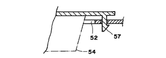
図14および図15は第2実施例であり、52はラジオ取付口、53はパネル取付口である。また、一方のダクト45はエアコン47の吹出口で他方は吸引(排出)口である。図16はラジオ54を螺子55により取付けたものであり、図17はラジオ54に係合爪57を有する取付部材を取付け、取付け作業を容易にしたものである。
図17は、リアフレーム42の一例を示す斜視図であり、下部にエアコン47を収納固定し、中間部の左右側に前記送風口48を設けた筒部材58を設ける。
【0011】
しかして、キャビン1内のステップ5は上下動自在に設ける。ステップ5には前側操作パネル6を固定し、前側操作パネル6には上下動自在の上下動杆59を設け、上下動杆59の上部は上下操作レバー60を設け、上下動杆59の下部はガスダンパー61のロックレバー62に接続する。63は機体側と前側操作パネル6との間に設けた案内ガイド、64はステップ5の周囲に設けた案内体である。また、前記座席8は、ガスダンパー65により取付けるが、座席8の下部には座席支持フレーム66を設け、座席支持フレーム66の後端には案内溝67を形成し、案内溝67にエンジンカバー69側に設けたスライド案内レール70を係合させる。なお、前記座席8は軸71に前側回動可能であり、メンテナンスを行う。
【0012】
次に実施例の作用を述べる。
本発明は前記構成であり、キャビン1は、略四角形状の中央空間部23と、該中央空間部23の上方の一方側中央凹部24と、一方側中央凹部24の両側の一方側起立部25と一方側起立部25の側部の側方に突き出る側方突出部26との間にそれぞれ形成した一方側角空間部27と、中央空間部23の下方に形成した他方側中央凹部28と、他方側中央凹部28の両側に形成した他方側起立部29と側方突出部26との間にそれぞれ形成した他方側角空間部30とからなるフレーム部材22によりキャビンフレーム15を形成したから、キャビンフレーム15を構成するフレーム部材22の各部に嵌合部材32や取付部材37を取付けることで、ルーフ33や側部フレーム35やドアウインド13やリアフレーム42等のあらゆるものをキャビンフレーム15に取付けられ、キャビン1の製造、組立が容易となり、外部との遮断性および遮音性に優れたキャビン1にでき、エアコン47も効率よく作動させることが可能になる。
【0013】
特に、フレーム部材22を使用して前側縦骨格フレーム16等からなるキャビンフレーム15を構成しているから、同一形状なのでコストを低くでき、加工が容易であり、また、合成樹脂を成形したものなので品質精度も高くする。
また、フレーム部材22は、略四角形状の中央空間部23と、該中央空間部23の上方の一方側中央凹部24と、一方側中央凹部24の両側の一方側起立部25と一方側起立部25の側部の側方に突き出る側方突出部26との間にそれぞれ形成した一方側角空間部27と、中央空間部23の下方に形成した他方側中央凹部28と、他方側中央凹部28の両側に形成した他方側起立部29と側方突出部26との間にそれぞれ形成した他方側角空間部30とにより形成しているから、あらゆる向きに使用しても、強度を確保でき、また、フレーム部材22のあらゆる部分が嵌合部材32や取付部材37を取付けるのに合理的に使用でき、キャビン1の設計の自由度を高める。
【0014】
しかして、前記キャビン1のキャビンフレーム15に取付けるルーフ33は、合成樹脂により左右両側に空間部44を形成し、空間部44はダクト45によりキャビン1内に連通し、一方のダクト45に後側に設けた接続口46にエアコン47の送風口48を接続し、ルーフ33の上部内側にはレザー等の任意の内張りをした内装材49を嵌合させ、また、ルーフ33の前側にはスピーカー等の取付口51を設けているから、外部との遮断性および遮音性に優れたルーフ33とし、一体成形で取付口51やダクト45を形成するので製造および組立が容易であり、キャビン1の上部を所謂コックピット感覚に形成して商品価値および作業性を高め、また、キャビン1のコスト軽減、軽量化、組立の容易化に貢献する。
しかして、キャビンフレーム15に取付けるリアフレーム42は、下部にエアコン47を収納固定し、中間部の左右側に送風口48を設けた筒部材58を設けているから、リアフレーム42をユニット化し、組立を容易にする。
しかして、キャビン1内のステップ5は、上下操作レバー60を上方に引くと、ガスダンパー61のロックレバー62がガスダンパー61内のエアー室を連通させてエアーを流してロックを解除し、上下操作レバー60によりステップ5を上動させる力を補助して、軽くステップ5を上動させ、ステップ5の高さ調節を行って、作業者の操作性を向上させる。反対に、上下操作レバー60を下方に押すと、ガスダンパー61のロックレバー62がロックを解除し、作業者の体重および下方に押す力により取付フレーム3を下動させる。
【0015】
この場合、機体側と前側操作パネル6との間に案内ガイド63を、ステップ5の周囲には案内体64をそれぞれ設けているから、円滑かつ確実に上下する。
また、座席8は、ガスダンパー65により上下自在に取付け、座席8の下部には後端に案内溝67を形成した座席支持フレーム66を設け、案内溝67にエンジンカバー69側に設けたスライド案内レール70を係合させているから、座席8を確実に上下させるだけでなく、エンジンカバー69および座席8を容易に移動させることができ、メンテナンスを容易に行える。
【0016】
【効果】
本発明は、機体フレーム2の上方に取付フレーム3を設け、該取付フレーム3には下部フレーム4を取付け、該下部フレーム4は、下部に作業者の立つステップ5を、該ステップ5の前側には前側操作パネル6を夫々設け、ステップ5の左右いずれか一側は解放し他側には側部操作パネル7を設け、前記ステップ5の後側には座席8を取付ける座席取付部9に形成して構成し、前記下部フレーム4にはステップ5および座席8の周囲をルーフ33あるいは側部フレーム35あるいはフロントウインド38あるいはリアウインド43により包囲するように形成したキャビン1のキャビンフレーム15を取付け、該キャビンフレーム15は、少なくとも、左右一対の前側縦骨格フレーム16と、前側縦骨格フレーム16に続く左右上部骨格フレーム17と、左右上部骨格フレーム17に続く後側縦骨格フレーム18を有して構成し、前記キャビンフレーム15は、略四角形状の中央空間部23と、該中央空間部23の上方の一方側中央凹部24と、一方側中央凹部24の両側の一方側起立部25と一方側起立部25の側部の側方に突き出る側方突出部26との間にそれぞれ形成した一方側角空間部27と、中央空間部23の下方に形成した他方側中央凹部28と、他方側中央凹部28の両側に形成した他方側起立部29と側方突出部26との間にそれぞれ形成した他方側角空間部30とにより、前記中央空間部23の断面四角形の四面の全てに一方側起立部25または側方突出部26または他方側起立部29を形成して断面形状が略同一なフレーム部材22により形成し、該フレーム部材22の各部に嵌合部材32や取付部材37を介して前記ルーフ33等を取付て構成した作業機の運転部構造としたものであるから、同一形状のフレーム部材22を使用して前側縦骨格フレーム16等からなるキャビンフレーム15を構成しているので、製造コストを低くでき、加工が容易であり、また、同一形状に成形するので品質精度も高くできる。
また、キャビンフレーム15を構成するフレーム部材22の各部に嵌合部材32や取付部材37を取付けることで、ルーフ33等のあらゆるものをキャビンフレーム15に取付けられ、キャビン1の製造、組立が容易となる。特に、ボルト等を使用しないので、組立が容易にでき、また、シール部材40の取付も容易になって外部との遮断性および遮音性に優れたキャビン1にでき、作業環境を良好にする。
また、フレーム部材22は、略四角形状の中央空間部23と、該中央空間部23の上方の一方側中央凹部24と、一方側中央凹部24の両側の一方側起立部25と一方側起立部25の側部の側方に突き出る側方突出部26との間にそれぞれ形成した一方側角空間部27と、中央空間部23の下方に形成した他方側中央凹部28と、他方側中央凹部28の両側に形成した他方側起立部29と側方突出部26との間にそれぞれ形成した他方側角空間部30とにより、前記中央空間部23の断面四角形の四面の全てに一方側起立部25または側方突出部26または他方側起立部29を夫々形成しているから、あらゆる向きに使用しても、強度を確保でき、また、フレーム部材22のあらゆる部分が嵌合部材32や取付部材37を取付けるのに合理的に使用でき、キャビン1の設計の自由度を高める。
【図面の簡単な説明】
【図1】 キャビンの斜視図。
【図2】 分解状態の斜視図。
【図3】 キャビンの側面図と一部正面図。
【図4】 フレーム部材の断面図。
【図5】 A−A断面図。
【図6】 B−B断面図。
【図7】 C−C断面図。
【図8】 D−D断面図。
【図9】 D−D断面図の第2実施例図。
【図10】 E−E断面図。
【図11】 ルーフの底面図。
【図12】 同断面図。
【図13】 同断面図。
【図14】 同第2実施例底面図。
【図15】 同断面図。
【図16】 ラジオ取付状態断面図。
【図17】 同第2実施例図。
【図18】 リアフレームの斜視図。
【図19】 ステップの高さ調節装置の縦断側面図。
【図20】 同一部平面図。
【図21】 座席支持フレームの平面図。
【図22】 座席高さ調節装置の縦断側面図。
【符号の説明】
1…キャビン、2…機体フレーム、3…取付フレーム、4…下部フレーム、5…ステップ、6…前側操作パネル、7…側部操作パネル、8…座席、9…座席取付部、10…ドア、11…ハンドル、12…ドア取付金具、13…ドアウインド、14…ドア下部ウインド、15…キャビンフレーム、16…前側縦骨格フレーム、17…左右上部骨格フレーム、18…後側縦骨格フレーム、19…上部横骨格フレーム、20…後側上部横骨格フレーム、21…後側下部横骨格フレーム、22…フレーム部材、23…中央空間部、24…一方側中央凹部、25…一方側起立部、26…側方突出部、27…一方側角空間部、28…他方側中央凹部、29…他方側起立部、30…他方側角空間部、32…嵌合部材、33…ルーフ、34…ルーフインナー、35…側部フレーム、36…サッシ、37…取付部材、38…フロントウインド、39…フラッシモール、40…シール部材、42…リアフレーム、43…リアウインド、44…空間部、45…ダクト、46…接続口、47…エアコン47、48…送風口、49…内装材、50…補強リブ、51…取付口、52…ラジオ取付口、53…パネル取付口、54…ラジオ、55…螺子、57…係合爪、58…筒部材、59…上ル動杆、60…上下操作レバー、61…ガスダンパー、62…ロックレバー、63…案内ガイド、64…案内体、65…ガスダンパー、66…座席支持フレーム、67…案内溝、69…エンジンカバー、70…スライド案内レール、71…軸。
[0001]
[Industrial application fields]
The present invention relates to an operating unit structure of a work machine.
[0002]
[Prior art]
JP-A-2-23810 discloses a cabin in which a step and a seat are provided above a body frame, and the step and the seat are surrounded by a roof, a front window, or a rear window. Describes a configuration in which a cabin frame is formed by a front vertical frame, a left and right upper frame, or a rear vertical frame, and the roof or the like is attached to the cabin frame with screws or bolts.
[0003]
[Problems to be solved by the invention]
In the known example, each part of the cabin frame is formed in a different shape. Therefore, when synthetic resin is used, there is a problem that the cost of the mold is considerably high and the cost is high.
In addition, there is no ingenuity in the shape of each part of the cabin frame, and it is simply made of synthetic resin in accordance with the shape of the cabin frame formed of conventional steel, so screws and bolts are used to attach the roof etc. to the cabin frame There is also a problem that installation is troublesome.
[0004]
OBJECT OF THE INVENTION
Reduce costs, eliminate the need for screws and bolts, and facilitate assembly.
[0005]
[Means for Solving the Problems]
In the present invention, a mounting frame 3 is provided above the body frame 2, a lower frame 4 is mounted on the mounting frame 3, and the lower frame 4 has a step 5 where an operator stands at the lower side, and a front side of the step 5. Is provided with a front operation panel 6, one of the left and right sides of step 5 is released, a side operation panel 7 is provided on the other side, and a seat mounting portion 9 for attaching a seat 8 is formed on the rear side of step 5. The cabin frame 15 of the cabin 1 formed so as to surround the step 5 and the seat 8 with the roof 33, the side frame 35, the front window 38, or the rear window 43 is attached to the lower frame 4 . The cabin frame 15 includes at least a pair of left and right front vertical frame frames 16 and left and right upper frame frames following the front vertical frame frame 16. And 17 constitute a side vertical skeletal frame 18 after following the right and left upper skeleton frame 17, the cabin frame 15 includes a substantially rectangular central space portion 23, one side central above the central space portion 23 A one-sided angular space 27 formed between the concave portion 24 and the one-side standing portion 25 on both sides of the one-side central concave portion 24 and the side protruding portion 26 protruding to the side of the side portion of the one-side standing portion 25; The other-side central concave portion 28 formed below the central space portion 23, and the other-side angular space portion formed between the other-side standing portion 29 and the side protruding portion 26 formed on both sides of the other-side central concave portion 28, respectively. 30 , one side standing part 25 or side protruding part 26 or the other side standing part 29 is formed on all four sides of the square section of the central space 23 to form the frame member 22 having substantially the same cross-sectional shape. , The frame part 22 each part of it through the fitting member 32 and the mounting member 37 that is a driving unit structure of the working machine configured have been installed to the roof 33 and the like.
[0006]
【Example】
An embodiment of the present invention will be described with reference to the drawings. Reference numeral 1 denotes a cabin 1 of a working machine such as a combine. A mounting frame 3 for mounting a seat or the like is provided above the body frame 2. An engine may be provided in the mounting frame 3. The lower frame 4 is attached to the mounting frame 3 (FIG. 2). The lower frame 4 is provided with a step 5 where an operator stands at the lower part, a front operation panel 6 is provided on the front side of the step 5, one of the left and right sides of the step 5 is released, and the side operation panel 7 is provided on the other side. In the rear side of step 5, a seat mounting portion 9 for mounting a seat 8 to be described later is formed. Reference numeral 10 denotes a door, 11 denotes a handle, 12 denotes a door mounting bracket, 13 denotes a door window, and 14 denotes a door lower window.
A cabin frame 15 that surrounds the seat 8 is attached to the lower frame 4. The cabin frame 15 includes a pair of left and right front skeleton frames 16, a left and right upper skeleton frame 17 that follows the front vertical skeleton frame 16, a rear vertical skeleton frame 18 that follows the left and right upper skeleton frame 17, and the like. That is, the cabin frame 15 only needs to surround the seat 8, the front operation panel 6 and the like, and the shape thereof is arbitrary, and the cabin frame 15 is configured by the frame group as described above. In the embodiment, reinforcing frames for the front upper horizontal frame 19, the rear upper horizontal frame 20, and the rear lower horizontal frame 21 are provided, but the presence of these is not a requirement.
[0007]
Thus, the cabin frame 15 is composed of the same frame member 22. This is the gist of the present invention. The frame member 22 is made of synthetic resin, and its cross-sectional shape will be described with reference to the direction in FIG. 4 for convenience. A substantially square central space portion 23 is formed in the center, and one side is formed above the central space portion 23. The side center recess 24 is formed, the one side standing part 25 is formed on both sides of the one side center recess 24, and the side protrusion 26 protruding sideways is formed on the side of the one side standing part 25. One side angular space portion 27 is formed between the protruding portion 26 and the one side standing portion 25, respectively. Reference numeral 28 denotes the other side central concave portion 28 formed below the central space portion 23, the other side standing portion 29 is formed on both sides of the other side central concave portion 28, and between the other side standing portion 29 and the side protruding portion 26. Each of the other side corner spaces 30 is formed.
FIG. 5 is an example used for the inner left and right upper skeleton frame 17 of the cabin frame 15. A fitting member 32 having a fitting groove is fitted in the central recess 24 on one side of the frame member 22. The side portion of the roof 33 is fitted into the fitting groove of the joint member 32. Further, the end portion of the roof inner 34 is fitted to the side protruding portion 26 of the frame member 22. Reference numeral 35 denotes a side frame of the cabin 1, and an upper portion of the side frame 35 is attached to a side surface of the other side standing portion 29 of the frame member 22, a sash 36 is attached to the side frame 35, and a door window 13 of the sash 36 is attached. Install.
[0008]
FIG. 6 shows an example of use of the front vertical skeleton frame 16. The mounting member 37 is positioned in the one side corner space 27 of the frame member 22, and the mounting member 37 is fixed to the side protrusion 26. The side edge of the front window 38 is fixed. 39 is a flash mol. A seal member 40 with which the door 10 abuts is attached to the other-side corner space 30 of the frame member 22, and the seal member 40 is also fitted into the other-side central recess 28. 41 is a dam.
FIG. 7 shows an example of use of the rear vertical skeleton frame 18, the fitting member 32 is fitted into the one-side central recess 24, the rear frame 42 of the cabin 1 is fitted into the fitting member 32, and the frame member 22. The seal member 40 with which the door 10 abuts is attached to the other-side corner space 30, and the seal member 40 is also fitted into the other-side central recess 28.
FIG. 8 shows an example of use of the rear upper horizontal skeleton frame 20, in which a fitting member 32 is fitted into the central recess 24 on one side of the frame member 22, and the rear portion of the roof 33 is fitted into the fitting member 32. The end of the roof inner 34 is fitted to the side protrusion 26 of the frame member 22, and the attachment member 37 is fitted to the side protrusion 26 of the frame member 22 on the other rear side. A part of the member 37 is located in the other side angular space 30 and fixed to the side protrusion 26 and the other side standing part 29, and the front upper part of the rear frame 42 is fitted into the fitting groove of the mounting member 37. doing. 43 is a rear window.
[0009]
FIG. 9 shows a second embodiment of the rear upper horizontal skeleton frame 20, in which a mounting member 37 is positioned in one side angular space 27 of the frame member 22 facing upward, and the side protrusions 26 and one side are arranged. The rear end of the roof 33 is fitted and fixed to the mounting member 37, the fitting member 32 is fitted to the central recess 24 on one side of the frame member 22, and the rear frame 42 is fitted to the fitting member 32. The front upper end is fitted.
FIG. 10 shows an example of use of the upper horizontal skeleton frame 19. The mounting member 37 is positioned in the one side corner space portion 27 of the frame member 22 facing downward, and the mounting member 37 is fixed to the side protruding portion 26. The upper edge of the front window 38 is fixed to the member 37, and the flash molding 39 is fitted into the central recess 24 on one side. An attachment member 37 is positioned in the upper one side angular space 27, and a fitting groove of the attachment member 37 is fitted to the side protrusion 26 to adhere to the side protrusion 26 and the side of the one side upright 25. Then, the front end portion of the roof 33 is fitted into another fitting groove of the mounting member 37.
[0010]
FIG. 11 shows an example of the roof 33, which is made of synthetic resin, and has a space 44 formed on both the left and right sides. The space 44 communicates with the interior of the cabin 1 through a duct 45. A blower port 48 of an air conditioner 47 described later is connected to a connection port 46 provided on the rear side. An interior material 49 having an arbitrary lining such as leather is fitted and attached to the upper inner side of the roof 33. Reference numeral 50 denotes an integrally formed reinforcing rib, and 51 denotes a mounting opening for a speaker or the like provided on the front inner side of the roof 33.
14 and 15 show a second embodiment, 52 is a radio mounting opening, and 53 is a panel mounting opening. One duct 45 is an air outlet of the air conditioner 47 and the other is a suction (discharge) port. 16 shows the radio 54 attached with a screw 55, and FIG. 17 shows the radio 54 attached with an attachment member having an engaging claw 57 to facilitate the attachment work.
FIG. 17 is a perspective view showing an example of the rear frame 42, in which an air conditioner 47 is housed and fixed at the lower portion, and a cylindrical member 58 having the blower ports 48 is provided on the left and right sides of the intermediate portion.
[0011]
Therefore, the step 5 in the cabin 1 is provided to be movable up and down. In step 5, the front operation panel 6 is fixed, and the front operation panel 6 is provided with a vertically movable rod 59 that can be moved up and down. Connected to the lock lever 62 of the gas damper 61. 63 is a guide guide provided between the machine body side and the front operation panel 6, and 64 is a guide body provided around the step 5. The seat 8 is attached by a gas damper 65. A seat support frame 66 is provided below the seat 8, a guide groove 67 is formed at the rear end of the seat support frame 66, and an engine cover 69 is formed in the guide groove 67. The slide guide rail 70 provided on the side is engaged. The seat 8 is pivotable forward with respect to the shaft 71 and performs maintenance.
[0012]
Next, the operation of the embodiment will be described.
The present invention has the above-described configuration, and the cabin 1 includes a substantially rectangular central space portion 23, a one-side central recess 24 above the central space portion 23, and one-side standing portions 25 on both sides of the one-side center recess 24. And one side corner space portion 27 formed between the side protruding portion 26 protruding to the side of the side portion of the one side standing portion 25, and the other side center concave portion 28 formed below the center space portion 23, Since the cabin frame 15 is formed by the frame member 22 including the other-side standing space 29 formed on both sides of the other-side central recess 28 and the other-side angular space 30 formed between the side protrusions 26, the cabin By attaching the fitting member 32 and the attachment member 37 to each part of the frame member 22 constituting the frame 15, the roof 33, the side frame 35, the door window 13, the rear frame 42, etc. Attached to the bottle frame 15, manufacturing of the cabin 1, the assembly is facilitated, can be a cabin 1 which is excellent in barrier property and sound insulating property between the external, it is possible to air conditioning 47 also operates efficiently.
[0013]
In particular, since the cabin frame 15 composed of the front vertical frame 16 and the like is configured using the frame member 22, the shape is the same, so the cost can be reduced, processing is easy, and synthetic resin is molded. Increase quality accuracy.
The frame member 22 includes a substantially square central space portion 23, a one-side central concave portion 24 above the central space portion 23, one-side standing portions 25 and one-side standing portions on both sides of the one-side central concave portion 24. 25, one side corner space 27 formed between the side protrusions 26 protruding to the side of the side portion 25, the other side center recess 28 formed below the center space 23, and the other side center recess 28. Since it is formed by the other side standing space 29 and the other side angular space portion 30 formed between the side protruding portions 26, the strength can be secured even if used in any direction, In addition, every part of the frame member 22 can be reasonably used to attach the fitting member 32 and the attachment member 37, and the degree of freedom in designing the cabin 1 is increased.
[0014]
Thus, the roof 33 attached to the cabin frame 15 of the cabin 1 is formed with a space portion 44 on both the left and right sides of a synthetic resin. The space portion 44 communicates with the interior of the cabin 1 through a duct 45 and is connected to one duct 45 on the rear side. A blower port 48 of an air conditioner 47 is connected to the connection port 46 provided in the interior, an interior material 49 with an arbitrary lining such as leather is fitted inside the upper portion of the roof 33, and a speaker or the like is disposed on the front side of the roof 33. Since the mounting opening 51 and the duct 45 are formed by integral molding, the mounting opening 51 and the duct 45 are formed by integral molding, so that the manufacturing and assembly are easy, and the upper portion of the cabin 1 is provided. Is formed into a so-called cockpit sensation to enhance the value of the product and workability, and contribute to reducing the cost, weight and facilitating assembly of the cabin 1.
The rear frame 42 attached to the cabin frame 15 accommodates and fixes the air conditioner 47 in the lower part and is provided with the cylindrical member 58 provided with the air outlets 48 on the left and right sides of the intermediate part. Facilitates assembly.
Thus, in step 5 in the cabin 1, when the up / down operation lever 60 is pulled upward, the lock lever 62 of the gas damper 61 communicates the air chamber in the gas damper 61 to flow air to release the lock, The operation lever 60 assists the force for moving the step 5 upward, and the step 5 is moved lightly, and the height of the step 5 is adjusted to improve the operability for the operator. On the contrary, when the up / down operation lever 60 is pushed downward, the lock lever 62 of the gas damper 61 releases the lock, and the attachment frame 3 is moved downward by the weight of the operator and the downward pushing force.
[0015]
In this case, the guide guide 63 is provided between the machine body side and the front operation panel 6, and the guide body 64 is provided around the step 5.
The seat 8 is mounted up and down by a gas damper 65. A seat support frame 66 having a guide groove 67 formed at the rear end is provided at the lower portion of the seat 8, and a slide guide provided on the guide groove 67 on the engine cover 69 side. Since the rail 70 is engaged, not only can the seat 8 be moved up and down reliably, but also the engine cover 69 and the seat 8 can be easily moved, and maintenance can be performed easily.
[0016]
【effect】
In the present invention, a mounting frame 3 is provided above the body frame 2, a lower frame 4 is mounted on the mounting frame 3, and the lower frame 4 has a step 5 where an operator stands at the lower side, and a front side of the step 5. Is provided with a front operation panel 6, one of the left and right sides of step 5 is released, a side operation panel 7 is provided on the other side, and a seat mounting portion 9 for attaching a seat 8 is formed on the rear side of step 5. The cabin frame 15 of the cabin 1 formed so as to surround the step 5 and the seat 8 with the roof 33, the side frame 35, the front window 38, or the rear window 43 is attached to the lower frame 4 . The cabin frame 15 includes at least a pair of left and right front vertical frame frames 16 and left and right upper frame frames following the front vertical frame frame 16. And 17 constitute a side vertical skeletal frame 18 after following the right and left upper skeleton frame 17, the cabin frame 15 includes a substantially rectangular central space portion 23, one side central above the central space portion 23 A one-sided angular space 27 formed between the recess 24 and the one-side standing portion 25 on both sides of the one-side central recess 24 and the side protruding portion 26 protruding to the side of the side portion of the one-side standing portion 25; The other-side central concave portion 28 formed below the central space portion 23, and the other-side angular space portion formed between the other-side standing portion 29 and the side protruding portion 26 formed on both sides of the other-side central concave portion 28, respectively. 30 , one side standing part 25 or side protruding part 26 or the other side standing part 29 is formed on all four sides of the square section of the central space 23 to form the frame member 22 having substantially the same cross-sectional shape. , The frame part Since the operating part structure of the work machine is configured by attaching the roof 33 and the like to each part 22 via the fitting member 32 and the attachment member 37, the front vertical frame is formed using the frame member 22 having the same shape. Since the cabin frame 15 including the frame 16 and the like is configured, the manufacturing cost can be reduced, the processing can be easily performed, and the quality accuracy can be increased because the same shape is formed.
Further, by attaching the fitting member 32 and the attachment member 37 to each part of the frame member 22 constituting the cabin frame 15, it is possible to attach everything such as the roof 33 to the cabin frame 15, making it easy to manufacture and assemble the cabin 1. Become. In particular, since no bolts or the like are used, the assembly can be facilitated, and the sealing member 40 can be easily attached, so that the cabin 1 can be made excellent in the insulation and sound insulation from the outside, and the working environment is improved.
The frame member 22 includes a substantially square central space portion 23, a one-side central concave portion 24 above the central space portion 23, one-side standing portions 25 and one-side standing portions on both sides of the one-side central concave portion 24. 25, one side corner space 27 formed between the side protrusions 26 protruding to the side of the side portion 25, the other side center recess 28 formed below the center space 23, and the other side center recess 28. The other side upright portions 29 formed on both sides and the other side angular space portions 30 formed between the side protruding portions 26 respectively, and the one side upright portions 25 on all four sides of the square section of the central space portion 23. Alternatively, since the side protruding portion 26 or the other side standing portion 29 is formed, the strength can be ensured even when used in any direction, and any part of the frame member 22 can be fitted to the fitting member 32 or the mounting member 37. Reasonable to install Can be used, enhance the degree of freedom in the design of the cabin 1.
[Brief description of the drawings]
FIG. 1 is a perspective view of a cabin.
FIG. 2 is an exploded perspective view.
FIG. 3 is a side view and a partial front view of the cabin.
FIG. 4 is a cross-sectional view of a frame member.
FIG. 5 is a cross-sectional view taken along the line AA.
FIG. 6 is a sectional view taken along line BB.
FIG. 7 is a sectional view taken along the line CC.
FIG. 8 is a DD cross-sectional view.
FIG. 9 is a second embodiment of the DD cross-sectional view.
FIG. 10 is an EE cross-sectional view.
FIG. 11 is a bottom view of the roof.
FIG. 12 is a sectional view of the same.
FIG. 13 is a sectional view of the same.
FIG. 14 is a bottom view of the second embodiment.
FIG. 15 is a sectional view of the same.
FIG. 16 is a cross-sectional view of a radio mounting state.
FIG. 17 is a diagram of the second embodiment.
FIG. 18 is a perspective view of a rear frame.
FIG. 19 is a vertical side view of the step height adjusting device.
FIG. 20 is a plan view of the same part.
FIG. 21 is a plan view of a seat support frame.
FIG. 22 is a longitudinal side view of the seat height adjusting device.
[Explanation of symbols]
DESCRIPTION OF SYMBOLS 1 ... Cabin, 2 ... Airframe frame, 3 ... Mounting frame, 4 ... Lower frame, 5 ... Step, 6 ... Front side operation panel, 7 ... Side part operation panel, 8 ... Seat, 9 ... Seat attachment part, 10 ... Door, DESCRIPTION OF SYMBOLS 11 ... Handle, 12 ... Door mounting bracket, 13 ... Door window, 14 ... Door lower window, 15 ... Cabin frame, 16 ... Front vertical frame, 17 ... Left and right upper frame, 18 ... Rear vertical frame, 19 ... Upper horizontal skeleton frame, 20 ... rear upper horizontal skeleton frame, 21 ... rear lower horizontal skeleton frame, 22 ... frame member, 23 ... central space part, 24 ... one side central recess, 25 ... one side standing part, 26 ... Side projection, 27 ... One side angular space, 28 ... Other side central recess, 29 ... Other side standing part, 30 ... Other side angular space, 32 ... Fitting member, 33 ... Roof, 34 ... Roof inner, 5 ... side frame, 36 ... sash, 37 ... mounting member, 38 ... front window, 39 ... flash molding, 40 ... seal member, 42 ... rear frame, 43 ... rear window, 44 ... space, 45 ... duct, 46 Connection port 47 Air conditioner 47 48 Air blower 49 Interior material 50 Reinforcing rib 51 Mounting port 52 Radio mounting port 53 Panel mounting port 54 Radio 55 Screw 57 ... engaging claws, 58 ... cylindrical member, 59 ... upper sliding lever, 60 ... vertical operation lever, 61 ... gas damper, 62 ... lock lever, 63 ... guide guide, 64 ... guide body, 65 ... gas damper, 66 ... seat Support frame, 67 ... guide groove, 69 ... engine cover, 70 ... slide guide rail, 71 ... shaft.

Claims (1)

機体フレーム2の上方に取付フレーム3を設け、該取付フレーム3には下部フレーム4を取付け、該下部フレーム4は、下部に作業者の立つステップ5を、該ステップ5の前側には前側操作パネル6を夫々設け、ステップ5の左右いずれか一側は解放し他側には側部操作パネル7を設け、前記ステップ5の後側には座席8を取付ける座席取付部9に形成して構成し、前記下部フレーム4にはステップ5および座席8の周囲をルーフ33あるいは側部フレーム35あるいはフロントウインド38あるいはリアウインド43により包囲するように形成したキャビン1のキャビンフレーム15を取付け、該キャビンフレーム15は、少なくとも、左右一対の前側縦骨格フレーム16と、前側縦骨格フレーム16に続く左右上部骨格フレーム17と、左右上部骨格フレーム17に続く後側縦骨格フレーム18を有して構成し、前記キャビンフレーム15は、略四角形状の中央空間部23と、該中央空間部23の上方の一方側中央凹部24と、一方側中央凹部24の両側の一方側起立部25と一方側起立部25の側部の側方に突き出る側方突出部26との間にそれぞれ形成した一方側角空間部27と、中央空間部23の下方に形成した他方側中央凹部28と、他方側中央凹部28の両側に形成した他方側起立部29と側方突出部26との間にそれぞれ形成した他方側角空間部30とにより、前記中央空間部23の断面四角形の四面の全てに一方側起立部25または側方突出部26または他方側起立部29を形成して断面形状が略同一なフレーム部材22により形成し、該フレーム部材22の各部に嵌合部材32や取付部材37を介して前記ルーフ33等を取付て構成した作業機の運転部構造。A mounting frame 3 is provided above the body frame 2, a lower frame 4 is mounted on the mounting frame 3, and the lower frame 4 has a step 5 where an operator stands at the lower part, and a front operation panel on the front side of the step 5. 6 is provided, one of the left and right sides of Step 5 is released, the side operation panel 7 is provided on the other side, and the seat mounting portion 9 for attaching the seat 8 is formed on the rear side of Step 5. The cabin frame 15 of the cabin 1 formed so as to surround the step 5 and the seat 8 with the roof 33, the side frame 35, the front window 38, or the rear window 43 is attached to the lower frame 4. Are at least a pair of left and right front vertical skeleton frames 16, and a left and right upper skeleton frame 17 following the front vertical skeleton frame 16, Constitute a side vertical skeletal frame 18 after following the right upper skeleton frame 17, the cabin frame 15 includes a substantially rectangular central space portion 23, and the one side central recess 24 of the upper of the central space portion 23 The one-side angular space 27 formed between the one-side standing portion 25 on both sides of the one-side central recess 24 and the side protrusions 26 projecting to the side of the side portion of the one-side standing portion 25, and the central space the other side central recess 28 formed in the lower parts 23, by the other side angle space 30 formed respectively between the other side upright portion 29 and the side projecting portion 26 formed on both sides of the other side central recess 28 The one side standing part 25 or the side protruding part 26 or the other side standing part 29 is formed on all four faces of the central space part 23 in the quadrangular section, and is formed by the frame member 22 having substantially the same sectional shape. Each of the members 22 Operation part structure of the working machine configured have been installed to the roof 33 or the like through the fitting member 32 and the mounting member 37.
JP11634995A 1995-04-18 1995-04-18 Operating unit structure of work equipment Expired - Fee Related JP3663665B2 (en)

Priority Applications (1)

Application Number Priority Date Filing Date Title
JP11634995A JP3663665B2 (en) 1995-04-18 1995-04-18 Operating unit structure of work equipment

Applications Claiming Priority (1)

Application Number Priority Date Filing Date Title
JP11634995A JP3663665B2 (en) 1995-04-18 1995-04-18 Operating unit structure of work equipment

Publications (2)

Publication Number Publication Date
JPH08289653A JPH08289653A (en) 1996-11-05
JP3663665B2 true JP3663665B2 (en) 2005-06-22

Family

ID=14684760

Family Applications (1)

Application Number Title Priority Date Filing Date
JP11634995A Expired - Fee Related JP3663665B2 (en) 1995-04-18 1995-04-18 Operating unit structure of work equipment

Country Status (1)

Country Link
JP (1) JP3663665B2 (en)

Also Published As

Publication number Publication date
JPH08289653A (en) 1996-11-05

Similar Documents

Publication Publication Date Title
US5005898A (en) Vehicle structure and the method for its assembly
US7401835B2 (en) Integrated center stack for a motor vehicle
US9359016B2 (en) Cabin for work vehicles
US6273127B1 (en) Pressure relief valve assembly
JP2007062573A (en) Air conditioning structure for cabin of working vehicle
JP2003146052A (en) Cabin structure
JPH01240382A (en) Front body construction for vehicle
JP3663665B2 (en) Operating unit structure of work equipment
JPH01208247A (en) Cabin of power vehicle
JP2005001537A (en) Air-conditioning structure for cabin of working vehicle
JPH0761764B2 (en) Cabin structure of tractor
CA2297697C (en) Door trim panel with integrated defrost duct and substructure
JPH0861690A (en) Decoration panel for air conditioner
JP2002068026A (en) Cabin for tractor
JP4121422B2 (en) Air conditioning structure for cabin of work vehicle
US3877355A (en) Automotive air conditioner assembly
JPH08192620A (en) Cabin of tractor or the like
JP2012201271A (en) Working vehicle
JP2001088544A (en) Air blowoff structure of instrument panel
JP2009255919A (en) Air-conditioning structure for cabin of work vehicle
JPH06166381A (en) Vehicle body front structure of automobile
JPH0352613Y2 (en)
JP3903984B2 (en) Tractor air conditioner mounting device
JP4066757B2 (en) Air conditioner for vehicles
JP3686798B2 (en) Cabin air conditioner mounting structure

Legal Events

Date Code Title Description
A977 Report on retrieval

Free format text: JAPANESE INTERMEDIATE CODE: A971007

Effective date: 20040402

A131 Notification of reasons for refusal

Free format text: JAPANESE INTERMEDIATE CODE: A131

Effective date: 20040914

A521 Written amendment

Free format text: JAPANESE INTERMEDIATE CODE: A523

Effective date: 20041111

TRDD Decision of grant or rejection written
A01 Written decision to grant a patent or to grant a registration (utility model)

Free format text: JAPANESE INTERMEDIATE CODE: A01

Effective date: 20050308

A61 First payment of annual fees (during grant procedure)

Free format text: JAPANESE INTERMEDIATE CODE: A61

Effective date: 20050321

R150 Certificate of patent or registration of utility model

Free format text: JAPANESE INTERMEDIATE CODE: R150

FPAY Renewal fee payment (event date is renewal date of database)

Free format text: PAYMENT UNTIL: 20080408

Year of fee payment: 3

FPAY Renewal fee payment (event date is renewal date of database)

Free format text: PAYMENT UNTIL: 20110408

Year of fee payment: 6

LAPS Cancellation because of no payment of annual fees