【0001】
【発明の属する技術分野】
本発明は、ガードレール等の相手物に固定されて自動車等からの投光による光を反射して相手物の存在を知らせる反射部品に関する。
【0002】
【従来の技術】
【特許文献】
特開2002−88723号
従来、道路に沿ってガードレールが設置され、通行する自動車の安全が図られているが、夜間自動車の運転者ができるだけ早く道路の曲がる方向が分かるようにガードレール側面に取り付ける半円筒面形状の反射面を持つ反射キャップが創案されている。
【0003】
【発明が解決しようとする課題】
この反射キャップの場合には、道路が直線状であっても、半円筒面形状の端部側に自動車からの光が当たるので、遠くに位置する自動車の運転手もガードレールの位置を早い時期に把握することができる。しかしながら、道路が大きく曲がっている場合には、光は半円筒面部の前面部に当たり、一定幅の反射面を得ることができるが、その端部側に十分な側面があるにも拘わらずほとんど光が当たらず、反射キャップの大きさの割に反射面が大して増加しない等の欠点が生じている。
【0004】
本発明は、上記欠点の除去を目的とするもので、ガードレール等の相手物に取付けられて遠方からの光量の少ない光でも十分に反射することができ、しかも大きく曲がったところに設置されていてもどの角度からもその大きさに応じた反射面が無駄なく得られる反射部品を提供しようとするものである。
【0005】
【課題を解決するための手段】
反射部品は透過性のある材料でなり、その前面側または背面側の少なくとも一方側に短軸の長さを半径の1/3〜2/3とする円弧を水平断面上に持つ部分円筒面部が設けられ、この部分円筒面部の一つにビーズを有する反射層が設けられている。また、前記反射層の背面に金属を蒸着し、ビーズに再帰反射機能を持たせるようにしてもよい。
【0006】
前記部分円筒面部の前面側に酸化チタンをコーティングし、紫外線を受けることにより機能する光触媒機能により前面の汚れを分解するようにしたり、シリカをコーティングして親水機能を持たせて、汚れが流れ落ちるようにしてもよい。また、前記部分円筒面部の周縁部に相手物に固定される固定具に係合する係合溝を設けてもよい。さらに、前記固定具に後退可能な係止爪を設ける一方、部分円筒面部の周縁部の側方に有底の小孔を設けて、係止爪を小孔に対応して位置させるようにしてもよい。
【0007】
【発明の実施の形態】
以下、図面に基づき本発明の実施態様を反射部品の一例の反射キャップについて説明する。図1および図2において、1は相手物の一例のガードレール2に付設される反射キャップであり、透過性が高い無色の硬質樹脂でなっている。また、この反射キャップ1は前面側に位置して所定厚みを備えた部分円筒面部1aとその側部を覆って背面側に矩形状の周縁部を形成する壁面部1bとこれらにより形成される収納室1cとから構成されており、部分円筒面部1aを通過する光は大部分収納室1cに達するように構成されている。前記部分円筒面部1aは垂直断面が直線に、水平断面が円弧をなすように構成されており、その収納室1c側に円弧面1dが形成されるように構成されている。前記円弧は図3に示すように、その高さHを半径Rのほぼ1/2、すなわち長軸L、短軸(高さ)Hとすると、次式の
L=2(2RH−H2)1/2
から、長軸Lの長さが短軸(高さ)Hの長さのほぼ3.5倍となるように構成されている。この寸法関係から部分円筒面部1aのガードレール2からの飛び出し量すなわち高さHを極力抑え、なおかつ反射面はその3.5倍得られ、最適なバランスが得られる。また、この部分円筒面部1aの前面側には透過性が高く親水機能を持つ酸化チタン(図示せず)が塗布されており、自動車の排ガスの粒子等の汚れが付着しても紫外線を受けることにより機能する光触媒機能により汚れが分解され、雨水により簡単に洗い落とされるように構成されている。
【0008】
前記部分円筒面部1aの円弧面1dには、反射層3が形成されており、この反射層3は図6に示すように透過性の高いクリア樹脂層3aに固定された細かな多数のガラス製のビーズ3bと、このビーズ3bの背面を覆うように蒸着された金属蒸着層3cと、クリア樹脂層3aの前面に設けられた透過性の高いオレンジ色の着色樹脂層3dとからなっている。前記金属蒸着層3cは反射効率の高い金属が使用された蒸着層であればよく、アルミ蒸着層がコスト的にも最適である。また、前記ビーズ3bは図7に示すように背面に反射面を持つため、入射した光がこれと平行に抜け出る再帰反射機能を有し、わずかな光量の光でも投光側に大部分戻るように構成されている。さらに、前記着色樹脂層3dは光が通過するとオレンジ色を発し、ガードレール2の位置を運転者に知らせるように構成されている。なお、前記着色樹脂層3dはオレンジ色以外の危険を知らせる色であってもよい。また、着色樹脂層3dをクリア樹脂層3aとするとともに、反射キャップ1を着色した樹脂で構成してもよい。
【0009】
前記部分円筒面部1aの壁面部1bにはそれぞれ所定長さの係合溝1eが設けられており、後記する固定具4の係止板部4aが挿入可能に構成されている。また、前記壁面部1bの外側面にはそれぞれ両側の2カ所に有底の小孔1fが設けられており、対向する位置にある小孔1fを特殊工具(図示せず)で挟圧するとこの小孔1fが内部の係合溝1eに連通するように構成されている。
【0010】
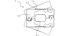
前記反射キャップ1はガードレール2を支柱(図示せず)に固定するボルト5の首下に取付けられる固定具4に装着される。この固定具4は、図4および図5に示すように1点が軸支された開閉自在な2枚の底板部4bと、この底板部4bそれぞれの一部を折り曲げた係止板部4aとからなっている。前記底板部4bの開放端側には閉止時嵌合する凹部(図示せず)と凸部(図示せず)とが設けられており、底板部4bは一旦閉止されると開放しにくくなるように構成されている。また、前記底板部4bの中央部内側にはそれぞれ切欠4cが設けられており、底板部4bの閉止時にはボルト5の首下の非円形段部5aに嵌合可能に構成されている。この非円形段部5aは円柱を2面取りした形状をしており、ガードレール2に設けられた廻り止め用の同形状のボルト取付穴2aに嵌合すると、固定具4の切欠4cをこの2面に沿わせ、係止板部4aをガードレール2に対して常に平行として、反射キャップ1を自動的にガードレール2と平行に取付け、常に反射状態が一定に保てるように構成されている。
【0011】
前記係止板部4aは底板部4b閉止時反射キャップ1の壁面部1bに設けられた係合溝1eに対応する位置となるように設けられており、反射キャップ1の部分円筒面部1aの延びる方向がガードレール2の延びる方向に簡単に一致するように構成されている。また、この係止板部4aは前記小孔1fに対応する位置に後退可能な係止爪4dを有しており、一旦係止板部4aが係合溝1eに挿入されると、引き抜く方向の力が加わっても係止爪4dが反射キャップ1にくさび作用により食い込んで反射キャップ1が抜けないように構成されている。
【0012】
上記反射キャップ1をガードレール2に取り付ける際には、あらかじめガードレール2を支柱に固定するボルト5の非円形段部5aを挟むように固定具4が固定される。この時、固定具4の切欠4cが非円形段部5aの2面に沿うので、固定具4がガードレール2に対して常に平行となる。
【0013】
その後、図8に示すように、反射キャップ1の周縁部に設けられた係止溝1eに、固定具4の係止板部4aが挿入されるように反射キャップ1が装着され、反射キャップ1の部分円筒面部1aが自動的にガードレール2の延びる方向に沿って位置する。この時、反射キャップ1に引き抜く方向の力が働くと、固定具4の係止爪4dが小孔1f付近でくさび作用により部分円筒面部1aに食い込み、反射キャップ1は抜けない。この状態で、夜間自動車(図示せず)から投光されると、反射キャップ1はガードレール2と平行に配置されているので、すべての反射キャップ1の反射状態は一定に保持される。また、ガードレール2が直線状に延びている場合には、自動車近くはもちろんのこと、自動車から遠く離れた位置の反射キャップ1にわずかでも光が当たると、この光が部分円筒面部1aを透過して反射層3の着色樹脂層3dを通ってクリア樹脂層3aに達する。この光は反射層3の端部が自動車側に向いているため、広い面積にわたってビーズ3b内に入射し、しかも金属蒸着層3cで入射方向と平行方向に反射される。この時、この反射光は着色樹脂層3dを通過してオレンジ色を発して自動車の運転者は矩形状の反射キャップ1を認識できる。さらに、道路が大きく曲がっている時には、その位置から自動車が離れていてもガードレール2が曲がっていればいる程、反射層3が自動車に向かう面積は広くなり、反射キャップ1の矩形状の反射面の幅が広くなる。そのため、反射キャップ1は多くの光を受けてこれを運転者に返すことができ、遠くからでもガードレール2の位置を十分認識でき、運転者はいち早く道路の曲がりを認識することができる。しかも、反射層3の端部の曲がりが少ないため、その端部まで反射面となり、無駄のない反射面を供給することができる。
【0014】
また、万一反射キャップ1を取り外す必要が生じた時には、特殊工具で対向する小孔1fの底部を挟圧し、小孔1fと係合溝1eとを連通させて係止爪4dを押し戻して反射キャップ1を固定具4から取り外すことができる。
【0015】
なお、実施例では部分円筒面部の円弧の高さHはその半径のほぼ1/2となっているが、1/3〜2/3であっても同様の効果がある。また、反射キャップ1は楕円筒面部(図示せず)であってもよい。さらに、反射層3は部分円筒面部1aに一体に設けられているが、透明なクリア樹脂層に高密度に埋め込んだ矩形状の反射シートであってもよい。しかも、前記クリア樹脂層3aの前面側に透過性の高い接着剤を塗布して、この接着剤により反射シートを部分円筒面部1aの円弧面1dに簡単に貼付されるようにしてもよい。その上、反射キャップ1の周縁部に内方に突出する爪部(図示せず)を設ける一方、前記反射シートの背部に可撓性を有する補強シートを設けておけば、反射シートを収納室1cに押し込むだけで、反射シートを係止して前記円弧面に沿って湾曲させることができる。また、反射層3のビーズ3bは透過性の高い樹脂等であってもよく、また固定具4は金属製であっても、硬質の樹脂製であってもよい。
【0016】
【発明の効果】
以上説明したように、本発明は透過性の高い樹脂で部分円筒面部を形成し、その部分円筒面部を短軸の長さが半径の1/3〜2/3とする円弧を水平断面上に持つ形状とするとともに、この部分円筒面部に沿ってビーズを持つ反射層を設けるように構成しているため、直線状に延びる相手物に対しては、反射層の端部が反射面となるので、遠方からの光量の少ない光を反射でき、また相手物が曲がっている場合には、その曲がりが大きければ大きい程、反射面が広がって多くの光を反射することができ、いち早く相手物の位置を投光側に知らせることができる。また、本発明は光を正面から受けても部分円筒面部の端部の曲がりは小さいため、ほぼ全長にわたって反射面となり、無駄のない反射キャップを提供することができる。さらに、本発明は部分円筒面部の周縁部に相手物に固定される固定具に係合する係合溝を設けるとともに、この係合溝に固定具の係止爪を係合可能に構成しているため、ガードレール等の相手物への取付けが簡単に行える。しかも、本発明は部分円筒面部を囲う壁面部の側方に小孔を設けているため、特殊工具以外で取り外しができず、いたずらによる取り外しを防ぐことができる等の利点がある。その上、本発明は反射層のビーズの背面に金属を蒸着してビーズに再帰反射機能を持たせているため、反射効率が格段に向上し、わずかの光量で明るく輝く反射部品を提供できるばかりか、部分円筒面部の前面側に酸化チタンをコーティングし、紫外線を受けて機能する光触媒機能により前面の汚れを分解するようにしたり、シリカをコーティングして親水機能を持たせて、汚れが流れ落ちるようにしているため、受光面の汚れが少なく、受光した光はほとんど減衰なく反射層まで達することができる等の利点がある。
【図面の簡単な説明】
【図1】本発明の一例の反射キャップの外観図である。
【図2】図1のA−A線拡大断面図である。
【図3】本発明に係る部分円筒面部の水平断面説明図である。
【図4】本発明に係る固定具の平面図である。
【図5】本発明に係る固定具の要部正面図である。
【図6】本発明に係る反射層の要部断面図である。
【図7】本発明に係るビーズの再帰反射機能の説明図である。
【図8】本発明の実施状態を示す説明図である。
【符号の説明】
1 反射キャップ
1a 部分円筒面部
1b 壁面部
1c 収納室
1d 円弧面
1e 係合溝
1f 小孔
2 ガードレール
2a ボルト取付穴
3 反射層
3a クリア樹脂層
3b ビーズ
3c 金属蒸着層
3d 着色樹脂層
4 固定具
4a 係止板部
4b 底板部
4c 切欠
4d 係止爪
5 ボルト
5a 非円形段部[0001]
BACKGROUND OF THE INVENTION
The present invention relates to a reflective component that is fixed to a counterpart such as a guardrail and reflects the light emitted from an automobile or the like to notify the presence of the counterpart.
[0002]
[Prior art]
[Patent Literature]
Conventionally, a guardrail is installed along the road to ensure the safety of a passing car, but it is attached to the side of the guardrail so that the driver of the nighttime car can know the direction of the road as soon as possible. A reflection cap having a cylindrical reflection surface has been devised.
[0003]
[Problems to be solved by the invention]
In the case of this reflective cap, even if the road is straight, the light from the automobile hits the end of the semi-cylindrical surface. I can grasp it. However, when the road is bent significantly, the light hits the front surface of the semi-cylindrical surface part, and a reflecting surface with a certain width can be obtained. And the disadvantage that the reflective surface does not increase greatly for the size of the reflective cap.
[0004]
The present invention aims to eliminate the above-mentioned drawbacks. It is attached to a counterpart such as a guard rail and can sufficiently reflect even light with a small amount of light from a distance, and is installed at a greatly bent place. Therefore, it is an object of the present invention to provide a reflecting component that can obtain a reflecting surface corresponding to its size without waste from any angle.
[0005]
[Means for Solving the Problems]
The reflective component is made of a transmissive material, and has a partial cylindrical surface portion having an arc on the horizontal section with a minor axis length of 1/3 to 2/3 of the radius on at least one side of the front side or the back side. A reflective layer having beads is provided on one of the partial cylindrical surface portions. Further, a metal may be vapor-deposited on the back surface of the reflective layer so that the beads have a retroreflection function.
[0006]
The front side of the partial cylindrical surface is coated with titanium oxide and the front surface dirt is decomposed by the photocatalytic function that functions by receiving ultraviolet rays, or the silica is coated to give a hydrophilic function so that the dirt flows down. It may be. Moreover, you may provide the engaging groove engaged with the fixing tool fixed to a counterpart at the peripheral part of the said partial cylindrical surface part. Further, the locking member is provided with a retractable locking claw, while a bottomed small hole is provided on the side of the peripheral edge of the partial cylindrical surface portion so that the locking claw is positioned corresponding to the small hole. Also good.
[0007]
DETAILED DESCRIPTION OF THE INVENTION
Hereinafter, an embodiment of the present invention will be described with reference to the drawings for a reflective cap as an example of a reflective component. 1 and 2, reference numeral 1 denotes a reflective cap attached to a guard rail 2 as an example of a counterpart, and is made of a colorless hard resin having high transparency. Further, the reflection cap 1 is located on the front surface side, a partial cylindrical surface portion 1a having a predetermined thickness, a wall surface portion 1b that covers the side portion and forms a rectangular peripheral portion on the back surface side, and a storage formed by these. The light passing through the partial cylindrical surface portion 1a is mostly configured to reach the storage chamber 1c. The partial cylindrical surface portion 1a is configured such that the vertical cross section is a straight line and the horizontal cross section forms an arc, and an arc surface 1d is formed on the storage chamber 1c side. As shown in FIG. 3, when the height H is approximately ½ of the radius R, that is, the major axis L and the minor axis (height) H, the following formula L = 2 (2RH−H 2 ) 1/2
Thus, the length of the major axis L is configured to be approximately 3.5 times the length of the minor axis (height) H. From this dimensional relationship, the amount of protrusion of the partial cylindrical surface portion 1a from the guard rail 2, that is, the height H, is suppressed as much as possible, and the reflection surface is obtained 3.5 times that of the optimal balance. In addition, titanium oxide (not shown) having a high permeability and a hydrophilic function is applied to the front surface side of the partial cylindrical surface portion 1a, so that it receives ultraviolet rays even when dirt such as automobile exhaust particles adheres. By the photocatalytic function that functions by the above, dirt is decomposed and is easily washed off by rainwater.
[0008]
A reflective layer 3 is formed on the circular arc surface 1d of the partial cylindrical surface portion 1a, and the reflective layer 3 is made of a large number of fine glass fixed to a clear resin layer 3a having high transparency as shown in FIG. Beads 3b, a metal deposition layer 3c deposited so as to cover the back surface of the beads 3b, and a highly transparent orange colored resin layer 3d provided on the front surface of the clear resin layer 3a. The metal vapor deposition layer 3c may be a vapor deposition layer using a metal having high reflection efficiency, and an aluminum vapor deposition layer is optimal in terms of cost. Further, as shown in FIG. 7, the bead 3b has a reflection surface on the back surface, so that it has a retroreflection function that allows incident light to escape in parallel with it, so that even a small amount of light returns to the light projecting side. It is configured. Further, the colored resin layer 3d emits an orange color when light passes through, and is configured to notify the driver of the position of the guardrail 2. The colored resin layer 3d may be a color notifying the danger other than orange. Further, the colored resin layer 3d may be the clear resin layer 3a, and the reflective cap 1 may be made of a colored resin.
[0009]
The wall surface portion 1b of the partial cylindrical surface portion 1a is provided with an engagement groove 1e having a predetermined length, so that a locking plate portion 4a of the fixture 4 described later can be inserted. Further, the outer surface of the wall portion 1b is provided with bottomed small holes 1f at two positions on both sides, and when the small holes 1f at opposite positions are clamped with a special tool (not shown), The small hole 1f is configured to communicate with the internal engagement groove 1e.
[0010]
The reflective cap 1 is attached to a fixture 4 that is attached below the neck of a bolt 5 that secures the guard rail 2 to a support (not shown). As shown in FIGS. 4 and 5, the fixture 4 includes two bottom plate portions 4b that are pivotably supported at one point, and a locking plate portion 4a in which a part of each of the bottom plate portions 4b is bent. It is made up of. A concave portion (not shown) and a convex portion (not shown) that are fitted when closed are provided on the open end side of the bottom plate portion 4b, and the bottom plate portion 4b is difficult to open once closed. It is configured. In addition, a notch 4c is provided on the inner side of the center portion of the bottom plate portion 4b. The bottom plate portion 4b is configured to be fitted to a non-circular step portion 5a below the neck of the bolt 5 when the bottom plate portion 4b is closed. The non-circular step portion 5a has a shape in which two columns are chamfered. When the non-circular step portion 5a is fitted in a bolt mounting hole 2a having the same shape for preventing rotation provided in the guard rail 2, the notch 4c of the fixture 4 is formed on the two surfaces. The reflection plate 1 is automatically attached in parallel with the guard rail 2 so that the locking plate 4a is always parallel to the guard rail 2, and the reflection state is always kept constant.
[0011]
The locking plate portion 4a is provided at a position corresponding to the engaging groove 1e provided in the wall surface portion 1b of the reflection cap 1 when the bottom plate portion 4b is closed, and the partial cylindrical surface portion 1a of the reflection cap 1 extends. The direction is configured to easily match the direction in which the guard rail 2 extends. Further, the locking plate portion 4a has a locking claw 4d that can be retracted at a position corresponding to the small hole 1f, and once the locking plate portion 4a is inserted into the engagement groove 1e, the pulling direction is pulled out. Even when this force is applied, the locking claw 4d is configured to bite into the reflective cap 1 by a wedge action so that the reflective cap 1 does not come off.
[0012]
When the reflection cap 1 is attached to the guard rail 2, the fixture 4 is fixed so as to sandwich the non-circular step portion 5a of the bolt 5 that fixes the guard rail 2 to the support column in advance. At this time, the notches 4c of the fixture 4 are along the two surfaces of the non-circular stepped portion 5a, so that the fixture 4 is always parallel to the guard rail 2.
[0013]
Thereafter, as shown in FIG. 8, the reflective cap 1 is mounted so that the locking plate portion 4 a of the fixture 4 is inserted into the locking groove 1 e provided in the peripheral portion of the reflective cap 1. The partial cylindrical surface portion 1a is automatically positioned along the direction in which the guard rail 2 extends. At this time, when a force in the pulling direction is applied to the reflection cap 1, the locking claw 4d of the fixture 4 bites into the partial cylindrical surface portion 1a by the wedge action near the small hole 1f, and the reflection cap 1 cannot be removed. In this state, when light is projected from an automobile at night (not shown), since the reflective cap 1 is arranged in parallel with the guard rail 2, the reflective state of all the reflective caps 1 is kept constant. Further, when the guard rail 2 extends in a straight line, when the light hits the reflection cap 1 at a position far away from the automobile as well as near the automobile, the light passes through the partial cylindrical surface portion 1a. And reaches the clear resin layer 3a through the colored resin layer 3d of the reflective layer 3. Since the end of the reflective layer 3 faces the automobile, this light is incident on the beads 3b over a wide area, and is reflected by the metal vapor deposition layer 3c in a direction parallel to the incident direction. At this time, the reflected light passes through the colored resin layer 3d and emits an orange color so that the driver of the car can recognize the rectangular reflecting cap 1. Further, when the road is greatly bent, the more the guard rail 2 is bent even if the vehicle is far from the position, the larger the area where the reflective layer 3 faces the vehicle, the rectangular reflective surface of the reflective cap 1. The width of becomes wide. Therefore, the reflective cap 1 can receive a lot of light and return it to the driver, can sufficiently recognize the position of the guardrail 2 even from a distance, and the driver can quickly recognize the curve of the road. In addition, since the bending of the end portion of the reflective layer 3 is small, the reflection surface is provided up to the end portion, and a wasteful reflection surface can be supplied.
[0014]
Also, if it becomes necessary to remove the reflection cap 1, the bottom of the small hole 1f facing with a special tool is clamped, the small hole 1f and the engagement groove 1e are communicated, and the locking claw 4d is pushed back to reflect. Cap 1 can be removed from fixture 4.
[0015]
In the embodiment, the height H of the arc of the partial cylindrical surface portion is almost ½ of the radius, but the same effect can be obtained even if it is 1/3 to 2/3. Further, the reflection cap 1 may be an elliptic cylindrical surface portion (not shown). Furthermore, although the reflective layer 3 is integrally provided on the partial cylindrical surface portion 1a, it may be a rectangular reflective sheet embedded with high density in a transparent clear resin layer. Moreover, a highly permeable adhesive may be applied to the front surface side of the clear resin layer 3a, and the reflective sheet may be easily attached to the arc surface 1d of the partial cylindrical surface portion 1a with this adhesive. In addition, a claw portion (not shown) that protrudes inwardly is provided on the peripheral portion of the reflective cap 1, and a flexible reinforcing sheet is provided on the back portion of the reflective sheet. By simply pushing into 1c, the reflective sheet can be locked and curved along the arc surface. Further, the beads 3b of the reflective layer 3 may be made of a highly permeable resin or the like, and the fixture 4 may be made of metal or hard resin.
[0016]
【The invention's effect】
As described above, in the present invention, a partial cylindrical surface portion is formed of a highly permeable resin, and an arc having a short axis length of 1/3 to 2/3 of the radius is formed on the horizontal cross section of the partial cylindrical surface portion. Because it is configured to have a reflective layer with beads along this partial cylindrical surface portion, the end of the reflective layer becomes the reflective surface for the counterpart that extends linearly , Can reflect light with a small amount of light from a distance, and if the opponent is bent, the larger the bend, the more the reflecting surface can spread and reflect more light, The position can be notified to the light projecting side. Further, according to the present invention, even when light is received from the front, the bending of the end of the partial cylindrical surface portion is small, so that the reflective surface can be provided over almost the entire length, thereby providing a lean reflective cap. Furthermore, the present invention provides an engaging groove for engaging with a fixing member fixed to a counterpart at the peripheral edge of the partial cylindrical surface portion, and is configured so that a locking claw of the fixing member can be engaged with the engaging groove. Therefore, it can be easily attached to a guardrail or other object. Moreover, since the present invention has a small hole on the side of the wall surface portion surrounding the partial cylindrical surface portion, there is an advantage that it cannot be removed except by a special tool, and removal due to mischief can be prevented. In addition, the present invention has a retroreflective function by depositing metal on the back surface of the reflective layer beads, so that the reflection efficiency is remarkably improved and a reflective component that shines brightly with a small amount of light can be provided. Or, the front side of the partial cylindrical surface part is coated with titanium oxide and the front surface dirt is decomposed by the photocatalytic function that functions by receiving ultraviolet rays, or the silica is coated to give a hydrophilic function so that the dirt flows down. Therefore, there is an advantage that the light receiving surface is less contaminated and the received light can reach the reflection layer with almost no attenuation.
[Brief description of the drawings]
FIG. 1 is an external view of a reflective cap according to an example of the present invention.
FIG. 2 is an enlarged cross-sectional view taken along line AA of FIG.
FIG. 3 is an explanatory diagram of a horizontal section of a partial cylindrical surface portion according to the present invention.
FIG. 4 is a plan view of a fixture according to the present invention.
FIG. 5 is a front view of an essential part of the fixture according to the present invention.
FIG. 6 is a cross-sectional view of a main part of a reflective layer according to the present invention.
FIG. 7 is an explanatory diagram of the retroreflective function of beads according to the present invention.
FIG. 8 is an explanatory diagram showing an implementation state of the present invention.
[Explanation of symbols]
DESCRIPTION OF SYMBOLS 1 Reflective cap 1a Partial cylindrical surface part 1b Wall surface part 1c Storage chamber 1d Arc surface 1e Engaging groove 1f Small hole 2 Guard rail 2a Bolt mounting hole 3 Reflective layer 3a Clear resin layer 3b Bead 3c Metal vapor deposition layer 3d Colored resin layer 4 Fixing tool 4a Locking plate 4b Bottom plate 4c Notch 4d Locking claw 5 Bolt 5a Non-circular step