JP3662872B2 - Fuel cell power supply - Google Patents
Fuel cell power supply Download PDFInfo
- Publication number
- JP3662872B2 JP3662872B2 JP2001310600A JP2001310600A JP3662872B2 JP 3662872 B2 JP3662872 B2 JP 3662872B2 JP 2001310600 A JP2001310600 A JP 2001310600A JP 2001310600 A JP2001310600 A JP 2001310600A JP 3662872 B2 JP3662872 B2 JP 3662872B2
- Authority
- JP
- Japan
- Prior art keywords
- fuel cell
- current
- reaction gas
- output
- power supply
- Prior art date
- Legal status (The legal status is an assumption and is not a legal conclusion. Google has not performed a legal analysis and makes no representation as to the accuracy of the status listed.)
- Expired - Fee Related
Links
Images


Classifications
-
- H—ELECTRICITY
- H01—ELECTRIC ELEMENTS
- H01M—PROCESSES OR MEANS, e.g. BATTERIES, FOR THE DIRECT CONVERSION OF CHEMICAL ENERGY INTO ELECTRICAL ENERGY
- H01M8/00—Fuel cells; Manufacture thereof
- H01M8/04—Auxiliary arrangements, e.g. for control of pressure or for circulation of fluids
- H01M8/04298—Processes for controlling fuel cells or fuel cell systems
- H01M8/04694—Processes for controlling fuel cells or fuel cell systems characterised by variables to be controlled
- H01M8/04746—Pressure; Flow
- H01M8/04753—Pressure; Flow of fuel cell reactants
-
- B—PERFORMING OPERATIONS; TRANSPORTING
- B60—VEHICLES IN GENERAL
- B60L—PROPULSION OF ELECTRICALLY-PROPELLED VEHICLES; SUPPLYING ELECTRIC POWER FOR AUXILIARY EQUIPMENT OF ELECTRICALLY-PROPELLED VEHICLES; ELECTRODYNAMIC BRAKE SYSTEMS FOR VEHICLES IN GENERAL; MAGNETIC SUSPENSION OR LEVITATION FOR VEHICLES; MONITORING OPERATING VARIABLES OF ELECTRICALLY-PROPELLED VEHICLES; ELECTRIC SAFETY DEVICES FOR ELECTRICALLY-PROPELLED VEHICLES
- B60L58/00—Methods or circuit arrangements for monitoring or controlling batteries or fuel cells, specially adapted for electric vehicles
- B60L58/30—Methods or circuit arrangements for monitoring or controlling batteries or fuel cells, specially adapted for electric vehicles for monitoring or controlling fuel cells
- B60L58/32—Methods or circuit arrangements for monitoring or controlling batteries or fuel cells, specially adapted for electric vehicles for monitoring or controlling fuel cells for controlling the temperature of fuel cells, e.g. by controlling the electric load
- B60L58/33—Methods or circuit arrangements for monitoring or controlling batteries or fuel cells, specially adapted for electric vehicles for monitoring or controlling fuel cells for controlling the temperature of fuel cells, e.g. by controlling the electric load by cooling
-
- B—PERFORMING OPERATIONS; TRANSPORTING
- B60—VEHICLES IN GENERAL
- B60L—PROPULSION OF ELECTRICALLY-PROPELLED VEHICLES; SUPPLYING ELECTRIC POWER FOR AUXILIARY EQUIPMENT OF ELECTRICALLY-PROPELLED VEHICLES; ELECTRODYNAMIC BRAKE SYSTEMS FOR VEHICLES IN GENERAL; MAGNETIC SUSPENSION OR LEVITATION FOR VEHICLES; MONITORING OPERATING VARIABLES OF ELECTRICALLY-PROPELLED VEHICLES; ELECTRIC SAFETY DEVICES FOR ELECTRICALLY-PROPELLED VEHICLES
- B60L58/00—Methods or circuit arrangements for monitoring or controlling batteries or fuel cells, specially adapted for electric vehicles
- B60L58/30—Methods or circuit arrangements for monitoring or controlling batteries or fuel cells, specially adapted for electric vehicles for monitoring or controlling fuel cells
- B60L58/32—Methods or circuit arrangements for monitoring or controlling batteries or fuel cells, specially adapted for electric vehicles for monitoring or controlling fuel cells for controlling the temperature of fuel cells, e.g. by controlling the electric load
- B60L58/34—Methods or circuit arrangements for monitoring or controlling batteries or fuel cells, specially adapted for electric vehicles for monitoring or controlling fuel cells for controlling the temperature of fuel cells, e.g. by controlling the electric load by heating
-
- B—PERFORMING OPERATIONS; TRANSPORTING
- B60—VEHICLES IN GENERAL
- B60L—PROPULSION OF ELECTRICALLY-PROPELLED VEHICLES; SUPPLYING ELECTRIC POWER FOR AUXILIARY EQUIPMENT OF ELECTRICALLY-PROPELLED VEHICLES; ELECTRODYNAMIC BRAKE SYSTEMS FOR VEHICLES IN GENERAL; MAGNETIC SUSPENSION OR LEVITATION FOR VEHICLES; MONITORING OPERATING VARIABLES OF ELECTRICALLY-PROPELLED VEHICLES; ELECTRIC SAFETY DEVICES FOR ELECTRICALLY-PROPELLED VEHICLES
- B60L58/00—Methods or circuit arrangements for monitoring or controlling batteries or fuel cells, specially adapted for electric vehicles
- B60L58/40—Methods or circuit arrangements for monitoring or controlling batteries or fuel cells, specially adapted for electric vehicles for controlling a combination of batteries and fuel cells
-
- H—ELECTRICITY
- H01—ELECTRIC ELEMENTS
- H01M—PROCESSES OR MEANS, e.g. BATTERIES, FOR THE DIRECT CONVERSION OF CHEMICAL ENERGY INTO ELECTRICAL ENERGY
- H01M16/00—Structural combinations of different types of electrochemical generators
- H01M16/003—Structural combinations of different types of electrochemical generators of fuel cells with other electrochemical devices, e.g. capacitors, electrolysers
-
- H—ELECTRICITY
- H01—ELECTRIC ELEMENTS
- H01M—PROCESSES OR MEANS, e.g. BATTERIES, FOR THE DIRECT CONVERSION OF CHEMICAL ENERGY INTO ELECTRICAL ENERGY
- H01M8/00—Fuel cells; Manufacture thereof
- H01M8/04—Auxiliary arrangements, e.g. for control of pressure or for circulation of fluids
- H01M8/04298—Processes for controlling fuel cells or fuel cell systems
- H01M8/04313—Processes for controlling fuel cells or fuel cell systems characterised by the detection or assessment of variables; characterised by the detection or assessment of failure or abnormal function
- H01M8/04537—Electric variables
- H01M8/04544—Voltage
- H01M8/04559—Voltage of fuel cell stacks
-
- H—ELECTRICITY
- H01—ELECTRIC ELEMENTS
- H01M—PROCESSES OR MEANS, e.g. BATTERIES, FOR THE DIRECT CONVERSION OF CHEMICAL ENERGY INTO ELECTRICAL ENERGY
- H01M8/00—Fuel cells; Manufacture thereof
- H01M8/04—Auxiliary arrangements, e.g. for control of pressure or for circulation of fluids
- H01M8/04298—Processes for controlling fuel cells or fuel cell systems
- H01M8/04313—Processes for controlling fuel cells or fuel cell systems characterised by the detection or assessment of variables; characterised by the detection or assessment of failure or abnormal function
- H01M8/04537—Electric variables
- H01M8/04544—Voltage
- H01M8/04567—Voltage of auxiliary devices, e.g. batteries, capacitors
-
- H—ELECTRICITY
- H01—ELECTRIC ELEMENTS
- H01M—PROCESSES OR MEANS, e.g. BATTERIES, FOR THE DIRECT CONVERSION OF CHEMICAL ENERGY INTO ELECTRICAL ENERGY
- H01M8/00—Fuel cells; Manufacture thereof
- H01M8/04—Auxiliary arrangements, e.g. for control of pressure or for circulation of fluids
- H01M8/04298—Processes for controlling fuel cells or fuel cell systems
- H01M8/04313—Processes for controlling fuel cells or fuel cell systems characterised by the detection or assessment of variables; characterised by the detection or assessment of failure or abnormal function
- H01M8/04537—Electric variables
- H01M8/04574—Current
- H01M8/04597—Current of auxiliary devices, e.g. batteries, capacitors
-
- H—ELECTRICITY
- H01—ELECTRIC ELEMENTS
- H01M—PROCESSES OR MEANS, e.g. BATTERIES, FOR THE DIRECT CONVERSION OF CHEMICAL ENERGY INTO ELECTRICAL ENERGY
- H01M8/00—Fuel cells; Manufacture thereof
- H01M8/04—Auxiliary arrangements, e.g. for control of pressure or for circulation of fluids
- H01M8/04298—Processes for controlling fuel cells or fuel cell systems
- H01M8/04313—Processes for controlling fuel cells or fuel cell systems characterised by the detection or assessment of variables; characterised by the detection or assessment of failure or abnormal function
- H01M8/04537—Electric variables
- H01M8/04604—Power, energy, capacity or load
- H01M8/04626—Power, energy, capacity or load of auxiliary devices, e.g. batteries, capacitors
-
- H—ELECTRICITY
- H01—ELECTRIC ELEMENTS
- H01M—PROCESSES OR MEANS, e.g. BATTERIES, FOR THE DIRECT CONVERSION OF CHEMICAL ENERGY INTO ELECTRICAL ENERGY
- H01M8/00—Fuel cells; Manufacture thereof
- H01M8/04—Auxiliary arrangements, e.g. for control of pressure or for circulation of fluids
- H01M8/04298—Processes for controlling fuel cells or fuel cell systems
- H01M8/04313—Processes for controlling fuel cells or fuel cell systems characterised by the detection or assessment of variables; characterised by the detection or assessment of failure or abnormal function
- H01M8/04537—Electric variables
- H01M8/04634—Other electric variables, e.g. resistance or impedance
- H01M8/04656—Other electric variables, e.g. resistance or impedance of auxiliary devices, e.g. batteries, capacitors
-
- H—ELECTRICITY
- H01—ELECTRIC ELEMENTS
- H01M—PROCESSES OR MEANS, e.g. BATTERIES, FOR THE DIRECT CONVERSION OF CHEMICAL ENERGY INTO ELECTRICAL ENERGY
- H01M2250/00—Fuel cells for particular applications; Specific features of fuel cell system
- H01M2250/20—Fuel cells in motive systems, e.g. vehicle, ship, plane
-
- H—ELECTRICITY
- H01—ELECTRIC ELEMENTS
- H01M—PROCESSES OR MEANS, e.g. BATTERIES, FOR THE DIRECT CONVERSION OF CHEMICAL ENERGY INTO ELECTRICAL ENERGY
- H01M2300/00—Electrolytes
- H01M2300/0017—Non-aqueous electrolytes
- H01M2300/0065—Solid electrolytes
- H01M2300/0082—Organic polymers
-
- H—ELECTRICITY
- H01—ELECTRIC ELEMENTS
- H01M—PROCESSES OR MEANS, e.g. BATTERIES, FOR THE DIRECT CONVERSION OF CHEMICAL ENERGY INTO ELECTRICAL ENERGY
- H01M8/00—Fuel cells; Manufacture thereof
- H01M8/04—Auxiliary arrangements, e.g. for control of pressure or for circulation of fluids
- H01M8/04007—Auxiliary arrangements, e.g. for control of pressure or for circulation of fluids related to heat exchange
- H01M8/04029—Heat exchange using liquids
-
- H—ELECTRICITY
- H01—ELECTRIC ELEMENTS
- H01M—PROCESSES OR MEANS, e.g. BATTERIES, FOR THE DIRECT CONVERSION OF CHEMICAL ENERGY INTO ELECTRICAL ENERGY
- H01M8/00—Fuel cells; Manufacture thereof
- H01M8/04—Auxiliary arrangements, e.g. for control of pressure or for circulation of fluids
- H01M8/04082—Arrangements for control of reactant parameters, e.g. pressure or concentration
- H01M8/04089—Arrangements for control of reactant parameters, e.g. pressure or concentration of gaseous reactants
- H01M8/04097—Arrangements for control of reactant parameters, e.g. pressure or concentration of gaseous reactants with recycling of the reactants
-
- H—ELECTRICITY
- H01—ELECTRIC ELEMENTS
- H01M—PROCESSES OR MEANS, e.g. BATTERIES, FOR THE DIRECT CONVERSION OF CHEMICAL ENERGY INTO ELECTRICAL ENERGY
- H01M8/00—Fuel cells; Manufacture thereof
- H01M8/04—Auxiliary arrangements, e.g. for control of pressure or for circulation of fluids
- H01M8/04082—Arrangements for control of reactant parameters, e.g. pressure or concentration
- H01M8/04089—Arrangements for control of reactant parameters, e.g. pressure or concentration of gaseous reactants
- H01M8/04119—Arrangements for control of reactant parameters, e.g. pressure or concentration of gaseous reactants with simultaneous supply or evacuation of electrolyte; Humidifying or dehumidifying
- H01M8/04156—Arrangements for control of reactant parameters, e.g. pressure or concentration of gaseous reactants with simultaneous supply or evacuation of electrolyte; Humidifying or dehumidifying with product water removal
-
- H—ELECTRICITY
- H01—ELECTRIC ELEMENTS
- H01M—PROCESSES OR MEANS, e.g. BATTERIES, FOR THE DIRECT CONVERSION OF CHEMICAL ENERGY INTO ELECTRICAL ENERGY
- H01M8/00—Fuel cells; Manufacture thereof
- H01M8/04—Auxiliary arrangements, e.g. for control of pressure or for circulation of fluids
- H01M8/04223—Auxiliary arrangements, e.g. for control of pressure or for circulation of fluids during start-up or shut-down; Depolarisation or activation, e.g. purging; Means for short-circuiting defective fuel cells
- H01M8/04231—Purging of the reactants
-
- H—ELECTRICITY
- H01—ELECTRIC ELEMENTS
- H01M—PROCESSES OR MEANS, e.g. BATTERIES, FOR THE DIRECT CONVERSION OF CHEMICAL ENERGY INTO ELECTRICAL ENERGY
- H01M8/00—Fuel cells; Manufacture thereof
- H01M8/04—Auxiliary arrangements, e.g. for control of pressure or for circulation of fluids
- H01M8/04298—Processes for controlling fuel cells or fuel cell systems
- H01M8/04313—Processes for controlling fuel cells or fuel cell systems characterised by the detection or assessment of variables; characterised by the detection or assessment of failure or abnormal function
- H01M8/0432—Temperature; Ambient temperature
-
- H—ELECTRICITY
- H01—ELECTRIC ELEMENTS
- H01M—PROCESSES OR MEANS, e.g. BATTERIES, FOR THE DIRECT CONVERSION OF CHEMICAL ENERGY INTO ELECTRICAL ENERGY
- H01M8/00—Fuel cells; Manufacture thereof
- H01M8/04—Auxiliary arrangements, e.g. for control of pressure or for circulation of fluids
- H01M8/04298—Processes for controlling fuel cells or fuel cell systems
- H01M8/04992—Processes for controlling fuel cells or fuel cell systems characterised by the implementation of mathematical or computational algorithms, e.g. feedback control loops, fuzzy logic, neural networks or artificial intelligence
-
- Y—GENERAL TAGGING OF NEW TECHNOLOGICAL DEVELOPMENTS; GENERAL TAGGING OF CROSS-SECTIONAL TECHNOLOGIES SPANNING OVER SEVERAL SECTIONS OF THE IPC; TECHNICAL SUBJECTS COVERED BY FORMER USPC CROSS-REFERENCE ART COLLECTIONS [XRACs] AND DIGESTS
- Y02—TECHNOLOGIES OR APPLICATIONS FOR MITIGATION OR ADAPTATION AGAINST CLIMATE CHANGE
- Y02E—REDUCTION OF GREENHOUSE GAS [GHG] EMISSIONS, RELATED TO ENERGY GENERATION, TRANSMISSION OR DISTRIBUTION
- Y02E60/00—Enabling technologies; Technologies with a potential or indirect contribution to GHG emissions mitigation
- Y02E60/30—Hydrogen technology
- Y02E60/50—Fuel cells
-
- Y—GENERAL TAGGING OF NEW TECHNOLOGICAL DEVELOPMENTS; GENERAL TAGGING OF CROSS-SECTIONAL TECHNOLOGIES SPANNING OVER SEVERAL SECTIONS OF THE IPC; TECHNICAL SUBJECTS COVERED BY FORMER USPC CROSS-REFERENCE ART COLLECTIONS [XRACs] AND DIGESTS
- Y02—TECHNOLOGIES OR APPLICATIONS FOR MITIGATION OR ADAPTATION AGAINST CLIMATE CHANGE
- Y02T—CLIMATE CHANGE MITIGATION TECHNOLOGIES RELATED TO TRANSPORTATION
- Y02T10/00—Road transport of goods or passengers
- Y02T10/60—Other road transportation technologies with climate change mitigation effect
- Y02T10/70—Energy storage systems for electromobility, e.g. batteries
-
- Y—GENERAL TAGGING OF NEW TECHNOLOGICAL DEVELOPMENTS; GENERAL TAGGING OF CROSS-SECTIONAL TECHNOLOGIES SPANNING OVER SEVERAL SECTIONS OF THE IPC; TECHNICAL SUBJECTS COVERED BY FORMER USPC CROSS-REFERENCE ART COLLECTIONS [XRACs] AND DIGESTS
- Y02—TECHNOLOGIES OR APPLICATIONS FOR MITIGATION OR ADAPTATION AGAINST CLIMATE CHANGE
- Y02T—CLIMATE CHANGE MITIGATION TECHNOLOGIES RELATED TO TRANSPORTATION
- Y02T90/00—Enabling technologies or technologies with a potential or indirect contribution to GHG emissions mitigation
- Y02T90/40—Application of hydrogen technology to transportation, e.g. using fuel cells
Description
【0001】
【発明の属する技術分野】
本発明は、燃料電池と電気二重層キャパシタとを直結状態で使用する燃料電池電源装置に関する。
【0002】
【従来の技術】
従来、燃料電池自動車の走行動力源として、燃料電池と電気二重層キャパシタ(以下、単にキャパシタと称する)とを組み合わせたハイブリッド型の燃料電池電源装置が知られている。
このハイブリッド型の燃料電池電源装置は、走行用のモータ負荷の過渡変動時に燃料電池の応答遅れによって生じる発電不足分をキャパシタに蓄えられたエネルギーによって補い、必要電力を安定して供給するものである。
【0003】
【発明が解決しようとする課題】
しかしながら、上述したように、燃料電池は過渡変動時において応答遅れが生じるため、負荷変動直後において負荷変動に対応する量の出力を得ようとすると、出力に対して燃料の供給量が不足するいわゆるガス欠状態に陥ってしまうという問題があった。
【0004】
その対策として、燃料電池とキャパシタとの間に燃料電池の出力を制御するDC/DCコンバータ等からなる出力制限装置を設け、この出力制限装置によって燃料電池の出力を燃料電池に供給される反応ガス量(空気量、及び燃料ガス量)に見合った量に制御する手法もあるが、この出力制限装置は、内部に設けられたスイッチング素子をスイッチング動作(高速でオン/オフ動作)させることにより出力を制御するため、スイッチング動作に伴う電力損失が大きいという問題があった。
加えて、出力制限装置は、燃料電池から出力される電流に対応できるために比較的電流容量の大きいものが必要とされ、これに伴い装置が大型化するという問題があった。
【0005】
本発明は、このような事情に鑑みてなされたもので、燃料電池と電気二重層キャパシタとを直結状態で使用することにより、電力効率の高い燃料電池電源装置を提供することを目的とする。
【0006】
【課題を解決するための手段】
上記目的を達成するために、本発明の燃料電池電源装置は、燃料電池(例えば、燃料電池1)と電気二重層キャパシタ(キャパシタ2)とを電気負荷(走行用モータ3)に対して並列に接続した燃料電池電源装置(燃料電池電源装置10)であって、前記電気負荷の変動時に生じる前記電気二重層キャパシタの内部抵抗(Rcap)に応じた電気負荷への電圧降下分(図7(a)におけるΔV)に対応して、反応ガス量を過剰に供給する過剰供給手段(制御装置4)を備える。この過剰供給手段は、例えば、前記電気二重層キャパシタの内部抵抗、静電容量、負荷変動幅(図7(b)におけるI2−I1)に応じて反応ガス供給量を設定(増加補正)する。
また、所定の出力状態(図10(a)の出力電流Ifc=I1の状態)において、該出力状態における燃料電池の電流電圧特性上(図10(a)において実線で示した特性曲線)の平衡点(図10(a)における平衡点U)を起点とした燃料電池と電気二重層キャパシタとの合成出力特性(図10(a)において点線で示した特性曲線)と予め規定した負荷変動幅(図10(a)に示したΔI)とに基づいて負荷変動後の燃料電池の電圧値(図10(a)におけるV2)を求め、該電圧値に対応する電流値(図10(a)におけるIfc2’)を前記燃料電池の電流電圧特性に基づいて導出し、導出された前記電流値に対応する平衡反応ガス供給量(図10(b)におけるQa1)を求め、求められた平衡反応ガス供給量以上の反応ガスを前記出力状態(図10(a)の出力電流Ifc=I1の状態)における反応ガス供給量として前記燃料電池へ供給するようにしてもよい。
【0007】
上述の構成によれば、負荷変動直後に生じる電圧降下を考慮して、予め燃料電池に供給する反応ガス量に過剰量を持たせているので、負荷変動時において燃料電池がガス欠状態(反応ガス供給量が要求出力に対して不足する状態)に陥るのを防止することができる。
また、上述した設定方法によって得られる過剰供給量によれば、前記電圧降下に対応するのに必要最小限の過剰供給量を求めることができるため、より反応ガスの無駄を排除し、効率よく燃料供給を行うことができる。
【0008】
更に、上記記載の燃料電池電源装置において、前記出力状態における反応ガス供給量を、前記燃料電池の電流電圧特性(例えば、図10(a)及び図11(a)に実線で示した燃料電池の電流電圧特性)と、前記電気二重層キャパシタの電流電圧特性(例えば、図10(a)に点線で示した合成電流電圧特性を導くための一特性要素)と、前記燃料電池の電流電圧特性に対応する平衡反応ガス供給量特性(例えば、図10(b)に実線で示した出力平衡時の反応ガス供給量特性曲線)とに基づいて設定する。
【0009】
このような特性に基づいて出力平衡時の反応ガス量に対する過剰供給量を設定することにより、負荷変動直後に生じる電圧降下分を正確に導出することができるので、燃料電池のガス欠状態を回避するために必要となる最小限の過剰反応ガス量を求めることが可能となる。
【0010】
更に、上記記載の燃料電池電源装置において、前記燃料電池の電流電圧特性が、前記燃料電池の内部抵抗値又は所定の出力電流区分範囲に対する平均抵抗値に依存する。
【0011】
このように燃料電池の電流電圧特性は、燃料電池の内部抵抗に依存するため、所定出力時において燃料電池へ供給される反応ガス供給量は、この燃料電池の内部抵抗に応じて異なる。このように各種特性に基づいて適切な反応ガス量を設定することにより、負荷変動時における燃料電池のガス欠を防ぐと共に、最適な反応ガス量を燃料電池に供給することが可能となる。
【0012】
更に、上記記載の燃料電池電源装置において、前記電気二重層キャパシタの電流電圧特性が、前記電気二重層キャパシタの内部抵抗に依存する。
【0013】
このよう電気二重層キャパシタの電流電圧特性は、電気二重層キャパシタの内部抵抗に依存するため、所定出力時において燃料電池へ供給される反応ガス供給量は、この電気二重層キャパシタの内部抵抗に応じて異なる。このように各種特性に基づいて適切な反応ガス量を設定することにより、負荷変動時における燃料電池のガス欠を防ぐと共に、最適な反応ガス量を燃料電池に供給することが可能となり、効率よく反応ガスを使用することができる。
【0014】
更に、上記記載の燃料電池電源装置において、前記燃料電池の反応ガス供給系(例えば、燃料電池1と図5に示したエアコンプレッサ11をはじめとする周辺装置(補機)であり、具体的には、エアコンプレッサ11、熱交換機13、高圧水素タンク18、電動遮断弁19、レギュレータ17、エゼクタ20、デミスタ21、加湿器15等が挙げられる)から前記燃料電池に供給されている反応ガス供給量が、前記所定出力状態における反応ガス供給量(即ち、図9におけるコンプレッサの回転数Nm1に平衡する反応ガス量)から前記負荷変動後における平衡反応ガス供給量(即ち、図9に示す回転数Nm2に平衡する反応ガス供給量)に達するまでの応答時間(図9における時刻T0からT3までの期間)を、前記負荷変動に対する前記電気二重層キャパシタの出力補助作動時間(例えば、図9における時刻T0から時刻T5までの期間)よりも短くすることを特徴とする。
【0015】
上述したように、電気二重層キャパシタの出力補助作動時間内において、燃料電池の出力が平衡状態、即ち変動後の負荷電流を出力するのに最低限必要となる反応ガス量が燃料電池に供給されている状態となるため、燃料電池がガス欠状態に陥ることを防止することができる。
【0016】
更に、上記記載の燃料電池電源装置において、前記反応ガス供給系の前記応答時間を前記電気二重層キャパシタの前記出力補助作動時間よりも短くするように前記反応ガス供給系の応答特性(即ち、図9に示したCOMPの応答特性)を設定することを特徴とする。
【0017】
上述したように、反応ガス供給系の応答特性を設定することにより、電気二重層キャパシタによる出力補助が可能な時間内に、燃料電池の出力を負荷変動後の平衡状態とすることができる。
【0018】
更に、上記記載の燃料電池電源装置において、前記反応ガス供給系の前記応答時間を前記電気二重層キャパシタの前記出力補助作動時間よりも短くするように前記電気二重層キャパシタの静電容量を設定することを特徴とする。
【0019】
上述したように、前記電気二重層キャパシタの静電容量を設定することにより、電気二重層キャパシタの出力補助作動時間内において、燃料電池の出力が平衡状態、即ち変動後の負荷電流を出力するのに最低限必要な反応ガス量が燃料電池に供給されている状態となるため、燃料電池がガス欠状態に陥ることを防止することができる。
【0020】
更に、上記記載の燃料電池電源装置において、車両の走行状態を示す入力信号(例えば、図4に示したアクセルペダル開度、車速、電装補機消費電力等の種々のパラメータ)に基づいて所定間隔毎に走行用モータの目標出力指令値及び前記燃料電池の目標発電指令値が演算され(実際は、所定のクロックに基づき、一定間隔でこれらの指令値が演算されている)、前記目標発電指令値に基づいて前記燃料電池へ供給される反応ガス量が設定される燃料電池電源装置であって、連続して求められた2つの目標発電指令値(例えば、最新の目標発電指令値とその直前に求められた目標発電指令値)の変化量(前記2つの指令値の差分)に対応する負荷変動幅が前記予め規定した負荷変動幅(例えば、図14における負荷変動幅ΔI)以内となるように制御されることを特徴とする。
【0021】
このような構成によれば、燃料電池へ供給される反応ガス量が不足するような要求出力を出さないように制御するので、燃料電池のガス欠を回避することができる。
【0022】
また、本発明の燃料電池電源装置は、燃料電池と電気二重層キャパシタとを備え、前記燃料電池と前記電気二重層キャパシタとの間に出力制限手段(例えば、実施形態におけるチョッパ型DC/DCコンバータ等からなる出力制限装置)を設けた燃料電池電源装置であって、前記出力制限手段は、前記装置の起動時においては、前記燃料電池の出力電流を制御しながら(例えば、チョッパ型DC/DCコンバータの場合であれば、スイッチング素子をスイッチング動作させながら)前記電気二重層キャパシタを充電し、前記燃料電池と前記電気二重層キャパシタの電位差が、予め設定された電位差以下(例えば、燃料電池と電気二重層キャパシタとを直接接続しても燃料電池がガス欠状態に陥らないような値)となった場合には、前記燃料電池と前記電気二重層キャパシタとを直結状態(例えば、チョッパ型DC/DCコンバータの場合であれば、スイッチング動作を停止して、スイッチング素子を導通状態に維持し、燃料電池と電気二重層キャパシタとが直結状態となっている状態)とすることを特徴とする。
【0023】
即ち、本燃料電池電源装置を車両に搭載した場合、車両の起動直後(装置の起動時)においては、主に電気二重層キャパシタから電力を供給する。これにより、電気二重層キャパシタの残容量は急激に低下するため、電気二重層キャパシタの電位は燃料電池の電位に比べてかなり低い値となる。このような状態で、電気二重層キャパシタと燃料電池とを直結状態としてしまうと、燃料電池から電気二重層キャパシタへ大きな電流が流れるため、燃料電池の出力が電気二重層キャパシタに急激に吸い取られる様な状態に陥り、燃料電池の電位が急激に低下してしまう。これにより、燃料電池は、燃料電池の出力に対して反応ガスの供給が追いつかない状態、いわゆるガス欠状態に陥ってしまう。従って、電気二重層キャパシタと燃料電池との電位差が大きい期間においては、燃料電池がガス欠状態とならないようにその出力電流を制限する必要がある。
このため、本発明では、キャパシタ2と燃料電池1との電位差が大きくなる起動時においては、電流制限装置(図示略)によって燃料電池1からの出力電流を制御しながらキャパシタ2を充電し、また、燃料電池1とキャパシタ2との電位差が、予め設定された電位差以下となった場合には、電流制限装置による燃料電池1の出力電流の制御を停止して、キャパシタ2と燃料電池1とを直結状態として使用する。
【0024】
【発明の実施の形態】
以下、図面を参照し、本発明の一実施形態について説明する。
図4は本発明の一実施形態における燃料電池電源装置10を搭載した燃料電池車両の概略構成図である。
本実施形態に係る燃料電池電源装置10は、車両に搭載されて車両駆動用の電力として働く。燃料電池電源装置10は、燃料電池1と電気二重層キャパシタ(以下、単にキャパシタと称する)2とが並列接続されたハイブリッド型の電源装置であり、この燃料電池電源装置10から電力が供給される走行用モータ3の駆動力は、図示しないリダクション、或いはトランスミッションT/Mを介して駆動輪に伝達される。
【0025】
一方、本実施形態に係る燃料電池電源装置10が搭載された燃料電池車両の減速時において、駆動輪側から走行用モータ3側に駆動力が伝達されると、走行用モータ3は発電機として機能していわゆる回生制動力を発生し、車体の運動エネルギーを電気エネルギーとして回収する。走行用モータ3は、例えば界磁として永久磁石を利用する永久磁石式の3相交流同期モータとされており、3相交流電力により駆動制御される。
【0026】
燃料電池1は、例えば固体ポリマーイオン交換膜等からなる固体高分子電解質膜をアノードとカソードとで両側から挟み込んで形成されたセルに対し、複数のセルを積層して構成されたスタックからなり、燃料として水素ガスが供給される水素極と酸化剤として酸素を含む空気が供給される空気極とを備えている。そして、アノードで触媒反応により発生した水素イオンが、固体高分子電解質膜を通過してカソードまで移動して、カソードで酸素と電気化学反応を起こして発電するようになっている。
キャパシタ2は、例えば電気二重層キャパシタからなるキャパシタである。
【0027】
制御装置4は、マイクロコンピュータを中心とした論理回路として構成され、CPU、ROM、RAM及び入出力ポート(各部図示略)から構成される。CPUは予め設定された制御プログラムに従って所定の演算などを実行する。ROMにはCPUで各種演算処理を実行するのに必要な制御プログラムや制御データ等が予め格納されており、RAMには同じくCPUで各種演算処理を実行するのに必要な各種データが一時的に読み書きされる。入出力ポートは残存容量モニタ等各種センサからの検出信号などを入力すると共に、CPUでの演算結果に応じて各部に信号を出力し、燃料電池電源装置10及び燃料電池車両を構成する各部の駆動状態を制御する。
【0028】
例えば、制御装置4は、パラメータとして入力される運転者によるアクセルペダルの踏み込み操作に関するアクセルペダル開度の信号、車速若しくはモータの回転数の信号、電装補機消費電力等の各種信号に基づき目標発電量を算出し、これを燃料電池電源装置10に対して発信する一方、目標出力を走行用モータ3に対して発信する。また、キャパシタ2に設けられている図示しない電圧センサ、電流センサからの各種信号に基づいてキャパシタの残容量を算出し、この値をパラメータの1つとして燃料電池電源装置の制御を行う。
【0029】
なお、本実施形態に係る燃料電池車両を駆動するためには、上述した構成要素の他に、様々な構成要素、例えば燃料電池電源装置10から供給される直流電流を3相交流電流に変換して走行用モータ3に供給するインバータ、キャパシタ2の電圧、電圧、温度等を検出する各種センサ、制御装置4からの信号に基づいてオン/オフするスイッチング素子等を必要とするが、本発明の燃料電池電源装置10の構成、動作をより明瞭化するため、ここでは説明を省略する。
【0030】
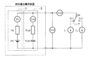
図4のブロック図では図示しなかったが、実際に燃料電池1を用いて発電を行うには、上記スタック構造を有する燃料電池本体の他に所定の周辺装置を必要とする。図5は、燃料電池1とその周辺装置とからなる燃料電池システム30の構成を示すブロック図である。
【0031】
図5において、燃料電池1の空気極側に接続されたエアコンプレッサ11は、例えば、燃料電池1の空気極に加えて、レギュレータ17に対する信号圧として空気を供給する。このため、エアコンプレッサ11を駆動するモータ(図示略)には、回転数指令値Nが制御装置4から入力されている。モータは入力された回転数指令値Nに基づいてエアコンプレッサ11を駆動し、これによりエアコンプレッサ11は、フィルタ12を介して外部から取り込んだ空気を加圧して熱交換機13に供給する。加圧された空気は熱交換器13によって冷却され、フィルタ14により塵が除去される。
【0032】
加湿器15に供給された空気は、加湿されて燃料電池1へと供給され、上述した電気化学反応後、燃料電池1に供給される空気の圧力を調整するために設けられた空気調圧弁16を通過し、排出される。
一方、燃料供給側に設けられたレギュレータ(比例圧力レギュレータとも呼ばれる)17は、空気供給側から供給された空気の圧力(パイロット信号)に基づいて高圧水素タンク18から燃料電池1へ供給される水素の圧力を調整する。このように、燃料電池1の空気供給側と燃料供給側の圧力はレギュレータ17によってバランス制御される。
【0033】
高圧水素タンク18から供給される水素は高圧であるため、電動遮断弁19によりその圧力が一時低下された後にレギュレータ17により圧力調整され、エゼクタ20を介して加湿器15へと供給される。加湿器15により加湿された水素は燃料電池1の燃料極側へ供給され、電気化学変化後、排出ガスとなってデミスタ21に出力される。デミスタ21では、供給された排出ガスが気液分離され、気体である水素はエゼクタ20を経て水素の供給部に循環、再利用される。
また、水素ガスの排出側には、燃料電池及びデミスタ内部に滞留した水を排出するためのパージバルブ22が設けられている。
なお、上述した電動遮断弁19は、高圧水素タンク18からの水素ガスの供給を遮断する働きも備えている。
【0034】
また、ウォーターポンプ40、41は、ラジエータ23、24により放熱、冷却された冷却水を燃料電池1及び補機/制御装置内に循環させるものであり、このように冷却水を循環させて、燃料電池1及び補機/制御装置の温度を所定の温度以下に制御する。ここでは、ウォーターポンプ40は、燃料電池1及び補機/制御装置の各部を冷却し、燃料供給側を加熱するために設けられ、ウォーターポンプ41は空気供給側の各部を冷却するために設けられている。
【0035】
上述した補機/制御装置においては、エアコンプレッサ11や空気極排気側の流路に設けられた空気調圧弁16に対して駆動信号を出力し、この駆動量や開閉状態を調整することで反応ガス供給量を制御して燃料電池1の発電力を調整している。
【0036】
以上、燃料電池電源装置10の構成について説明したが、次に、この燃料電池電源装置10に規定の負荷変動量が与えられた場合に、燃料電池1へ供給される反応ガス量について説明する。
【0037】
まず、図6に本実施形態に係る燃料電池電源装置10の等価回路を示す。同図においてVfcは燃料電池の起電力、Rfcは燃料電池の内部抵抗、Ifcは燃料電池を流れる電流である。同様にキャパシタ2において、Vcapは充電電圧、Rcapは内部抵抗、Icapは流れる電流である。Voutは燃料電池電源装置10の出力電圧であり、Ioutは燃料電池電源装置10を流れる電流である。
【0038】
上述したような回路で示される燃料電池電源装置10において、負荷変動が生じた場合の燃料電池電源装置10の動作について、以下説明する。
ここでは説明の便宜上、負荷電流がI1からI2にステップ応答的に変化した場合について説明する。なお、実際の車両走行時における負荷変動はステップ応答ではない。
【0039】
このような負荷電流の変動が生じた場合、制御装置4は燃料電池電源装置10に対して負荷変動に見合った出力、即ち負荷電流I2に対応する出力を要求する。しかしながら、図5に示したように、燃料電池1は、補機であるエアコンプレッサ11を駆動するモータに対して負荷変動に応じた回転数指令値Nが制御装置4から発信され、これによりモータの回転数が上がり、この結果、反応ガスの供給量が増加し、その後、燃料電池1内で電気化学反応が生じて初めて出力が得られるものであるので、燃料電池1の出力が負荷変動に応じた電力となるまでに時間を要する。
従って、上述したような燃料電池1の応答遅れの期間、燃料電池1に並列に接続されたキャパシタ2が走行用モータ3に対して電力を供給することにより、負荷変動に応じた出力を達成している。
しかしながら、キャパシタ2は図6に示したように、内部抵抗Rcapを有しているため、電力を供給することによって増加した電流分の電圧降下が生じる。
図7に、負荷電流IoutがI1からI2にステップ応答的に変化した場合における燃料電池電源装置10の出力電圧Voutの推移(応答特性)を示す。なお、図7(a)に出力電圧の応答特性を示し、図7(b)に負荷電流の応答特性を示す。
【0040】
同図に示すように、まず負荷変動前(時刻t0前)では、負荷電流I1に応じた電圧、即ちVout=Vfc−(Rfc×I1)で平衡状態となっている。
時刻t0において負荷変動が生じると、変動直後においては、キャパシタ2は負荷変動に応じた電力を供給しようとするために電流Icapが急激に増加するため、この電流によって電圧降下(ΔV=Rfc×Ifc2=Rcap×Icap2)が生じる。その後、出力電圧Voutはキャパシタ2の放電によって徐々に減少し、Vout=Vfc−(Rfc×I2)となった時点で平衡状態となる。従って、Vout=Vfc−(Rfc×I2)への収束状態は、キャパシタ2の静電容量が大きいほど傾きが小さくなり平衡状態となるまでに、より長い時間を要することとなる。また、負荷変動直後における電圧降下分は、キャパシタ2の内部抵抗R capが小さいほど小さい値となる。
【0041】
そして、上述したような負荷変動直後に電圧降下が生じると、即ち燃料電池1の応答期間内において出力電圧VoutがΔV降下すると、燃料電池1は出力電圧に対して反応ガス量が不足する状態、いわゆるガス欠状態に陥る。
このようなガス欠状態が続く、或いは頻繁に発生すると、燃料電池内の固体ポリマーイオン交換膜等からなる固体高分子電界質膜内に含まれている水分が欠乏することにより、水素イオンがこの膜を透過する際の抵抗が高くなるため、膜の劣化が生じ、燃料電池の寿命が短くなる。
従って、このようなガス欠状態を防止するために、予め内部抵抗による電圧降下分に対応する反応ガス供給量(過剰供給量)を燃料電池1へ余分に供給しておく必要がある。
【0042】
この過剰供給量は、燃料電池電源装置10を構成するキャパシタ2の内部抵抗Rcap及び静電容量、規定の負荷変動幅、燃料電池1及び燃料電池システム30固有の特性値に基づいて設定される。
【0043】
例えば、上述の燃料電池1の特性値としては、燃料電池1の電流電圧特性(Vout=Vfc−(Rfc×Ifc))から導出される燃料電池電力及び内部抵抗が挙げられ、燃料電池システム30固有の特性値としては、後述する燃料電池の反応ガス供給系の応答速度特性が挙げられる。
以下、過剰供給量をどのように設定するかについて図1〜図3を参照して説明する。
【0044】
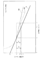
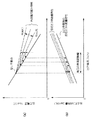
まず、キャパシタ2の内部抵抗Rcapが燃料電池1の内部抵抗Rfcより大きい場合における過剰供給量の設定について図1を参照して説明する。
同図において、線Aは燃料電池1の電流電圧特性を示しており、出力する電流値が小さいときには大きな電圧値を得ることができ、電流値が大きくなるに従って電圧値は低下する。そして、電流及び電圧で決まる座標が線Aよりも下側の領域にある場合には、燃料電池1はガス欠状態であると見なすことができる。
また、同図線B1は負荷変動前における燃料電池1への反応ガス供給量を最大に設定した場合の燃料電池電源装置10の電流電圧特性を示すものである。
上述したような電流電圧特性を持つ燃料電池1を備えた燃料電池電源装置10において、負荷電流を電流I1から電流I2までステップ応答的に変動させた場合について考える。
【0045】
ここで、例えば、負荷変動前における燃料電池1への反応ガス供給量を、燃料電池1が電流ILI1(但し、I1<ILI1<I2)まで出力可能である量に設定したとする。即ち、反応ガス量と平衡する燃料電池の出力電流がILI1となるように、反応ガス量を設定したとする。なお、この時、過剰供給量は電流ILI1−I1分の出力を可能とする反応ガス量に相当する。
この場合、電流ILI1以上の領域においては、燃料電池1の出力が間に合わず、負荷変動に対応する出力を得ることができないため、キャパシタ2によって出力が補助される。そして、負荷変動に対応する出力が燃料電池1によって行われるようになる迄の間、即ち、負荷変動に対する燃料電池1の応答期間、燃料電池電源装置10の出力はキャパシタ2の出力に依存することとなる。
【0046】
この結果、燃料電池電源装置10の電流電圧特性は、電流I1から電流ILI1の領域においては、燃料電池1とキャパシタ2の合成電流電圧特性、即ち同図中線B1で示す特性となり、電流ILI1以上の領域においては、キャパシタ2の電流電圧特性、即ち同図中線D1となる。なお、線D1で示されるキャパシタ2の電流電圧特性は、Vout=Vcap−(Icap×Rcap)で表される(但し、Rcap>Rfc、且つVcapは一定とする)。
【0047】
そして、負荷変動直後、即ち電流I2における燃料電池電源装置10の出力電圧は、線D1からVd1と導出することができ、これにより、電流I1から電流I2までステップ応答的に負荷変動を与えた場合の燃料電池電源装置10の電圧降下量ΔVは、電流I1における出力電圧V1から電流I2における出力電圧Vd1を引いた値となる。
一方、燃料電池1が出力可能な電圧値は、負荷変動前において供給されている反応ガス量と平衡する出力電流に対応する電圧値であるから、線Aから電圧VLI1となる。即ち、負荷変動直後における燃料電池1の出力電圧許容量ΔV’は、電流I1における出力電圧V1から電流IIL1における出力電圧VIL1を引いた値となる。
【0048】
従って、負荷変動前に燃料電池1に予め供給されている反応ガス量による出力電圧許容量ΔV’が、負荷変動直後における電圧降下量ΔVよりも大きいため、負荷変動直後において燃料電池1がガス欠状態に陥ることを回避することができる。
このように、負荷変動が与えられた直後の燃料電池電源装置10の出力電圧Vd1が、負荷変動前に燃料電池1に供給されている反応ガス量と平衡する燃料電池の出力電流に対する電圧値VLI1よりも高くなるように、燃料電池に供給する出力平衡時の反応ガス量に対する過剰供給量を設定することにより、上述した燃料電池1のガス欠状態を回避することが可能となる。
【0049】
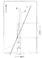
次に、図2を参照して、キャパシタ2の内部抵抗Rcapが燃料電池1の内部抵抗Rfcと等しい場合について説明する。
図2に示す線Aは図1と同様の燃料電池1の電流電圧特性を示している。
また、同図線B2は負荷変動前における燃料電池1への反応ガス供給量を最大に設定した場合の燃料電池電源装置10の電流電圧特性を示すものである。ここでは、キャパシタ2の内部抵抗Rcapは燃料電池1の内部抵抗Rfcに等しいため燃料電池電源装置10の電流電圧特性B2は、図1に示した電流電圧特性B1に比べ、傾きが緩やかな直線となる。
このような燃料電池電源装置10において、負荷電流を電流I1から電流I2までステップ応答的に変動させた場合について考える。
【0050】
ここで、例えば、負荷変動前における燃料電池1への過剰供給量を、燃料電池1が電流ILI2(但し、I1<ILI2<I2)まで出力可能である量に設定した場合、即ち、反応ガス量と平衡する出力電流がILI2となるように、反応ガス量を設定した場合には、上述した図1と同様、電流ILI2以上の領域においては、燃料電池1の出力が間に合わず、負荷変動に対応する出力を得ることができないため、キャパシタ2によって出力が補助される。なお、この時、過剰供給量は電流ILI2−I1分の出力を可能とする反応ガス量に相当する。
このため、燃料電池電源装置10の電流電圧特性は、電流I1から電流ILI2の領域においては、燃料電池1及びキャパシタ2の合成電流電圧特性、即ち図2中線B2で示す特性となり、電流ILI2以上の領域においては、キャパシタ2の電流電圧特性、即ち線D2となる。
【0051】
ここで、線C2で示されるキャパシタ2の電流電圧特性は、Vout=Vcap−(Icap×Rcap)で表される直線となり(但し、Vcapは一定とする)、また、Rcap=Rfcなので、線D2の傾きは燃料電池1の電流電圧特性である線Aの傾きと等しくなる。
そして、電流I2における燃料電池電源装置10の出力電圧は、線D2からVd2と求めることができる。そして、負荷電流がI1からI2にステップ応答的に変動した場合におけるキャパシタ2の内部抵抗Rcapによる電圧降下量ΔVは、図1で説明したように、図2に示す値となる。
【0052】
一方、負荷変動前において、燃料電池1に供給されている反応ガス量と平衡する出力電流に対応する電圧値は、線Aの特性からVLI2となり、この電圧値まで燃料電池1は出力可能であるということができる。これにより、負荷電流I1から負荷電流I2における燃料電池1の出力電圧許容量ΔV’は、図2中ΔV’で示される値となる。
この結果、負荷変動直後においてキャパシタ2の内部抵抗Rcapによる電圧降下ΔVが生じても、燃料電池1にはその電圧降下分を考慮した過剰供給量が予め供給されているため、負荷変動直後においてガス欠状態に陥ることを回避することができる。
【0053】
次に、図3を参照して、キャパシタ2の内部抵抗Rcapが燃料電池1の内部抵抗Rfcよりも小さい場合について説明する。
図2に示す線Aは図1と同様の燃料電池1の電流電圧特性を示している。
また、同図線B3は負荷変動前における燃料電池1への反応ガス供給量を最大に設定した場合の燃料電池電源装置10の電流電圧特性を示すものである。ここでは、キャパシタ2の内部抵抗Rcapは燃料電池1の内部抵抗Rcapよりも小さいため、燃料電池電源装置10の電流電圧特性B3は、図2に示した電流電圧特性B2よりも更に傾きが緩やかな直線となる。
このような燃料電池電源装置10において、負荷電流を電流I1から電流I2までステップ応答的に変動させた場合について考える。
【0054】
ここで、例えば、負荷変動前における燃料電池1への過剰供給量を、燃料電池1が電流ILI3(但し、I1<ILI3<I2)まで出力可能である量に設定した場合、即ち、反応ガス量と平衡する出力電流ILI3がとなるように反応ガス量を設定した場合には、上述した図1と同様、電流ILI3以上の領域においては、燃料電池1の出力が間に合わず、負荷変動に対応する出力を得ることができないため、キャパシタ2によって出力が補助される。なお、この時、過剰供給量は電流ILI3−I1分の出力を可能とする反応ガス量に相当する。
このため、燃料電池電源装置10の電流電圧特性は、電流I1から電流ILI3の領域においては、燃料電池1及びキャパシタ2の合成電流電圧特性、即ち図3中線B3で示す特性となり、電流ILI3以上の領域においては、キャパシタ2の電流電圧特性、即ち線D3となる。
【0055】
ここで、線C3で示されるキャパシタ2の電流電圧特性は、Vout=Vcap−(Icap×Rcap)で表される直線となり(但し、Vcapは一定とする)、また、Rcap<Rfcなので、線D3の傾きは図1及び図2に示したいずれのキャパシタ2の電流電圧特性よりも傾きが小さくなる。
そして、電流I2における燃料電池電源装置10の出力電圧は、線D3からVd3と求めることができる。そして、負荷電流がI1からI2にステップ応答的に変動した場合におけるキャパシタ2の内部抵抗Rcapによる電圧降下量ΔVは、図1で説明したように、図3に示す値となる。
【0056】
一方、負荷変動前において、燃料電池1に供給されている反応ガス量と平衡する出力電流に対応する電圧値は、線Aの特性からVLI3となり、この電圧値まで燃料電池1は出力可能であるということができる。これにより、負荷電流I1から負荷電流I2における燃料電池1の出力電圧許容量ΔV’は、図3中ΔV’で示される値となる。
この結果、負荷変動直後においてキャパシタ2の内部抵抗Rcapによる電圧降下ΔVが生じても、燃料電池1にはその電圧降下分を考慮した反応ガス量が予め供給されているため、負荷変動直後においてガス欠状態に陥ることを回避することができる。
【0057】
なお、上述した図1、図2及び図3の場合において、上記条件を満たす過剰供給量の内、最も小さい値を適用することにより、反応ガス供給量のロスを軽減させ、効率よく燃料を供給することが可能となる。
【0058】
以上、過剰供給量の設定について図1〜図3を参照してそれぞれの場合において説明してきたが、以下に述べるような手法により過剰供給量を設定することも可能である。以下、図10を参照し、他の過剰供給量の設定手法について説明する。
図10(a)の実線は、燃料電池1の電流電圧特性を示している。また、図10(a)の点線は、燃料電池1とキャパシタ2の合成電流電圧特性であり、当該点線で示した特性の起点(図中平衡点U)は、燃料電池1とキャパシタ2とが直結状態で接続されている平衡点である。
一方、図10(b)の実線は、燃料電池1の出力平衡時の反応ガス供給量Qairの特性を示している。同図に示すように、電流が増加するほど、燃料電池1へ供給する反応ガス供給量は増加する。また、図10(b)の点線は電流負荷変動による電圧降下による燃料電池1のガス欠状態を回避するための過剰供給量を加味した反応ガス供給量特性(以下、単に反応ガス供給量特性と記載する)を示している。この反応ガス供給量特性についての詳細は後述する。
【0059】
図10(a)に実線で示されている燃料電池1の電流電圧特性は、図10(b)に実線で示した反応ガス供給量に依存している。即ち、電流値がIfc=I1である状態において、反応ガス供給量としてQa1’を燃料電池1へ供給した結果、出力電圧としてV1が得られる。換言すると、図10(b)の実線の特性は、図10(a)に実線で示した燃料電池1の電流電圧特性を得るために必要最低限の反応ガス供給量であるといえる。なお、このような関係を持つことから、この出力平衡時の反応ガス供給量特性上の反応ガス供給量を平衡反応ガス供給量とする。
【0060】
次に、図10を用い、過剰供給量の算出方法について説明する。
電流負荷変動として、電流がI1からI2(過剰供給量算定のために想定した規定の負荷変動幅ΔI)へ変動すると想定した場合、電流I2に対応する燃料電池1とキャパシタ2の合成出力電圧V2を図10(a)より求める。
次に、この合成出力電圧V2に対応する燃料電池1の出力電流Ifc2’を燃料電池1の電流電圧特性から求め、この出力電流Ifc2’に対応する平衡反応ガス供給量Qa1を図10(b)の出力平衡時の反応ガス供給両特性から求める。こうして求められた平衡反応ガス供給量Qa1を電流I1の時点で燃料電池1へ供給する反応ガス供給量とする。ここで、電流Ifc=I1における平衡反応ガス供給量Qa1からQa1を減算した値が、過剰供給量となる。
【0061】
このように、負荷変動が起きた場合に生ずる電圧降下分に対応する反応ガス供給量を過剰供給量として電流I1の時点で予め供給しておけば、燃料電池1のガス欠を回避できる。そして、上述の手法により求められた過剰供給量を加味する反応ガス供給量特性を示したものが、図10(b)の点線となる。
【0062】
ところで、図10(a)に示した燃料電池1の電流電圧特性は過剰供給量の説明を簡易にするために用いた特性曲線の一部であり、実際は、図11(a)実線のような特性曲線となる。即ち、燃料電池1の電流電圧特性は直線特性ではなく、図11(a)に実線で示すような特性曲線を示す。また、この図における点線は、任意に定めた平衡点を起点とした燃料電池1とキャパシタ2との合成電流電圧特性である。
そして、上述したような燃料電池の特性曲線に対応する平衡反応ガス供給量は、図11(b)の実線で示すような特性となり、また、実際に燃料電池1へ供給される反応ガス供給量は図11(b)の点線で示す特性曲線となる。
【0063】
次に、図12を用いてキャパシタ2の内部抵抗Rcapの抵抗値の変化に応じた合成電流電圧特性と過剰供給量との関係について説明する。
図12(a)に示すように、キャパシタ2の内部抵抗Rcapが大きくなるほど燃料電池1とキャパシタ2の合成電流電圧特性の傾きは大きくなる。従って、図10で説明した過剰供給量の算出方法に基づいて図12(a)に示した各電流電圧特性に対応する反応ガス供給量特性を求めると、図12(b)に示すように、キャパシタ2の内部抵抗Rcapが大きいほど、過剰供給量を大きく設定することが必要となる。逆に、過剰供給量を少なくしたい場合には、できるだけ内部抵抗Rcapが小さいキャパシタ2を選定すればよいこととなる。
【0064】
次に、図13を用いてキャパシタ2の静電容量と燃料電池1へ反応ガスを供給する反応ガス供給系の応答特性との関係ついて説明する。なお、ここで反応ガス供給系とは、燃料電池1と図5に示したエアコンプレッサ11をはじめとする周辺装置(補機)であり、具体的には、エアコンプレッサ11、熱交換機13、高圧水素タンク18、電動遮断弁19、レギュレータ17、エゼクタ20、デミスタ21、加湿器15等が挙げられる。
【0065】
例えば、図13(a)に示すように、負荷電流がI1からI2へステップ応答的に変化した場合、燃料電池1とキャパシタ2との合成出力電圧Voutは、図13(b)に示すように、負荷電流変動(t0)の瞬間に電流I2に応じた電圧降下ΔV=Ifc2・Rfcを生じ、その後I2に対応する電圧V2まで過渡的に降下していく。
このとき、過渡時における合成出力電圧Voutの変化は、V(t)=Vfc・(1−e-(1/RC)t)で表すことができ、キャパシタ2の静電容量Cが大きいほど平衡状態(出力電圧がV2となる状態)となるまでに時間を要する。ここで、平衡状態となるまで時要する時間は、図13(b)に示すように、キャパシタ2の静電容量Cが大きいほど時間を要する。
【0066】
更に、図13(c)に反応ガス供給量の時間的推移を示す。同図において、それぞれの特性曲線は、上述した図13(b)に示した各特性曲線に対応しており、対応するそれぞれの特性曲線を同一の線種で示した。
ここで、図13(c)における各反応ガス量Qa1’、Qa1、Qa2’、Qa2は、それぞれ図14に示すように、負荷変動前における負荷電流I1に対応する平衡反応ガス供給量Qa1’、負荷電流I1における過剰供給量を加味した反応ガス供給量Qa1、負荷変動後における負荷電流I2に対応する平衡反応ガス供給量Qa2’、負荷電流I2に対応する過剰供給量を加味した反応ガス供給量Qa2に対応している。
【0067】
ここで、燃料電池1へ供給する反応ガス供給量が、変動前の反応ガス供給量Qa1から負荷変動後における平衡反応ガス供給量Qa2’に達するまでの応答時間を、上記キャパシタ2の出力補助作動時間よりも短くすることが必要となる。これは、キャパシタ2が上記負荷変動に対する出力補助可能な時間(出力補助作動時間)内に、負荷変動後の電流I2に対応した出力を燃料電池1だけで供給できるような状態にしなければ、要求出力に対して燃料電池1及びキャパシタ2の出力が不足する状態が生じ、この結果、燃料電池1がガス欠状態となってしまうからである。
【0068】
従って、図13(c)に示すように、キャパシタ2による出力補助が可能である時間内に、即ち、図13(b)において燃料電池1とキャパシタ2との合成出力電圧がV2に達してしまう前に、燃料電池1へ供給する反応ガス供給量を値Qa2’まで増加させることが必要となる。
これにより、上述したような条件を満たすような応答特性を有する反応ガス供給系、又は、上記条件を満たすような静電容量のキャパシタ2を適用する必要がある。
【0069】
次に、上述したキャパシタの静電容量と反応ガス供給系の応答特性について、図9を参照して更に詳しく説明する。
図9は燃料電池電源装置10の負荷変動時の応答特性を示した図である。同図において、アクセルペダルが運転者等によって踏み込まれることにより、アクセルペダルの変化量に応じた要求トルクApは時刻T0から時刻T2にかけてI1からI2へ変化する。この要求トルクApの変化に伴い、モータ要求値Imotも少しの遅れ時間を持ちながら同様に電流I1からI2へと変化する。
【0070】
一方、燃料電池に供給される反応ガス量の応答特性として、ここではエアコンプレッサ11によって供給される反応ガス量と平衡するエアコンプレッサ11の回転数を示した。負荷変動前のT0以前における反応ガス量と平衡する回転数はNm1であり、上述したモータ要求値Imotの変化開始後から所定の遅れ時間後、例えば時刻T1において緩やかに変化を始め、時刻T3において負荷変動後の出力電流I2に対応する回転数Nm2に達し、その後、更に上昇を続け、最終的には負荷変動後の回転数Nm2に過剰供給量を加味した回転数で平衡状態となる。
【0071】
燃料電池1の出力電流I fcは、負荷変動開始後から反応ガス量の変化に伴って電流値が上昇し、時刻T4において、負荷変動後の平衡電流である電流値I2に達し、その後、一時電流値I2を上回る出力を続けた後、電流値I2に収束する。
一方、キャパシタ2は、燃料電池1の出力が不足する期間において放電を行い、出力を補う。このためキャパシタ2の電流特性は、時刻T1において放電を開始し、以後、燃料電池1の出力電流I fcが平衡状態となるまで燃料電池1の出力電流I fcに伴って変化する。
この結果、燃料電池1の出力電流I fcとキャパシタ2の出力電流I capとの合成出力電流Iallは、要求トルクApを満足するように変化する。
【0072】
一方、燃料電池1とキャパシタ2の合成電圧出力であるVoutは、時刻T1から徐々に減少し、時刻T5において負荷電流変化後の平衡電圧値となる。
そして図9に示したように、予め規定した負荷変動が与えられた場合に、燃料電池1の反応ガス供給系から燃料電池1に供給される反応ガス量が、時刻T0の前記負荷変動直前の供給量、即ちエアコンプレッサ11の回転数Nm1に平衡する供給量から、燃料電池1が負荷変動後の出力電流値(例えばI2)を少なくとも出力するのに必要な供給量(図9では、回転数Nm2に平衡する供給量)に達するまでに要する反応ガス供給系の応答時間、即ち時刻T0から時刻T3までの応答時間が、負荷変動時点T0から燃料電池1とキャパシタ2との合成出力電圧Voutが、負荷変動後の燃料電池1の平衡電流I2に対応する電圧値V2に達するまでのキャパシタ2による出力補助作動時間、即ち時刻T0から時刻T5までの期間、よりも短くなるように燃料電池1に供給する出力平衡時の反応ガス量に対する過剰供給量及びキャパシタ2の特性値を設定する。
【0073】
このように、燃料電池電源装置10に対して、予め規定した負荷変動が与えられた場合に、負荷変動後において燃料電池1及びキャパシタ2の合成出力電圧が負荷変動後の平衡電流に対応する電圧に達する前に、燃料電池1への反応ガス供給量が負荷変動後の平衡電流を少なくとも出力するのに必要な供給量に達するように燃料電池1に供給する出力平衡時の反応ガス量に対する過剰供給量及びキャパシタ2の特性を設定することにより、燃料電池1がガス欠状態に陥ることを防止することができる。
【0074】
なお、反応ガス供給系が燃料電池1へ供給する反応ガス供給量は、制御装置4によって演算される目標発電量に基づいて設定される。この目標発電量は、制御装置4が、アクセルペダル開度、車速、電装補機消費電力等の車両の走行状態を示す種々の入力信号に基づいて所定間隔毎に演算する値である(図4参照)。従って、過剰供給量を考慮した反応ガス量を燃料電池1へ供給するためには、制御装置4が過剰供給量を考慮して目標発電量を演算する必要がある。
即ち、図8(a)に示したような負荷出力が生じた場合には、制御装置4は、図8(b)に示すように、過剰供給量に対応する発電量を加えた目標発電量を設定する。これにより、時刻t0において負荷出力がステップ的に増加し、電圧降下が発生しても、電圧降下分に対応する反応ガス量が予め燃料電池1へと供給されていることとなるので、燃料電池1のガス欠を防止することができる。
【0075】
更に、制御装置4は、上述したように所定の間隔毎に目標発電指令値を演算しているわけであるが、連続して求められた2つの目標発電指令値、例えば、演算された最新の目標発電指令値と、その直前に設定した目標発電指令値とに基づく負荷変動幅が、過剰供給量を設定するために想定した上記規定の負荷変動幅以下となるように最新の目標発電指令値を設定する。
即ち、車両の走行状態を示す種々の入力信号に基づいて目標発電指令値を設定したときに、直前に算出した目標発電指令値との関係で、負荷変動幅が規定の負荷変動幅ΔIを越えてしまう場合には、その増加分がΔI以下となるように、最新の目標発電値を補正する。
このような補正を行うのは、過剰供給量を上記規定の負荷変動幅ΔIに基づいて設定しているにも拘わらず、これ以上の負荷変動幅を与えてしまうと、要求出力に対して燃料電池1の出力が間に合わなくなり、結果、ガス欠状態となってしまうからである。
従って、制御装置4が上記条件を満たすように目標発電指令値を常に設定することにより、反応ガス供給量が不足するような出力要求を燃料電池1に対して要求しないように制御するので、燃料電池1のガス欠を防ぐことができる。
【0076】
なお、上述してきたように、本実施形態に係る燃料電池電源装置では、燃料電池1とキャパシタ2とを直結状態で使用しているが、実際は、燃料電池1とキャパシタ2との間には燃料電池1の出力電流を制御するための電流制限装置(図示略)が設けられている。以下、この電流制限装置について図1を参照して説明する。
【0077】
例えば、車両の起動直後においては、主にキャパシタ2から電力を供給する。これにより、キャパシタ2の残容量は急激に低下するため、キャパシタ2の電位は燃料電池1の電位に比べてかなり低い値となる。このような状態で、キャパシタ2と燃料電池1とを直結状態としてしまうと、燃料電池1からキャパシタ2へ大きな電流が流れるため、燃料電池1の電位も急激に低下してしまう。
【0078】
これにより、燃料電池1は、燃料電池1の出力に対して反応ガスの供給が追いつかない状態、いわゆるガス欠状態に陥ってしまう。従って、キャパシタ1と燃料電池2との電位差が大きい期間においては、燃料電池1がガス欠状態とならないようにその出力電流を制限する必要がある。このため、本発明では、キャパシタ2と燃料電池1との電位差が大きくなる起動時においては、電流制限装置(図示略)によって燃料電池1からの出力電流を制御しながらキャパシタ2を充電し、また、燃料電池1とキャパシタ2との電位差が、予め設定された電位差以下となった場合には、電流制限装置による燃料電池1の出力電流の制御を停止して、キャパシタ2と燃料電池1とを直結状態として使用する。
【0079】
結局、起動時においては、従来と同様に燃料電池1のガス欠を防止するために燃料電池1とキャパシタ2との間には、チョッパ型DC/DCコンバータ等からなる電流制限装置が設けられており、電流制限装置内のスイッチング素子がオン/オフすることにより、燃料電池1の出力電流を制限する。しかしながら、車両の起動後において燃料電池1とキャパシタ2の電位差が小さくなり、燃料電池1の出力電流を制限しなくてもよい状態になると、電流制限装置はスイッチング動作を停止し、スイッチング素子がオン状態に固定され、キャパシタ2と燃料電池1とが直結状態となる。
このように、実際の装置構成としては、燃料電池1とキャパシタ2との間に電流制御装置が介在するのであるが、本実施形態で説明してきたような実使用時においては、電流制限装置はスイッチング動作を行わなくなるので、あたかも燃料電池1とキャパシタ2との間に電流制限装置が介在しないような状態となる。
【0080】
以上、この発明の実施形態を図面を参照して詳述してきたが、具体的な構成はこの実施形態に限られるものではなく、この発明の要旨を逸脱しない範囲の設計等も含まれる。
【0081】
【発明の効果】
以上説明したように、本発明の燃料電池電源装置によれば、電気負荷の変動時に生じる電気二重層キャパシタの内部抵抗に応じた電気負荷への電圧降下分に対応して、反応ガス量を過剰に供給するので、また、所定の出力状態において、該出力状態における燃料電池の電流電圧特性上の平衡点を起点とした燃料電池と電気二重層キャパシタとの合成出力特性と予め規定した負荷変動幅とに基づいて負荷変動後の燃料電池の電圧値を求め、該電圧値に対応する電流値を燃料電池の電流電圧特性に基づいて導出し、導出された電流値に対応する平衡反応ガス供給量を求め、求められた平衡反応ガス供給量以上の反応ガスを出力状態における反応ガス供給量として燃料電池へ供給するので、負荷変動直後に生じる電圧降下により、燃料電池がガス欠状態に陥るのを防止しつつ、燃料電池とキャパシタとを並列で使用することにより、電力効率の高い燃料電池電源装置を実現させることができるという効果が得られる。
また、上述した設定方法によって得られる過剰供給量によれば、前記電圧降下に対応するのに必要最小限の過剰供給量を求めることができるため、より反応ガスの無駄を排除し、効率よく燃料供給を行うことができる。
【0082】
また、本発明の燃料電池電源装置によれば、電気二重層キャパシタの内部抵抗、静電容量、負荷変動幅に応じて反応ガス供給量を設定するので、また、前記所定の出力状態における反応ガス供給量を、燃料電池の電流電圧特性と、電気二重層キャパシタの電流電圧特性と、燃料電池の電流電圧特性に対応する平衡反応ガス供給量特性とに基づいて設定するので、負荷変動直後に生じる電圧降下分を正確に導出することができ、上述の各設定値をより適切な値とすることが可能となる。これにより、燃料電池電源装置の性能向上を図ることが可能となる。
【0083】
また、本発明の燃料電池電源装置によれば、燃料電池の電流電圧特性が、燃料電池の内部抵抗値又は所定の出力電流区分範囲に対する平均抵抗値に依存するので、所定出力時において燃料電池へ供給される反応ガス供給量は、この燃料電池の内部抵抗に応じて異なることとなる。このように各種特性に基づいて適切な反応ガス量を設定することにより、負荷変動時における燃料電池のガス欠を防ぐと共に、最適な反応ガス量を燃料電池に供給することが可能となり、燃料電池電源装置の性能向上を図ることが可能となる。
【0084】
また、本発明の燃料電池電源装置によれば、電気二重層キャパシタの電流電圧特性が、電気二重層キャパシタの内部抵抗及び静電容量に依存するので、所定出力時において燃料電池へ供給される反応ガス供給量は、この電気二重層キャパシタの内部抵抗に応じて異なることとなる。このように各種特性に基づいて適切な反応ガス量を設定することにより、負荷変動時における燃料電池のガス欠を防ぐと共に、最適な反応ガス量を燃料電池に供給することが可能となり、効率よく反応ガスを使用することができ、燃料電池電源装置の性能向上を図ることが可能となる。
【0085】
また、本発明の燃料電池電源装置によれば、燃料電池の反応ガス供給系から燃料電池に供給されている反応ガス供給量が、出力状態における反応ガス供給量から負荷変動後における平衡反応ガス供給量に達するまでの応答時間を、負荷変動に対する電気二重層キャパシタの出力補助作動時間よりも短くするので、燃料電池がガス欠状態に陥ることを防止しつつ、燃料電池に対して効率よく燃料供給を行うことができ、又、電力効率の高い燃料電池電源装置を実現させることができるという効果が得られる。
【0086】
また、本発明の燃料電池電源装置によれば、反応ガス供給系の応答時間を電気二重層キャパシタの出力補助作動時間よりも短くするように反応ガス供給系の応答特性を設定するので、燃料電池がガス欠状態に陥ることを防止しつつ、燃料電池に対して効率よく燃料供給を行うことができ、又、電力効率の高い燃料電池電源装置を実現させることができるという効果が得られる。
【0087】
また、本発明の燃料電池電源装置によれば、反応ガス供給系の応答時間を電気二重層キャパシタの出力補助作動時間よりも短くするように電気二重層キャパシタの静電容量を設定するので、燃料電池がガス欠状態に陥ることを防止しつつ、燃料電池に対して効率よく燃料供給を行うことができ、又、電力効率の高い燃料電池電源装置を実現させることができるという効果が得られる。
【0088】
車両の走行状態を示す入力信号に基づいて所定間隔毎に走行用モータの目標出力指令値及び燃料電池の目標発電指令値が演算され、目標発電指令値に基づいて燃料電池へ供給される反応ガス量が設定される燃料電池電源装置であって、連続して求められた2つの目標発電指令値の変化量に基づく負荷変動幅が予め規定した負荷変動幅以内となるように制御されるので、反応ガス供給量が不足するような要求出力を要求しないように制御することにより、燃料電池のガス欠を防ぐことができる。
【0089】
また、本発明の燃料電池電源装置は、装置の起動時においては、燃料電池の出力電流を制限するために燃料電池と電気二重層キャパシタとの間に設けられた電流制限手段が動作し、また、燃料電池と電気二重層キャパシタとの電位差が、予め設定された電位差以下となった場合には、燃料電池と電気二重層キャパシタとを直結状態とする。このように、装置の起動後においては、電流制限装置を使用せずに燃料電池と電気二重層キャパシタとを直結状態とすることができるため、電流制限器のスイッチング素子によるスイッチング電力損失を回避することができ、電力を効率よく負荷へと供給することができるという効果が得られる。
【図面の簡単な説明】
【図1】 本発明の一実施形態による燃料電池の電流電圧特性図の一例である。
【図2】 同実施形態に係る燃料電池の電流電圧特性図の一例である。
【図3】 同実施形態に係る燃料電池の電流電圧特性図の一例である。
【図4】 同実施形態に係る燃料電池電源装置を燃料電池車両に搭載した場合の車両の概略構成図である。
【図5】 同実施形態に係る燃料電池及びその周辺装置の構成を示す図である。
【図6】 同実施形態に係る燃料電池電源装置の等価回路図である。
【図7】 同実施形態に係る燃料電池電源装置の電圧応答特性及び電流応答特性図である。
【図8】 同実施形態における燃料電池電源装置に係る各種出力特性を示す図である。
【図9】 同実施形態における燃料電池電源装置の各種応答特性図である。
【図10】 過剰供給量の設定手法について説明するための各種特性曲線の一部を示した図である。
【図11】 燃料電池の電流電圧特性とこの燃料電池の電流電圧特性に応じた反応ガス供給量特性を示す図である。
【図12】 電気二重層キャパシタの内部抵抗と反応ガス供給量の関係を示す図である。
【図13】 電気二重層キャパシタの静電容量と、反応ガス供給系の応答特性との関係を説明するための各種特性曲線である。
【図14】 出力電流に対応する各反応ガス供給量を導出するための反応ガス供給量特性を示した図である。
【符号の説明】
1…燃料電池、2…キャパシタ(電気二重層キャパシタ)、3…走行用モータ、4…制御装置、10…燃料電池電源装置、11…エアコンプレッサ[0001]
BACKGROUND OF THE INVENTION
The present invention relates to a fuel cell power supply apparatus that uses a fuel cell and an electric double layer capacitor in a directly connected state.
[0002]
[Prior art]
2. Description of the Related Art Conventionally, a hybrid fuel cell power supply device combining a fuel cell and an electric double layer capacitor (hereinafter simply referred to as a capacitor) is known as a driving power source for a fuel cell vehicle.
This hybrid type fuel cell power supply device supplies the necessary power stably by compensating for the power generation shortage caused by the response delay of the fuel cell at the time of transient fluctuation of the driving motor load, by the energy stored in the capacitor. .
[0003]
[Problems to be solved by the invention]
However,As described above, since a response delay occurs in a fuel cell at the time of a transient change, if an attempt is made to obtain an output corresponding to the load change immediately after the load change, a so-called gas shortage in which the fuel supply amount is insufficient with respect to the output. Fall into a stateThere was a problem.
[0004]
As a countermeasure, an output limiting device comprising a DC / DC converter or the like for controlling the output of the fuel cell is provided between the fuel cell and the capacitor, and the output gas of the fuel cell is supplied to the fuel cell by this output limiting device. There is also a method to control the amount suitable for the amount (air amount and fuel gas amount), but thisSince the output limiting device controls the output by causing the switching element provided therein to perform a switching operation (on / off operation at a high speed), there is a problem that power loss accompanying the switching operation is large.
In addition, the output limiting device needs to have a relatively large current capacity in order to be able to cope with the current output from the fuel cell, and there is a problem that the size of the device increases accordingly.
[0005]
The present invention has been made in view of such circumstances, and an object of the present invention is to provide a fuel cell power supply device with high power efficiency by using a fuel cell and an electric double layer capacitor in a directly connected state.
[0006]
[Means for Solving the Problems]
In order to achieve the above object, a fuel cell power supply device of the present invention includes a fuel cell (for example, fuel cell 1) and an electric double layer capacitor (capacitor 2) in parallel with an electric load (traveling motor 3). In the connected fuel cell power supply device (fuel cell power supply device 10), a voltage drop to the electric load according to the internal resistance (Rcap) of the electric double layer capacitor generated when the electric load varies (FIG. 7 (a) In response to ΔV) in FIG.Provided with excessive supply means (control device 4). thisExcess supply meansFor example, according to the internal resistance, capacitance, and load fluctuation range (I 2 -I 1 in FIG. 7B) of the electric double layer capacitorReactant gas supplySet (increase compensation).
Further, in a predetermined output state (the state of the output current Ifc = I1 in FIG. 10A), the balance in the current-voltage characteristics of the fuel cell in the output state (characteristic curve shown by a solid line in FIG. 10A) The combined output characteristics of the fuel cell and the electric double layer capacitor starting from the point (equilibrium point U in FIG. 10 (a)) (characteristic curve indicated by the dotted line in FIG. 10 (a)) and a predetermined load fluctuation range ( Based on ΔI shown in FIG. 10A, the voltage value of the fuel cell after the load change (V2 in FIG. 10A) is obtained, and the current value corresponding to the voltage value (in FIG. 10A) Ifc2 ′) is derived on the basis of the current-voltage characteristics of the fuel cell, the equilibrium reaction gas supply amount (Qa1 in FIG. 10B) corresponding to the derived current value is obtained, and the obtained equilibrium reaction gas supply More than the amount of reaction gas is output in the output state (FIG. As the reaction gas supply quantity in the state of the output current Ifc = I1) may be supplied to the fuel cell.
[0007]
According to the above-described configuration, an excessive amount of the reaction gas supplied to the fuel cell is given in advance in consideration of the voltage drop that occurs immediately after the load change. It is possible to prevent the gas supply amount from falling into a state where the required output is insufficient.
Further, according to the excess supply amount obtained by the above-described setting method, the minimum excess supply amount necessary to cope with the voltage drop can be obtained, so that waste of reaction gas is further eliminated and fuel is efficiently generated. Supply can be made.
[0008]
Further, in the fuel cell power supply device described above, the supply amount of the reaction gas in the output state is determined based on the current-voltage characteristics of the fuel cell (for example, the fuel cell indicated by the solid line in FIGS. 10A and 11A). Current-voltage characteristics), current-voltage characteristics of the electric double layer capacitor (for example, one characteristic element for deriving the combined current-voltage characteristics shown by the dotted line in FIG. 10A), and current-voltage characteristics of the fuel cell. It is set based on a corresponding equilibrium reaction gas supply amount characteristic (for example, a reaction gas supply amount characteristic curve at the time of output equilibrium indicated by a solid line in FIG. 10B).
[0009]
By setting the excess supply amount with respect to the reaction gas amount at the time of output equilibrium based on such characteristics, it is possible to accurately derive the voltage drop that occurs immediately after the load change, thus avoiding the out-of-gas condition of the fuel cell Therefore, it is possible to obtain the minimum amount of excess reaction gas required for the purpose.
[0010]
Furthermore, in the fuel cell power supply device described above, the current-voltage characteristic of the fuel cell depends on an internal resistance value of the fuel cell or an average resistance value with respect to a predetermined output current section range.
[0011]
Thus, since the current-voltage characteristics of the fuel cell depend on the internal resistance of the fuel cell, the amount of reaction gas supplied to the fuel cell at a predetermined output varies depending on the internal resistance of the fuel cell. Thus, by setting an appropriate amount of reaction gas based on various characteristics, it is possible to prevent the fuel cell from running out of gas when the load fluctuates and to supply the optimum amount of reaction gas to the fuel cell.
[0012]
Furthermore, in the fuel cell power supply device described above, a current-voltage characteristic of the electric double layer capacitor depends on an internal resistance of the electric double layer capacitor.
[0013]
Since the current-voltage characteristics of the electric double layer capacitor depend on the internal resistance of the electric double layer capacitor, the amount of reactant gas supplied to the fuel cell at a predetermined output depends on the internal resistance of the electric double layer capacitor. Different. Thus, by setting an appropriate amount of reaction gas based on various characteristics, it becomes possible to prevent the fuel cell from running out of gas at the time of load fluctuation and to supply the optimum amount of reaction gas to the fuel cell. A reactive gas can be used.
[0014]
Furthermore, in the fuel cell power supply device described above, the fuel cell reaction gas supply system (for example, peripheral devices (auxiliary devices) including the
[0015]
As described above, within the output auxiliary operation time of the electric double layer capacitor, the output of the fuel cell is in an equilibrium state, that is, the minimum amount of reaction gas necessary to output the load current after fluctuation is supplied to the fuel cell. Therefore, the fuel cell can be prevented from falling into a gas-out state.
[0016]
Furthermore, in the fuel cell power supply device described above, the response characteristic of the reaction gas supply system (that is, the figure) is set so that the response time of the reaction gas supply system is shorter than the output auxiliary operation time of the electric double layer capacitor. The response characteristic of COMP shown in FIG. 9 is set.
[0017]
As described above, by setting the response characteristics of the reaction gas supply system, the output of the fuel cell can be brought into an equilibrium state after a load change within the time when the output can be assisted by the electric double layer capacitor.
[0018]
Furthermore, in the fuel cell power supply device described above, the capacitance of the electric double layer capacitor is set so that the response time of the reaction gas supply system is shorter than the output auxiliary operation time of the electric double layer capacitor. It is characterized by that.
[0019]
As described above, by setting the capacitance of the electric double layer capacitor, the output of the fuel cell is in an equilibrium state, that is, the load current after fluctuation is output within the output auxiliary operation time of the electric double layer capacitor. Since the minimum required amount of reaction gas is supplied to the fuel cell, the fuel cell can be prevented from falling into a gas-out state.
[0020]
Further, in the fuel cell power supply device described above, an input signal (for example, the access shown in FIG.LeBased on various parameters such as pedal opening, vehicle speed, electrical accessory power consumption, etc., the target output command value of the driving motor and the target power generation command value of the fuel cell are calculated at predetermined intervals (actually, a predetermined clock The command values are calculated at regular intervals based on the target power generation command value, and the amount of reaction gas supplied to the fuel cell is set based on the target power generation command value. The load fluctuation range corresponding to the change amount (difference between the two command values) of the two obtained target power generation command values (for example, the latest target power generation command value and the target power generation command value obtained immediately before) Control is performed so as to be within a predetermined load fluctuation range (for example, a load fluctuation range ΔI in FIG. 14).
[0021]
According to such a configuration, control is performed so as not to output a required output such that the amount of reaction gas supplied to the fuel cell is insufficient, so that it is possible to avoid a shortage of gas in the fuel cell.
[0022]
Further, the fuel cell power supply device of the present invention includes a fuel cell and an electric double layer capacitor, and an output limiting means (for example, the chopper type DC / DC converter in the embodiment) is provided between the fuel cell and the electric double layer capacitor. The output limiting means controls the output current of the fuel cell (for example, a chopper type DC / DC) at the time of startup of the apparatus. In the case of a converter, the electric double layer capacitor is charged (with a switching operation of a switching element), and a potential difference between the fuel cell and the electric double layer capacitor is equal to or less than a preset potential difference (for example, a fuel cell and an electric If the fuel cell does not fall out of gas even if it is directly connected to the double layer capacitor), the fuel cell And the electric double layer capacitor are directly connected (for example, in the case of a chopper type DC / DC converter, the switching operation is stopped, the switching element is maintained in a conductive state, and the fuel cell and the electric double layer capacitor are It is characterized by being in a directly connected state).
[0023]
That is, when this fuel cell power supply device is mounted on a vehicle, power is supplied mainly from an electric double layer capacitor immediately after the vehicle is started (when the device is started). As a result, the remaining capacity of the electric double layer capacitor rapidly decreases, so that the electric double layer capacitor has a considerably lower potential than that of the fuel cell. In such a state, if the electric double layer capacitor and the fuel cell are directly connected, a large current flows from the fuel cell to the electric double layer capacitor, so that the output of the fuel cell is rapidly absorbed by the electric double layer capacitor. As a result, the potential of the fuel cell rapidly decreases. As a result, the fuel cell falls into a state where the supply of the reaction gas cannot catch up with the output of the fuel cell, that is, a so-called out-of-gas state. Therefore, during a period when the potential difference between the electric double layer capacitor and the fuel cell is large, it is necessary to limit the output current so that the fuel cell does not run out of gas.
Therefore, in the present invention, at the time of start-up when the potential difference between the
[0024]
DETAILED DESCRIPTION OF THE INVENTION
Hereinafter, an embodiment of the present invention will be described with reference to the drawings.
FIG. 4 is a schematic configuration diagram of a fuel cell vehicle equipped with the fuel cell power supply device 10 according to one embodiment of the present invention.
The fuel cell power supply device 10 according to the present embodiment is mounted on a vehicle and functions as electric power for driving the vehicle. The fuel cell power supply device 10 is a hybrid power supply device in which a
[0025]
On the other hand, when the driving force is transmitted from the driving wheel side to the traveling motor 3 side during deceleration of the fuel cell vehicle equipped with the fuel cell power supply device 10 according to the present embodiment, the traveling motor 3 serves as a generator. It functions to generate a so-called regenerative braking force, and recovers the kinetic energy of the vehicle body as electric energy. The traveling motor 3 is, for example, a permanent magnet type three-phase AC synchronous motor that uses a permanent magnet as a field, and is driven and controlled by three-phase AC power.
[0026]
The
The
[0027]
The control device 4 is configured as a logic circuit centered on a microcomputer, and includes a CPU, a ROM, a RAM, and input / output ports (not shown). The CPU executes a predetermined calculation according to a preset control program. The ROM stores in advance control programs and control data necessary for executing various arithmetic processes by the CPU, and the RAM temporarily stores various data necessary for executing various arithmetic processes by the CPU. Read and write. The input / output port inputs detection signals from various sensors such as a remaining capacity monitor, and outputs signals to the respective parts in accordance with the calculation results of the CPU to drive the fuel cell power supply 10 and the parts constituting the fuel cell vehicle. Control the state.
[0028]
For example, the control device 4 generates the target power generation based on various signals such as an accelerator pedal opening signal, a vehicle speed or a motor rotation speed signal, an electric accessory power consumption, and the like, which are input as parameters, and the driver depresses the accelerator pedal. The amount is calculated and transmitted to the fuel cell power supply 10, while the target output is transmitted to the traveling motor 3. Further, the remaining capacity of the capacitor is calculated based on various signals from a voltage sensor and a current sensor (not shown) provided in the
[0029]
In addition, in order to drive the fuel cell vehicle according to the present embodiment, in addition to the above-described components, various components, for example, a direct current supplied from the fuel cell power supply device 10 is converted into a three-phase alternating current. And an inverter supplied to the traveling motor 3, various sensors for detecting the voltage, voltage, temperature, etc. of the
[0030]
Although not shown in the block diagram of FIG. 4, in order to actually generate power using the
[0031]
In FIG. 5, the
[0032]
The air supplied to the
On the other hand, a regulator (also called a proportional pressure regulator) 17 provided on the fuel supply side is supplied with hydrogen supplied from the high-
[0033]
Since the hydrogen supplied from the high-
Further, a
The electric shut-off
[0034]
The water pumps 40 and 41 circulate the cooling water radiated and cooled by the radiators 23 and 24 in the
[0035]
In the above-mentioned accessory / control device, a drive signal is output to the
[0036]
The configuration of the fuel cell power supply device 10 has been described above. Next, the amount of reaction gas supplied to the
[0037]
First, FIG. 6 shows an equivalent circuit of the fuel cell power supply device 10 according to the present embodiment. In the figure, Vfc is the electromotive force of the fuel cell, Rfc is the internal resistance of the fuel cell, and Ifc is the current flowing through the fuel cell. Similarly, in the
[0038]
The operation of the fuel cell power supply 10 when a load change occurs in the fuel cell power supply 10 shown by the circuit as described above will be described below.
Here, for convenience of explanation, the load current is I1To I2A case where the step response is changed will be described. Note that the load fluctuation during actual vehicle travel is not a step response.
[0039]
When such a change in load current occurs, the control device 4 outputs to the fuel cell power supply device 10 an output corresponding to the load change, that is, the load current I.2Request output corresponding to. However, as shown in FIG. 5, the
Therefore, during the response delay period of the
However, since the
FIG. 7 shows that the load current Iout is I1To I2Fig. 6 shows the transition (response characteristics) of the output voltage Vout of the fuel cell power supply device 10 when it is changed in a step response. FIG. 7A shows the response characteristic of the output voltage, and FIG. 7B shows the response characteristic of the load current.
[0040]
As shown in the figure, first, before the load change (before time t0), the voltage is in accordance with the load current I1, that is, Vout = Vfc− (Rfc × I1).
When a load change occurs at time t0, immediately after the change, the
[0041]
When the voltage drop occurs immediately after the load fluctuation as described above, that is, when the output voltage Vout drops by ΔV within the response period of the
If such a gas deficiency state continues or frequently occurs, the hydrogen ions contained in the solid polymer electrolyte membrane made of the solid polymer ion exchange membrane in the fuel cell are deficient. As the resistance through the membrane increases, membrane degradation occurs and the life of the fuel cell is shortened.
Therefore, in order to prevent such a gas shortage state, it is necessary to previously supply the
[0042]
This excess supply amount is set based on the internal resistance Rcap and capacitance of the
[0043]
For example, the characteristic value of the
Hereinafter, how to set the excessive supply amount will be described with reference to FIGS.
[0044]
First, the internal resistance Rcap of the
In the figure, line A shows the current-voltage characteristics of the
Further, the same line B1 shows the current-voltage characteristics of the fuel cell power supply 10 when the supply amount of the reaction gas to the
Consider a case where the load current is varied in a step-responsive manner from the current I1 to the current I2 in the fuel cell power supply device 10 including the
[0045]
Here, for example, the amount of reaction gas supplied to the
In this case, the current ILI1In the above region, the output of the
[0046]
As a result, the current-voltage characteristic of the fuel cell power supply device 10 is the current I1To current ILI1In this region, the combined current-voltage characteristic of the
[0047]
And immediately after the load change, that is, the current I2The output voltage of the fuel cell power supply device 10 in FIG.d1Thus, the current I1To current I2The voltage drop amount ΔV of the fuel cell power supply device 10 when the load change is given in a step-responsive manner up to the current I1Output voltage V1To current I2Output voltage Vd1The value obtained by subtracting
On the other hand, the voltage value that can be output by the
[0048]
Therefore, since the output voltage allowable amount ΔV ′ due to the amount of reaction gas supplied in advance to the
Thus, the output voltage V of the fuel cell power supply device 10 immediately after the load fluctuation is given.d1Is a voltage value V with respect to the output current of the fuel cell in equilibrium with the amount of reaction gas supplied to the
[0049]
Next, referring to FIG. 2, the internal resistance Rcap of the
A line A shown in FIG. 2 shows the current-voltage characteristic of the
Further, the same line B2 shows the current-voltage characteristics of the fuel cell power supply device 10 when the supply amount of the reaction gas to the
In such a fuel cell power supply device 10, consider a case where the load current is varied in a step-responsive manner from the current I1 to the current I2.
[0050]
Here, for example, the excess supply amount to the
Therefore, the current-voltage characteristic of the fuel cell power supply device 10 is the current I1To
[0051]
Here, the current-voltage characteristic of the
And current I2The output voltage of the fuel cell power supply device 10 in FIG.d2It can be asked. And the load current is I1To I2The voltage drop amount ΔV due to the internal resistance Rcap of the
[0052]
On the other hand, before the load change, the voltage value corresponding to the output current balanced with the amount of the reaction gas supplied to the
As a result, even if a voltage drop ΔV due to the internal resistance Rcap of the
[0053]
Next, referring to FIG. 3, the internal resistance Rcap of the
A line A shown in FIG. 2 shows the current-voltage characteristic of the
The line B3 in the figure shows the current-voltage characteristics of the fuel cell power supply device 10 when the supply amount of the reaction gas to the
In such a fuel cell power supply device 10, consider a case where the load current is varied in a step-responsive manner from the current I1 to the current I2.
[0054]
Here, for example, the excess supply amount to the
Therefore, the current-voltage characteristic of the fuel cell power supply device 10 is the current I1To current ILI3In this region, the combined current-voltage characteristic of the
[0055]
Here, the current-voltage characteristic of the
The output voltage of the fuel cell power supply 10 at the current I2 is the line D3Can be obtained as Vd3. When the load current fluctuates stepwise from I1 to I2, the voltage drop ΔV due to the internal resistance Rcap of the
[0056]
On the other hand, the voltage value corresponding to the output current balanced with the amount of the reaction gas supplied to the
As a result, even if a voltage drop ΔV due to the internal resistance Rcap of the
[0057]
In the case of FIGS. 1, 2 and 3 described above, by applying the smallest value among the excess supply amounts satisfying the above conditions, the loss of the reaction gas supply amount can be reduced and fuel can be efficiently supplied. It becomes possible to do.
[0058]
As described above, the setting of the excessive supply amount has been described in each case with reference to FIGS. 1 to 3, but it is also possible to set the excessive supply amount by the method described below. Hereinafter, another method for setting the excess supply amount will be described with reference to FIG.
The solid line in FIG. 10A shows the current-voltage characteristics of the
On the other hand, the solid line in FIG. 10B shows the characteristic of the reaction gas supply amount Qair when the output of the
[0059]
The current-voltage characteristics of the
[0060]
Next, a method for calculating the excess supply amount will be described with reference to FIG.
As the current load variation, the current is I1To I2If it is assumed that the load fluctuates to the specified load fluctuation range ΔI assumed for excess supply calculation, the current I2The combined output voltage V of the
Next, this combined output voltage V2Output current Ifc of the
[0061]
In this way, the reactive gas supply amount corresponding to the voltage drop that occurs when a load change occurs is defined as the excess supply amount and the current I1If the
[0062]
By the way, the current-voltage characteristic of the
The equilibrium reaction gas supply amount corresponding to the characteristic curve of the fuel cell as described above has a characteristic as shown by a solid line in FIG. 11B, and the reaction gas supply amount actually supplied to the
[0063]
Next, the relationship between the combined current-voltage characteristic corresponding to the change in the resistance value of the internal resistance Rcap of the
As shown in FIG. 12A, the slope of the combined current-voltage characteristic of the
[0064]
Next, the relationship between the capacitance of the
[0065]
For example, as shown in FIG.1To I2As shown in FIG. 13 (b), the combined output voltage Vout of the
At this time, the change in the combined output voltage Vout during the transition is V (t) = Vfc · (1−e-(1 / RC) t), And the larger the capacitance C of the
[0066]
Further, FIG. 13 (c) shows a temporal transition of the supply amount of the reaction gas. In the figure, each characteristic curve corresponds to each characteristic curve shown in FIG. 13B, and each corresponding characteristic curve is indicated by the same line type.
Here, each reactive gas amount Qa in FIG.1’, Qa1, Qa2’, Qa2Respectively, as shown in FIG. 14, the load current I before the load change1Equilibrium reaction gas supply Qa corresponding to1′, Load current I1Gas supply amount Qa taking into account excess supply amount1, Load current I after load change2Equilibrium reaction gas supply Qa corresponding to2′, Load current I2Reactive gas supply amount Qa with excess supply amount corresponding to2It corresponds to.
[0067]
Here, the reaction gas supply amount supplied to the
[0068]
Therefore, as shown in FIG. 13 (c), the output voltage of the
Accordingly, it is necessary to apply a reactive gas supply system having response characteristics satisfying the above-described conditions or a
[0069]
Next, the capacitance of the capacitor and the response characteristics of the reaction gas supply system will be described in more detail with reference to FIG.
FIG. 9 is a diagram showing the response characteristics of the fuel cell power supply device 10 when the load fluctuates. In the figure, when the accelerator pedal is depressed by a driver or the like, the required torque Ap corresponding to the amount of change in the accelerator pedal is changed from time T0 to time T0.2It changes from I1 to I2 over time. As the required torque Ap changes, the motor required value Imot also changes from the current I1 to I2 with a slight delay time.
[0070]
On the other hand, as the response characteristic of the amount of reaction gas supplied to the fuel cell, the number of revolutions of the
[0071]
Output current of fuel cell 1I fcThe current value increases with the change in the amount of reaction gas after the start of load fluctuation, reaches the current value I2 that is the equilibrium current after load fluctuation at time T4, and then continues to output exceeding the temporary current value I2. After that, it converges to the current value I2.
On the other hand, the
As a result, the output current of the fuel cell 1I fcAnd output current of capacitor 2I capThe combined output current Iall changes so as to satisfy the required torque Ap.
[0072]
On the other hand, Vout, which is a combined voltage output of the
Then, as shown in FIG. 9, when a predetermined load fluctuation is given, the fuel cell1Reactant gas supply system from fuel cell1From the supply amount immediately before the load fluctuation at time T0, that is, the supply amount that is balanced with the rotational speed Nm1 of the
[0073]
As described above, when a predetermined load change is given to the fuel cell power supply device 10, the combined output voltage of the
[0074]
The reaction gas supply amount supplied to the
That is, when the load output as shown in FIG. 8A occurs, the control device 4 adds the power generation amount corresponding to the excessive supply amount as shown in FIG. 8B. Set. As a result, time t0Even when the load output increases stepwise and a voltage drop occurs, the amount of reaction gas corresponding to the voltage drop is supplied to the
[0075]
Further, as described above, the control device 4 calculates the target power generation command value at every predetermined interval, but two target power generation command values obtained successively, for example, the latest calculated The latest target power generation command value so that the load fluctuation range based on the target power generation command value and the target power generation command value set immediately before is equal to or less than the load fluctuation range specified above for setting the excess supply amount. Set.
That is, when the target power generation command value is set based on various input signals indicating the running state of the vehicle, the load fluctuation range exceeds the specified load fluctuation range ΔI in relation to the target power generation command value calculated immediately before. In such a case, the latest target power generation value is corrected so that the increase is equal to or less than ΔI.
Such correction is performed when the excessive supply amount is set based on the prescribed load fluctuation range ΔI, but if a load fluctuation range larger than this is given, the fuel is output with respect to the required output. This is because the output of the
Therefore, since the control device 4 always sets the target power generation command value so as to satisfy the above-described conditions, the
[0076]
As described above, in the fuel cell power supply device according to the present embodiment, the
[0077]
For example, power is supplied mainly from the
[0078]
As a result, the
[0079]
After all, at the time of start-up, in order to prevent the
Thus, as an actual device configuration, the current control device is interposed between the
[0080]
The embodiment of the present invention has been described in detail with reference to the drawings. However, the specific configuration is not limited to this embodiment, and includes design and the like within a scope not departing from the gist of the present invention.
[0081]
【The invention's effect】
As described above, according to the fuel cell power supply device of the present invention,In response to the voltage drop to the electric load according to the internal resistance of the electric double layer capacitor that occurs when the electric load fluctuates, the reaction gas amount is excessively supplied.In a given output state, after a load change based on the combined output characteristics of the fuel cell and the electric double layer capacitor starting from the equilibrium point on the current-voltage characteristics of the fuel cell in the output state and a predetermined load fluctuation range The fuel cell voltage value is obtained, the current value corresponding to the voltage value is derived based on the current-voltage characteristics of the fuel cell, the equilibrium reactant gas supply amount corresponding to the derived current value is obtained, and the obtained equilibrium value is obtained. Since a reaction gas more than the reaction gas supply amount is supplied to the fuel cell as a reaction gas supply amount in the output state, the fuel cell is prevented from falling into a gas shortage state due to a voltage drop that occurs immediately after a load change. By using the capacitor in parallel, there is an effect that a fuel cell power supply device with high power efficiency can be realized.
Further, according to the excess supply amount obtained by the above-described setting method, the minimum excess supply amount necessary to cope with the voltage drop can be obtained, so that waste of reaction gas is further eliminated and fuel is efficiently generated. Supply can be made.
[0082]
Moreover, according to the fuel cell power supply device of the present invention,The reactive gas supply amount is set according to the internal resistance, capacitance, and load fluctuation range of the electric double layer capacitor.Since the reaction gas supply amount in the output state is set based on the current voltage characteristic of the fuel cell, the current voltage characteristic of the electric double layer capacitor, and the equilibrium reaction gas supply amount characteristic corresponding to the current voltage characteristic of the fuel cell, The voltage drop that occurs immediately after the load change can be accurately derived, and each of the above set values can be set to a more appropriate value. As a result, the performance of the fuel cell power supply device can be improved.
[0083]
Further, according to the fuel cell power supply device of the present invention, since the current-voltage characteristics of the fuel cell depend on the internal resistance value of the fuel cell or the average resistance value with respect to a predetermined output current section range, The amount of reaction gas supplied will vary depending on the internal resistance of the fuel cell. Thus, by setting an appropriate amount of reaction gas based on various characteristics, it becomes possible to prevent the fuel cell from running out of gas at the time of load fluctuation and to supply the optimum amount of reaction gas to the fuel cell. It becomes possible to improve the performance of the power supply device.
[0084]
Further, according to the fuel cell power supply device of the present invention, since the current-voltage characteristic of the electric double layer capacitor depends on the internal resistance and capacitance of the electric double layer capacitor, the reaction supplied to the fuel cell at a predetermined output time The gas supply amount varies depending on the internal resistance of the electric double layer capacitor. Thus, by setting an appropriate amount of reaction gas based on various characteristics, it becomes possible to prevent the fuel cell from running out of gas at the time of load fluctuation and to supply the optimum amount of reaction gas to the fuel cell. A reactive gas can be used, and the performance of the fuel cell power supply device can be improved.
[0085]
Further, according to the fuel cell power supply device of the present invention, the reaction gas supply amount supplied from the reaction gas supply system of the fuel cell to the fuel cell is changed from the reaction gas supply amount in the output state to the equilibrium reaction gas supply after the load change. Because the response time to reach the quantity is shorter than the output auxiliary operation time of the electric double layer capacitor with respect to the load fluctuation, the fuel cell is efficiently supplied to the fuel cell while preventing the fuel cell from going out of gas. In addition, it is possible to achieve a fuel cell power supply device with high power efficiency.
[0086]
Further, according to the fuel cell power supply device of the present invention, the response characteristic of the reaction gas supply system is set so that the response time of the reaction gas supply system is shorter than the output auxiliary operation time of the electric double layer capacitor. As a result, it is possible to efficiently supply fuel to the fuel cell while preventing the gas from running out of gas, and to achieve a fuel cell power supply device with high power efficiency.
[0087]
Further, according to the fuel cell power supply device of the present invention, the capacitance of the electric double layer capacitor is set so that the response time of the reaction gas supply system is shorter than the output auxiliary operation time of the electric double layer capacitor. While preventing the battery from running out of gas, it is possible to efficiently supply fuel to the fuel cell, and to achieve a fuel cell power supply device with high power efficiency.
[0088]
Reactive gas supplied to the fuel cell based on the target power generation command value is calculated based on the target power generation command value of the driving motor and the target power generation command value of the fuel cell at predetermined intervals based on the input signal indicating the running state of the vehicle. In the fuel cell power supply device in which the amount is set, the load fluctuation range based on the change amounts of the two target power generation command values obtained continuously is controlled so as to be within a predetermined load fluctuation range. By performing control so as not to request a required output that causes the reaction gas supply amount to be insufficient, it is possible to prevent the fuel cell from running out of gas.
[0089]
In the fuel cell power supply device of the present invention, the current limiting means provided between the fuel cell and the electric double layer capacitor operates to limit the output current of the fuel cell when the device is started. When the potential difference between the fuel cell and the electric double layer capacitor is equal to or less than a preset potential difference, the fuel cell and the electric double layer capacitor are brought into a direct connection state. As described above, after the device is started, the fuel cell and the electric double layer capacitor can be directly connected without using the current limiting device, so that switching power loss due to the switching element of the current limiter is avoided. Thus, the effect that power can be efficiently supplied to the load can be obtained.
[Brief description of the drawings]
FIG. 1 is an example of a current-voltage characteristic diagram of a fuel cell according to an embodiment of the present invention.
FIG. 2 is an example of a current-voltage characteristic diagram of the fuel cell according to the embodiment.
FIG. 3 is an example of a current-voltage characteristic diagram of the fuel cell according to the embodiment.
FIG. 4 is a schematic configuration diagram of a vehicle when the fuel cell power supply device according to the embodiment is mounted on a fuel cell vehicle.
FIG. 5 is a diagram showing a configuration of a fuel cell and its peripheral devices according to the embodiment.
FIG. 6 is an equivalent circuit diagram of the fuel cell power supply device according to the same embodiment.
FIG. 7 is a voltage response characteristic and current response characteristic diagram of the fuel cell power supply device according to the same embodiment;
FIG. 8 is a diagram showing various output characteristics according to the fuel cell power supply device in the same embodiment.
FIG. 9 is a graph showing various response characteristics of the fuel cell power supply device in the same embodiment.
FIG. 10 is a diagram showing a part of various characteristic curves for explaining a method of setting an excessive supply amount.
FIG. 11 is a diagram showing a current-voltage characteristic of a fuel cell and a reaction gas supply amount characteristic according to the current-voltage characteristic of the fuel cell.
FIG. 12 is a diagram showing the relationship between the internal resistance of the electric double layer capacitor and the reaction gas supply amount.
FIG. 13 is various characteristic curves for explaining the relationship between the capacitance of the electric double layer capacitor and the response characteristic of the reaction gas supply system.
FIG. 14 is a diagram showing a reaction gas supply amount characteristic for deriving each reaction gas supply amount corresponding to an output current.
[Explanation of symbols]
DESCRIPTION OF
Claims (11)
所定の出力状態において、該出力状態における燃料電池の電流電圧特性上の平衡点を起点とした燃料電池と電気二重層キャパシタとの合成出力特性と予め規定した負荷変動幅とに基づいて負荷変動後の燃料電池の電圧値を求め、該電圧値に対応する電流値を前記燃料電池の電流電圧特性に基づいて導出し、導出された前記電流値に対応する平衡反応ガス供給量を求め、求められた平衡反応ガス供給量に基づいた反応ガスを前記出力状態における反応ガス供給量として前記燃料電池へ供給する燃料電池電源装置。A fuel cell power supply device in which a fuel cell and an electric double layer capacitor are connected in parallel to an electric load,
In a given output state, after a load change based on the combined output characteristic of the fuel cell and the electric double layer capacitor starting from the equilibrium point on the current-voltage characteristic of the fuel cell in the output state and a predetermined load fluctuation range A current value corresponding to the voltage value is derived based on a current-voltage characteristic of the fuel cell, and an equilibrium reaction gas supply amount corresponding to the derived current value is obtained. A fuel cell power supply apparatus that supplies a reaction gas based on the supply amount of the equilibrium reaction gas to the fuel cell as a reaction gas supply amount in the output state.
連続して求められた2つの目標発電指令値の変化量に基づく負荷変動幅が前記予め規定した負荷変動幅以内となるように制御される請求項1〜請求項7のいずれかに記載の燃料電池電源装置。A target output command value for the motor for driving and a target power generation command value for the fuel cell are calculated at predetermined intervals based on an input signal indicating the traveling state of the vehicle, and supplied to the fuel cell based on the target power generation command value. A fuel cell power supply device in which a reaction gas amount is set,
The fuel according to any one of claims 1 to 7, wherein a load fluctuation range based on a change amount of two target power generation command values obtained in succession is controlled to be within the predetermined load fluctuation range. Battery power unit.
前記電気負荷の変動時に生じる前記電気二重層キャパシタの内部抵抗に応じた電気負荷への電圧降下分に対応して、反応ガス量を過剰に供給する過剰供給手段を備えることを特徴とする燃料電池電源装置。A fuel cell power supply device in which a fuel cell and an electric double layer capacitor are connected in parallel to an electric load,
A fuel cell comprising excess supply means for excessively supplying a reaction gas amount corresponding to a voltage drop to the electric load corresponding to an internal resistance of the electric double layer capacitor generated when the electric load fluctuates. Power supply.
Priority Applications (5)
| Application Number | Priority Date | Filing Date | Title |
|---|---|---|---|
| JP2001310600A JP3662872B2 (en) | 2000-11-17 | 2001-10-05 | Fuel cell power supply |
| CA002362061A CA2362061C (en) | 2000-11-17 | 2001-11-14 | Fuel cell power supply unit |
| US09/988,452 US7659018B2 (en) | 2000-11-17 | 2001-11-16 | Fuel cell power control unit |
| DE60141880T DE60141880D1 (en) | 2000-11-17 | 2001-11-16 | Fuel cell power supply unit |
| EP01127254A EP1207578B1 (en) | 2000-11-17 | 2001-11-16 | Fuel cell power supply unit |
Applications Claiming Priority (3)
| Application Number | Priority Date | Filing Date | Title |
|---|---|---|---|
| JP2000351129 | 2000-11-17 | ||
| JP2000-351129 | 2000-11-17 | ||
| JP2001310600A JP3662872B2 (en) | 2000-11-17 | 2001-10-05 | Fuel cell power supply |
Publications (3)
| Publication Number | Publication Date |
|---|---|
| JP2002216818A JP2002216818A (en) | 2002-08-02 |
| JP2002216818A5 JP2002216818A5 (en) | 2004-11-04 |
| JP3662872B2 true JP3662872B2 (en) | 2005-06-22 |
Family
ID=26604178
Family Applications (1)
| Application Number | Title | Priority Date | Filing Date |
|---|---|---|---|
| JP2001310600A Expired - Fee Related JP3662872B2 (en) | 2000-11-17 | 2001-10-05 | Fuel cell power supply |
Country Status (5)
| Country | Link |
|---|---|
| US (1) | US7659018B2 (en) |
| EP (1) | EP1207578B1 (en) |
| JP (1) | JP3662872B2 (en) |
| CA (1) | CA2362061C (en) |
| DE (1) | DE60141880D1 (en) |
Families Citing this family (45)
| Publication number | Priority date | Publication date | Assignee | Title |
|---|---|---|---|---|
| JP3928154B2 (en) * | 2001-05-29 | 2007-06-13 | 本田技研工業株式会社 | Fuel cell power supply |
| DE10140603A1 (en) | 2001-08-18 | 2003-03-20 | Ballard Power Systems | Method for the electrical power control of a fuel cell system |
| US6989211B2 (en) | 2002-06-24 | 2006-01-24 | Delphi Technologies, Inc. | Method and apparatus for controlling a fuel cell system |
| CA2499953A1 (en) * | 2002-09-23 | 2004-04-01 | Hydrogenics Corporation | A fuel cell system and method of operating the same |
| JP3946623B2 (en) * | 2002-11-29 | 2007-07-18 | 本田技研工業株式会社 | Control device for fuel cell vehicle |
| JP3816436B2 (en) | 2002-11-28 | 2006-08-30 | 本田技研工業株式会社 | Control device for fuel cell vehicle |
| US8027759B2 (en) | 2002-11-29 | 2011-09-27 | Honda Motor Co., Ltd. | Fuel cell vehicle system |
| JP3700061B2 (en) * | 2003-02-19 | 2005-09-28 | トヨタ自動車株式会社 | Electric vehicle and performance setting method |
| US7087329B2 (en) * | 2003-11-19 | 2006-08-08 | Utc Fuel Cells, Llc | Electric storage augmentation of fuel cell system transient response |
| EP1560285B1 (en) * | 2004-01-30 | 2017-05-03 | SFC Energy AG | Process for controlling the fuel supply in a fuel cell system |
| KR100593911B1 (en) * | 2004-05-31 | 2006-06-30 | 삼성전기주식회사 | Capacitor embedded fuel cell |
| US20080160370A1 (en) * | 2004-07-12 | 2008-07-03 | Hydrogenics Corporation | Adaptive Current Controller for a Fuel-Cell System |
| JP4969029B2 (en) * | 2004-08-16 | 2012-07-04 | 株式会社日立製作所 | Power supply device and control method thereof |
| NL1026910C2 (en) * | 2004-08-25 | 2006-02-28 | E Traction Europe Bv | Vehicle and power unit therefor. |
| US20060046107A1 (en) * | 2004-09-01 | 2006-03-02 | Caterpillar Inc. | System for fuel cell power plant load following and power regulation |
| JP4855743B2 (en) | 2004-09-30 | 2012-01-18 | 株式会社日立製作所 | Power supply device using fuel cell and control method thereof |
| US20060068239A1 (en) * | 2004-09-30 | 2006-03-30 | Yasuaki Norimatsu | Electric power source apparatus using fuel cell and method of controlling the same |
| US8373381B2 (en) * | 2005-04-22 | 2013-02-12 | GM Global Technology Operations LLC | DC/DC-less coupling of matched batteries to fuel cells |
| JP4149463B2 (en) * | 2005-06-09 | 2008-09-10 | 本田技研工業株式会社 | Control device for fuel cell vehicle and control method for fuel cell vehicle |
| US20090117415A1 (en) * | 2005-09-05 | 2009-05-07 | Carl Freudenberg Kg | Arrangement for supplying a fuel cell with recycled reaction gas |
| KR101023618B1 (en) | 2005-12-27 | 2011-03-21 | 닛산 지도우샤 가부시키가이샤 | Fuel Cell System |
| JP2007236132A (en) * | 2006-03-02 | 2007-09-13 | Suzuki Motor Corp | Controller for vehicle |
| JP4910791B2 (en) * | 2007-03-12 | 2012-04-04 | トヨタ自動車株式会社 | Fuel cell system |
| DE102007014616A1 (en) * | 2007-03-23 | 2008-09-25 | Forschungszentrum Jülich GmbH | Fuel cell system and method for controlling a fuel cell system |
| JP4699489B2 (en) * | 2007-06-12 | 2011-06-08 | 本田技研工業株式会社 | Fuel cell vehicle |
| US8069941B2 (en) | 2007-06-12 | 2011-12-06 | Honda Motor Co., Ltd. | Fuel cell vehicle |
| JP2008312418A (en) * | 2007-06-18 | 2008-12-25 | Honda Motor Co Ltd | Fuel-cell loading vehicle |
| JP2009087741A (en) * | 2007-09-28 | 2009-04-23 | Toshiba Corp | Degradation detection device of fuel cell and fuel cell system |
| JP4424419B2 (en) * | 2007-12-27 | 2010-03-03 | トヨタ自動車株式会社 | Fuel cell system |
| US20100268406A1 (en) * | 2008-01-11 | 2010-10-21 | Toyota Jidosha Kabushiki Kaisha | Charging control apparatus for vehicle and vehicle |
| JP5299944B2 (en) * | 2008-01-23 | 2013-09-25 | 本田技研工業株式会社 | Fuel cell power supply |
| JP4831437B2 (en) | 2008-01-30 | 2011-12-07 | トヨタ自動車株式会社 | Fuel cell system and control method thereof |
| US8072224B2 (en) * | 2008-08-04 | 2011-12-06 | Toyoto Motor Engineering & Manufacturing North America, Inc. | Methods for predicting the future performance of fuel cell stacks and individual fuel cells |
| JP2010257646A (en) * | 2009-04-22 | 2010-11-11 | Honda Motor Co Ltd | Method for controlling fuel cell system |
| JP5409121B2 (en) * | 2009-05-27 | 2014-02-05 | 京セラ株式会社 | Fuel cell device |
| JP5270602B2 (en) * | 2010-03-23 | 2013-08-21 | 三菱電機株式会社 | Vehicle current limiting device |
| JP5345662B2 (en) * | 2011-09-21 | 2013-11-20 | 本田技研工業株式会社 | Fuel cell system |
| JP5438745B2 (en) * | 2011-11-28 | 2014-03-12 | 本田技研工業株式会社 | Fluid supply system |
| JP5644746B2 (en) * | 2011-12-06 | 2014-12-24 | 株式会社デンソー | Fuel cell vehicle air conditioner |
| DE102012010486B4 (en) | 2012-05-26 | 2019-01-03 | Audi Ag | Method and device for determining the actual capacity of a battery |
| KR101711310B1 (en) * | 2012-08-16 | 2017-02-28 | 닛산 지도우샤 가부시키가이샤 | Power supply system and method for controlling power supply system |
| JP6445540B2 (en) * | 2013-06-07 | 2018-12-26 | ヌヴェラ・フュエル・セルズ,エルエルシー | Health monitoring of electrochemical cell stack |
| GB2524973A (en) | 2014-04-07 | 2015-10-14 | Intelligent Energy Ltd | Power supply apparatus |
| CN105730256A (en) * | 2016-02-17 | 2016-07-06 | 陆玉正 | Fuel cell electric vehicle power device with super-capacitor |
| JP6633998B2 (en) * | 2016-10-12 | 2020-01-22 | 株式会社豊田自動織機 | Fuel cell system mounted on industrial vehicles |
Family Cites Families (11)
| Publication number | Priority date | Publication date | Assignee | Title |
|---|---|---|---|---|
| JPS6345763A (en) * | 1986-08-12 | 1988-02-26 | Fuji Electric Co Ltd | Operation controller of fuel cell power generating plant |
| JPH06275296A (en) * | 1993-03-24 | 1994-09-30 | Fuji Electric Co Ltd | Fuel cell power generating device |
| JPH08130805A (en) | 1994-10-31 | 1996-05-21 | Okamura Kenkyusho:Kk | Electric automobile |
| JP3383716B2 (en) | 1995-02-01 | 2003-03-04 | マツダ株式会社 | Hybrid power control device |
| JPH097618A (en) * | 1995-06-22 | 1997-01-10 | Mitsubishi Electric Corp | Fuel cell power generation system |
| JP4049833B2 (en) | 1996-07-26 | 2008-02-20 | トヨタ自動車株式会社 | Power supply device and electric vehicle |
| JP4031555B2 (en) * | 1997-05-23 | 2008-01-09 | トヨタ自動車株式会社 | Gas supply device |
| US6266576B1 (en) * | 1998-05-11 | 2001-07-24 | Honda Giken Kogyo Kabushiki Kaisha | Legged moving robot |
| US6198178B1 (en) * | 1999-12-21 | 2001-03-06 | International Power Systems, Inc. | Step wave power converter |
| JP4218202B2 (en) * | 2000-10-04 | 2009-02-04 | トヨタ自動車株式会社 | DC power supply with fuel cell |
| US6572993B2 (en) * | 2000-12-20 | 2003-06-03 | Visteon Global Technologies, Inc. | Fuel cell systems with controlled anode exhaust |
-
2001
- 2001-10-05 JP JP2001310600A patent/JP3662872B2/en not_active Expired - Fee Related
- 2001-11-14 CA CA002362061A patent/CA2362061C/en not_active Expired - Fee Related
- 2001-11-16 US US09/988,452 patent/US7659018B2/en not_active Expired - Fee Related
- 2001-11-16 EP EP01127254A patent/EP1207578B1/en not_active Expired - Lifetime
- 2001-11-16 DE DE60141880T patent/DE60141880D1/en not_active Expired - Lifetime
Also Published As
| Publication number | Publication date |
|---|---|
| US20020114986A1 (en) | 2002-08-22 |
| EP1207578A3 (en) | 2006-05-17 |
| US7659018B2 (en) | 2010-02-09 |
| EP1207578A2 (en) | 2002-05-22 |
| CA2362061C (en) | 2004-09-28 |
| CA2362061A1 (en) | 2002-05-17 |
| EP1207578B1 (en) | 2010-04-21 |
| DE60141880D1 (en) | 2010-06-02 |
| JP2002216818A (en) | 2002-08-02 |
Similar Documents
| Publication | Publication Date | Title |
|---|---|---|
| JP3662872B2 (en) | Fuel cell power supply | |
| US7485383B2 (en) | Fuel cell power supply | |
| KR101151748B1 (en) | Fuel cell system and fuel cell vehicle | |
| JP5120594B2 (en) | Fuel cell system and operation method thereof | |
| US8227123B2 (en) | Fuel cell system and current control method with PI compensation based on minimum cell voltage | |
| JP4656539B2 (en) | Fuel cell system | |
| JP4613694B2 (en) | Fuel cell vehicle and control method thereof | |
| US20090105895A1 (en) | Fuel Cell Vehicle | |
| JP2009151997A (en) | Fuel battery system | |
| JP2002034171A (en) | Power control method for electric motor car | |
| JP2001307758A (en) | Fuel cell system and electric vehicle | |
| JP2005129252A (en) | Fuel cell system | |
| US6875531B2 (en) | Fuel cell power supply device | |
| EP1953857B1 (en) | Fuel cell system | |
| US8642222B2 (en) | Fuel cell power request control strategy | |
| US20080050626A1 (en) | Control strategy to prevent humidity cycling in a fuel cell | |
| JP4617638B2 (en) | Power system | |
| JP2020170628A (en) | Fuel cell system | |
| JP2005063801A (en) | Fuel cell system and movable body | |
| WO2013150619A1 (en) | Fuel cell system | |
| JP2005057929A (en) | Control device of fuel cell vehicle | |
| US11440434B2 (en) | Hybrid vehicle and method for controlling hybrid vehicle | |
| JP5675509B2 (en) | Fuel cell system and vehicle equipped with the system | |
| JP2020141546A (en) | Power source system and control method for power source system | |
| JP2020178401A (en) | Fuel cell vehicle |
Legal Events
| Date | Code | Title | Description |
|---|---|---|---|
| A977 | Report on retrieval |
Free format text: JAPANESE INTERMEDIATE CODE: A971007 Effective date: 20041029 |
|
| A131 | Notification of reasons for refusal |
Free format text: JAPANESE INTERMEDIATE CODE: A131 Effective date: 20041214 |
|
| A521 | Request for written amendment filed |
Free format text: JAPANESE INTERMEDIATE CODE: A523 Effective date: 20050214 |
|
| TRDD | Decision of grant or rejection written | ||
| A01 | Written decision to grant a patent or to grant a registration (utility model) |
Free format text: JAPANESE INTERMEDIATE CODE: A01 Effective date: 20050315 |
|
| A61 | First payment of annual fees (during grant procedure) |
Free format text: JAPANESE INTERMEDIATE CODE: A61 Effective date: 20050324 |
|
| R150 | Certificate of patent or registration of utility model |
Free format text: JAPANESE INTERMEDIATE CODE: R150 |
|
| FPAY | Renewal fee payment (event date is renewal date of database) |
Free format text: PAYMENT UNTIL: 20080401 Year of fee payment: 3 |
|
| FPAY | Renewal fee payment (event date is renewal date of database) |
Free format text: PAYMENT UNTIL: 20090401 Year of fee payment: 4 |
|
| FPAY | Renewal fee payment (event date is renewal date of database) |
Free format text: PAYMENT UNTIL: 20090401 Year of fee payment: 4 |
|
| FPAY | Renewal fee payment (event date is renewal date of database) |
Free format text: PAYMENT UNTIL: 20100401 Year of fee payment: 5 |
|
| FPAY | Renewal fee payment (event date is renewal date of database) |
Free format text: PAYMENT UNTIL: 20110401 Year of fee payment: 6 |
|
| FPAY | Renewal fee payment (event date is renewal date of database) |
Free format text: PAYMENT UNTIL: 20110401 Year of fee payment: 6 |
|
| FPAY | Renewal fee payment (event date is renewal date of database) |
Free format text: PAYMENT UNTIL: 20130401 Year of fee payment: 8 |
|
| LAPS | Cancellation because of no payment of annual fees |