JP3662015B2 - Electronic endoscope device - Google Patents
Electronic endoscope device Download PDFInfo
- Publication number
- JP3662015B2 JP3662015B2 JP2004153183A JP2004153183A JP3662015B2 JP 3662015 B2 JP3662015 B2 JP 3662015B2 JP 2004153183 A JP2004153183 A JP 2004153183A JP 2004153183 A JP2004153183 A JP 2004153183A JP 3662015 B2 JP3662015 B2 JP 3662015B2
- Authority
- JP
- Japan
- Prior art keywords
- subject image
- pixels
- image
- display
- pixel
- Prior art date
- Legal status (The legal status is an assumption and is not a legal conclusion. Google has not performed a legal analysis and makes no representation as to the accuracy of the status listed.)
- Expired - Fee Related
Links
- 238000006243 chemical reaction Methods 0.000 claims description 20
- 210000003811 finger Anatomy 0.000 claims description 11
- 230000008859 change Effects 0.000 claims description 8
- 238000003384 imaging method Methods 0.000 claims description 8
- 230000004044 response Effects 0.000 claims description 7
- 230000015572 biosynthetic process Effects 0.000 claims description 5
- 210000003813 thumb Anatomy 0.000 claims description 4
- 238000000034 method Methods 0.000 description 86
- 230000008569 process Effects 0.000 description 82
- 238000001444 catalytic combustion detection Methods 0.000 description 74
- 230000014509 gene expression Effects 0.000 description 19
- 238000010586 diagram Methods 0.000 description 10
- 102100029968 Calreticulin Human genes 0.000 description 9
- 101100326671 Homo sapiens CALR gene Proteins 0.000 description 8
- 230000006870 function Effects 0.000 description 8
- 230000000295 complement effect Effects 0.000 description 7
- 230000003287 optical effect Effects 0.000 description 3
- 210000000056 organ Anatomy 0.000 description 3
- 230000009467 reduction Effects 0.000 description 2
- 238000005452 bending Methods 0.000 description 1
- 239000003086 colorant Substances 0.000 description 1
- 239000002131 composite material Substances 0.000 description 1
- 238000001514 detection method Methods 0.000 description 1
- 239000000835 fiber Substances 0.000 description 1
- 229910052736 halogen Inorganic materials 0.000 description 1
- 150000002367 halogens Chemical class 0.000 description 1
- 230000012447 hatching Effects 0.000 description 1
- 238000004519 manufacturing process Methods 0.000 description 1
- 239000011159 matrix material Substances 0.000 description 1
- 230000007246 mechanism Effects 0.000 description 1
- 238000000926 separation method Methods 0.000 description 1
- 210000002784 stomach Anatomy 0.000 description 1
- 238000001356 surgical procedure Methods 0.000 description 1
Images


Landscapes
- Instruments For Viewing The Inside Of Hollow Bodies (AREA)
- Endoscopes (AREA)
- Studio Devices (AREA)
Description
本発明は、ビデオスコープとプロセッサとを備え、人体の臓器内の画像をTV用モニタに表示することができる電子内視鏡装置に関する。特に、本発明は、観察画像の特定部分を拡大表示することが可能な拡大電子内視鏡装置に関する。 The present invention relates to an electronic endoscope apparatus that includes a video scope and a processor and can display an image in a human organ on a TV monitor. In particular, the present invention relates to a magnifying electronic endoscope apparatus capable of magnifying and displaying a specific portion of an observation image.
従来、撮像素子に形成される観察画像をモニタに表示し、観察画像のある特定部分を注目して観察したい場合には、その特定部分の画像を拡大して表示することができる拡大電子内視鏡装置が知られている。拡大電子内視鏡装置としては、ズーム機構を備えたスコープが利用される光学式拡大電子内視鏡装置が一般的に知られており、スコープ内の対物レンズと変倍レンズとの距離を変えることによって、特定の部分がモニタに拡大表示される。このような光学的拡大表示では、高解像度を維持したまま注目する特定部分を観察することができる。 Conventionally, when an observation image formed on an image sensor is displayed on a monitor and it is desired to observe a specific part of the observation image while observing the specific part, the enlarged electronic internal view can enlarge and display the image of the specific part Mirror devices are known. As the magnifying electronic endoscope apparatus, an optical magnifying electronic endoscope apparatus in which a scope having a zoom mechanism is used is generally known, and the distance between the objective lens and the variable power lens in the scope is changed. As a result, a specific portion is enlarged and displayed on the monitor. In such an optical enlarged display, it is possible to observe a specific portion of interest while maintaining a high resolution.
しかしながら、光学的に拡大表示をすると、視野角が狭くなるとともに、焦点深度が浅くなる。したがって、オペレータによる手ブレや胃など臓器自体の動きに対して、注目する特定部分を視野内に捉え続けることが難しい。一方、光学的拡大表示の代わりに、画像信号処理によって特定部分を拡大表示する電気的拡大表示機能を備えた電子内視鏡装置も利用されている。電気的拡大表示の場合、焦点深度は変化しないため、安定して特定部分を視野内に捉えることができる。しかし、画素数の少ない特定部分を補間処理などによって拡大表示するため、拡大表示される画像の解像度が低下する。そのため、患部の状態を正確に判断することが難しい。 However, when optically enlarged display is performed, the viewing angle becomes narrower and the depth of focus becomes shallower. Therefore, it is difficult to keep the specific part of interest in the field of view against the movement of the organ itself such as the hand shake or stomach by the operator. On the other hand, instead of optical enlargement display, an electronic endoscope apparatus having an electric enlargement display function for enlarging and displaying a specific portion by image signal processing is also used. In the case of electrical enlargement display, since the depth of focus does not change, a specific portion can be stably captured in the field of view. However, since the specific portion with a small number of pixels is enlarged and displayed by interpolation processing or the like, the resolution of the enlarged image is lowered. Therefore, it is difficult to accurately determine the state of the affected area.
一方、最近では、100万画素を超えるいわゆるメガピクセルの撮像素子がデジタルカメラなど様々な分野で利用されており、高画質の画像を得ることができる。しかしながら、動画像をモニタに表示する場合、映像として使用できる撮像素子の画素数は、モニタのカラーテレビジョン方式に従っており、NTSC方式では、約41万画素しか映像として利用できない。 On the other hand, recently, so-called megapixel imaging devices with more than 1 million pixels have been used in various fields such as digital cameras, and high-quality images can be obtained. However, when displaying a moving image on a monitor, the number of pixels of an image sensor that can be used as a video follows the color television system of the monitor, and only about 410,000 pixels can be used as a video in the NTSC system.
そこで、本発明は、撮像素子の画素を効果的に利用することにより、解像度を低下させることなく観察画像の特定部分を電気的に拡大表示することができる電子内視鏡装置およびそのシステムを得ることを目的とする。 Therefore, the present invention provides an electronic endoscope apparatus and system capable of electrically enlarging and displaying a specific portion of an observation image without reducing resolution by effectively using pixels of an image sensor. For the purpose.
本発明の電子内視鏡装置は、撮像素子を有するスコープと、スコープが着脱自在に接続されるプロセッサと、プロセッサに接続されるとともに被写体像を表示する表示装置とを備えた電子内視鏡装置であって、撮像素子に形成され、撮像素子の全画素によって構成される全画素被写体像に基づいて、表示装置へ表示するための表示被写体像を形成する表示被写体像形成手段と、表示被写体像に応じた画像信号を映像信号に変換し、該映像信号を表示装置へ出力する信号処理手段と、表示装置に表示される通常表示被写体像の注目部位を指示するための指示マークが表示装置に表示されるように、指示マークに応じたキャラクタ信号を生成して映像信号とともに表示装置へ出力する指示マーク生成手段と、プロセッサへ接続されるとともに、指示マークによって指示される表示装置の指示位置を変更するために指示マークの位置を移動させる移動キーを設け、指示マークの移動に関する位置情報をプロセッサへ送るキーボードと、移動キーに対する操作に応じて指示マークの位置が移動するように、指示マークに応じたキャラクタ信号の出力タイミングを調整する指示マーク位置調整手段と、キーボードに設けられ、通常表示被写体像から拡大表示被写体像への切り替えを実行するための切替キーと、切替キーに対する操作に応じて、通常表示被写体像から拡大表示被写体像へ切り替える表示状態切替手段とを備える。表示被写体像形成手段は、表示被写体像として、全画素被写体像の解像度が変換された被写体像であって、撮像素子の全画素より少ない画素数で構成される通常表示被写体像を形成する通常表示被写体像形成手段と、通常表示被写体像形成手段に基づいて表示装置に表示される通常表示被写体像の一部を拡大表示する場合、表示被写体像として、全画素被写体像の一部であって、全画素被写体像の画像領域の一部である部分領域内に位置する画素によって構成される拡大表示被写体像を形成する拡大表示被写体像形成手段とを有する。通常表示被写体像から拡大表示被写体像へ切り替えられる場合、指示位置を中心として通常表示被写体像の一部が拡大表示されることを特徴とする。An electronic endoscope apparatus according to the present invention includes a scope having an imaging device, a processor to which the scope is detachably connected, and a display device that is connected to the processor and displays a subject image. A display subject image forming means for forming a display subject image to be displayed on a display device based on an all-pixel subject image formed on the image sensor and configured by all pixels of the image sensor; The display device is provided with a signal processing means for converting an image signal corresponding to the image signal into a video signal and outputting the video signal to the display device, and an instruction mark for indicating a target region of the normal display subject image displayed on the display device. An instruction mark generating means for generating a character signal corresponding to the instruction mark and outputting it to the display device together with the video signal so as to be displayed; A movement key for moving the position of the indication mark is provided to change the indication position of the display device indicated by the mark, and a keyboard for sending position information regarding the movement of the indication mark to the processor, and an indication mark according to the operation on the movement key The indicator mark position adjusting means for adjusting the output timing of the character signal according to the instruction mark and the keyboard are provided so as to move the position of the normal mark, and for switching from the normal display subject image to the enlarged display subject image. A switching key and display state switching means for switching from the normal display subject image to the enlarged display subject image in accordance with an operation on the switching key. The display subject image forming means forms a normal display subject image, which is a subject image obtained by converting the resolution of the all-pixel subject image as the display subject image, and includes a smaller number of pixels than all the pixels of the image sensor. When enlarging and displaying a part of the normal display subject image displayed on the display device based on the subject image forming unit and the normal display subject image forming unit, the display subject image is a part of the all-pixel subject image, Enlarged display subject image forming means for forming an enlarged display subject image composed of pixels located in a partial region that is a part of the image region of the all-pixel subject image. When switching from the normal display subject image to the enlarged display subject image, a part of the normal display subject image is enlarged and displayed around the designated position.
本発明の電子内視鏡装置は、撮像素子を有するスコープと、スコープが着脱自在に接続されるプロセッサと、プロセッサに接続されるとともに被写体像を表示する表示装置とを備えた電子内視鏡装置であって、撮像素子に形成され、撮像素子の全画素によって構成される全画素被写体像に基づいて、表示装置へ表示するための表示被写体像を形成する表示被写体像形成手段と、表示被写体像に応じた画像信号を映像信号に変換し、該映像信号を表示装置へ出力する信号処理手段と、プロセッサに接続されるとともに表示装置の画面上に配置され、触れられた位置に対応する画面上の位置情報をプロセッサへ送るタッチパネルと、タッチパネルへの接触に応じて、通常表示被写体像から拡大表示被写体像へ切り替える表示状態切替手段とを備える。通常表示被写体像の注目部位を指示するために触れられたタッチパネル上の位置に対応する表示装置の指示位置がプロセッサへ送られる。表示被写体像形成手段が、表示被写体像として、全画素被写体像の解像度が変換された被写体像であって、撮像素子の全画素より少ない画素数で構成される通常表示被写体像を形成する通常表示被写体像形成手段と、通常表示被写体像形成手段に基づいて表示装置に表示される通常表示被写体像の一部を拡大表示する場合、表示被写体像として、全画素被写体像の一部であって、全画素被写体像の画像領域の一部である部分領域内に位置する画素によって構成される拡大表示被写体像を形成する拡大表示被写体像形成手段とを有する。通常表示被写体像から拡大表示被写体像へ切り替えられる場合、指示位置を中心として通常表示被写体像の一部が拡大表示されることを特徴とする。An electronic endoscope apparatus according to the present invention includes a scope having an imaging device, a processor to which the scope is detachably connected, and a display device that is connected to the processor and displays a subject image. A display subject image forming means for forming a display subject image to be displayed on a display device based on an all-pixel subject image formed on the image sensor and configured by all pixels of the image sensor; A signal processing means for converting an image signal corresponding to the video signal and outputting the video signal to the display device; and a screen connected to the processor and disposed on the screen of the display device, corresponding to the touched position. A touch panel for sending the position information to the processor, and display state switching means for switching from the normal display subject image to the enlarged display subject image in response to contact with the touch panel. . The designated position of the display device corresponding to the touched position on the touch panel for designating the attention site of the normal display subject image is sent to the processor. Normal display in which the display subject image forming means forms a normal display subject image having a smaller number of pixels than the total number of pixels of the image sensor, which is a subject image in which the resolution of the all-pixel subject image is converted as the display subject image. When enlarging and displaying a part of the normal display subject image displayed on the display device based on the subject image forming unit and the normal display subject image forming unit, the display subject image is a part of the all-pixel subject image, Enlarged display subject image forming means for forming an enlarged display subject image composed of pixels located in a partial region that is a part of the image region of the all-pixel subject image. When switching from the normal display subject image to the enlarged display subject image, a part of the normal display subject image is enlarged and displayed around the designated position.
拡大表示被写体像を得るため、拡大表示被写体像形成手段は、例えば、指示位置を検出する指示位置検出手段と、全画素被写体像において、検出された指示位置に対応する位置にある指示画素を求める指示画素選定手段とを有している。そして、部分領域内の画素数が有効画素数以下の所定画素数となるように、指示画素を中心として拡大表示被写体像を形成する。この場合、拡大表示被写体像形成手段は、指示画素を中心として、所定画素数で拡大表示被写体像を構成することが可能か否かを判別する指示画素位置判別手段と、指示画素を中心として拡大表示被写体像を形成することができない場合、所定画素数で拡大表示被写体像が形成されるように、指示画素を変換する指示画素変換手段とを有することが望ましい。これにより、常に、同じ画素数で拡大表示被写体像が構成され、像の一部が欠落して表示されることがない。In order to obtain an enlarged display subject image, the enlarged display subject image forming unit obtains, for example, an indication position detection unit that detects an indication position, and an instruction pixel at a position corresponding to the detected indication position in all pixel subject images. Instruction pixel selection means. Then, an enlarged display subject image is formed around the designated pixel so that the number of pixels in the partial area is a predetermined number of pixels equal to or less than the number of effective pixels. In this case, the enlarged display subject image forming unit has an instruction pixel position determination unit that determines whether or not an enlarged display subject image can be configured with a predetermined number of pixels centered on the instruction pixel, and an enlargement centered on the instruction pixel. When the display subject image cannot be formed, it is desirable to have instruction pixel conversion means for converting the instruction pixel so that the enlarged display subject image is formed with a predetermined number of pixels. Thus, an enlarged display subject image is always configured with the same number of pixels, and a part of the image is not lost and displayed.
所定画素数は、通常表示被写体像の画素数と実質的に同じであることが望ましい。これにより、同じサイズの画像領域で通常表示被写体像および拡大表示被写体像が表示装置に表示される。It is desirable that the predetermined number of pixels is substantially the same as the number of pixels of the normal display subject image. As a result, the normal display subject image and the enlarged display subject image are displayed on the display device in the image area of the same size.
あるいは、電子内視鏡装置は、キーボードやタッチパネルの代わりに、プロセッサへ接続されるとともに、指示マークによって指示される表示装置の指示位置を変更するために指示マークの移動に関する位置情報をプロセッサへ送る位置情報入力装置を、スコープにおいて、スコープを操作するための器具が取り付けられた操作部に設けていることが望ましい。これにより、オペレータは、スコープを保持した状態で指示マークの位置を移動させることができる。Alternatively, the electronic endoscope apparatus is connected to the processor instead of the keyboard and the touch panel, and sends position information regarding the movement of the instruction mark to the processor in order to change the instruction position of the display device indicated by the instruction mark. It is desirable that the position information input device is provided in an operation unit to which an instrument for operating the scope is attached. Accordingly, the operator can move the position of the instruction mark while holding the scope.
スコープの操作部には、通常表示被写体像から拡大表示被写体像への切り替えを実行するための切替装置を有することが望ましい。この場合、電子内視鏡装置は、切替キーに対する操作に応じて、通常表示被写体像から拡大表示被写体像へ切り替える表示状態切替手段を有することが望ましい。これにより、オペレータは、スコープを保持した状態で、通常表示から拡大表示へ切り替えることができる。It is desirable that the operation unit of the scope has a switching device for switching from the normal display subject image to the enlarged display subject image. In this case, it is desirable that the electronic endoscope apparatus includes display state switching means for switching from the normal display subject image to the enlarged display subject image in accordance with an operation on the switching key. Thus, the operator can switch from normal display to enlarged display while holding the scope.
位置情報入力装置は、複数のプッシュボタンで構成されることが望ましく、複数のプッシュボタンに対する操作に応じて、指示マークの位置を変更するための位置情報がプロセッサへ送られる。この場合、切替装置が、複数のプッシュボタンのうちの少なくとも1つのプッシュボタンであることが望ましい。例えば、位置情報入力装置は、3つのプッシュボタンから成る。The position information input device is preferably composed of a plurality of push buttons, and position information for changing the position of the instruction mark is sent to the processor in response to an operation on the plurality of push buttons. In this case, it is desirable that the switching device is at least one push button among the plurality of push buttons. For example, the position information input device includes three push buttons.
操作部には、凸形状である端部が形成されていることが望ましく、端部において互いに相対する2つの面のうち、一方である第1の面に3のプッシュボタンのうちの1つである第1プッシュボタンが配置されるとともに、端部における他方の第2の面に残りの2つの第2、第3プッシュボタンが配置され、第1プッシュボタンが、第2、第3プッシュボタンと略対向していることが望ましい。3つのプッシュボタンの配置に関しては、第1プッシュボタンをオペレータの親指で操作しながら第2、第3プッシュボタンを人差指と中指で操作できるように、第1、第2、第3プッシュボタンがそれぞれ第1および第2の面に配置されていることが望ましい。It is desirable that the operation portion has an end portion having a convex shape, and one of three push buttons on one of the two surfaces facing each other at the end portion. A certain first push button is arranged, and the remaining two second and third push buttons are arranged on the other second surface at the end, and the first push button is connected to the second and third push buttons. It is desirable that they are substantially opposed. With regard to the arrangement of the three push buttons, the first, second and third push buttons are respectively arranged so that the second and third push buttons can be operated with the index and middle fingers while operating the first push button with the thumb of the operator. Desirably, the first and second surfaces are arranged.
以上のように本発明によれば、解像度を低下させることなく、観察画像の特定部分を電気的に拡大表示することができる。 As described above, according to the present invention, it is possible to electrically enlarge and display a specific portion of an observation image without reducing the resolution.
以下では、図面を参照して、本発明の実施形態である電子内視鏡装置について説明する。 Hereinafter, an electronic endoscope apparatus according to an embodiment of the present invention will be described with reference to the drawings.
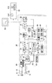
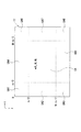
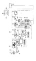
図1は、第1の実施形態である電子内視鏡装置全体のブロック図である。また、図2は、被写体像の表示を示した図である。 FIG. 1 is a block diagram of the entire electronic endoscope apparatus according to the first embodiment. FIG. 2 is a diagram showing display of a subject image.
電子内視鏡装置は、スコープ10とプロセッサ20およびテレビ用モニタ(表示装置)50から構成されており、プロセッサ20にはテレビ用モニタ50が接続されている。スコープ10は、プロセッサ20に着脱自在に接続可能であり、手術や検査などを行う場合、プロセッサ20に接続されて人体の臓器内へ挿入される。なお、電子内視鏡装置全体の動作は、プロセッサ20内のシステムコントロール回路34に設けられたCPU(中央演算処理装置)36により制御されている。
The electronic endoscope apparatus includes a
ハロゲンランプなどの光源29から放射された光は、絞り30および集光レンズ31を介してライトガイド13の入射端13aに入射する。ライトガイド13は、光源29から放射された光をスコープ10の接続端から先端(遠位端)へ導くためのファイババンドル(光束)である。ライトガイド13の入射端13aに入射した光は、ライトガイド13の出射端13bから出射し、配光レンズ14を介してスコープ10の遠位端から出射する。これにより、観察部位Sに光が照射される。なお、スコープ10の接続端は、スコープ10のプロセッサ20との接続側を示す。
Light emitted from a
観察部位Sに光が照射されると、観察部位Sにより反射された光がスコープ10内の対物レンズ11を通る。これによって、被写体像がCCD(撮像素子)12に結像される。被写体像が結像されるCCD12の受光面には、光電変換素子であってCCD12の画素となるフォトダイオード(図示せず)が配列されている。本実施形態では、撮像方式として単板式が適用されており、フォトダイオードの上には、後述する1チップの補色カラーフィルタが配列されている。被写体像がCCD12の受光面に結像されると、光電変換により、補色カラーフィルタを通過する色に応じたアナログの画像信号(電荷)が画素毎に発生する。
When the observation site S is irradiated with light, the light reflected by the observation site S passes through the
図1においてスコープ10内に設けられたCCD12は、約120万の画素数を有するCCDであり、いわゆるメガピクセルCCDである。EEPROM15には、スコープ10の特性(CCD12の画素数など)に関連するデータがあらかじめ記憶されており、電子スコープ10がプロセッサ20に接続されると、電子スコープ10の特性に関するデータが、システムコントロール回路34へ送られる。
In FIG. 1, a
被写体像を動画像としてモニタ50に表示する通常表示状態では、CCD12において発生する画像信号は、以下に述べるように処理される。なお、本実施形態では、カラーテレビジョン方式としてNTSC方式が適用されており、モニタ50の解像度はNTSC方式に従う。
In the normal display state in which the subject image is displayed on the
CCDドライバ16は、CCD12を駆動するための回路であり、CCDドライバ16から出力される駆動信号は、画像変換回路17を介してCCD12へ送られる。後述するように、CCD12がメガピクセルCCDである場合、CCD12の約120万画素のうち約30万画素に発生する画像信号のみが、CCD12から読み出される。すなわち、CCD12における電荷転送用の転送路(図示せず)に対する駆動信号が適宜画素を間引くように制御されることにより、約30万画素から構成される1フレーム分の被写体像に応じた画像信号が、画像変換回路17へ送られる。画像変換回路17では、システムコントロール回路34から送られてくる制御信号に従って、駆動信号がCCD12へ出力される。
The
約30万画素で構成される被写体像に応じた画像信号は、CCD12から読み出されて画像変換回路17に入力された後、プロセッサ20内のCCDプロセス回路21に送られる。本実施形態ではNTSC方式を適用しているため、CCD12において発生した画像信号は、1フレーム毎に1/30秒間隔で読み出される。
An image signal corresponding to a subject image composed of about 300,000 pixels is read from the
CCDプロセス回路21では、CCD12から読み出された画像信号に対してノイズ除去などの処理が施される。さらに、1フレーム分まとまって読み出された画像信号は、3原色である赤色、青色、緑色の各色に応じた画像信号に変換され、各色毎にそれぞれ分離される。各色に応じた画像信号は、A/D変換回路22へ送られると、アナログ信号からデジタル信号に変換される。デジタル化された画像信号は、画像メモリ23において一時的に格納される。
In the
画像メモリ23に格納されたデジタルの画像信号は、画像メモリ23から読み出され、D/A変換器25に送られる。D/A変換器25では、デジタルの画像信号が、アナログ信号に変換されてビデオプロセス回路26へ送られる。ビデオプロセス回路26では、アナログの画像信号が、NTSC(コンポジットビデオ)信号、Y/C分離信号、あるいはアナログのRGBコンポーネント信号などのビデオ信号(映像信号)に変換される。
The digital image signal stored in the
CRTC(CRT Controller)24では、患者の名前などの文字情報やポインタなどの指示マークをモニタ50に表示するため、文字情報やポインタに応じたキャラクタ信号が出力される。そして、ビデオプロセス回路26では、画像メモリ23から出力される画像信号にキャラクタ信号がインターポーズされる。システムコントロール回路34では、キャラクタ信号を発生させるための制御信号がCRTC24へ出力されており、また、文字情報や指示マークが所定の位置に表示されるように、キャラクタ信号の出力タイミングが調整される。
A CRTC (CRT Controller) 24 displays character information such as the name of a patient and an indication mark such as a pointer on the
ビデオプロセス回路26で生成されるビデオ信号は、NTSC方式に従って順次モニタ50へ出力される。これにより、被写体像(通常表示被写体像)が、動画像としてモニタ50の画面の画像領域NAに表示される(図2参照)。このとき表示される被写体像は、NTSC方式として使用可能な画素数である約41万画素のうちの約30万画素が使用されている。なお、以下では、モニタのカラーテレビジョン方式に従うCCD12の使用可能な約41万の画素を有効画素数といい、NTSC方式であれば、約41万画素である。
Video signals generated by the
システムコントロール回路34には、CPU36、ROM37およびRAM38が設けられており、スコープ10内のEEPROM15から読み出されたデータは、一時的にRAM38へ格納される。通常表示において被写体像が表示される画像領域NAは、接続されるスコープ10内のCCD12の画素数に従っており、スコープ10が接続されると、画像領域NAに対応したデータが、位置メモリ35に格納される。
The
キーボード51(入力装置)では、オペレータによって患者情報などのデータが入力される。通常表示状態では、図2に示すように、モニタ50においてポインタPが必要に応じて表示され、ポインタPが指示する画面上での場所(指示位置)を変更するためにポインタPを移動させる操作がキーボード51上で行われる。
On the keyboard 51 (input device), data such as patient information is input by the operator. In the normal display state, as shown in FIG. 2, the pointer P is displayed on the
キーボード51上に設けられた移動キー51Eが操作されると、操作された移動キー51Eに応じた信号が、システムコントロール回路34へ送られる。キーボード51から送られてくる信号は、ポインタPを移動させる位置の情報をもっており、このポインタPの位置情報に基づき、オペレータが意図する位置にポインタPが表示されるように、制御信号がシステムコントロール回路34からCRTC24へ送られる。これにより、ポインタPは、操作された移動キー51Eに従った方向へ移動する。ただし、ポインタPは、画面上において、上下左右方向に移動する。ファンクションキー51Fは、通常表示状態と拡大表示状態を切り替えるためのキーであり、ポインタPが所定の位置に表示された状態でファンクションキー51Fが操作されると、ポインタPが指していた被写体像の一部を拡大した被写体像(拡大表示被写体像)がモニタ50の画像領域MAにおいて表示される(図2参照)。このとき、CCD12では、画像変換回路17からの駆動信号に基づいて、拡大表示状態において表示される被写体像を構成する画素に発生する画像信号のみが読み出される。キーボード51のファンクションキー51Fが再び押されると、通常表示状態に切り替わり、通常表示の被写体像がモニタ50に表示される。
When the movement key 51E provided on the
なお、キーボード51の操作によるポインタPの位置の移動に関しては、従来知られているように、被写体像が表示されている画像領域NA内に常に収まるように(枠から外れないように)ポインタPが移動する。そのため、システムコントロール回路34では、位置メモリ35に格納されている接続されたスコープ10に応じた画像領域NAのデータとキーボード51から送られてくるポインタPの移動に関する信号に基づいて、ポインタPが移動する。
Regarding the movement of the position of the pointer P by the operation of the
タイミングジェネレータ28では、CCDドライバ16、CCDプロセス回路21、A/D変換回路22、画像メモリ23、CRTC24、D/A変換器25、ビデオプロセス回路26に対して、クロックパルスや同期信号などが出力される。これにより、各回路における画像信号の入出力タイミングが調整される。
The
また、CCDプロセス回路21では、CCD12から読み出される画像信号から輝度信号が生成され、A/D変換器22を介してシステムコントロール回路34へ送られる。システムコントロール回路34では、送られてきた輝度信号に基づいて、絞り30を制御するための制御信号が絞り制御回路33へ送られる。そして、モータ32を駆動するための駆動信号が絞り制御回路33からモータ32へ送られると、モータ32が回転し、モータの回転に連動して絞り30が開閉する。絞り30は、観察部位Sに照射される光量が適正になるように開閉する。
In the
図3は、CCD12における画素配列の一部を模式的に示した図である。図3を用いて、通常表示における被写体像をモニタ50に表示するための間引き処理について説明する。ただし、CCD12の画素数は約120万画素とし、画素数を1/4である約30万画素にする間引き処理を示す。
FIG. 3 is a diagram schematically showing a part of the pixel array in the
補色カラーフィルタCCは、シアンCy、マゼンタMg、イエローYeおよびグリーンGの4色のフィルタ要素から構成されるモザイクフィルタであり、各色がそれぞれ要素となる画素ブロックBが繰り返し配列されることによって構成される。補色フィルタCCの配列は、CCD12上に画素配列、すなわちフォトダイオードの配列に対応している。なお、本実施形態では、電荷転送方式としてインタライン転送方式が適用されており、CCD12の垂直方向には、垂直転送部(図示せず)がフォトダイオードの各列の間に設けられ、また、フォトダイオード配列の下部には、垂直転送部に転送された電荷が転送される水平転送部(図示せず)が設けられている。また、図3では、補色カラーフィルタCCの配列が画素配列の上に設けられている状態が示されている。
The complementary color filter CC is a mosaic filter composed of four color filter elements of cyan Cy, magenta Mg, yellow Ye, and green G, and is configured by repeatedly arranging pixel blocks B each of which is an element. The The arrangement of the complementary color filters CC corresponds to the pixel arrangement on the
約120万画素の中から約30万画素を間引くことから、隣接する4つの同色のフィルタ要素の位置にある4つの画素の中から1つの画素だけを選び出し、その画素に蓄積される電荷のみを垂直転送路へ転送する。選ばれなかった残りの3つの画素に関しては、蓄積される電荷を転送しない。このような4つの画素の中から1つの画素を抽出する処理を補色フィルタCCの要素毎に対してくり返し実行する。 Since about 300,000 pixels are thinned out from about 1,200,000 pixels, only one pixel is selected from the four pixels at the positions of four adjacent filter elements of the same color, and only the charge accumulated in that pixel is selected. Transfer to the vertical transfer path. For the remaining three pixels not selected, the accumulated charge is not transferred. Such a process of extracting one pixel from the four pixels is repeatedly executed for each element of the complementary color filter CC.
図3に示す画素配列の各画素をPjiと示し、間引き処理によって選び出される各画素をP’jiとすると、画素P’jiは、次に示す4つの式(1)〜(4))のいずれかの式によって求められる。ただし、添字j(0〜7)は、画素Pji、P’jiの垂直方向の位置を示し、添字i(0〜7)は、画素Pji、P’jiの水平方向の位置を示す。 If each pixel of the pixel array shown in FIG. 3 is denoted by P ji and each pixel selected by the thinning process is denoted by P ′ ji , the pixel P ′ ji is represented by the following four expressions (1) to (4)): It is calculated | required by either formula. Note that the subscript j (0 to 7) indicates the vertical position of the pixels P ji and P ′ ji , and the subscript i (0 to 7) indicates the horizontal position of the pixels P ji and P ′ ji .
P’ji=Pji (j<2,i<2) ・・・(1)
P’ji=Pj+2,i (j≧2,i<2) ・・・(2)
P’ji=Pj,i+2 (j<2,i≧2) ・・・(3)
P’ji=Pj+2,i+2 (j≧2,i≧2) ・・・(4)
P ′ ji = P ji (j <2, i <2) (1)
P ′ ji = P j + 2, i (j ≧ 2, i <2) (2)
P ′ ji = P j, i + 2 (j <2, i ≧ 2) (3)
P ′ ji = P j + 2, i + 2 (j ≧ 2, i ≧ 2) (4)
例えば、隣接する4つの同色フィルタ要素であるシアンCy11、Cy12、Cy21、Cy22の位置にある画素P00、P02、P20、P22の中から、シアンCy11に応じた画素P00が(1)式により画素P’00として抽出される。同じように、隣接する4つのフィルタ要素であるイエローY33、Ye34、Ye43、Ye44の位置にある画素P54、P56、P74、P76の中から、イエローYe33に応じた画素P54が(4)式により画素P’32として抽出される。 For example, a pixel corresponding to cyan Cy 11 is selected from the pixels P 00 , P 02 , P 20 , and P 22 at the positions of cyan Cy 11 , Cy 12 , Cy 21 , and Cy 22 that are adjacent four same color filter elements. P 00 is extracted as a pixel P ′ 00 by the expression (1). Similarly, according to the yellow Ye 33 among the pixels P 54 , P 56 , P 74 , and P 76 at the positions of yellow Y 33 , Ye 34 , Ye 43 , and Ye 44 that are adjacent four filter elements. Pixel P 54 is extracted as pixel P ′ 32 by equation (4).
このような間引き処理を、CCD12に形成される、すなわち約120万の全画素数で構成される被写体像(全画素被写体像)に対して施すことにより、1/4の画素数となる約30万画素で構成されるとともに、解像度が変換された被写体像が形成される。CCD12における画素配列において、水平方向の画素数をM、垂直方向の画素数をNとし、解像度が変換された被写体像において、水平方向の画素数をm、垂直方向の画素数をnとすると、m=M/2、n=N/2となる。
By performing such a thinning process on the subject image (all-pixel subject image) formed on the
なお、図3では、メガピクセルCCDとしてCCD12の画素数を約120万画素とし、間引き処理後の被写体像を構成する画素数を約30万画素としているが、様々な画素数のメガピクセルCCDを有する電子スコープ10に対しても有効画素数以下の画素数で画像を構成することが可能である。CCD12の画素数がUであり、通常表示における被写体像を構成する画素数をDとした場合、全画素で構成される画像をD/U倍の縮小率となる画像に変換すればよい。このとき、(1)〜(4)式は、縮小率および補色カラーフィルタのフィルタ要素の配列によって変わる。なお、任意の整数倍および有理数倍の間引き処理は、従来公知である。
In FIG. 3, the number of pixels of the
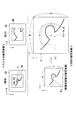
図4は、本実施形態における拡大表示処理を示した図である。図4を用いて、拡大表示処理について説明する。ここでは、モニタ50に表示されるポインタPが指示する位置を画面上の座標で表しており、水平方向の座標をX、垂直方向の座標をYとする。なお、通常、ポインタPの矢印先端が指示する座標が、ポインタPの位置座標であり、システムコントロール回路34では、移動キー51Eから送られてくるポインタPの移動させる位置情報に従ってポインタPの指示する位置を検出する。
FIG. 4 is a diagram showing an enlarged display process in the present embodiment. The enlarged display process will be described with reference to FIG. Here, the position indicated by the pointer P displayed on the
通常表示において、被写体像は画像領域NAに表示されており、被写体像の注目部位にポインタPが移動される。ポインタPの指示する位置が座標(X0、Y0)である時にオペレータがファンクションキー51Fを操作すると、以下に示すような処理が施される。
In the normal display, the subject image is displayed in the image area NA, and the pointer P is moved to the target part of the subject image. If the operator operates the
まず、ポインタPによって指示される座標(X0、Y0)に基づき、約30万画素で構成される通常表示の被写体像の中で、ポインタPの示した場所に対応する画素P’Cが求められる。 First, based on the coordinates (X0, Y0) indicated by the pointer P, a pixel P ′ C corresponding to the location indicated by the pointer P is obtained from the normal display subject image composed of about 300,000 pixels. .
ところで、間引き処理によって形成される通常表示の被写体像は、CCD12の約120万の全画素数からなる画像形成領域(画像領域)に形成される被写体像(全画素被写体像)に基づく。また、図3に示したように、間引き処理では、CCD12の画素配列の中のいずれかの画素Pjiが、そのまま解像度の変換された通常表示の被写体像を構成する画素P’jiとなる。したがって、(1)〜(4)式のいずれかの式により、CCD12の画素配列において、画素P’Cに対応する画素PC(指示画素)が求められる。ここでは、図4に示すように、CCD12の画素が配列された領域、すなわち、被写体像が形成される領域を画像形成領域TIとし、画像形成領域TIにおける画素PCの座標を(K、H)と表す。
By the way, the normal display subject image formed by the thinning-out processing is based on the subject image (all-pixel subject image) formed in the image forming region (image region) having the total number of pixels of about 1,200,000 of the
画面上においてポインタPの指示した位置を中心として通常表示における被写体像の一部を拡大表示するため、画素PCを中心として部分領域PIを定める。ただし、部分領域PIは、画像形成領域TIの中の一部領域である。そして、この部分領域PI内に位置するすべての画素によって構成される像を拡大表示の被写体像(拡大表示被写体像)とする。 To enlarge a portion of the subject image in the normal display around the indicated position of the pointer P on the screen to define a partial region PI around the pixel P C. However, the partial area PI is a partial area in the image forming area TI. An image constituted by all the pixels located in the partial area PI is set as an enlarged display subject image (enlarged display subject image).
本実施形態では、モニタ50の画面において、通常表示状態における領域NAと拡大表示における領域MAのサイズは等しい。すなわち、拡大表示の被写体像の画素数は、通常表示の被写体像の画素数と同じ約30万画素で構成される。したがって、拡大表示の被写体像を形成するため、画素PCを中心として約30万の画素によって構成される部分領域PIが定められる。このときの部分領域PI内の画素数は、水平方向にm(=M/2)個、垂直方向にn(=N/2)個となる。
In the present embodiment, the size of the area NA in the normal display state and the area MA in the enlarged display on the screen of the
そして、上述したように、部分領域PI内にある画素に発生する画像信号がCCD12から読み出されることにより、拡大表示の被写体像がモニタ50の領域MAに表示される。なお、本実施形態における拡大率は、4倍である。
Then, as described above, the image signal generated in the pixels in the partial area PI is read from the
図5は、画像形成領域TIにおける画素Pcの位置を示した図である。図5を用いて、画素Pcの位置について説明する。 FIG. 5 is a diagram showing the position of the pixel Pc in the image forming area TI. The position of the pixel Pc will be described with reference to FIG.
上述したように、部分領域PIには、画素PCを中心として、水平方向にm個、垂直方向にn個の画素がある。すなわち、水平方向に関しては、指定画素PCから負の方向(左方向)および正の方向(右方向)にそれぞれm/2個の画素があることが、また、垂直方向に関しては、画素PCから負の方向(上方向)および正の方向(下方向)にそれぞれn/2個の画素があることが必要である。したがって、CCD12の画像形成領域TIの中で、画素PCの位置が画像形成領域TIの外周付近である場合、m×n個の画素数(所定画素数)で拡大表示の被写体像を構成することができない。
As described above, the partial area PI, around the pixel P C, there are n pixels in the horizontal direction of m, the vertical direction. That is, regarding the horizontal direction, there are m / 2 pixels in the negative direction (left direction) and the positive direction (right direction) from the designated pixel P C, and regarding the vertical direction, the pixel P C is present. It is necessary that there are n / 2 pixels in the negative direction (upward direction) and the positive direction (downward direction). Accordingly, when the position of the pixel P C is in the vicinity of the outer periphery of the image forming area TI in the image forming area TI of the
例えば、図5で示すように、指定画素PC(K、H)の位置が、座標(m/2,n/2)の位置よりも原点(0、0)に近い場合、斜線で示す領域がCCD12の画像形成領域TI外に出てしまい、m×n個の画素で拡大表示の被写体像を構成することができない。
For example, as shown in FIG. 5, when the position of the designated pixel P C (K, H) is closer to the origin (0, 0) than the position of the coordinates (m / 2, n / 2), the area indicated by hatching Is out of the image forming area TI of the
そのため、本実施形態では、拡大処理を実行する場合、後述するように、CCD12の画像形成領域TIを9つの領域に分け、それぞれの領域に従って、拡大表示被写体像の画像領域PIを定める。
Therefore, in this embodiment, when executing the enlargement process, as will be described later, the image forming area TI of the
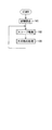
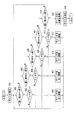
図6は、システムコントロール回路34内のCPU36によって実行される内視鏡装置全体の動作を示すフローチャートである。
FIG. 6 is a flowchart showing the entire operation of the endoscope apparatus executed by the
ステップ101では、電源がON状態になることによって、絞り30や光源29などに関する設定値がそれぞれ初期値に設定される。ステップ102では、スコープ10に関連する処理が施される。ステップ103では、例えば、日付の表示処理などが施される。このような内視鏡装置全体の動作は、電源がOFFになるまで繰り返し行われ、ステップ102〜103における各ステップでは、サブルーチンが実行される。
In step 101, when the power is turned on, the set values relating to the
図7は、図6のステップ102のサブルーチンを示した図である。 FIG. 7 is a diagram showing a subroutine of step 102 in FIG.
ステップ201では、スコープ10の交換がなされたか否かが判定される。すなわち、今まで接続されていたスコープ10が取り外されて別のスコープ10が新たにプロセッサ20に接続されたか否かを判別する。新たにスコープ10がプロセッサ20に接続されたと判断されると、ステップ202に進む。新たにスコープ10がプロセッサ20に接続されてはいないと判断されると、このサブルーチンは終了し、ステップ102に戻る。なお、図6のステップ101が実行された後始めてステップ201に進む場合(電源がON状態になってからはじめてステップ201に進む場合)、ステップ202に進む。ステップ202では、プロセッサ20に接続されたスコープ10のEEPROM15から読み出されたCCD12の画素数に関するデータに基づいて、CCD12の画素数が有効画素数より多いか否かが判定される。
In
ステップ202において、CCD12の画素数が有効画素数よりも多いと判断された場合、ステップ203に進み、間引き処理が施される。すなわち、約30万画素によって構成される通常表示の被写体像に応じた画像信号がCCD12から読み出される。そして、ステップ204では、画像信号に基づいて生成されたビデオ信号がビデオプロセス回路26からモニタ50へ出力され、これにより、通常表示の被写体像がモニタ50に表示される。ステップ204が実行されると、サブルーチンは終了する。
If it is determined in
一方、ステップ202においてCCD12の画素数が有効画素数よりも多くないと判断された場合、ステップ205に進む。ステップ205では、CCD12の画素数が有効画素数以下であるため、CCD12の全画素数で構成される被写体像に応じた画像信号がCCD12から読み出される。ステップ206では、有効画素数以下であるCCD12の全画素で構成される被写体像に応じたビデオ信号がモニタ50に出力され、これにより、通常表示における被写体像がモニタ50に表示される。
On the other hand, if it is determined in
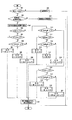
図8は、拡大表示処理を示した割り込みルーチンである。また、図9は、撮像素子12における画像形成領域TIを示した図である。キーボード51のファンクションキー51Fが操作されると、割り込み処理が開始される。
FIG. 8 is an interrupt routine showing the enlarged display process. FIG. 9 is a diagram showing an image forming area TI in the
ステップ301では、キーボード51のファンクションキー51Fに対する操作が、通常表示から拡大表示へ切り替える操作であるか否かが判定される。
In
ステップ301において、通常表示から拡大表示へ切り替える操作であると判断されると、ステップ302へ進む。ステップ302では、プロセッサ20に接続されているスコープ10内のCCD12の画素数が、有効画素数以上であるか否かが判定される。
If it is determined in
ステップ302において、撮像素子12の画素数が有効画素数以上であると判断されると、ステップ303へ進む。ステップ303では、ポインタPのモニタ50の画面上における指示位置の座標(X0,Y0)が検出される。そして、図4に示したように、その指示位置の座標(X0、Y0)に基づいて、画像形成領域TIにおいて対応する画素PC(K、H)が求められる。
If it is determined in
ステップ304では、画素PC (K、H)のうち、i方向の座標Kについて、次式が満たされるか否か判断される。ただし、mは、拡大表示被写体像および通常表示被写体像を構成する水平方向の画素数である。
0≦K<m/2 ・・・・・・(5)
In
0 ≦ K <m / 2 (5)
図9に示すように、CCD12の画像形成領域TIを9つの領域UA1〜UA8およびCAに分ける。画素PCが領域CA内に位置する場合には、そのまま指定画素PC を中心としてm×n個の画素からなる部分領域PIを定める。一方、指定画素PC がそれ以外の領域UA1〜UA8に位置する場合、指示画素PC は領域CAの周上にある修正画素P’Cに変換され、この修正画素P’C を中心として、m×n個の画素からなる部分領域PIを定める。(5)式では、画素PC が、領域UA1、UA2、UA3内に位置しているか否かが判定される。
As shown in FIG. 9, the image forming area TI of the
ステップ304において、(5)式が満たされる、すなわち、画素PC が領域UA1、UA2、UA3のいずれかの領域内に位置すると判断されると、ステップ305に移る。ステップ305では、画素PC(K、H)のうち、j方向の座標Hについて、次式が満たされるか否かが判定される。
0≦H<n/2 ・・・・・・(6)
すなわち、画素PCが、領域UA1内に位置しているか否かが判定される。
If it is determined in
0 ≦ H <n / 2 (6)
That is, the pixel P C is, whether located within the region UA1 is determined.
ステップ305において、(6)式が満たされていると判断されると、ステップ307に移る。画素PCがこのままの位置であれば画素数m×n個で部分領域PIを定めることが出来ないため、ステップ307では、画素Pcが、(m/2、n/2)の位置の画素Pm/2,n/2に変換される。ステップ307が実行されると、ステップ320へ進む。
If it is determined in step 305 that the expression (6) is satisfied, the process proceeds to step 307. If the pixel P C remains in this position, the partial area PI cannot be determined with the number of pixels m × n. Therefore, in
一方、ステップ305において、(6)式が満たされていないと判断されると、ステップ306に移る。ステップ306では、画素PC(K、H)のうち、j方向の座標Hについて、次式が満たされるか否かが判定される。
n/2≦H≦N−n/2 ・・・・・・・(7)
すなわち、画素PCが領域UA2内に位置するか否かが判定される。
On the other hand, if it is determined in step 305 that the expression (6) is not satisfied, the process proceeds to step 306. In
n / 2 ≦ H ≦ N−n / 2 (7)
That is, the pixel P C whether located within the region UA2 is determined.
ステップ306において、(7)式が満たされると判断されると、ステップ308に移る。画素PCがこのままの位置であれば画素数m×n個で部分領域PIを定めることが出来ないため、ステップ308では、画素PCが、(m/2、H)の位置にある画素Pm/2,H へ変換される。すなわち、画素PCは、領域UA2と領域CAの境界線上にある画素に変換される。一方、ステップ306において、(7)式が満たされていない、すなわち、画素PCが領域UA3内に位置すると判断されると、ステップ309に移る。画素PCがこのままの位置であれば画素数m×n個で部分領域PIを定めることが出来ないため、ステップ309では、画素PCが(m/2、N−n/2)の位置にある画素Pm/2,N-n/2 へ変換される。ステップ308、ステップ309が実行されると、それぞれステップ321へ進む。
If it is determined in
一方、ステップ304において、(7)式を満たさない、すなわち、画素PCが領域UA1、UA2、UA3のいずれにも位置していないと判断されると、ステップ310へ進む。ステップ310では、画素PC(K、H)のうち、i方向の座標Kについて(8)式が満たされるか否かが判定される。
m/2≦K≦M−m/2 ・・・・・・(8)
すなわち、画素PCが、領域UA4、UA5およびCAのいずれかに位置しているか否かが判定される。
On the other hand, in
m / 2 ≦ K ≦ M−m / 2 (8)
That is, the pixel P C is, whether located in any area UA4, UA5 and CA is determined.
ステップ310において、(8)式が満たされると判断されると、ステップ311へ移る。ステップ311では、画素PC(K、H)のうち、j方向の座標Hについて(9)式が満たされるか否かが判定される。
0≦H≦n/2 ・・・・・・・(9)
すなわち、画素PC が、領域UA4内に位置するか否かが判定される。(9)式が満たされると判断されると、ステップ313へ移る。画素PCがこのままの位置であれば画素数m×n個で部分領域PIを定めることが出来ないため、ステップ313では、画素PCが、(K、n/2)の位置にある画素PK、n/2へ変換される。すなわち、画素PCが領域CAと領域UA4との境界線上にある画素に変換される。ステップ313が実行されると、ステップ321へ移る。一方、ステップ311において(9)式が満たされないと判断されると、ステップ312へ進む。
If it is determined in
0 ≦ H ≦ n / 2 (9)
That is, the pixel P C is, whether located within the region UA4 is determined. If it is determined that the expression (9) is satisfied, the process proceeds to step 313. If the pixel P C remains in this position, the partial area PI cannot be determined with the number of pixels of m × n. Therefore, in
ステップ312では、画素PC(K、H)のうち、j方向の座標Hについて(10)式が満たされるか否かが判定される。
n/2≦H≦N−n/2 ・・・・・・・・(10)
すなわち、画素PCが、領域CA内に位置するか否かが判定される。
In
n / 2 ≦ H ≦ N−n / 2 (10)
That is, the pixel P C is, whether located within the area CA is determined.
ステップ312において、(10)式が満たされると判断されると、ステップ314へ移る。ステップ314では、画素PCが変換されることなく、そのまま画素PC(K、H)が拡大表示被写体像の中心に定められる。一方、ステップ312において、(10)式が満たされないと判断される、すなわち、画素PCが領域UA5内に位置すると判断されると、ステップ315へ進む。画素PCがこのままの位置であれば画素数m×n個で部分領域PIを定めることが出来ないため、ステップ315では、画素PCが、(K、N−n/2)の位置にある画素PK,N-n/2へ変換される。すなわち、画素PCが領域CAと領域UA5との境界線上にある画素に変換される。ステップ314、315が実行されると、それぞれステップ321へ進む。
If it is determined in
一方、ステップ310において、(10)式が満たされない、すなわち画素PCが領域UA6、UA7、UA8のいずれかの領域に位置すると判断されると、ステップ316へ移る。ステップ316では、画素PC(K、H)のうち、j方向の座標Hについて(11)式が満たされるか否かが判定される。
0≦H≦n/2 ・・・・・・・・・(11)
すなわち、画素PCが、領域UA6内に位置するか否かが判定される。ステップ316において、(11)式が満たされると判断されると、ステップ318へ移る。ステップ318では、画素PCが(M−m/2,n/2)の位置にある画素PM-m/2,n/2へ変換される。ステップ318が実行されると、ステップ321へ進む。一方、ステップ316において、(11)式が満たされないと判断されると、ステップ317へ進む。
On the other hand, in
0 ≦ H ≦ n / 2 (11)
That is, the pixel P C is, whether located within the region UA6 is determined. If it is determined in
ステップ317では、画素PC(K、H)のうち、j方向の座標Hについて(12)式が満たされるか否かが判定される。
n/2≦H≦N−n/2 ・・・・・・・(12)
すなわち、画素PCが、領域UA7に位置するか否かが判定される。
In
n / 2 ≦ H ≦ N−n / 2 (12)
That is, the pixel P C is, whether positioned in the region UA7 is determined.
ステップ317において(12)式が満たされると判断されると、ステップ319へ移る。ステップ319では、画素PCが(M−m/2、H)の位置にある画素PM-m/2,Hへ変換される。すなわち、画素PCが領域CAと領域UA7との境界線上にある画素に変換される。一方、ステップ317において、(12)式が満たされない、すなわち画素PCが領域UA8内に位置すると判断されると、ステップ320へ進む。ステップ320では、画素PCが(M−m/2、N−n/2)の位置にある画素PM-m/2,N-n/2へ変換される。ステップ319、320が実行されると、それぞれステップ321へ進む。
If it is determined in
ステップ321では、ステップ314において定められた画素PC、およびステップ307〜309、313、315、318〜320において求められた変換画素の位置を中心とした部分領域PI内にある画素に発生する画像信号が、CCD12から読み出される。そして、読み出された画像信号に基づいて、拡大表示の被写体像がモニタ50に表示される。ステップ321が実行されると、このルーチンは終了する。
In
一方、ステップ302において、CCD12の画素数が有効画素数以上ではないと判断されると、ステップ322へ進む。ステップ322では、CCD12の全画素に応じた画像信号が読み出され、画像メモリ23において補間処理が施される。これにより、補間処理の施された拡大表示の被写体像がモニタ50に表示される。ステップ322が実行されると、このルーチンは終了する。
On the other hand, if it is determined in
ステップ301において、通常表示から拡大表示へ切り替える操作でなく、拡大表示から通常表示へ切り替える操作であると判断された場合、ステップ323に進み、通常表示の被写体像がモニタ50に表示される。ステップ323が実行されると、このルーチンは終了する。
If it is determined in
図10は、ステップ323のサブルーチンである。
FIG. 10 is a subroutine of
ステップ351〜355の実行は、図7のステップ202〜206の実行と同じである。すなわち、撮像素子12の画素数が有効画素数以上であるか否かが判断され、有効画素数以上の画素数であれば間引き処理が施され、解像度の変換された被写体像がモニタ50に表示される。一方、有効画素数以下の画素数であれば、そのまま全画素に応じた画像信号が撮像素子12から読み出され、解像度変換されることなく被写体像がモニタ50に表示される。
The execution of
このように第1の実施形態によれば、通常表示状態においては、有効画素数以下の画素数(約30万画素)で構成される被写体像がモニタ50に表示され、拡大表示状態においては、CCD12の画像形成領域TIの中の部分領域PI内にある画素によって構成される被写体像がモニタ50に表示される。拡大表示処理において補間処理をする必要がないため、通常表示の被写体像の患部を拡大して観察する場合、解像度が低下することなく患部が拡大された映像が表示され、これにより、患部の状態を正確に診断することができる。また、CCD12がメガピクセルである場合、通常表示状態においても、モニタ50の有効画素数に近い画素数で被写体像をモニタ50に表示することができる。
As described above, according to the first embodiment, in the normal display state, a subject image composed of the number of pixels equal to or less than the effective number of pixels (approximately 300,000 pixels) is displayed on the
スコープ10内のCCD12の画素数が有効画素数以下である場合、通常表示状態では、解像度を変換せずにCCD12の全画素によって構成される被写体像がモニタ50に表示される。これにより、CCD12の画素数が少ない場合には、従来と同じように通常表示、拡大表示の映像が映し出され、通常表示において解像度が著しく低下した被写体像が表示されることがない。すなわち、メガピクセルCCDを有するスコープとともに、従来の画素数が少ないスコープにも対応している。
When the number of pixels of the
画像変換回路17がスコープ10内に設けられているため、従来のプロセッサの回路構成をほとんど変更しないでこのスコープに対応したプロセッサ20を製造することが可能である。
Since the
本実施形態では、通常表示において、約30万画素で構成される被写体像を表示するが、有効画素数以下の画素数であれば、これ以外の画素数、例えば、有効画素数と略等しい約41万画素で被写体像を構成してもよい。同じように、拡大表示においても、約30万の画素数で被写体像を構成することに限定されず、有効画素数以下の画素数で被写体像を構成すればよい。 In the present embodiment, a subject image composed of about 300,000 pixels is displayed in normal display. However, if the number of pixels is equal to or less than the number of effective pixels, the number of pixels other than this, for example, approximately the same as the number of effective pixels. The subject image may be composed of 410,000 pixels. Similarly, in the enlarged display, the subject image is not limited to the number of pixels of about 300,000, and the subject image may be configured with the number of pixels equal to or less than the number of effective pixels.
通常表示においては、全画素によって構成される被写体像に対する間引き処理により、解像度が変換された被写体像を形成しているが、それ以外の処理によって解像度変換の被写体像を形成してもよい。この場合、(1)〜(4)式に代わる解像度変換の被写体像とCCD12に形成される被写体像との画素の関係式が定められる。
In normal display, a subject image whose resolution is converted is formed by thinning out a subject image composed of all pixels, but a subject image whose resolution is converted may be formed by other processing. In this case, a relational expression of pixels between the subject image for resolution conversion and the subject image formed on the
第1の実施形態では、通常表示および拡大表示において被写体像を構成する画素に発生する画像信号のみ、CCD12から画像変換回路17へ出力される構成であるが、CCD12の全画素の画像信号を読み出し、画像変換回路17において被写体像を構成する画素に応じた画像信号だけをプロセッサ20へ送る構成にしてもよい。あるいは、プロセッサ20内、例えば、画像メモリ23とD/A変換器25との間に画像変換回路17を設けてもよい。
In the first embodiment, only the image signal generated in the pixels constituting the subject image in the normal display and the enlarged display is output from the
次に、図11を用いて、第2の実施形態である電子内視鏡装置およびそのシステムについて説明する。第2の実施形態は、第1の実施形態と異なり、オペレータがモニタ50の画面に配置されたタッチパネルを操作することによって、拡大表示処理が実行される。その他については、第1の実施形態と同じであり、同じ参照符号は同じ構成要素を示す。
Next, an electronic endoscope apparatus and system thereof according to the second embodiment will be described with reference to FIG. Unlike the first embodiment, the second embodiment performs an enlarged display process by an operator operating a touch panel arranged on the screen of the
モニタ50の画面上には、無色透明のマトリクス状の電極を配設したタッチパネルTPが配置されており、観察部位Sの画像は、タッチパネルTPを通して観察される。タッチパネルTPは、画面上の位置情報をプロセッサ20へ送る装置であり、オペレータがタッチパネルTPを指で触れると、指によって触れられた場所に応じた画面上の位置に関する信号が、インターフェイス(図示せず)を介してシステムコントロール回路34へ入力される。そして、プロセッサでは、指によって触れられた場所に応じた画面上の位置(指示位置)が検出される。ただし、ここでは、指示された画面上の場所を検出する方式として、赤外線方式が適用されている。
On the screen of the
位置メモリ35には、第1の実施形態と同じように、スコープ10内のCCD12の画素数に従った被写体像の表示領域がデータとして格納されており、オペレータによって指示された画面上の位置がその表示領域(図2の領域NA)内にあるか判断される。表示領域内にある場合、第1の実施形態と同じように、拡大表示処理が施される。一方、表示領域以外の部分をオペレータが指で指示した場合、拡大表示処理は実行されない。拡大表示の被写体像がモニタ50に表示されている状態でタッチパネルTP上の所定の場所がオペレータによって触れられると、拡大表示から通常表示へ切り替わる。
As in the first embodiment, the
このように第2の実施形態によれば、タッチパネルTPが操作されることにより、通常表示の被写体像は、拡大表示の被写体像へ切り替えられる。 As described above, according to the second embodiment, when the touch panel TP is operated, the normal display subject image is switched to the enlarged display subject image.
図12を用いて、第3の実施形態について説明する。第3の実施形態は、第1の実施形態と異なり、スコープに設けられた操作ボタンを操作することにより、モニタ上のポインタの位置を移動させる。その他の構成に関しては、第1の実施形態と同じである。 A third embodiment will be described with reference to FIG. Unlike the first embodiment, the third embodiment moves the position of the pointer on the monitor by operating an operation button provided on the scope. Other configurations are the same as those in the first embodiment.
スコープ10には、プッシュボタンである第1指示マークプッシュボタン18A、第2指示マークプッシュボタン18B、第3指示マークプッシュボタン18Cが設けられている。第1〜第3指示マークプッシュボタン18A〜18Cは、モニタ50の画面上でのポインタPの位置を移動させるための位置情報入力装置であり、画面上においてポインタPを上下左右方向へ移動させる。オペレータによって第1〜第3指示マークプッシュボタン18A〜18Cが操作されると、ポインタPの移動する位置に関する情報が、システムコントロール回路34へ送られる。
The
システムコントロール回路34では、モニタ50上のポインタPの位置を変更するため、第1〜第3指示マークプッシュボタン18A〜18Cから送られてくる信号に基づいて制御信号がCRTC24へ送られる。CRTC24では、送られてきた制御信号に基づいて、ポインタPに応じたキャラクタ信号の出力タイミングが調整される。
In the
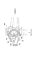
図13は、スコープ10の一部を示した図である。
FIG. 13 is a view showing a part of the
図13に示すように、スコープ10のプロセッサ側には、オペレータが操作する様々な操作器具を備えた操作部10Mが設けられており、オペレータは、処置をする時には、スコープ10の先端部(図示せず)を湾曲させるためのレバーLEを右手で操作する。操作部10Mには、凸型であって「くの字」型の形状である端部10Kが形成されている。処置等をするためオペレータがスコープ10を保持している間、端部10Kの両側に相対するように位置する2つの表面部分のうち、第1の表面10R1は上方向を向き、他方の第2の表面10R2は下方向を向いている。
As shown in FIG. 13, on the processor side of the
第1指示マークプッシュボタン18Aは、端部10Kにおいて、第2の表面10R2上に設けられており、オペレータの親指で操作できるように配置されている。一方、第2、第3指示マークプッシュボタン18B、18Cは、オペレータの人差指、中指で操作できるように、第1の表面10R1に配置されている。第1指示マークプッシュボタン18Aは、端部10Kにおいて、第2、第3指示マークプッシュボタン18B、18Cと向かい合うように配置されており、オペレータは、左手の親指で第1指示マークプッシュボタンを押しながら第2、第3指示マークプッシュボタン18B、18Cを左手の人差指、中指で操作することが可能である。
The first instruction
図14は、第1〜第3指示マークプッシュボタン18A〜18Cに対するポインタの表示位置移動処理を示した割り込みルーチンである。
FIG. 14 is an interrupt routine showing pointer display position movement processing for the first to third instruction
第1指示マークプッシュボタン18Aは、ポインタPが表示されていない状態からポインタPを表示する状態へ切り替えるためのスイッチを兼用しており、ポインタPがモニタ50に表示されない状態で第1指示マークボタン18Aが操作されると、この割り込みルーチンは開始される。
The first instruction
ステップ401では、ポインタPが画面に表示されるように、システムコントロール回路34からCRTC24へ制御信号が送られる。そして、ステップ402では、第1、第2指示マークプッシュボタン18A、18Bがオペレータによって同時に操作されたか否かが判定される。ただし、本実施形態では、ポインタPを右方向へ1座標分移動させる場合、第1、第2指示マークプッシュボタン18A、18Bが同時に押下される。
In
ステップ402において、第1、第2指示マークプッシュボタン18A、18Bが同時に操作されたと判断されると、ステップ403に移る。ステップ403では、通常表示において、ポインタPが、現在、領域MA(図2参照)内に位置するか否かが判定される。ポインタPが領域MA内に位置する、すなわち領域MAの右側の境界線上に位置せず、一座標分ポインタPを右側へ移動可能であると判断されると、ステップ404に移り、ポインタPが1座標分だけ右方向へ移動される。一方、ステップ403においてポインタPが領域MAの右側の境界線上に位置していると判断されると、領域MA内にポインタPを表示するため、ポインタPの移動は実行されず、ステップ402へ戻る。
If it is determined in
ステップ402において、第1、第2指示マークプッシュボタン18A、18Bが同時に操作されてはいないと判断された場合、ステップ405に移る。ステップ405では、第1、第3指示マークプッシュボタン18A、18Cが同時に操作されたか否かが判定される。ただし、本実施形態では、ポインタPを左方向へ1座標分移動させる場合、第1、第3指示マークプッシュボタン18A、18Cが同時に押下される。
If it is determined in
ステップ405において、第1、第3指示マークプッシュボタン18A、18Cが同時に操作されたと判断されると、ステップ406に移る。ステップ406では、ポインタPが、現在、領域MA内に位置するか否かが判定される。ポインタPが領域MA内に位置する、すなわち領域MAの左側の境界線上に位置せず、一座標分ポインタPを左側へ移動可能であると判断されると、ステップ407に移り、ポインタP1座標分だけ左方向へ移動される。一方、ステップ406においてポインタPが領域MAの左側の境界線上に位置していると判断されると、領域MA内にポインタPを表示するため、ポインタPの移動は実行されず、ステップ402へ戻る。
If it is determined in
一方、ステップ405において第1、第3指示マークプッシュボタン18A、18Cが同時に操作されてはいないと判断された場合、ステップ408に移る。ステップ408では、第2指示マークプッシュボタン18Bが操作されたか否かが判定される。ただし、第2指示マークプッシュボタン18Bの操作は、ポインタPを1座標分だけ下方向へ移動させるための操作である。
On the other hand, if it is determined in
ステップ408において、第2指示マークプッシュボタン18Bが操作されたと判断されると、ステップ409に移る。ステップ409では、ポインタPが、現在、領域MA内に位置するか否かが判定される。ポインタPが領域MA内に位置する、すなわち領域MAの下側の境界線上に位置せず、一座標分ポインタPを下側へ移動可能であると判断されると、ステップ410に移り、ポインタPが1座標分だけ下方向へ移動される。一方、ステップ409においてポインタPが領域MAの下側の境界線上に位置していると判断されると、領域MA内にポインタPを表示するため、ポインタPの移動は実行されず、ステップ402へ戻る。
If it is determined in
一方、ステップ408において、第2指示マークプッシュボタン18Bが操作されていないと判断されると、ステップ411に移る。ステップ411では、第3指示マークプッシュボタン18Cが操作されたか否かが判定される。第3指示マークプッシュボタン18Cの操作は、ポインタPを1座標分だけ上方向へ移動させるための操作である。
On the other hand, if it is determined in
ステップ411において、第3指示マークプッシュボタン18Cが操作されたと判断されると、ステップ412へ移る。ステップ412では、ポインタPが、現在、領域MA内に位置するか否かが判定される。ポインタPが領域MA内に位置する、すなわち領域MAの上側の境界線上に位置せず、一座標分ポインタPを上側へ移動可能であると判断されると、ステップ413に移り、ポインタPが1座標分だけ上へ移動される。一方、ポインタPが領域MAの上側の境界線上に位置していると判断されると、領域MA内にポインタPを表示するため、ポインタPの移動は実行されず、ステップ402へ戻る。
If it is determined in
一方、ステップ411において、第3指示マークプッシュボタン18Cが操作されていないと判断されると、ステップ414に移る。ステップ414では、第2、第3指示マークプッシュボタン18B、18Cが同時に操作されたか否かが判定される。ただし、第2、第3指示マークプッシュボタン18B、18Cの同時操作は、拡大表示処理を実行するための操作である。
On the other hand, if it is determined in
ステップ414において、第2、第3指示マークプッシュボタン18B、18Cが同時に操作されたと判断されると、ステップ415に移り、ポインタPの位置がシステムコントロール回路34において求められる。そして、ステップ416では、拡大表示処理によって拡大表示の被写体像を表示するため、ポインタPが画面から消去される。ステップ416が実行されると、このルーチンは終了する。一方、ステップ414において、第2、第3指示マークプッシュボタン18B、18Cが同時に操作されてはいないと判断されると、ステップ402に戻る。
If it is determined in
このように第3の実施形態によれば、第1、第2、第3指示マークプッシュボタン18A、18B、18Cの操作により、通常表示において、ポインタPが領域MA内において移動される。第1〜第3指示マークプッシュボタン18A〜18Cがスコープ10の端部10Kに設けられているため、オペレータは、スコープ10を保持したまま、ポインタPを所望する位置へ移動させることができる。
As described above, according to the third embodiment, the pointer P is moved in the area MA in the normal display by operating the first, second, and third instruction
拡大表示処理を実行する場合には、第2、第3指示マークプッシュボタン18B、18Cを同時に押せばよいことから、オペレータは、スコープ10を保持した状態で通常表示から拡大表示へ切り替えることができる。
When the enlarged display process is executed, the operator can switch from the normal display to the enlarged display while holding the
プッシュボタンの配置は、図13に示した以外の配置であってもよく、また、プッシュボタンの数は、3つに限定されない。端部10Kの形状は複数のプッシュボタンを配置できればよく、また、オペレータがスコープ10を保持した状態でボタン操作できるように、複数のボタンが端部10Kに配置されていればよい。
The arrangement of the push buttons may be other than that shown in FIG. 13, and the number of push buttons is not limited to three. The shape of the
本実施形態では、ポインタPを移動させるための位置入力装置としてプッシュボタンを適用しているが、それ以外の位置入力装置、例えば、ジョイスティックやトラックボールをスコープ10の端部10Kに設けてもよい。
In this embodiment, a push button is applied as a position input device for moving the pointer P. However, other position input devices such as a joystick or a trackball may be provided at the
10 スコープ
10M 操作部
10K 端部
10R1 第1の表面(第1の面)
10R2 第2の表面(第2の面)
12 CCD(撮像素子)
17 画像変換回路(表示被写体像形成手段)
18A 第1指示マークプッシュボタン(第1プッシュボタン)
18B 第2指示マークプッシュボタン(第2プッシュボタン)
18C 第3指示マークプッシュボタン(第3プッシュボタン)
20 プロセッサ
24 CRTC(指示マーク生成手段)
26 ビデオプロセス回路
28 タイミングジェネレータ
34 システムコントロール回路
36 CPU
50 テレビ用モニタ(表示装置)
51 キーボード
51E 移動キー
51F ファンクションキー
P ポインタ(指示マーク)
TI 画像形成領域(画像領域)
PI 部分領域
TP タッチパネル
PC 画素(指示画素)
10
10R2 second surface (second surface)
12 CCD (imaging device)
17 Image conversion circuit (display subject image forming means)
18A First instruction mark push button (first push button)
18B Second indication mark push button (second push button)
18C 3rd instruction mark push button (3rd push button)
20
26
50 TV monitor (display device)
51
TI Image formation area (image area)
PI subregion TP touch panel P C pixel (indicated pixel)
Claims (12)
前記撮像素子に形成され、前記撮像素子の全画素によって構成される全画素被写体像に基づいて、前記表示装置へ表示するための表示被写体像を形成する表示被写体像形成手段と、
前記表示被写体像に応じた画像信号を映像信号に変換し、該映像信号を前記表示装置へ出力する信号処理手段と、
前記表示装置に表示される通常表示被写体像の注目部位を指示するための指示マークが前記表示装置に表示されるように、前記指示マークに応じたキャラクタ信号を生成して映像信号とともに前記表示装置へ出力する指示マーク生成手段と、
前記プロセッサへ接続されるとともに、前記指示マークによって指示される前記表示装置の指示位置を変更するために前記指示マークの位置を移動させる移動キーを設け、前記指示マークの移動に関する位置情報を前記プロセッサへ送るキーボードと、
前記移動キーに対する操作に応じて前記指示マークの位置が移動するように、前記指示マークに応じたキャラクタ信号の出力タイミングを調整する指示マーク位置調整手段と、
前記キーボードに設けられ、前記通常表示被写体像から拡大表示被写体像への切り替えを実行するための切替キーと、
前記切替キーに対する操作に応じて、前記通常表示被写体像から前記拡大表示被写体像へ切り替える表示状態切替手段とを備え、
前記表示被写体像形成手段が、
前記表示被写体像として、前記全画素被写体像の解像度が変換された被写体像であって、前記撮像素子の全画素より少ない画素数で構成される前記通常表示被写体像を形成する通常表示被写体像形成手段と、
前記通常表示被写体像形成手段に基づいて前記表示装置に表示される前記通常表示被写体像の一部を拡大表示する場合、前記表示被写体像として、前記全画素被写体像の一部であって、前記全画素被写体像の画像領域の一部である部分領域内に位置する画素によって構成される前記拡大表示被写体像を形成する拡大表示被写体像形成手段とを有し、
前記通常表示被写体像から前記拡大表示被写体像へ切り替えられる場合、前記指示位置を中心として前記通常表示被写体像の一部が拡大表示されることを特徴とする電子内視鏡装置。 An electronic endoscope apparatus comprising: a scope having an image sensor; a processor to which the scope is detachably connected; and a display device connected to the processor and displaying a subject image;
Display subject image forming means for forming a display subject image for display on the display device based on an all-pixel subject image formed on the image sensor and configured by all pixels of the image sensor;
Signal processing means for converting an image signal corresponding to the display subject image into a video signal and outputting the video signal to the display device;
A character signal corresponding to the instruction mark is generated so that an instruction mark for indicating a target portion of a normal display subject image displayed on the display device is displayed on the display device. Instruction mark generating means for outputting to
A movement key is provided that is connected to the processor and moves the position of the indication mark in order to change the indication position of the display device indicated by the indication mark, and position information related to the movement of the indication mark is provided in the processor. Keyboard to send to
Instruction mark position adjusting means for adjusting the output timing of the character signal in accordance with the instruction mark so that the position of the instruction mark moves in response to an operation on the movement key;
A switching key provided on the keyboard for switching from the normal display subject image to the enlarged display subject image;
Display state switching means for switching from the normal display subject image to the enlarged display subject image in response to an operation on the switch key;
The display subject image forming means;
As the display object image, wherein a subject image whose resolution has been converted for all pixels subject image, the normal display object image formed for forming the normal display object image composed of a smaller number of pixels than all the pixels of the imaging device Means,
If you zoom in on a portion of the normal display subject image displayed on the display device based on the normal display object Utsushitai image forming means, as the display object image, wherein a portion of all the pixels the object image the possess a larger display object image formation means for forming the enlarged object image constituted by the pixels situated is part partial area of the image areas of all the pixels subject image,
An electronic endoscope apparatus , wherein when the normal display subject image is switched to the enlarged display subject image, a part of the normal display subject image is enlarged and displayed with the indicated position as a center .
前記撮像素子に形成され、前記撮像素子の全画素によって構成される全画素被写体像に基づいて、前記表示装置へ表示するための表示被写体像を形成する表示被写体像形成手段と、
前記表示被写体像に応じた画像信号を映像信号に変換し、該映像信号を前記表示装置へ出力する信号処理手段と、
前記プロセッサに接続されるとともに前記表示装置の画面上に配置され、触れられた位置に対応する画面上の位置情報を前記プロセッサへ送るタッチパネルと、
前記タッチパネルへの接触に応じて、通常表示被写体像から拡大表示被写体像へ切り替える表示状態切替手段とを備え、
前記通常表示被写体像の注目部位を指示するために触れられた前記タッチパネル上の位置に対応する前記表示装置の指示位置が前記プロセッサへ送られ、
前記表示被写体像形成手段が、
前記表示被写体像として、前記全画素被写体像の解像度が変換された被写体像であって、前記撮像素子の全画素より少ない画素数で構成される前記通常表示被写体像を形成する通常表示被写体像形成手段と、
前記通常表示被写体像形成手段に基づいて前記表示装置に表示される前記通常表示被写体像の一部を拡大表示する場合、前記表示被写体像として、前記全画素被写体像の一部であって、前記全画素被写体像の画像領域の一部である部分領域内に位置する画素によって構成される前記拡大表示被写体像を形成する拡大表示被写体像形成手段とを有し、
前記通常表示被写体像から前記拡大表示被写体像へ切り替えられる場合、前記指示位置を中心として前記通常表示被写体像の一部が拡大表示されることを特徴とする電子内視鏡装置。 An electronic endoscope apparatus comprising: a scope having an image sensor; a processor to which the scope is detachably connected; and a display device connected to the processor and displaying a subject image;
Display subject image forming means for forming a display subject image for display on the display device based on an all-pixel subject image formed on the image sensor and configured by all pixels of the image sensor;
Signal processing means for converting an image signal corresponding to the display subject image into a video signal and outputting the video signal to the display device;
A touch panel that is connected to the processor and arranged on the screen of the display device, and sends position information on the screen corresponding to the touched position to the processor;
Display state switching means for switching from a normal display subject image to an enlarged display subject image in response to contact with the touch panel,
The indication position of the display device corresponding to the position on the touch panel touched to indicate the attention site of the normal display subject image is sent to the processor,
The display subject image forming means;
As the display object image, wherein a subject image whose resolution has been converted for all pixels subject image, the normal display object image formed for forming the normal display object image composed of a smaller number of pixels than all the pixels of the imaging device Means,
If you zoom in on a portion of the normal display subject image displayed on the display device based on the normal display object Utsushitai image forming means, as the display object image, wherein a portion of all the pixels the object image the possess a larger display object image formation means for forming the enlarged object image constituted by the pixels situated is part partial area of the image areas of all the pixels subject image,
An electronic endoscope apparatus , wherein when the normal display subject image is switched to the enlarged display subject image, a part of the normal display subject image is enlarged and displayed with the indicated position as a center .
前記指示位置を検出する指示位置検出手段と、
前記全画素被写体像において、検出された前記指示位置に応じた位置にある指示画素を求める指示画素選定手段とを有し、
前記部分領域内の画素数が有効画素数以下の所定画素数となるように、前記指示画素を中心として前記拡大表示被写体像を形成することを特徴とする請求項1もしくは請求項2のいずれかに記載の電子内視鏡装置。 The enlarged display subject image forming means includes:
Indicated position detecting means for detecting the indicated position;
Indicating pixel selection means for obtaining an instruction pixel at a position corresponding to the detected instruction position in the all-pixel subject image;
3. The enlarged display subject image is formed around the instruction pixel so that the number of pixels in the partial region is equal to or less than a predetermined number of effective pixels. The electronic endoscope apparatus described in 1.
前記指示画素を中心として、前記所定画素数で前記拡大表示被写体像を構成することが可能か否かを判別する指示画素位置判別手段と、
前記指示画素を中心として前記拡大表示被写体像を形成することができない場合、前記所定画素数で前記拡大表示被写体像が形成されるように、指示画素を変換する指示画素変換手段と
を有することを特徴とする請求項3に記載の電子内視鏡装置。 The enlarged display subject image forming means includes:
An instruction pixel position determination unit that determines whether or not the enlarged display subject image can be configured with the predetermined number of pixels around the instruction pixel;
When the enlarged display subject image cannot be formed around the designated pixel, the designated pixel conversion unit converts the designated pixel so that the enlarged display subject image is formed with the predetermined number of pixels. The electronic endoscope apparatus according to claim 3 , wherein the electronic endoscope apparatus is characterized.
前記プロセッサへ接続されるとともに、前記指示マークによって指示される前記表示装置の指示位置を変更するために前記指示マークの移動に関する位置情報を前記プロセッサへ送る位置情報入力装置と、
前記位置情報入力装置に対する操作に応じて前記指示マークの位置が移動するように、前記指示マークに応じたキャラクタ信号の出力タイミングを調整する指示マーク位置調整手段とをさらに有し、
前記位置情報入力装置が、前記スコープにおいて、前記スコープを操作するための器具が取り付けられた操作部に設けられていることを特徴とする請求項3に記載の電子内視鏡装置。 A character signal corresponding to the instruction mark is generated and displayed together with the video signal so that an instruction mark for indicating a target region of the normal display subject image displayed on the display device is displayed on the display device. Instruction mark generating means for outputting to the apparatus;
A position information input device that is connected to the processor and sends position information related to movement of the indication mark to the processor to change the indication position of the display device indicated by the indication mark;
As the position of the indication mark moves in response to an operation on the position information input apparatus further includes a direction mark position adjusting means for adjusting the output timing of the character signals corresponding to the indication mark,
The electronic endoscope apparatus according to claim 3, wherein the position information input device is provided in an operation unit to which an instrument for operating the scope is attached in the scope.
前記切替装置に対する操作に応じて、前記通常表示被写体像から前記拡大表示被写体像へ切り替える表示状態切替手段と
をさらに有することを特徴とする請求項6に記載の電子内視鏡装置。 A switching device provided in the operation unit of the scope for switching from the normal display subject image to the enlarged display subject image;
Depending on the operation to the switching device, an electronic endoscope apparatus according to claim 6, further comprising a display state switching means for switching to the enlarged display subject image from the normal display object image.
Priority Applications (1)
| Application Number | Priority Date | Filing Date | Title |
|---|---|---|---|
| JP2004153183A JP3662015B2 (en) | 2004-05-24 | 2004-05-24 | Electronic endoscope device |
Applications Claiming Priority (1)
| Application Number | Priority Date | Filing Date | Title |
|---|---|---|---|
| JP2004153183A JP3662015B2 (en) | 2004-05-24 | 2004-05-24 | Electronic endoscope device |
Related Parent Applications (1)
| Application Number | Title | Priority Date | Filing Date |
|---|---|---|---|
| JP2000161773A Division JP4172898B2 (en) | 2000-05-31 | 2000-05-31 | Electronic endoscope device |
Related Child Applications (1)
| Application Number | Title | Priority Date | Filing Date |
|---|---|---|---|
| JP2005016305A Division JP4276629B2 (en) | 2005-01-25 | 2005-01-25 | Electronic endoscope device |
Publications (3)
| Publication Number | Publication Date |
|---|---|
| JP2004305760A JP2004305760A (en) | 2004-11-04 |
| JP3662015B2 true JP3662015B2 (en) | 2005-06-22 |
| JP2004305760A5 JP2004305760A5 (en) | 2005-07-14 |
Family
ID=33475671
Family Applications (1)
| Application Number | Title | Priority Date | Filing Date |
|---|---|---|---|
| JP2004153183A Expired - Fee Related JP3662015B2 (en) | 2004-05-24 | 2004-05-24 | Electronic endoscope device |
Country Status (1)
| Country | Link |
|---|---|
| JP (1) | JP3662015B2 (en) |
Families Citing this family (3)
| Publication number | Priority date | Publication date | Assignee | Title |
|---|---|---|---|---|
| JP4530277B2 (en) * | 2005-02-25 | 2010-08-25 | 株式会社リコー | Image reproducing apparatus, image reproducing method, program, and recording medium |
| JP4551813B2 (en) * | 2005-04-28 | 2010-09-29 | 株式会社東芝 | Computer and program |
| JP4949709B2 (en) * | 2006-03-23 | 2012-06-13 | オリンパスイメージング株式会社 | Camera, camera determination method, camera control method |
-
2004
- 2004-05-24 JP JP2004153183A patent/JP3662015B2/en not_active Expired - Fee Related
Also Published As
| Publication number | Publication date |
|---|---|
| JP2004305760A (en) | 2004-11-04 |
Similar Documents
| Publication | Publication Date | Title |
|---|---|---|
| JP4172898B2 (en) | Electronic endoscope device | |
| CN105792727B (en) | endoscopic device | |
| JP6996901B2 (en) | Endoscope system | |
| JP6329715B1 (en) | Endoscope system and endoscope | |
| JP5290475B2 (en) | Endoscope system | |
| JP7294776B2 (en) | Endoscope processor, display setting method, display setting program and endoscope system | |
| US20170251911A1 (en) | Imaging system | |
| JP2004236952A (en) | Electronic endoscope device | |
| JPWO2017115442A1 (en) | Image processing apparatus, image processing method, and image processing program | |
| CN107113405A (en) | Image processing apparatus, the method for work of image processing apparatus, the working procedure of image processing apparatus and endoscope apparatus | |
| JPWO2017212909A1 (en) | Imaging device, imaging device, electronic device | |
| EP4586628A2 (en) | Medical imaging systems and methods | |
| JPWO2016084257A1 (en) | Endoscope device | |
| US9113045B2 (en) | Electronic endoscopic apparatus and control method thereof | |
| WO2015194204A1 (en) | Endoscope device | |
| JP7456385B2 (en) | Image processing device, image processing method, and program | |
| JP3662015B2 (en) | Electronic endoscope device | |
| JP7179837B2 (en) | Endoscope device, endoscope image display method, and operation method of endoscope device | |
| JP4276629B2 (en) | Electronic endoscope device | |
| US11039067B2 (en) | Image pickup apparatus, video signal processing apparatus, and video signal processing method | |
| WO2019221306A1 (en) | Endoscope system | |
| JP4575537B2 (en) | Electronic endoscope device | |
| JP2019162371A (en) | Medical imaging apparatus and endoscope apparatus | |
| JP6503522B1 (en) | Image processing apparatus, image processing system and image processing method | |
| JP2933161B2 (en) | Endoscope device |
Legal Events
| Date | Code | Title | Description |
|---|---|---|---|
| A521 | Request for written amendment filed |
Free format text: JAPANESE INTERMEDIATE CODE: A523 Effective date: 20050127 |
|
| A621 | Written request for application examination |
Free format text: JAPANESE INTERMEDIATE CODE: A621 Effective date: 20050127 |
|
| A871 | Explanation of circumstances concerning accelerated examination |
Free format text: JAPANESE INTERMEDIATE CODE: A871 Effective date: 20050127 |
|
| A975 | Report on accelerated examination |
Free format text: JAPANESE INTERMEDIATE CODE: A971005 Effective date: 20050223 |
|
| TRDD | Decision of grant or rejection written | ||
| A01 | Written decision to grant a patent or to grant a registration (utility model) |
Free format text: JAPANESE INTERMEDIATE CODE: A01 Effective date: 20050304 |
|
| A61 | First payment of annual fees (during grant procedure) |
Free format text: JAPANESE INTERMEDIATE CODE: A61 Effective date: 20050318 |
|
| R150 | Certificate of patent or registration of utility model |
Free format text: JAPANESE INTERMEDIATE CODE: R150 |
|
| FPAY | Renewal fee payment (event date is renewal date of database) |
Free format text: PAYMENT UNTIL: 20090401 Year of fee payment: 4 |
|
| FPAY | Renewal fee payment (event date is renewal date of database) |
Free format text: PAYMENT UNTIL: 20090401 Year of fee payment: 4 |
|
| FPAY | Renewal fee payment (event date is renewal date of database) |
Free format text: PAYMENT UNTIL: 20100401 Year of fee payment: 5 |
|
| FPAY | Renewal fee payment (event date is renewal date of database) |
Free format text: PAYMENT UNTIL: 20100401 Year of fee payment: 5 |
|
| FPAY | Renewal fee payment (event date is renewal date of database) |
Free format text: PAYMENT UNTIL: 20110401 Year of fee payment: 6 |
|
| FPAY | Renewal fee payment (event date is renewal date of database) |
Free format text: PAYMENT UNTIL: 20120401 Year of fee payment: 7 |
|
| LAPS | Cancellation because of no payment of annual fees |