【0001】
【発明の属する技術分野】
本発明は、フライバックトランス本体に設けられたフォーカスパックにおけるフォーカス調整用ツマミと明暗調整用ツマミを回転させて調整した後に、この調整値で各ツマミが回転しないようにロックするようにしたフライバックトランスにおける調整用ツマミのロック機構に関する。
【0002】
【従来の技術】
従来、フライバックトランス本体に設けられたフォーカスパックにおけるフォーカス調整用ツマミと明暗調整用ツマミを回転させて調整した後に、この調整値で各ツマミが回転しないようにするには、調整後に各ツマミをボンドで固定するようにしていたので、このボンドを付ける作業が面倒であり、しかもこのボンドが剥げてしまうことがあり、各ツマミの固定状態が不安定であるという問題があった。
【0003】
また、昭57−67463号公報には、ブラウン管ソケット基板が記載されている。
これは、図4、図5(a)(b)に示すように、テレビジョン受信機のブラウン管に取付けられるブラウン管ソケットが取り付けられた回路基板115であって、この回路基板115には互に直列に接続された第1及び第2の可変抵抗器118、119が形成され、かつ、この第1及び第2の可変抵抗器118、119にはテレビジョン受信機のブラウン管のアノードに供給される高電圧を発生するフライバックトランス101から電圧が供給され、第1及び第2の可変抵抗器118、119はフライバックトランス101から供給されたこの電圧を分圧し、第1の可変抵抗器118でブラウン管のフォーカス電圧を発生し、第2の可変抵抗器119でスクリーン電圧を発生するものである。
ところが、これにおいては、第1及び第2の可変抵抗器118、119のツマミ120、121を回して調整した後に、これらのツマミ120、121を固定する機構がなくて、調整後にこれらのツマミ120、121が不用に回転することがあって、それぞれの調整値を維持することができないという問題があった。
【0004】
また、昭61−107276号公報には、CRTモニタが記載されている。
これは、CRTモニタにおいて、金属性の閉じたリング201を設け、リング201はフライバックトランス203に直接固定せず、実装時にフライバックトランス203を覆うようにしたものである。
ところが、これにおいても、フライアックトランスにおける調整用ツマミ204を回して調整した後に、この調整用ツマミ204をロックする機構がなくて、調整後にこの調整用ツマミ204が不用に回転することがあって、その調整値を維持することができないという問題があった。
【0005】
【発明が解決しようとする課題】
本発明は、上記従来の問題を解消し、フライバックトランス本体に設けられたフォーカス調整用ツマミと明暗調整用ツマミを回してそれぞれ調整した後に、これらのツマミをロックすることができて、しかも簡単な構造にできて、ボンドで固定する必要がなくて生産ラインでの工数を削減することができ、ロック後のズレ等の二次不良をなくすことができるフライバックトランスにおける調整用ツマミのロック機構を提供することを目的としている。
【0006】
【課題を解決するための手段】
本発明は、上記課題を解決するために提案されたものであって、請求項1に記載の発明は、フライバックトランス本体に設けられたフォーカスパックにおけるフォーカス調整用ツマミと明暗調整用ツマミを回転させて調整した後に、この調整値で前記各ツマミが回転しないようにロックするようにしたフライバックトランスにおける調整用ツマミのロック機構であって、前記フォーカスパックの筐体部分の側壁に上下に長い開口溝を形成し、この開口溝内に、本体部分が略コ字形のロック部材をその調整操作部が外部に操作可能に露出するように回動操作可能に配設して枢着し、前記本体部分の上下腕部の先端近傍箇所にはロック用凹凸歯形部が設けられ、前記各ツマミの前記筐体部分の内部に有る軸部にギヤ部を設けて、前記ロック部材を上下いずれかの方向に回動操作したときに、このロック部材の前記ロック用凹凸歯形部が前記各ツマミのギヤ部に噛み合って、前記各ツマミが回転不能になるようにロックするように構成したことを特徴としている。
【0007】
請求項2に記載の発明は、フライバックトランス本体に設けられたフォーカスパックにおけるフォーカス調整用ツマミと明暗調整用ツマミを回転させて調整した後に、この調整値で前記各ツマミが回転しないようにロックするようにしたフライバックトランスにおける調整用ツマミのロック機構であって、前記各ツマミにおける前記フォーカスパックの筐体部分の内部に位置する先端部分に回転用係止部を設け、前記フォーカスパックの筐体に取り付けられた可変抵抗に、前記ツマミを押し込んだときに先端の回転用係止部が係止する調整用係止部を設けて、前記ツマミを押し込んだときに、前記ツマミの先端の回転用係止部が前記可変抵抗の係止部に係止されて、前記各ツマミを回転して調整するように構成し、更に、バネによって前記ツマミを外向きに付勢してツマミの回転用係止部を可変抵抗の調整用係止部から離脱させてロック状態にするようにしたことを特徴としている。
請求項3に記載の発明は、前記回転用係止部はギヤ歯形状に形成され、前記可変抵抗の係止部は、前記ギヤ歯形状の回転用係止部が入り込んで回転可能に係止される孔形の内向きギヤ歯形状に形成されていることを特徴としている。
【0008】
【発明の実施の形態】
以下、本発明に係るフライバックトランスにおける調整用ツマミのロック機構の実施の形態について、図を参照しつつ説明する。
図1は本発明の第1実施形態の調整用ツマミのロック機構を備えたフライバックトランスを示し、(a)はその側面図、(b)はその正面図、図2は第1実施形態の要部を示し、(a)はその斜視図、(b)は各ツマミがフリーな状態で調整可能な状態の内部構造図、(c)は各ツマミをロックしたときの内部構造図である。
【0009】
第1実施形態のフライバックトランスにおける調整用ツマミのロック機構は、図1(a)(b)に示すように、フライバックトランス本体1の前側にフォーカスパック2が設けられていて、このフォーカスパックの前面から突き出るように、フォーカス調整用ツマミ3と明暗調整用ツマミ4とが設けられていて、図2(a)(b)(c)に示すように、これらの各ツマミ3、4を調整した後に、これらの不用に調整値が変わらないように各ツマミ3、4をロックするためのロック機構5が設けられている。
このロック機構5は、フォーカスパック2の側壁に上下に長い開口溝2aが形成されていて、本体部分6aが略コ字形のロック部材6を、その調整操作部分6bが側壁の外部に操作可能に露出するように枢軸9を中心に回動操作可能に配設して枢着されている。
【0010】
このロック部材6の略コ字形の本体部分6aの上下腕部6c、6dには、ロック用凹凸歯形部6e、6fが設けられ、各ツマミ3、4の筐体部分の内部にある軸部3a、4aにはギヤ部3b、4bが設けられていて、図2(c)に示すように、ロック部材6の調整操作部分6bを下向きに回動操作したときに、このロック部材6のロック用凹凸歯形部6e、6fが、各ツマミ3、4のギヤ部3b、4bに同時に噛み合って、各ツマミ3、4が回転不能になるようにロックされた状態となるようにしている。
尚、ロック部材6の調整操作部分6bを下向きに回動操作したときに、開口溝2aの所定箇所に設けられた係止用小突起2cで、調整用操作部分が係止固定されるようになっていて、ツマミ3、4の回転不能状態が保持されるようになっている。
【0011】
したがって、フライバックトランス本体1に設けられたフォーカス調整用ツマミ3と明暗調整用ツマミ4を回してそれぞれ調整した後に、ロック部材6の調整操作部分6bを下向きに回動させるだけの簡単な操作で、これらのツマミ3、4をロック部材6でロックすることができて、しかも簡単な構造にできて、ボンドで固定する必要がなくて生産ラインでの工数を削減することができ、ロック後のズレ等の二次不良をなくすことができる。
【0012】
図3は第2実施形態のフライバックトランスにおける調整用ツマミのロック機構を示し、(a)はそのロック状態の要部の部分縦断面図、(b)はその回転操作による調整時の要部の部分縦断面図である。
第2実施形態のフライバックトランスにおける調整用ツマミのロック機構は、フォーカスパック2の前壁2dの裏面側に、各ツマミ3、4の出し入れをガイドするためのガイド用突出部2bが突設されていて、これらの各ツマミ3、4におけるフォーカスパック2の筐体部分の内側に位置する先端部分にギヤ歯形状の回転用係止部3c、4cが設けられ、フォーカスパック2の筐体の後壁2eに取付けられた可変抵抗7にツマミ3、4を指で押し込んだときに先端のギヤ歯形状の回転用係止部3c、4cが係入係止される孔形の内向きギヤ歯形状の調整用係止部7aが設けられており、各ツマミ3、4と可変抵抗7との間隙には、各ツマミ3、4を外向きに付勢するバネ8が介在されている。
【0013】
そして、各ツマミ3、4を指で押し込んだときに、ツマミ3、4の先端の回転用係止部3c、4cが可変抵抗7の調整用係止部7aに係入係止されて、各ツマミ3、4を回転して調整し、その後に、各ツマミ3、4から指を離すとバネ8の付勢力で各ツマミ3、4が外向きに移動して各回転用係止部3c、4cが可変抵抗7の調整用係止部7aから離脱するので、可変抵抗7の調整用係止部7aが外部から回転操作することができずにロックされた状態となり、調整値が維持されることとなる。
【0014】
したがって、フライバックトランス本体1に設けられたフォーカス調整用ツマミ3と明暗調整用ツマミ4を回して可変抵抗7をそれぞれ調整した後に、可変抵抗7の各調整用係止部7aが外部から回転操作できないようにロックすることができて、しかも簡単な構造にできて、ボンドで固定する必要がなくて生産ラインでの工数を削減することができ、ロック後のズレ等の二次不良をなくすことができる。
【0015】
【発明の効果】
以上説明したように、請求項1に記載の発明は、フライバックトランス本体に設けられたフォーカスパックにおけるフォーカス調整用ツマミと明暗調整用ツマミを回転させて調整した後に、この調整値で各ツマミが回転しないようにロックするようにしたフライバックトランスにおける調整用ツマミのロック機構であって、フォーカスパックの筐体部分の側壁に上下に長い開口溝を形成し、この開口溝内に、本体部分が略コ字形のロック部材をその調整操作部が外部に操作可能に露出するように回動操作可能に配設して枢着し、本体部分の上下腕部の先端近傍箇所にはロック用凹凸歯形部が設けられ、各ツマミの筐体部分の内部に有る軸部にギヤ部を設けて、ロック部材を上下いずれかの方向に回動操作したときに、このロック部材のロック用凹凸歯形部が各ツマミのギヤ部に噛み合って、各ツマミが回転不能になるようにロックするように構成したので、以下に述べる効果を奏する。
【0016】
即ち、フライバックトランス本体に設けられたフォーカス調整用ツマミと明暗調整用ツマミを回してそれぞれ調整した後に、ロック部材の調整操作部分を下向きに回動させるだけの簡単な操作で、これらのツマミをロック部材でロックすることができて、しかも簡単な構造にできて、ボンドで固定する必要がなくて生産ラインでの工数を削減することができ、ロック後のズレ等の二次不良をなくすことができる。
【0017】
請求項2に記載の発明は、フライバックトランス本体に設けられたフォーカスパックにおけるフォーカス調整用ツマミと明暗調整用ツマミを回転させて調整した後に、この調整値で各ツマミが回転しないようにロックするようにしたフライバックトランスにおける調整用ツマミのロック機構であって、各ツマミにおけるフォーカスパックの筐体部分の内部に位置する先端部分に回転用係止部を設け、フォーカスパックの筐体に取り付けられた可変抵抗に、ツマミを押し込んだときに先端の回転用係止部が係止する調整用係止部を設けて、ツマミを押し込んだときに、ツマミの先端の回転用係止部が可変抵抗の係止部に係止されて、各ツマミを回転して調整するように構成し、更に、バネによってツマミを外向きに付勢してツマミの回転用係止部を可変抵抗の調整用係止部から離脱させてロック状態にするようにしたので、以下に述べる効果を奏する。
【0018】
即ち、フライバックトランス本体に設けられたフォーカス調整用ツマミと明暗調整用ツマミを回して可変抵抗をそれぞれ調整した後に、可変抵抗の各調整用係止部が外部から回転操作できないようにロックすることができて、しかも簡単な構造にできて、ボンドで固定する必要がなくて生産ラインでの工数を削減することができ、ロック後のズレ等の二次不良をなくすことができる。
【0019】
請求項3に記載の発明は、回転用係止部はギヤ歯形状に形成され、可変抵抗の係止部は、ギヤ歯形状の回転用係止部が入り込んで回転可能に係止される孔形の内向きギヤ歯形状に形成されているので、回転用係止部を可変抵抗の調整用係止部に容易且つ確実に噛み合わせることができ、各ツマミの回転によって可変抵抗を正確に調整でき、更に、回転用係止部を可変抵抗の調整用係止部からバネの付勢力で簡単に離脱できて、可変抵抗の調整値を正確に維持することができる。
【図面の簡単な説明】
【図1】第1実施形態の調整用ツマミのロック機構を備えたフライバックトランスを示し、(a)はその側面図、(b)はその正面図である。
【図2】第1実施形態の要部を示し、(a)はその斜視図、(b)は各ツマミがフリーな状態で調整可能な状態の内部構造図、(c)は各ツマミをロックしたときの内部構造図である。
【図3】第2実施形態のフライバックトランスにおける調整用ツマミのロック機構を示し、(a)はそのロック状態の要部の部分縦断面図、(b)はその回転操作による調整時の要部の部分縦断面図である。
【図4】従来のブラウン管ソケット基板を示し、そのフライバックトランスとは別に調整部を設けた例を示すフライバックトランスと調整部の斜視図である。
【図5】(a)はフォーカス電圧調整部及びスクリーン電圧調整部が設けられたブラウン管ソケット基板の実施例を示す斜視図、(b)はその部分斜視図である。
【図6】従来のCRTモニタの全体構成図である。
【図7】同CRTモニタを示し、(a)はその部分詳細図、(b)はその部分側面図である。
【符号の説明】
1 フライバックトランス本体
2 フォーカスパック
2a 開口溝
3 調整用ツマミ
3a 軸部
3b ギヤ部
3c 回転用係止部
4 明暗調整用ツマミ
4a 軸部
4b ギヤ部
4c 回転用係止部
5 ロック機構
6 ロック部材
6a 本体部分
6b 調整操作部分
6c、6d 上下腕部
6e、6f ロック用凹凸歯形部
7 可変抵抗
7a 調整用係止部
8 バネ[0001]
BACKGROUND OF THE INVENTION
The present invention relates to a flyback in which a focus adjustment knob and a brightness adjustment knob in a focus pack provided in a flyback transformer main body are rotated and adjusted, and each knob is locked so as not to rotate with this adjustment value. The present invention relates to a lock mechanism for an adjustment knob in a transformer.
[0002]
[Prior art]
Conventionally, after adjusting the focus adjustment knob and the brightness adjustment knob in the focus pack provided on the flyback transformer main body, to prevent the knobs from rotating at this adjustment value, adjust each knob after adjustment. Since it was fixed with a bond, the work of attaching the bond was troublesome, and the bond might be peeled off, and there was a problem that the fixing state of each knob was unstable.
[0003]
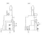
Japanese Laid-Open Patent Publication No. 57-67463 discloses a cathode ray tube socket substrate.
This is a circuit board 115 to which a cathode ray tube socket attached to a cathode ray tube of a television receiver is attached as shown in FIGS. 4, 5 (a) and 5 (b). Are formed, and the first and second variable resistors 118 and 119 are connected to the anode of the cathode ray tube of the television receiver. A voltage is supplied from a flyback transformer 101 that generates a voltage, and the first and second variable resistors 118 and 119 divide the voltage supplied from the flyback transformer 101, and the first variable resistor 118 uses a cathode ray tube. The focus voltage is generated, and the screen voltage is generated by the second variable resistor 119.
However, in this case, after adjusting the knobs 120 and 121 of the first and second variable resistors 118 and 119, there is no mechanism for fixing these knobs 120 and 121, and these knobs 120 are adjusted after adjustment. , 121 may rotate unnecessarily, and the respective adjustment values cannot be maintained.
[0004]
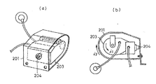
Japanese Laid-Open Patent Publication No. 61-107276 discloses a CRT monitor.
In the CRT monitor, a metallic closed ring 201 is provided, and the ring 201 is not directly fixed to the flyback transformer 203 but covers the flyback transformer 203 during mounting.
However, even in this case, there is no mechanism for locking the adjustment knob 204 after the adjustment knob 204 in the flyac transformer is adjusted, and the adjustment knob 204 may rotate unnecessarily after adjustment. There was a problem that the adjustment value could not be maintained.
[0005]
[Problems to be solved by the invention]
The present invention eliminates the above-mentioned conventional problems, and after adjusting each of the focus adjustment knob and the brightness adjustment knob provided on the flyback transformer main body, these knobs can be locked and simplified. Locking mechanism of the adjustment knob in the flyback transformer that can be made into a simple structure, eliminates the need for fixing with a bond, reduces the man-hours on the production line, and eliminates secondary defects such as misalignment after locking. The purpose is to provide.
[0006]
[Means for Solving the Problems]
The present invention has been proposed to solve the above problems, and the invention according to claim 1 rotates the focus adjustment knob and the brightness adjustment knob in the focus pack provided in the flyback transformer main body. The adjustment knob lock mechanism in the flyback transformer is configured to lock the knobs so that the knobs do not rotate with the adjustment value after adjustment, and is vertically long on the side wall of the housing portion of the focus pack. An opening groove is formed, and in the opening groove, a lock member having a substantially U-shaped body portion is pivotally disposed so as to be rotatable so that the adjustment operation portion is exposed to the outside, and is pivotally attached. An uneven tooth profile for locking is provided in the vicinity of the tip of the upper and lower arms of the main body, and a gear is provided on the shaft inside the casing of each knob, and the locking member is When the rotation operation is performed in any one of the lower directions, the locking concave-convex tooth profile portion of the lock member is engaged with the gear portion of each knob so that the respective knobs are locked so as not to rotate. It is characterized by that.
[0007]
According to the second aspect of the present invention, after the focus adjustment knob and the brightness adjustment knob in the focus pack provided in the flyback transformer main body are rotated and adjusted, the respective knobs are locked so as not to rotate at the adjustment value. A locking mechanism for an adjustment knob in the flyback transformer, wherein a rotation locking portion is provided at a tip portion located inside the casing part of the focus pack in each knob, and a housing for the focus pack is provided. A variable resistor attached to the body is provided with an adjustment locking portion that is locked by a rotation locking portion at the tip when the knob is pushed, and the tip of the knob is rotated when the knob is pushed in. The locking portion for locking is locked to the locking portion of the variable resistor, and each knob is rotated and adjusted. Viewed by the urging outwardly rotating locking part of the knob is disengaged from the adjustment locking portion of the variable resistor is characterized in that so as to the locked state.
According to a third aspect of the present invention, the rotation locking portion is formed in a gear tooth shape, and the variable resistance locking portion is locked by the gear tooth shape rotation locking portion. It is characterized by being formed in a hole-shaped inward gear tooth shape.
[0008]
DETAILED DESCRIPTION OF THE INVENTION
Embodiments of a lock mechanism for an adjusting knob in a flyback transformer according to the present invention will be described below with reference to the drawings.
1A and 1B show a flyback transformer having a lock mechanism for an adjustment knob according to a first embodiment of the present invention. FIG. 1A is a side view thereof, FIG. 1B is a front view thereof, and FIG. The main part is shown, (a) is a perspective view thereof, (b) is an internal structure diagram in a state where each knob can be adjusted in a free state, and (c) is an internal structure diagram when each knob is locked.
[0009]
As shown in FIGS. 1A and 1B, the lock mechanism of the adjustment knob in the flyback transformer of the first embodiment is provided with a focus pack 2 on the front side of the flyback transformer main body 1, and this focus pack. A focus adjustment knob 3 and a light / dark adjustment knob 4 are provided so as to protrude from the front surface of the lens, and these knobs 3 and 4 are adjusted as shown in FIGS. After that, a lock mechanism 5 is provided for locking the knobs 3 and 4 so that the adjustment values are not changed unnecessarily.
The lock mechanism 5 has a long opening groove 2a formed vertically on the side wall of the focus pack 2 so that the main body portion 6a can operate a substantially U-shaped lock member 6 and its adjustment operation portion 6b can be operated outside the side wall. A pivot 9 is pivotally mounted around the pivot 9 so as to be exposed.
[0010]
The upper and lower arms 6c and 6d of the substantially U-shaped body portion 6a of the lock member 6 are provided with locking concave and convex tooth portions 6e and 6f, and the shaft portion 3a inside the housing portion of the knobs 3 and 4 is provided. 4a is provided with gear portions 3b and 4b. When the adjustment operation portion 6b of the lock member 6 is turned downward as shown in FIG. 2C, the lock member 6 is locked. The concave and convex tooth profile portions 6e and 6f are engaged with the gear portions 3b and 4b of the respective knobs 3 and 4 at the same time so that the respective knobs 3 and 4 are locked so that they cannot be rotated.
When the adjustment operation portion 6b of the lock member 6 is turned downward, the adjustment operation portion is locked and fixed by the locking small protrusion 2c provided at a predetermined position of the opening groove 2a. Thus, the non-rotatable state of the knobs 3 and 4 is maintained.
[0011]
Therefore, after the focus adjustment knob 3 and the brightness adjustment knob 4 provided on the flyback transformer main body 1 are respectively adjusted by turning, the adjustment operation portion 6b of the lock member 6 is simply rotated downward. These knobs 3 and 4 can be locked by the lock member 6 and can be made simple, and it is not necessary to fix with a bond, so that the number of steps in the production line can be reduced. Secondary defects such as misalignment can be eliminated.
[0012]
FIGS. 3A and 3B show a lock mechanism for the adjustment knob in the flyback transformer of the second embodiment, wherein FIG. 3A is a partial longitudinal sectional view of the main part in the locked state, and FIG. 3B is the main part at the time of adjustment by the rotation operation. FIG.
The locking mechanism for the adjusting knob in the flyback transformer of the second embodiment is such that a guide protrusion 2b is provided on the back side of the front wall 2d of the focus pack 2 to guide the insertion and removal of the knobs 3 and 4. In each of these knobs 3, 4, gear tooth-shaped rotation locking portions 3 c, 4 c are provided at the tip portions located inside the housing portion of the focus pack 2, and the rear of the housing of the focus pack 2. A hole-shaped inward gear tooth shape into which the locking portions 3c and 4c having a gear tooth shape at the tip are engaged and locked when the knobs 3 and 4 are pushed into the variable resistor 7 attached to the wall 2e with a finger. An adjustment locking portion 7a is provided, and a spring 8 for biasing each knob 3, 4 outward is interposed in a gap between each knob 3, 4 and the variable resistor 7.
[0013]
When the knobs 3 and 4 are pushed in with fingers, the rotation locking portions 3c and 4c at the tips of the knobs 3 and 4 are engaged and locked into the adjustment locking portions 7a of the variable resistor 7. The knobs 3 and 4 are rotated and adjusted. After that, when the fingers are released from the knobs 3 and 4, the knobs 3 and 4 are moved outward by the biasing force of the springs 8. Since 4c is disengaged from the adjustment locking portion 7a of the variable resistor 7, the adjustment locking portion 7a of the variable resistor 7 cannot be rotated from the outside and is locked, and the adjustment value is maintained. It will be.
[0014]
Therefore, after adjusting the variable resistor 7 by turning the focus adjustment knob 3 and the light / dark adjustment knob 4 provided on the flyback transformer main body 1, the adjustment locking portions 7a of the variable resistor 7 are rotated from the outside. It can be locked so that it can not be done, and it can be made a simple structure, it does not need to be fixed with a bond, it can reduce the man-hour on the production line, and eliminate secondary defects such as misalignment after locking Can do.
[0015]
【The invention's effect】
As described above, according to the first aspect of the present invention, after adjusting the focus adjustment knob and the brightness adjustment knob in the focus pack provided in the flyback transformer main body, each knob is adjusted with this adjustment value. A lock mechanism for an adjustment knob in a flyback transformer that is locked so as not to rotate. A long opening groove is formed vertically on the side wall of the housing portion of the focus pack, and a main body portion is formed in the opening groove. An approximately U-shaped lock member is pivotally mounted so that its adjustment operation part is exposed so as to be exposed to the outside, and is pivotally mounted. When the lock member is rotated in either the up or down direction by providing a gear portion on the shaft inside the housing portion of each knob, the lock member is locked. And uneven tooth portion meshed with the gear portion of the knob, since the knob is configured to lock so as to not rotate, the effect described below.
[0016]
That is, after adjusting the focus adjustment knob and the brightness adjustment knob provided on the flyback transformer main body, each knob can be adjusted with a simple operation by rotating the adjustment operation part of the lock member downward. It can be locked with a locking member, and it can be made simple and does not need to be fixed with a bond, reducing the man-hours on the production line and eliminating secondary defects such as misalignment after locking. Can do.
[0017]
According to the second aspect of the present invention, after the focus adjustment knob and the brightness adjustment knob in the focus pack provided in the flyback transformer main body are rotated and adjusted, the respective knobs are locked so as not to rotate with the adjustment value. A lock mechanism for the adjustment knob in the flyback transformer configured as described above, wherein a rotation locking portion is provided at a tip portion located inside the housing portion of the focus pack in each knob, and is attached to the housing of the focus pack. The variable locking resistor is provided with an adjustment locking portion that locks the rotation stopper when the knob is pushed in. When the knob is pushed in, the rotation locking portion at the tip of the knob becomes a variable resistance. Each knob is rotated and adjusted, and the knob is urged outward by a spring to lock the knob for rotation. It was allowed to disengaged from the adjustment locking portion of the variable resistance since so that the locked state, an effect described below.
[0018]
That is, after adjusting the variable resistance by turning the focus adjustment knob and the light / dark adjustment knob provided on the flyback transformer body, lock each adjustment locking portion of the variable resistance so that it cannot be rotated from the outside. In addition, the structure can be made simple, it is not necessary to fix with a bond, the number of steps in the production line can be reduced, and secondary defects such as a shift after locking can be eliminated.
[0019]
According to a third aspect of the present invention, the rotation locking portion is formed in a gear tooth shape, and the variable resistance locking portion is a hole in which the gear tooth-shaped rotation locking portion enters and is rotatably locked. Because it is formed in the shape of an inward gear tooth shape, the rotation locking part can be easily and reliably meshed with the variable resistance adjustment locking part, and the variable resistance can be adjusted accurately by rotating each knob. In addition, the rotation locking portion can be easily detached from the variable resistance adjustment locking portion by the biasing force of the spring, and the adjustment value of the variable resistance can be accurately maintained.
[Brief description of the drawings]
FIGS. 1A and 1B show a flyback transformer provided with a lock mechanism for an adjusting knob according to a first embodiment, wherein FIG. 1A is a side view thereof and FIG. 1B is a front view thereof.
FIGS. 2A and 2B show a main part of the first embodiment, wherein FIG. 2A is a perspective view thereof, FIG. 2B is an internal structure diagram in which each knob can be adjusted in a free state, and FIG. It is an internal structure figure when doing.
FIGS. 3A and 3B show a lock mechanism of an adjustment knob in a flyback transformer according to a second embodiment, wherein FIG. 3A is a partial longitudinal sectional view of a main part in the locked state, and FIG. It is a partial longitudinal cross-sectional view of a part.
FIG. 4 is a perspective view of a flyback transformer and an adjustment unit showing a conventional cathode ray tube socket substrate and showing an example in which an adjustment unit is provided separately from the flyback transformer.
5A is a perspective view showing an embodiment of a cathode ray tube socket substrate provided with a focus voltage adjustment unit and a screen voltage adjustment unit, and FIG. 5B is a partial perspective view thereof.
FIG. 6 is an overall configuration diagram of a conventional CRT monitor.
7A and 7B show the CRT monitor, in which FIG. 7A is a partial detail view thereof, and FIG. 7B is a partial side view thereof.
[Explanation of symbols]
DESCRIPTION OF SYMBOLS 1 Flyback transformer main body 2 Focus pack 2a Opening groove 3 Adjustment knob 3a Shaft part 3b Gear part 3c Rotation locking part 4 Light / dark adjustment knob 4a Shaft part 4b Gear part 4c Rotation locking part 5 Lock mechanism 6 Lock member 6a Main body portion 6b Adjustment operation portions 6c, 6d Upper and lower arm portions 6e, 6f Uneven tooth shape portion for locking 7 Variable resistor 7a Locking portion 8 for adjustment Spring