JP3660004B2 - Drilling machine - Google Patents
Drilling machine Download PDFInfo
- Publication number
- JP3660004B2 JP3660004B2 JP01435595A JP1435595A JP3660004B2 JP 3660004 B2 JP3660004 B2 JP 3660004B2 JP 01435595 A JP01435595 A JP 01435595A JP 1435595 A JP1435595 A JP 1435595A JP 3660004 B2 JP3660004 B2 JP 3660004B2
- Authority
- JP
- Japan
- Prior art keywords
- press
- punch
- strip
- piston
- cylinder
- Prior art date
- Legal status (The legal status is an assumption and is not a legal conclusion. Google has not performed a legal analysis and makes no representation as to the accuracy of the status listed.)
- Expired - Lifetime
Links
- 238000005553 drilling Methods 0.000 title claims description 22
- 238000004080 punching Methods 0.000 claims description 10
- 229910000831 Steel Inorganic materials 0.000 description 6
- 239000010959 steel Substances 0.000 description 6
- 230000000694 effects Effects 0.000 description 2
- 238000007796 conventional method Methods 0.000 description 1
- 238000005516 engineering process Methods 0.000 description 1
- 239000002699 waste material Substances 0.000 description 1
Images


Landscapes
- Punching Or Piercing (AREA)
Description
【0001】
【産業上の利用分野】
この発明は穴明け加工機に係り、さらに詳しくは、パンチで形鋼に穴明け加工するのに適する穴明け加工機に関するものである。
【0002】
【従来の技術】
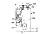
従来より、Cチャンネルやチャンネル等の形鋼のフランジにパンチで穴明けする穴明け加工機のパンチングユニット101としては、図4〜図6に示されるようなもの一般的である。
【0003】
このようなパンチングユニット101では、上下方向に溝を有する断面U字形状のホルダガイド103の溝部分にパンチホルダ105が上下動自在に設けられており、ホルダガイド103の前面(図5中左側面)にはパンチホルダ105が前方へ脱落しないようにパンチガイド部材107がボルト109により取付けられている。またホルダガイド103下端部の溝部分にはベースプレート111がボルト113により取付けられている。
【0004】
このパンチホルダ105は断面ト字形状をしており、中央部分が突出しその先端部分に下向きにパンチ115がボルト117で着脱自在に装着されている。また、パンチホルダ105の上端部には、プレート119がボルト121により取付けられており、このプレート119はホルダガイド103よりも若干上方へ突出している。このプレート119の上面に図示しないプレスから下向きのプレス力を受ける。
【0005】
パンチホルダ105の下側には前記ベースプレート111との間にパンチリフトバネ123が設けられており、プレスが上昇したときにパンチホルダ105を上昇させるようになっている。また、パンチホルダ105の上端後側にはストッパ125がボルト127によりホルダガイド103に取付けられており、パンチリフトバネ123がパンチホルダ105を上昇させた際に行き過ぎないようにしている。
【0006】
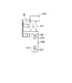
前記ベースプレート111上にはダイホルダ129が取付けられており、このダイホルダ129に前記パンチ115に対向するダイ131が取付けられている。ダイホルダ129内部およびベースプレート111内部には、パンチ115とダイ131との協働によりワークWを打ち抜いたスクラップが落下するための空洞133が設けられている。
【0007】
ホルダガイド103左右両側面(図4中左右両側面)の中央部から下端部にかけて、断面逆L字形状をしたワーク押えとしてのストリッパ135が長円孔137を介してボルト139により若干の上下動が可能に取付けられている(図6参照)。このストリッパ135の上側には、前記パンチホルダ105のプレート119との間にストリップバネ141が設けられている。このストリップバネ141は、先端部のみネジ部を有すると共にプレート119に対して上方向へ突出自在のボルト143によりストリッパ135に取付けられている。
【0008】
従って、プレスによりプレート119に下向き力が作用した場合には、ストリップバネ141によりストリッパ135は長円孔137の範囲で押し下げられる。さらにプレート119に下向き力が作用すると、ストリッパ135は下降せずにパンチホルダ105のみが下降することになる。また、プレス力が解放されると、パンチホルダ105がパンチリフトバネ123により上昇するが、ストリッパ135はストリップバネ141により下方へ押し下げられているので最初は上昇しない。さらにパンチホルダ105が上昇すると、ボルト143の働きによりストリッパ135も引き上げられる。
【0009】
以上のように構成されているので、チャンネル等の形鋼であるワークWをパンチ115とダイ131の間にセットし、図示しないプレスがプレート119を打撃してパンチホルダ105を下降させる。この時、まずストリッパ135が下降してワークWを押え、さらにパンチホルダ105のみが下降してパンチ115とダイ131との協働によりワークWに穴明け加工を行う。穴明け加工が完了してプレスが上昇すると、ストリッパ135は上昇せずにパンチホルダ105が上昇してパンチ115がワークWからはずれる。その後、ストリッパ135もパンチホルダ105と共に上昇して加工を完了する。
【0010】
【発明が解決しようとする課題】
しかしながら、このような従来の技術にあっては、プレス部とパンチングユニット101が分離しており、パンチリフトバネ123およびストリップバネ141はパンチングユニット101に設けられている。このため、パンチングユニット101の幅が大きくなり、ストリッパ135がパンチ115位置から大きくずれるのでワークW端部の穴明け位置が制限される。また、ストリッパ135を下向きに押し下げるのにストリップバネ141を使用しているので大きな力がとれずストリップミスが発生するおそれがある。
【0011】
この発明の目的は、以上のような従来の技術に着目してなされたものであり、形鋼の穴明け加工においてストリップミスを防止することができる穴明け加工機を提供することにある。
【0012】
【課題を解決するための手段】
本発明は前述のごとき問題に鑑みてなされたもので、ワーク押えで押さえられたワークに対してパンチとダイとの協働により穴明けする穴明け加工機であって、前記パンチに穴明けのためのプレス力を付与するプレス用シリンダに上下動自在に備えたプレス用ピストンの内部に、前記ワーク押えを上下動するためのストリップ用ピストンを上下動自在に備えたワーク押え用シリンダを設けてなり、前記プレス用ピストンを下降するときに圧油を注入するプレス用上シリンダ室と、前記プレス用ピストンを上昇するときに圧油を注入するプレス用下シリンダ室とを前記プレス用シリンダに備え、前記ストリップ用ピストンを下降するために前記ワーク押えシリンダに備えたストリップ用シリンダ室と前記プレス用下シリンダ室とを油路を介して常に連通してあることを特徴とするものである。
【0020】
【実施例】
以下、この発明の好適な一実施例を図面に基づいて説明する。
【0021】
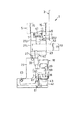
図1〜図3には穴明け加工機1の主要部が示されている。図2において、フレーム3の上端部には穴明け力を発生するプレス用シリンダ5が設けられており、そのプレス用ピストン7内部にはさらにワーク押え用シリンダであるストリップ用シリンダ9が設けられている。すなわち、プレス用ピストン7自体をストリップ用シリンダ9とし、このストリップ用シリンダ9の内部にストリップ用ピストン11が上下動自在に設けられている。
【0022】
プレス用シリンダ5には、プレス用ピストン7の下降時に圧油を注入するプレス用上シリンダ室13Uと、プレス用ピストン7の上昇時に圧油を注入するプレス用下シリンダ室13Lが設けられており、ピストンリング15,15により密閉されている。前記プレス用下シリンダ室13Lは油路17によりストリップ用シリンダ室19と連通している。
【0023】
また、プレス用ピストン7の下側には上下のストライカ21U,21Lが設けられている。下ストライカ21Lの下側には前後方向(図2中左右方向)に溝23が設けられており、この溝23にパンチホルダ25の頭部27が前後方向に挿入されていてパンチホルダ25と下ストライカ21Lは上下方向に一体に移動するようになっている。
【0024】
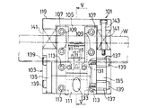
図3を併せて参照するに、パンチホルダ25は中央部分が前方(図1中紙面直交方向手前側,図3中右方向)へ突出するパンチ取付部29を有しており、このパンチ取付部29にパンチ31がボルト33により装着されている。また、上下方向に溝を有する断面U字形状のホルダガイド35がパンチホルダ25を左右両側(図1中左右両側)からガイドすべく設けられている。
【0025】
また、ホルダガイド35に設けられているガイドピン37がパンチホルダ25の後端(図3中左側端)上部付近に設けられている切欠き39内を相対的に上下動することにより、パンチホルダ25の前後方向(図3中左右方向)のブレが抑止されている。すなわち、パンチホルダ25はホルダガイド35の溝に沿って上下動するものである。
【0026】
そして、ホルダガイド35の下端部前側にはダイホルダ41が設けられており、このダイホルダ41には前記パンチ31に対向するダイ43が設けられている。
【0027】
一方、ストリップ用ピストン11にはボス45を介してピン47によりコネクタ49が取付けられており、このコネクタ49の前後(図2中左右)には前述の上ストライカ21Uが設けられている。コネクタ49の下部は二股に分かれて下ストライカ21Lを跨いだ状態となっており、コネクタ49の下側で下ストライカ21Lの左右両側(図1中左右両側)にはヒンジ51を中心に上下方向に回動するヒンジアーム53が設けられている。
【0028】
左右のヒンジアーム53,53の下側には、前述のホルダガイド35に設けられている摺動ガイド部55,55により上下方向にガイドされるストリップバー57,57が各々設けられており、各ストリップバー57の下側にはワーク押えとしてのストリップアーム59,59が各々設けられている。また、このストリップアーム59,59の下側にはスプリング61が設けられている。
【0029】
このストリップアーム59はホルダガイド35に取付けられたヒンジピン63を中心として上下方向に回動自在となっているが、常時はスプリング61により上向きの回転力が付勢されている。また、ストリップアーム59は、ストリップアーム59に設けられている円弧状の切欠き65とホルダガイド35に取付けられているガイドピン67の作用により一定の範囲でのみ回動する。
【0030】
次に、穴明け加工における動作を説明する。まず、パンチ31およびストリップアーム59が上側にある状態で形鋼のワークWを所定位置にセットしておく。その後、プレス用シリンダ5のプレス用上シリンダ室13Uに圧油を注入してプレス用ピストン7を下降させる。この時、プレス用シリンダ5のプレス用下シリンダ室13Lの圧油がプレス用ピストン7の油路17からストリップ用シリンダ室19に送られるのでストリップ用ピストン11がプレス用ピストン27より早く下降する。
【0031】
ストリップ用ピストン11の下降力はボス45およびコネクタ49を介してヒンジアーム53を下向きに回動させ、ヒンジアーム53がストリップバー57を押し下げる。ストリップバー57はストリップアーム59を下向きに回動させて先端部でワークWを押さえる。但し、ストリップアーム59は一定量しか下向きに回動せず、ストリップ用ピストン11の下降も停止する。
【0032】
さらに圧油をプレス用上シリンダ室13Uに注入するとプレス用ピストン7は下降を続けるが、ストリップ用ピストン11の下降は停止していて相対的にプレス用ピストン7に対して上昇するるのでストリップ用シリンダ室19の廃油は排出される。このプレス用ピストン7の下降力は上下のストライカ21U,21Lを介してパンチホルダ25に伝達され、パンチ31を下降させてダイ43との協働によりワークWに穴明け加工を行う。
【0033】
一方、穴明け加工が完了するとプレス用シリンダ5のプレス用下シリンダ室13Lに圧油を注入してプレス用ピストン7を上昇させようとするが、この圧油はプレス用ピストン7に設けられている油路17を通じて再びストリップ用シリンダ室19に注入されるので、ストリップ用ピストン11を下降させようとする。従って、プレス用ピストン7の上昇にもかかわらずストリップ用ピストン11は上昇せずにストリップアーム59を下向きに押さえ続ける。
【0034】
また、パンチホルダ25の頭部が下ストライカ21Lに嵌合しているので、プレス用ピストン7がストライカ21U,21Lを引き上げるとパンチホルダ25も上昇し、パンチ31がワークWから離脱する。
【0035】
そして、プレス用ピストン7がストリップ用ピストン11に対して所定量だけ相対的に上昇すると、以後ストリップ用ピストン11はプレス用ピストン7の上昇に伴って上昇する。このため、ストリップアーム59はストリップ用シリンダ9からの下向力から解放され、スプリング61の反発力により上向きに回動してワークWから離れる。
【0036】
このような穴明け加工機1によれば、従来スプリングバネにより得ていたパンチリフト力およびストリップ力をプレス用シリンダ5から得ることとしたのでパンチリフトバネ123およびストリップバネ141等(図4,図5,図6参照)が不要となり、穴明け加工機1の幅を狭くすることが可能になる。このため、ワーク押えであるストリップアーム59がパンチ31付近で作動することとなり、ワークWの端部付近に穴明け加工が可能になる。
【0037】
また、パンチ31を装着したパンチホルダ25とストライカ21を上下方向に接続したのでパンチ31を引き上げる力がプレス用シリンダ5により得られるとともに、ストリップアーム59を押さえる力もプレス用シリンダ5により得られるため、ストリップミスを防止することができる。
【0038】
なお、この発明は、前述した実施例に限定されることなく、適宜な変更を行なうことにより、その他の態様で実施し得るものである。例えば、上記実施例においては、プレス用シリンダ5およびストリップ用シリンダ9に油圧シリンダを用いたが、エアーシリンダを用いても同様の作用効果を得ることができる。
【0039】
【発明の効果】
本発明によれば、ワーク押えが所定位置に位置決めされたワークである形鋼を押え、パンチとダイとの協働により穴明け加工を行う際に、プレス用シリンダのピストン内部に設けられているワーク押え用シリンダが前記ワーク押えを下降させてワークを押さえ、プレス用シリンダがパンチを下方へ打撃して穴明けを行う。そして、穴明け後は、プレス用シリンダがパンチを上昇させ、その後ワーク押えが上昇してワークを解放するので、従来のようにスプリングでパンチを上昇させると共にスプリングでワークを押さえる場合と異なり、十分な上昇力およびワーク押え力を得ることができ、ストリップミスを起こすのを防止することができる。また、プレス用シリンダのピストン内部にワーク押え用シリンダが設けられているので従来のようにパンチリフト用のスプリングを設けるスペースが不要であり、加工機の幅を小さくすることが可能になる。
【図面の簡単な説明】
【図1】この発明に係る穴明け加工機の一実施例の主要部を示す正面図である。
【図2】図1中II方向から見た側面図である。
【図3】図1中III −III 位置から見た断面図である。
【図4】従来の穴明け加工機におけるパンチングユニットを示す正面図である。
【図5】図4中V−V位置における断面図である。
【図6】図5におけるワーク押え(ストリッパ)の詳細図である。
【符号の説明】
1 穴明け加工機
5 プレス用シリンダ
7 プレス用ピストン
9 ストリップ用シリンダ(ワーク押え用シリンダ)
25 パンチホルダ
31 パンチ
43 ダイ
59 ストリップアーム(ワーク押え)
W ワーク[0001]
[Industrial application fields]
The present invention relates to a drilling machine, and more particularly to a drilling machine suitable for punching a shape steel with a punch.
[0002]
[Prior art]
Conventionally, as a
[0003]
In such a
[0004]
The
[0005]
A
[0006]
A die
[0007]
A
[0008]
Therefore, when a downward force is applied to the
[0009]
Since it is configured as described above, the workpiece W, which is a shape steel such as a channel, is set between the
[0010]
[Problems to be solved by the invention]
However, in such a conventional technique, the press unit and the
[0011]
An object of the present invention is made by paying attention to the conventional technology as described above, and is to provide a drilling machine capable of preventing a strip error in drilling a shape steel.
[0012]
[Means for Solving the Problems]
The present invention has been made in view of the above-described problems, and is a drilling machine for drilling a workpiece pressed by a workpiece presser by cooperation of a punch and a die, and the punch is punched. inside the press piston with vertically movable press cylinder for imparting the press force for the strip piston for vertically moving the work holding provided vertically movable with the work holding cylinder Do Ri, and on a press cylinder chamber for injecting pressurized oil when descending the press piston, and under a press cylinder chamber for injecting pressurized oil when increasing the press piston to the press cylinder A strip cylinder chamber and a press lower cylinder chamber provided in the work pressing cylinder for lowering the strip piston via an oil passage. It is characterized in that are communicating with.
[0020]
【Example】
Hereinafter, a preferred embodiment of the present invention will be described with reference to the drawings.
[0021]
The main part of the boring machine 1 is shown in FIGS. In FIG. 2, a
[0022]
The
[0023]
In addition, upper and
[0024]
Referring also to FIG. 3, the
[0025]
Further, the
[0026]
A
[0027]
On the other hand, a
[0028]
Below the left and right hinge
[0029]
The
[0030]
Next, the operation in drilling will be described. First, a workpiece W made of a shaped steel is set at a predetermined position with the
[0031]
The descending force of the
[0032]
Further, when the pressure oil is injected into the
[0033]
On the other hand, when the drilling is completed, pressure oil is injected into the press
[0034]
Further, since the head of the
[0035]
Then, when the
[0036]
According to such a drilling machine 1, since the punch lift force and strip force obtained by the conventional spring spring are obtained from the
[0037]
Further, since the
[0038]
In addition, this invention is not limited to the Example mentioned above, It can implement in another aspect by making an appropriate change. For example, in the above embodiment, hydraulic cylinders are used for the
[0039]
【The invention's effect】
According to the present invention, the work presser is provided inside the piston of the press cylinder when pressing the shaped steel as a work positioned at a predetermined position and performing drilling by the cooperation of the punch and the die. The workpiece pressing cylinder lowers the workpiece pressing to hold the workpiece, and the pressing cylinder strikes the punch downward to make a hole. And after drilling, the press cylinder raises the punch, and then the workpiece presser rises to release the workpiece, so unlike the conventional case where the punch is raised by the spring and the workpiece is held by the spring, it is sufficient High lifting force and workpiece pressing force can be obtained, and stripping errors can be prevented. Further, since the workpiece pressing cylinder is provided inside the piston of the pressing cylinder, there is no need for a space for providing a punch lift spring as in the prior art, and the width of the processing machine can be reduced.
[Brief description of the drawings]
FIG. 1 is a front view showing a main part of an embodiment of a drilling machine according to the present invention.
FIG. 2 is a side view seen from the direction II in FIG.
3 is a cross-sectional view taken from the position of III-III in FIG.
FIG. 4 is a front view showing a punching unit in a conventional drilling machine.
FIG. 5 is a cross-sectional view taken along the line VV in FIG.
6 is a detailed view of the work presser (stripper) in FIG. 5. FIG.
[Explanation of symbols]
1
25
W Work
Claims (1)
Priority Applications (1)
| Application Number | Priority Date | Filing Date | Title |
|---|---|---|---|
| JP01435595A JP3660004B2 (en) | 1995-01-31 | 1995-01-31 | Drilling machine |
Applications Claiming Priority (1)
| Application Number | Priority Date | Filing Date | Title |
|---|---|---|---|
| JP01435595A JP3660004B2 (en) | 1995-01-31 | 1995-01-31 | Drilling machine |
Publications (2)
| Publication Number | Publication Date |
|---|---|
| JPH08206747A JPH08206747A (en) | 1996-08-13 |
| JP3660004B2 true JP3660004B2 (en) | 2005-06-15 |
Family
ID=11858769
Family Applications (1)
| Application Number | Title | Priority Date | Filing Date |
|---|---|---|---|
| JP01435595A Expired - Lifetime JP3660004B2 (en) | 1995-01-31 | 1995-01-31 | Drilling machine |
Country Status (1)
| Country | Link |
|---|---|
| JP (1) | JP3660004B2 (en) |
Families Citing this family (1)
| Publication number | Priority date | Publication date | Assignee | Title |
|---|---|---|---|---|
| JP6639327B2 (en) * | 2016-05-24 | 2020-02-05 | 未来工業株式会社 | Drilling tool and through hole processing device |
-
1995
- 1995-01-31 JP JP01435595A patent/JP3660004B2/en not_active Expired - Lifetime
Also Published As
| Publication number | Publication date |
|---|---|
| JPH08206747A (en) | 1996-08-13 |
Similar Documents
| Publication | Publication Date | Title |
|---|---|---|
| JP3540308B2 (en) | Slide cam type | |
| JP5358927B2 (en) | Total shearing die | |
| US6220137B1 (en) | Press apparatus | |
| GB2059322A (en) | Machine tool | |
| JPH1119728A (en) | Press device using double-acting press machine | |
| KR20000034882A (en) | Press apparatus | |
| JP5556919B2 (en) | Total shearing die | |
| JP3660004B2 (en) | Drilling machine | |
| JP3617385B2 (en) | Press mold | |
| JP4185786B2 (en) | Knockout device for press machine | |
| JP5219417B2 (en) | Bending system | |
| KR20020058789A (en) | Piercing press system | |
| JPH04162925A (en) | Device for working hole | |
| KR20030005637A (en) | Piercing press | |
| JP2591391B2 (en) | Punching die | |
| JPS61182842A (en) | Metal pipe plastic processing equipment | |
| JP3946564B2 (en) | Method of start-up / punch-down by punch press and punch mold and die mold used for the method | |
| WO2001083135B1 (en) | Method and impact machine for forming a body | |
| JPS6130748Y2 (en) | ||
| JPH06238360A (en) | Equipment for embossing and drilling | |
| JPS628897Y2 (en) | ||
| JP4521073B2 (en) | Overtake mold | |
| JPS6110880Y2 (en) | ||
| JP2002178038A (en) | Bending die | |
| JP3211974B2 (en) | Burring mold |
Legal Events
| Date | Code | Title | Description |
|---|---|---|---|
| A977 | Report on retrieval |
Free format text: JAPANESE INTERMEDIATE CODE: A971007 Effective date: 20040716 |
|
| A131 | Notification of reasons for refusal |
Free format text: JAPANESE INTERMEDIATE CODE: A131 Effective date: 20040727 |
|
| A521 | Written amendment |
Free format text: JAPANESE INTERMEDIATE CODE: A523 Effective date: 20040924 |
|
| TRDD | Decision of grant or rejection written | ||
| A01 | Written decision to grant a patent or to grant a registration (utility model) |
Free format text: JAPANESE INTERMEDIATE CODE: A01 Effective date: 20050308 |
|
| A61 | First payment of annual fees (during grant procedure) |
Free format text: JAPANESE INTERMEDIATE CODE: A61 Effective date: 20050316 |
|
| R150 | Certificate of patent or registration of utility model |
Free format text: JAPANESE INTERMEDIATE CODE: R150 |
|
| FPAY | Renewal fee payment (event date is renewal date of database) |
Free format text: PAYMENT UNTIL: 20080325 Year of fee payment: 3 |
|
| FPAY | Renewal fee payment (event date is renewal date of database) |
Free format text: PAYMENT UNTIL: 20090325 Year of fee payment: 4 |
|
| FPAY | Renewal fee payment (event date is renewal date of database) |
Free format text: PAYMENT UNTIL: 20100325 Year of fee payment: 5 |
|
| FPAY | Renewal fee payment (event date is renewal date of database) |
Free format text: PAYMENT UNTIL: 20100325 Year of fee payment: 5 |
|
| FPAY | Renewal fee payment (event date is renewal date of database) |
Free format text: PAYMENT UNTIL: 20110325 Year of fee payment: 6 |
|
| FPAY | Renewal fee payment (event date is renewal date of database) |
Free format text: PAYMENT UNTIL: 20120325 Year of fee payment: 7 |
|
| FPAY | Renewal fee payment (event date is renewal date of database) |
Free format text: PAYMENT UNTIL: 20130325 Year of fee payment: 8 |